JP2010063269A - Electrical junction box - Google Patents
Electrical junction box Download PDFInfo
- Publication number
- JP2010063269A JP2010063269A JP2008226383A JP2008226383A JP2010063269A JP 2010063269 A JP2010063269 A JP 2010063269A JP 2008226383 A JP2008226383 A JP 2008226383A JP 2008226383 A JP2008226383 A JP 2008226383A JP 2010063269 A JP2010063269 A JP 2010063269A
- Authority
- JP
- Japan
- Prior art keywords
- fuse
- bus bar
- vertical bus
- case
- terminal
- Prior art date
- Legal status (The legal status is an assumption and is not a legal conclusion. Google has not performed a legal analysis and makes no representation as to the accuracy of the status listed.)
- Granted
Links
Images


Classifications
-
- B—PERFORMING OPERATIONS; TRANSPORTING
- B60—VEHICLES IN GENERAL
- B60R—VEHICLES, VEHICLE FITTINGS, OR VEHICLE PARTS, NOT OTHERWISE PROVIDED FOR
- B60R16/00—Electric or fluid circuits specially adapted for vehicles and not otherwise provided for; Arrangement of elements of electric or fluid circuits specially adapted for vehicles and not otherwise provided for
- B60R16/02—Electric or fluid circuits specially adapted for vehicles and not otherwise provided for; Arrangement of elements of electric or fluid circuits specially adapted for vehicles and not otherwise provided for electric constitutive elements
- B60R16/023—Electric or fluid circuits specially adapted for vehicles and not otherwise provided for; Arrangement of elements of electric or fluid circuits specially adapted for vehicles and not otherwise provided for electric constitutive elements for transmission of signals between vehicle parts or subsystems
- B60R16/0238—Electrical distribution centers
Landscapes
- Engineering & Computer Science (AREA)
- Mechanical Engineering (AREA)
- Connection Or Junction Boxes (AREA)
- Multi-Conductor Connections (AREA)
- Connections Arranged To Contact A Plurality Of Conductors (AREA)
Abstract
Description
本発明は、電気接続箱に関し、詳しくは、ケース内部に収容される縦バスバーの水平折曲部にヒューズ接続端子を設けた電気接続箱において、ヒューズの挿入力による縦バスバーの変形の防止を図るものである。 The present invention relates to an electrical connection box, and more particularly, in an electrical connection box in which a fuse connection terminal is provided at a horizontal bent portion of a vertical bus bar housed in a case, the vertical bus bar is prevented from being deformed by the insertion force of the fuse. Is.
電気接続箱において、ケースの表面に設けたヒューズ収容部に差し込むヒューズは、ケース内部に内部回路材として収容しているバスバーのヒューズ接続端子と接続される。該バスバーはケース内部に絶縁板で支持して水平方向に配置し、該水平配置される平バスバーから立設するヒューズ接続端子にヒューズ端子を接続している場合が多い。この場合、バスバーは絶縁板で支持されているため、ヒューズ装着時の差し込み負荷によりバスバーに変形が発生するのが防止できる。
一方、前記絶縁板で支持する水平方向の平バスバーに変えて、ケースのヒューズ収容部やリレー収容部を設けたケースの上下面に対して、バスバーを垂直方向に配置する縦バスバーが用いられる場合がある。この縦バスバーを使用すると平バスバーよりも絶縁板の使用量の低減が図れ、電気接続箱の軽量化および小型化が可能となる利点がある。しかしながら、縦バスバーはケースのフレームと係止して保持し、絶縁板で支持していないため、ヒューズ接続端子をヒューズと接続する際に上下方向の負荷を受けると変形が発生しやすい問題がある。
In the electrical junction box, the fuse inserted into the fuse accommodating portion provided on the surface of the case is connected to the fuse connection terminal of the bus bar accommodated as an internal circuit material inside the case. In many cases, the bus bar is supported by an insulating plate inside the case and arranged in a horizontal direction, and a fuse terminal is connected to a fuse connection terminal standing upright from the horizontally arranged flat bus bar. In this case, since the bus bar is supported by the insulating plate, the bus bar can be prevented from being deformed by the insertion load when the fuse is mounted.
On the other hand, instead of the horizontal flat bus bar supported by the insulating plate, a vertical bus bar is used in which the bus bar is arranged vertically with respect to the upper and lower surfaces of the case provided with the fuse accommodating portion and the relay accommodating portion. There is. When this vertical bus bar is used, the amount of the insulating plate used can be reduced as compared with the flat bus bar, and there is an advantage that the electric connection box can be reduced in weight and size. However, since the vertical bus bar is locked and held with the frame of the case and is not supported by the insulating plate, there is a problem that deformation is likely to occur when a load is applied in the vertical direction when the fuse connection terminal is connected to the fuse. .
例えば、図5に示す電気接続箱1は、ケース2内に、垂直方向の基板部3aの上端より複数のタブ3bを突設した縦バスバー3を収容固定し、中継端子4を接続した前記タブ3bをケース2のヒューズ収容部5の下部に挿入すると共に、前記中継端子4に上方からヒューズ6の端子6aを挿入して、中継端子4を介して前記縦バスバー3とヒューズ6とを接続している。(実開平7−8966号公報(特許文献1)参照)
前記縦バスバー3は、基板部3aに設けた係止穴3cに、ケース2より突設した係止突起7を挿入係止してケース2に固定している。
For example, the electrical junction box 1 shown in FIG. 5 has the vertical bus bar 3 in which a plurality of
The vertical bus bar 3 is fixed to the case 2 by inserting and locking a locking projection 7 protruding from the case 2 into a locking hole 3 c provided in the substrate portion 3 a.
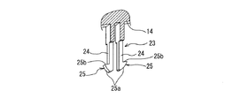
電気接続箱の設計上、図6に示すように、縦バスバー8の垂直方向の基板部8aとヒューズの収容位置との位置ずれが生じると、基板部8を屈曲して水平部8bを形成し、該水平部8bをさらに垂直に折り曲げてタブ8cを形成し、ヒューズ9の端子9aの挿入位置とタブ8cの位置とが合うように調整する場合がある。
Due to the design of the electrical junction box, as shown in FIG. 6, if a positional deviation occurs between the
しかしながら、縦バスバー8を用いる場合、前記水平部8bの下面側を絶縁板等で支持することは少ないため、ヒューズ9の挿入圧によって水平部8bが図中破線で示すように沈み込み、変形しやすい点に問題がある。特に、ヒューズが大容量ヒューズである場合、挿入圧も大きいため、特に水平部8bは変形しやすくなる。
However, when the vertical bus bar 8 is used, since the lower surface side of the
本発明は前記問題に鑑みてなされたもので、電気接続箱のケース内部に収容されてヒューズと接続される縦バスバーに設けられた水平部が、ヒューズの挿入圧を受けて変形することを防止できる電気接続箱の提供を課題としている。 The present invention has been made in view of the above problems, and prevents the horizontal portion provided in the vertical bus bar, which is accommodated inside the case of the electrical junction box and connected to the fuse, from being deformed due to the insertion pressure of the fuse. The challenge is to provide an electrical junction box that can be used.
前記課題を解決するために、本発明は、ケース内部に縦バスバーを収容していると共に、該ケースに設けたヒューズ収容部に差し込まれるヒューズと前記縦バスバーに設けたヒューズ接続用端子とを電気接続している電気接続箱において、
前記縦バスバーに折り曲げて形成した水平部に前記ヒューズ接続用端子を設け、
前記ヒューズ収容部の下方に前記縦バスバーの前記水平部を支持するロック部を設けていることを特徴とする電気接続箱を提供している。
In order to solve the above problems, the present invention accommodates a vertical bus bar inside a case, and electrically connects a fuse inserted into a fuse accommodating portion provided in the case and a fuse connection terminal provided in the vertical bus bar. In the connected electrical junction box,
Provide the fuse connection terminal in a horizontal portion formed by bending the vertical bus bar,
An electrical junction box is provided, wherein a lock portion for supporting the horizontal portion of the vertical bus bar is provided below the fuse housing portion.
このように、縦バスバーの水平部を、ケースのヒューズ収容部の下方に設けたロック部でロック係止することにより、前記水平部はロック部によって支持されるため、ヒューズの挿入圧を受けた際の水平部の沈み込みや変形を防止することができる。 In this way, the horizontal portion of the vertical bus bar is locked and locked by the lock portion provided below the fuse housing portion of the case, so that the horizontal portion is supported by the lock portion, so that the insertion pressure of the fuse is received. The horizontal portion can be prevented from sinking or deforming.
前記ロック部は、ヒューズ収容部の底壁から突設され、係止突部を有する一対の突起部からなり、前記縦バスバーの前記水平部には、前記ロック部が挿入係止される係止穴を設けている。 The lock portion is formed of a pair of protrusions protruding from the bottom wall of the fuse housing portion and having locking protrusions, and the horizontal portion of the vertical bus bar is locked so that the lock portion is inserted and locked A hole is provided.
あるいは、前記ロック部は、ヒューズ収容部を囲む周壁、あるいはヒューズ収容部内の空間を仕切る仕切壁に設けてもよい。 Alternatively, the lock portion may be provided on a peripheral wall surrounding the fuse accommodating portion or a partition wall that partitions a space in the fuse accommodating portion.
前記ヒューズは100A〜50Aの大容量ヒューズで大型の場合、挿入力が大きいため、特に好適となる。 Since the fuse is a large capacity fuse of 100A to 50A and has a large insertion force, it is particularly suitable.
前記縦バスバーに設けるヒューズ接続用端子は、前記水平部から更に垂直方向に屈曲させて形成していることが好ましい。
また、該縦バスバーに設けるヒューズ接続用端子は、ヒューズの入力端子と接続する場合が多い。
ヒューズの出力端子は、前記縦バスバーとは異なるバスバーに接続され、あるいは、電線端末の端子と接続される。ヒューズの出力端子をバスバーと接続する場合において、該バスバーに設けられた水平部が絶縁板等で支持されていない場合は、ヒューズの入力端子と接続される前記縦バスバーの場合と同様に、ヒューズ収容部の壁部に設けたロック部によって水平部をロック係止する構成とすることが好ましい。
It is preferable that the fuse connection terminal provided on the vertical bus bar is formed by further bending in the vertical direction from the horizontal portion.
Further, the fuse connection terminal provided on the vertical bus bar is often connected to the input terminal of the fuse.
The output terminal of the fuse is connected to a bus bar different from the vertical bus bar, or is connected to a terminal of the electric wire terminal. When connecting the output terminal of the fuse to the bus bar, if the horizontal portion provided on the bus bar is not supported by an insulating plate or the like, as in the case of the vertical bus bar connected to the input terminal of the fuse, It is preferable that the horizontal portion is locked and locked by a lock portion provided on the wall portion of the housing portion.
前記ヒューズ収容部は、ケースに複数個並設している場合には、前記縦バスバーに設けるヒューズ接続用端子は、1本の縦バスバーに、前記ヒューズ接続用端子となる複数のタブを間隔をあけて折り曲げて立設している。 When a plurality of the fuse accommodating portions are arranged in parallel in the case, the fuse connecting terminals provided on the vertical bus bar are spaced apart from a plurality of tabs serving as the fuse connecting terminals on one vertical bus bar. Opened, bent and erected.
各ヒューズ収容部内には中継端子を収容し、該中継端子を介して縦バスバーのヒューズ接続用端子とヒューズの端子とを接続する構成としてもよい。該中継端子には雌型端子を好適に用いることができる。 A relay terminal may be accommodated in each fuse accommodating portion, and the fuse connection terminal of the vertical bus bar and the fuse terminal may be connected via the relay terminal. A female terminal can be suitably used as the relay terminal.
前記電気接続箱の例としては、自動車に配索されるワイヤハーネスと接続されるものが挙げられる。 Examples of the electrical junction box include those connected to a wire harness routed in an automobile.
上述したように、本発明によれば、電気接続箱のケースに設けたヒューズ収容部の下方にロック部を形成し、該ロック部によって縦バスバーの水平部をロック係止して支持することができるため、該水平部がヒューズの差し込み時に挿入圧を受けても沈み込みや変形を防止することができる。 As described above, according to the present invention, the lock portion is formed below the fuse housing portion provided in the case of the electrical junction box, and the horizontal portion of the vertical busbar can be locked and supported by the lock portion. Therefore, the horizontal portion can be prevented from sinking or deforming even if it receives an insertion pressure when the fuse is inserted.
以下、本発明の実施形態を図面を参照して説明する。
図1乃至図4に、本発明の第一実施形態に係る電気接続箱10を示す。
電気接続箱10は、自動車に配索されるワイヤハーネスに接続される。該電気接続箱10のケース11は、図1および図2に示すように、上面側にヒューズ収容部12を並設しており、図示の実施形態では2個のヒューズ収容部12を設けている。該ヒューズ収容部12には80Aの大容量のヒューズ40をそれぞれ取り付けている。
Hereinafter, embodiments of the present invention will be described with reference to the drawings.
1 to 4 show an
The
ケース11の内部には内部回路材として縦バスバー30をケース内に設けたランス(図示せず)と係止して固定しており、前記ヒューズ40と接続する内部回路材も縦バスバー30としている。
ケース11の上面と下面にはアッパーカバーとロアカバー(図示せず)を被せ、互いにロック結合させる。
Inside the
The upper surface and the lower surface of the
前記ヒューズ収容部12は、図4(A)に示すように、周壁13に囲まれた空間を底壁14で上下に仕切っている。底壁14には、ヒューズ40の入力端子41を挿入する入力端子挿入穴15と、ヒューズ40の出力端子42を挿入する出力端子挿入穴16とを設けている。底壁14の下部には、図4(B)に示すように、仕切壁19で仕切られた入力端子用キャビティ17と出力端子用キャビティ18とを形成している。
As shown in FIG. 4A, the
前記入力端子用キャビティ17内の空間は、図4(C)に示すように、仕切壁22を介して端子接続用空間20とロック用空間21とに分かれている。端子接続用空間20には後述する中継端子50を収容固定している。ロック用空間21には、ロック部23を突設している。
As shown in FIG. 4C, the space in the
前記ロック部23は、図2および図3に示すように、ヒューズ収容部12の底壁14から、互いに間隔をあけて下向きに突設した弾性を有する一対の突起部24からなる。各突起部24の先端は、図4(C)に示すように、端子接続用空間20の下端開口よりも下方に突出しており、この突出部分には、図3に示すように、互いに離反方向に羽根状に係止突部25を突設している。該係止突部25は先端に向かうに従って先細りとなるテーパ部25aと、縦バスバー30に設けられた後述の係止穴34の周囲に係合する段部25bを備えている。
As shown in FIGS. 2 and 3, the
前記縦バスバー30は、前記ケース11の周壁11aに沿った内側に垂直に挿入されて前記2個のヒューズ収容部12の並設方向に延在する基板部31と、該基板部31の下端から延在させて折り曲げて形成した2枚の水平部32と、各水平部32の側部から延在させて折り曲げて上向きに突設した2つの雄タブ形状のヒューズ接続用端子33とからなる。該ヒューズ接続用端子33は基板部31に対して直交方向に配置される。前記水平部32には、前記ロック部23を挿入係止する係止穴34を形成している。該係止穴34は長方形状でヒューズ接続用端子33と平行に延在し、ヒューズ接続用端子33と対向する位置に設けられている。
The
前記縦バスバー30には、基板部31の前記延在方向の一端と2つの水平部32の間に係止穴35を設けている。該係止穴35に、ケース11内の壁に形成したランス(図示せず)を挿入係止して縦バスバー30をケース11に固定している。前記基板部31の他端に、L字状に屈曲して形成した電源線接続部36を形成している。該電源線接続部36に形成したボルト穴37にボルト(図示せず)を通して電源線端末の端子と縦バスバー30とを締結接続する。
The
前記縦バスバー30は、各ヒューズ接続用端子33が、前記ヒューズ収容部12の各入力端子用キャビティ17の端子接続用空間20内に下方からそれぞれ挿入されるようにケース11に取り付けている。其の際、図4(C)に示すように、前記水平部32に設けた係止穴34にロック部23の係止突部25を挿入して、水平部32をヒューズ収容部12の下方にロック係止している。
The
詳細には、前記係止突部25のテーパ部25aによって一対の突起部24が互いに近接する方向に撓みながら前記縦バスバー30の係止穴34に挿入される。挿入が完了すると、前記突起部24が弾性復帰して、前記係止突部25の段部25bが係止穴34の短辺側の周縁に係合する。
Specifically, the pair of
前記中継端子50は、図4(C)に示すように、ヒューズ収容部12の入力端子用キャビテイ内に配置される。中継端子50は、基板片53と該基板片53の下端から上方に向けて折り返した弾性片54と、基板片53の両側から弾性片54を囲むようにコの字状に折り返した一対の当接片57とからなる。弾性片54は、略S字状に曲げられ、長さ方向中間部では前記基板片53と反対側に膨らんだ第一接触点55を設け、先端側では基板片53側に湾曲して第二接触点56を設けている。前記基板片53と弾性片54の先端は互いに離反する方向に屈曲しており、これによりヒューズ40の入力端子41を挿入しやすくしている。
中継端子50を縦バスバー30のヒューズ接続用端子33に嵌合して、予めセットした状態で縦バスバー30をケース51に収容している。
As shown in FIG. 4C, the
The
前記縦バスバー30のヒューズ接続用端子33は、前記中継端子50の当接片57と前記弾性片54との間に下側から挿入され、該弾性片54の前記第一接触点55と当接片57によって挟持される。前記ヒューズ40の入力端子41は、前記基板片53と弾性片54との間に上方から挿入され、前記基板片53と弾性片54の第二接触点56とによって挟持される。これにより、縦バスバー30のヒューズ接続用端子33とヒューズ40の入力端子41とを、中継端子50を介して電気接続させる。
The
前記出力端子用キャビティ18には、図4(B)に示すように、ワイヤハーネスの電線60の端末に接続された端子61が下方から挿入され、ヒューズ40の出力端子42と直接接続される。
As shown in FIG. 4B, a terminal 61 connected to the end of the
前記構成の電気接続箱10は、前記縦バスバー30の水平部32の下面側を絶縁板やケース11で支持する構造ではないが、ヒューズ収容部12から下向きに突設した前記ロック部23で前記水平部32をロック係止している。これにより、大容量ヒューズ40の挿入時に、該ヒューズ40の入力端子41と接続される縦バスバー30のヒューズ接続用端子33と、該ヒューズ接続用端子33と連続する前記水平部32とが大きな挿入圧を受けても、前記水平部32がロック部23の係止段部25bによって支持されて下方への沈み込みを防止できるため、該水平部32の変形を防ぐことができる。
The
本発明は前記実施形態に限定されず、ヒューズ接続用端子はヒューズの入力端子が直接接続可能な圧入スロットを切り欠いた音叉状タブとして、中継端子を用いない構成としてもよい。 The present invention is not limited to the above-described embodiment, and the fuse connection terminal may be configured as a tuning fork-like tab in which a press-fit slot that can be directly connected to the input terminal of the fuse is not used, and a relay terminal is not used.
10 電気接続箱
11 ケース
12 ヒューズ収容部
14 底壁
23 ロック部
25 係止突部
30 縦バスバー
31 基板部
32 水平部
33 ヒューズ接続用端子
34 係止穴
40 ヒューズ
41 入力端子
50 中継端子
DESCRIPTION OF
Claims (2)
前記縦バスバーに折り曲げて形成した水平部に前記ヒューズ接続用端子を設け、
前記ヒューズ収容部の下方に前記縦バスバーの前記水平部を支持するロック部を設けていることを特徴とする電気接続箱。 In the electrical connection box that houses the vertical bus bar inside the case, and electrically connects the fuse inserted into the fuse housing part provided in the case and the fuse connection terminal provided in the vertical bus bar,
Provide the fuse connection terminal in a horizontal portion formed by bending the vertical bus bar,
An electrical junction box, wherein a lock portion for supporting the horizontal portion of the vertical bus bar is provided below the fuse housing portion.
Priority Applications (2)
| Application Number | Priority Date | Filing Date | Title |
|---|---|---|---|
| JP2008226383A JP5141451B2 (en) | 2008-09-03 | 2008-09-03 | Electrical junction box |
| DE102009032971.4A DE102009032971B4 (en) | 2008-09-03 | 2009-07-14 | Electrical distribution box |
Applications Claiming Priority (1)
| Application Number | Priority Date | Filing Date | Title |
|---|---|---|---|
| JP2008226383A JP5141451B2 (en) | 2008-09-03 | 2008-09-03 | Electrical junction box |
Publications (2)
| Publication Number | Publication Date |
|---|---|
| JP2010063269A true JP2010063269A (en) | 2010-03-18 |
| JP5141451B2 JP5141451B2 (en) | 2013-02-13 |
Family
ID=41606319
Family Applications (1)
| Application Number | Title | Priority Date | Filing Date |
|---|---|---|---|
| JP2008226383A Expired - Fee Related JP5141451B2 (en) | 2008-09-03 | 2008-09-03 | Electrical junction box |
Country Status (2)
| Country | Link |
|---|---|
| JP (1) | JP5141451B2 (en) |
| DE (1) | DE102009032971B4 (en) |
Cited By (1)
| Publication number | Priority date | Publication date | Assignee | Title |
|---|---|---|---|---|
| EP3848251A1 (en) * | 2020-01-07 | 2021-07-14 | Yazaki Corporation | Electrical connection box and wire harness |
Families Citing this family (2)
| Publication number | Priority date | Publication date | Assignee | Title |
|---|---|---|---|---|
| EP3088256B1 (en) * | 2015-04-30 | 2017-11-15 | Delphi Technologies, Inc. | Busbar fixation system |
| DE102020203560A1 (en) * | 2020-03-19 | 2021-09-23 | Ellenberger & Poensgen Gmbh | Power distributor of an on-board network of a motor vehicle |
Citations (2)
| Publication number | Priority date | Publication date | Assignee | Title |
|---|---|---|---|---|
| JP2001008333A (en) * | 1999-06-21 | 2001-01-12 | Sumitomo Wiring Syst Ltd | Electric splice box and case therefor |
| JP2001045630A (en) * | 1999-07-30 | 2001-02-16 | Sumitomo Wiring Syst Ltd | Electrical junction box |
Family Cites Families (6)
| Publication number | Priority date | Publication date | Assignee | Title |
|---|---|---|---|---|
| US4772759A (en) * | 1987-09-23 | 1988-09-20 | United Technologies Automotive, Inc. | Ventilated splash resistant electrical component housing |
| JP2587911Y2 (en) | 1993-07-07 | 1998-12-24 | 住友電装株式会社 | Fixing structure of electric connection box and busbar for mini fuse |
| US6227913B1 (en) * | 1998-06-22 | 2001-05-08 | Cooper Technologies Company | Fuse bus member and connector assembly |
| FR2828025B1 (en) | 2001-07-30 | 2003-09-26 | Sylea | MODULAR RELAY-FUSE BOX |
| JP4265990B2 (en) * | 2004-04-12 | 2009-05-20 | 株式会社オートネットワーク技術研究所 | Electrical junction box |
| US7422491B2 (en) * | 2006-10-19 | 2008-09-09 | Tyco Electronics Corporation | Bussing connector |
-
2008
- 2008-09-03 JP JP2008226383A patent/JP5141451B2/en not_active Expired - Fee Related
-
2009
- 2009-07-14 DE DE102009032971.4A patent/DE102009032971B4/en not_active Expired - Fee Related
Patent Citations (2)
| Publication number | Priority date | Publication date | Assignee | Title |
|---|---|---|---|---|
| JP2001008333A (en) * | 1999-06-21 | 2001-01-12 | Sumitomo Wiring Syst Ltd | Electric splice box and case therefor |
| JP2001045630A (en) * | 1999-07-30 | 2001-02-16 | Sumitomo Wiring Syst Ltd | Electrical junction box |
Cited By (3)
| Publication number | Priority date | Publication date | Assignee | Title |
|---|---|---|---|---|
| EP3848251A1 (en) * | 2020-01-07 | 2021-07-14 | Yazaki Corporation | Electrical connection box and wire harness |
| CN113161947A (en) * | 2020-01-07 | 2021-07-23 | 矢崎总业株式会社 | Electrical connection box and wire harness |
| US11615935B2 (en) | 2020-01-07 | 2023-03-28 | Yazaki Corporation | Electrical connection box and wire harness |
Also Published As
| Publication number | Publication date |
|---|---|
| DE102009032971B4 (en) | 2018-09-27 |
| DE102009032971A1 (en) | 2010-03-04 |
| JP5141451B2 (en) | 2013-02-13 |
Similar Documents
| Publication | Publication Date | Title |
|---|---|---|
| JP3120893U (en) | Electrical connector | |
| US6315591B2 (en) | Electrical connector having an improved female contact | |
| JP4055662B2 (en) | Electrical junction box | |
| JP5947972B2 (en) | Assembly structure of electronic parts and electronic parts | |
| JP2007282385A (en) | In-vehicle electric connection box | |
| KR101315664B1 (en) | Fuse unit | |
| JP2007287655A (en) | Fuse element of slow blow fuse, slow blow fuse and electric connection box | |
| JP5547546B2 (en) | Assembly structure of electrical junction box | |
| JP5141451B2 (en) | Electrical junction box | |
| JP4223771B2 (en) | Reverse mating prevention connector | |
| EP2975761B1 (en) | Terminal box and method of connecting output line | |
| JP4601486B2 (en) | Busbar mounting structure | |
| JP2006296171A (en) | Electric connection box | |
| JP2014003854A (en) | Electric connection box | |
| JP2005353322A (en) | Fuse mounting structure of electric junction box | |
| JP2006216914A (en) | Electronic component housing | |
| JPH11285132A (en) | Electrical junction box | |
| JP2010068615A (en) | Electrical junction box | |
| JP4207821B2 (en) | Electrical junction box | |
| JP5835672B2 (en) | Electrical junction box with busbar | |
| JP5844183B2 (en) | Terminal fixing structure | |
| JP2004350377A (en) | Circuit body and electric joint box for automobile containing the circuit body | |
| JP2990366B2 (en) | Connection structure of battery terminal | |
| JP2000083313A (en) | Electrical junction box | |
| JP2011182611A (en) | Printed board with connection terminal |
Legal Events
| Date | Code | Title | Description |
|---|---|---|---|
| A621 | Written request for application examination |
Free format text: JAPANESE INTERMEDIATE CODE: A621 Effective date: 20101209 |
|
| A977 | Report on retrieval |
Free format text: JAPANESE INTERMEDIATE CODE: A971007 Effective date: 20120329 |
|
| A131 | Notification of reasons for refusal |
Free format text: JAPANESE INTERMEDIATE CODE: A131 Effective date: 20120731 |
|
| A521 | Request for written amendment filed |
Free format text: JAPANESE INTERMEDIATE CODE: A523 Effective date: 20121001 |
|
| TRDD | Decision of grant or rejection written | ||
| A01 | Written decision to grant a patent or to grant a registration (utility model) |
Free format text: JAPANESE INTERMEDIATE CODE: A01 Effective date: 20121023 |
|
| A01 | Written decision to grant a patent or to grant a registration (utility model) |
Free format text: JAPANESE INTERMEDIATE CODE: A01 |
|
| A61 | First payment of annual fees (during grant procedure) |
Free format text: JAPANESE INTERMEDIATE CODE: A61 Effective date: 20121105 |
|
| FPAY | Renewal fee payment (event date is renewal date of database) |
Free format text: PAYMENT UNTIL: 20151130 Year of fee payment: 3 |
|
| R150 | Certificate of patent or registration of utility model |
Ref document number: 5141451 Country of ref document: JP Free format text: JAPANESE INTERMEDIATE CODE: R150 Free format text: JAPANESE INTERMEDIATE CODE: R150 |
|
| LAPS | Cancellation because of no payment of annual fees |