JP2010063206A - 駆動装置 - Google Patents
駆動装置 Download PDFInfo
- Publication number
- JP2010063206A JP2010063206A JP2008223561A JP2008223561A JP2010063206A JP 2010063206 A JP2010063206 A JP 2010063206A JP 2008223561 A JP2008223561 A JP 2008223561A JP 2008223561 A JP2008223561 A JP 2008223561A JP 2010063206 A JP2010063206 A JP 2010063206A
- Authority
- JP
- Japan
- Prior art keywords
- vibration
- moving body
- moving
- vibration friction
- drive device
- Prior art date
- Legal status (The legal status is an assumption and is not a legal conclusion. Google has not performed a legal analysis and makes no representation as to the accuracy of the status listed.)
- Granted
Links
Images


Classifications
-
- G—PHYSICS
- G02—OPTICS
- G02B—OPTICAL ELEMENTS, SYSTEMS OR APPARATUS
- G02B7/00—Mountings, adjusting means, or light-tight connections, for optical elements
- G02B7/02—Mountings, adjusting means, or light-tight connections, for optical elements for lenses
- G02B7/04—Mountings, adjusting means, or light-tight connections, for optical elements for lenses with mechanism for focusing or varying magnification
- G02B7/08—Mountings, adjusting means, or light-tight connections, for optical elements for lenses with mechanism for focusing or varying magnification adapted to co-operate with a remote control mechanism
-
- H—ELECTRICITY
- H02—GENERATION; CONVERSION OR DISTRIBUTION OF ELECTRIC POWER
- H02N—ELECTRIC MACHINES NOT OTHERWISE PROVIDED FOR
- H02N2/00—Electric machines in general using piezoelectric effect, electrostriction or magnetostriction
- H02N2/02—Electric machines in general using piezoelectric effect, electrostriction or magnetostriction producing linear motion, e.g. actuators; Linear positioners ; Linear motors
- H02N2/021—Electric machines in general using piezoelectric effect, electrostriction or magnetostriction producing linear motion, e.g. actuators; Linear positioners ; Linear motors using intermittent driving, e.g. step motors, piezoleg motors
- H02N2/025—Inertial sliding motors
Landscapes
- Physics & Mathematics (AREA)
- General Physics & Mathematics (AREA)
- Optics & Photonics (AREA)
- General Electrical Machinery Utilizing Piezoelectricity, Electrostriction Or Magnetostriction (AREA)
- Lens Barrels (AREA)
Abstract
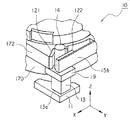
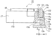
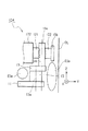
【解決手段】駆動装置(10)は、伸縮方向で互いに対向する一対の端面(13a,13b)を持つ電気機械変換素子(13)と、この電気機械変換素子の一対の端面の一方(13b)に取り付けられた振動摩擦部(14)と、この振動摩擦部と摩擦結合される移動部材(121,122)とを備える。電気機械変換素子の伸縮方向に移動部材が移動可能である。駆動装置(10)は、電気機械変換素子(13)の一対の端面の一方(13b)と振動摩擦部(14)の端面(14a)との間に配置された振動伝達部材(19)を備える。電気機械変換素子(13)の中心軸線(13O)と振動摩擦部(14)の中心軸線(14O)とは同一直線上にない。
【選択図】 図3
Description
積層圧電素子13の上端面13bは、接着剤(接着樹脂)で振動伝達部材19の下端面19aに結合(接合)され、振動摩擦部(振動部材)14の下端面14aは、接着剤(接着樹脂)で振動伝達部材19の上端面19bに結合(接合)されている。
11 静止部材
121 第1の移動体
122 第2の移動体
13 積層圧電素子(電気機械変換素子)
14 振動摩擦部
15 バネ(摩擦力付加手段、付勢手段)
15a 第1の端部
15b 第2の端部
17 可動鏡筒(レンズホルダ、レンズ支持体、被駆動部材)
170 筒状部
172 第1の突出部
174 第2の突出部
18 レンズバレル(レンズアセンブリ)
19、19A 振動伝達部材
191、192 凹部(窪み)
O レンズの光軸(被駆動部材の中心軸)
AFL オートフォーカスレンズ
Claims (12)
- 伸縮方向で互いに対向する一対の端面を持つ電気機械変換素子と、該電気機械変換素子の前記一対の端面の一方に取り付けられた振動摩擦部と、該振動摩擦部と摩擦結合される移動部材とを備え、前記電気機械変換素子の伸縮方向に前記移動部材が移動可能な駆動装置において、
前記電気機械変換素子の前記一対の端面の一方と前記振動摩擦部の端面との間に配置された振動伝達部材を備え、
前記電気機械変換素子の中心軸線と前記振動摩擦部の中心軸線とが同一直線上にないことを特徴とする駆動装置。 - 前記駆動装置は、筒状の被駆動部材をその中心軸に沿って移動させるためのものであり、
前記移動部材は、前記被駆動部材に取り付けられ、かつ前記被駆動部材の外周に近接して配置されている、請求項1に記載の駆動装置。 - 前記振動伝達部材は、前記電気機械変換素子に対して、前記被駆動部材の中心軸に近づく内側に延在しており、
前記振動摩擦部の中心軸線が前記電気機械変換素子の中心軸線よりも内側にずれている、請求項2に記載の駆動装置。 - 前記振動伝達部材は、前記電気機械変換素子に対して、前記被駆動部材の中心軸から離れる外側に延在しており、
前記振動摩擦部の中心軸線が前記電気機械変換素子の中心軸線よりも外側にずれている、請求項2に記載の駆動装置。 - 前記振動摩擦部は円柱状をしており、
前記移動部材は、前記振動摩擦部を両側から挟持する第1の移動体及び第2の移動体から構成されている、請求項2乃至4のいずれか1つに記載の駆動装置。 - 前記第1の移動体がV字型構造をしており、
前記第2の移動体が平面構造をしている、
請求項5に記載の駆動装置。 - 前記第1の移動体のV字型構造の角度は、30度から180度未満の範囲にある、請求項6に記載の駆動装置。
- 前記振動摩擦部と前記第1の移動体との間と、前記振動摩擦部と前記第2の移動体との間と、に摩擦力を発生させる摩擦力付加手段を更に備える請求項5乃至7のいずれか1つに記載の駆動装置。
- 前記摩擦力付加手段は、前記被駆動部材に第1の端部が取り付けられ、第2の端部に前記第2の移動体が取り付けられた付勢部材から構成され、該付勢部材は、前記振動摩擦部をその両側から前記第1の移動体及び前記第2の移動体により挟みながら押えるための押付力を発生する、請求項8に記載の駆動装置。
- 前記被駆動部材は、筒状部と、該筒状部から外側に突出して前記第1の移動体を保持する第1の突出部と、該第1の突出部とは異なる位置で前記筒状部から外側に突出する第2の突出部とを備え、
前記付勢部材は、前記第1の端部が前記第2の突出部に固着され、前記第2の端部に前記第2の移動体が取り付けられたバネから構成される請求項9に記載の駆動装置。 - 前記被駆動部材は、筒状部と、該筒状部から外側に突出して前記第1の移動体を兼ねる第1の突出部と、該第1の突出部とは異なる位置で前記筒状部から外側に突出する第2の突出部とを備え、
前記付勢部材は、前記第1の端部が前記第2の突出部に固着され、前記第2の端部が前記第2の移動体を兼ねるバネから構成される請求項9に記載の駆動装置。 - 前記振動伝達部材は、
前記電気機械変換素子の前記一対の端面の一方が遊嵌される第1の窪みと、
前記振動摩擦部の端面が遊嵌される第2の窪みと、
を持つ、請求項1乃至11のいずれか1つに記載の駆動装置。
Priority Applications (5)
| Application Number | Priority Date | Filing Date | Title |
|---|---|---|---|
| JP2008223561A JP5316756B2 (ja) | 2008-09-01 | 2008-09-01 | 駆動装置 |
| TW098127551A TW201014149A (en) | 2008-09-01 | 2009-08-17 | Drive device |
| CN200980133782.3A CN102138279B (zh) | 2008-09-01 | 2009-08-25 | 驱动装置 |
| US13/061,573 US8466603B2 (en) | 2008-09-01 | 2009-08-25 | Driving apparatus |
| PCT/JP2009/064791 WO2010024252A1 (ja) | 2008-09-01 | 2009-08-25 | 駆動装置 |
Applications Claiming Priority (1)
| Application Number | Priority Date | Filing Date | Title |
|---|---|---|---|
| JP2008223561A JP5316756B2 (ja) | 2008-09-01 | 2008-09-01 | 駆動装置 |
Publications (2)
| Publication Number | Publication Date |
|---|---|
| JP2010063206A true JP2010063206A (ja) | 2010-03-18 |
| JP5316756B2 JP5316756B2 (ja) | 2013-10-16 |
Family
ID=41721419
Family Applications (1)
| Application Number | Title | Priority Date | Filing Date |
|---|---|---|---|
| JP2008223561A Expired - Fee Related JP5316756B2 (ja) | 2008-09-01 | 2008-09-01 | 駆動装置 |
Country Status (5)
| Country | Link |
|---|---|
| US (1) | US8466603B2 (ja) |
| JP (1) | JP5316756B2 (ja) |
| CN (1) | CN102138279B (ja) |
| TW (1) | TW201014149A (ja) |
| WO (1) | WO2010024252A1 (ja) |
Cited By (1)
| Publication number | Priority date | Publication date | Assignee | Title |
|---|---|---|---|---|
| US8903231B2 (en) * | 2011-06-21 | 2014-12-02 | Samsung Electronics Co., Ltd. | Image stabilizing apparatus |
Families Citing this family (6)
| Publication number | Priority date | Publication date | Assignee | Title |
|---|---|---|---|---|
| US8824071B2 (en) * | 2010-09-15 | 2014-09-02 | Nikon Corporation | Lens barrel and camera |
| JP2015080286A (ja) * | 2013-10-15 | 2015-04-23 | ソニー株式会社 | 駆動装置および撮像装置 |
| DE102014014997B4 (de) * | 2014-10-09 | 2018-05-17 | Attocube Systems Ag | Haft-Gleit-Antrieb, insbesondere piezo-aktuierter Trägheitsantrieb |
| CN112987223A (zh) * | 2021-03-19 | 2021-06-18 | 陆圣 | 镜头驱动装置 |
| US12287527B2 (en) * | 2021-03-29 | 2025-04-29 | Tdk Taiwan Corp. | Optical element driving mechanism |
| CN113189736A (zh) * | 2021-06-11 | 2021-07-30 | 河南皓泽电子股份有限公司 | 镜头驱动机构 |
Citations (4)
| Publication number | Priority date | Publication date | Assignee | Title |
|---|---|---|---|---|
| JPH02261073A (ja) * | 1989-03-29 | 1990-10-23 | Sony Corp | 超音波モータ |
| JPH05191987A (ja) * | 1992-01-13 | 1993-07-30 | Ricoh Co Ltd | 超音波駆動装置 |
| JP2002119074A (ja) * | 2000-10-04 | 2002-04-19 | Minolta Co Ltd | 電気機械変換素子を使用した駆動装置 |
| JP2008197473A (ja) * | 2007-02-14 | 2008-08-28 | Mitsumi Electric Co Ltd | リニアアクチュエータ |
Family Cites Families (11)
| Publication number | Priority date | Publication date | Assignee | Title |
|---|---|---|---|---|
| JP3141714B2 (ja) | 1994-11-21 | 2001-03-05 | ミノルタ株式会社 | 電気機械変換素子を使用した駆動装置 |
| JP3218851B2 (ja) | 1994-03-29 | 2001-10-15 | ミノルタ株式会社 | 電気−機械変換素子を使用した駆動装置の駆動方法 |
| JP3801424B2 (ja) | 2000-06-27 | 2006-07-26 | トッパン・フォームズ株式会社 | 卓上カレンダー |
| JP4729904B2 (ja) | 2004-11-12 | 2011-07-20 | コニカミノルタオプト株式会社 | 駆動装置 |
| JP2006303955A (ja) | 2005-04-21 | 2006-11-02 | Konica Minolta Opto Inc | 撮像装置及び電子機器 |
| JP2006304529A (ja) | 2005-04-22 | 2006-11-02 | Konica Minolta Opto Inc | 駆動装置 |
| US20070176514A1 (en) | 2006-01-27 | 2007-08-02 | Taiwan Advanced Materials Technologies Corp. | Electromechanical actuator structure |
| JP5028905B2 (ja) * | 2006-08-11 | 2012-09-19 | コニカミノルタアドバンストレイヤー株式会社 | 駆動装置 |
| EP2019439A3 (en) * | 2007-07-26 | 2011-07-20 | Mitsumi Electric Co., Ltd. | Position detecting device capable of improving detection accuracy |
| JP2009047680A (ja) * | 2007-07-26 | 2009-03-05 | Mitsumi Electric Co Ltd | 駆動装置およびそれに使用される位置検出装置 |
| JP5376115B2 (ja) * | 2008-08-27 | 2013-12-25 | ミツミ電機株式会社 | 駆動装置の駆動方法 |
-
2008
- 2008-09-01 JP JP2008223561A patent/JP5316756B2/ja not_active Expired - Fee Related
-
2009
- 2009-08-17 TW TW098127551A patent/TW201014149A/zh unknown
- 2009-08-25 WO PCT/JP2009/064791 patent/WO2010024252A1/ja not_active Ceased
- 2009-08-25 CN CN200980133782.3A patent/CN102138279B/zh not_active Expired - Fee Related
- 2009-08-25 US US13/061,573 patent/US8466603B2/en not_active Expired - Fee Related
Patent Citations (4)
| Publication number | Priority date | Publication date | Assignee | Title |
|---|---|---|---|---|
| JPH02261073A (ja) * | 1989-03-29 | 1990-10-23 | Sony Corp | 超音波モータ |
| JPH05191987A (ja) * | 1992-01-13 | 1993-07-30 | Ricoh Co Ltd | 超音波駆動装置 |
| JP2002119074A (ja) * | 2000-10-04 | 2002-04-19 | Minolta Co Ltd | 電気機械変換素子を使用した駆動装置 |
| JP2008197473A (ja) * | 2007-02-14 | 2008-08-28 | Mitsumi Electric Co Ltd | リニアアクチュエータ |
Cited By (1)
| Publication number | Priority date | Publication date | Assignee | Title |
|---|---|---|---|---|
| US8903231B2 (en) * | 2011-06-21 | 2014-12-02 | Samsung Electronics Co., Ltd. | Image stabilizing apparatus |
Also Published As
| Publication number | Publication date |
|---|---|
| CN102138279B (zh) | 2014-01-08 |
| US8466603B2 (en) | 2013-06-18 |
| WO2010024252A1 (ja) | 2010-03-04 |
| US20110163632A1 (en) | 2011-07-07 |
| JP5316756B2 (ja) | 2013-10-16 |
| TW201014149A (en) | 2010-04-01 |
| CN102138279A (zh) | 2011-07-27 |
Similar Documents
| Publication | Publication Date | Title |
|---|---|---|
| JP5316756B2 (ja) | 駆動装置 | |
| JP5376115B2 (ja) | 駆動装置の駆動方法 | |
| JP4844769B2 (ja) | 駆動装置 | |
| US7633208B2 (en) | Driving device capable of transferring vibrations generated by an electro-mechanical transducer to a vibration friction portion with a high degree of efficiency | |
| JP5387811B2 (ja) | 駆動装置の駆動方法 | |
| US7652407B2 (en) | Driving device capable of improving a shock and vibration resistance thereof | |
| US7732982B2 (en) | Driving device capable of reducing height thereof | |
| CN103339848B (zh) | 位移构件、驱动构件、促动器及驱动装置 | |
| JP2009050142A (ja) | 駆動装置 | |
| JP2009276422A (ja) | 駆動装置 | |
| US7633209B2 (en) | Driving device capable of obtaining a stable frequency characteristic | |
| JP2009276423A (ja) | 駆動装置 | |
| JP2010091678A (ja) | 駆動装置 | |
| JP2010110127A (ja) | 駆動装置 |
Legal Events
| Date | Code | Title | Description |
|---|---|---|---|
| A621 | Written request for application examination |
Free format text: JAPANESE INTERMEDIATE CODE: A621 Effective date: 20110802 |
|
| A131 | Notification of reasons for refusal |
Free format text: JAPANESE INTERMEDIATE CODE: A131 Effective date: 20121024 |
|
| A521 | Request for written amendment filed |
Free format text: JAPANESE INTERMEDIATE CODE: A523 Effective date: 20121211 |
|
| TRDD | Decision of grant or rejection written | ||
| A01 | Written decision to grant a patent or to grant a registration (utility model) |
Free format text: JAPANESE INTERMEDIATE CODE: A01 Effective date: 20130612 |
|
| A61 | First payment of annual fees (during grant procedure) |
Free format text: JAPANESE INTERMEDIATE CODE: A61 Effective date: 20130625 |
|
| R150 | Certificate of patent or registration of utility model |
Ref document number: 5316756 Country of ref document: JP Free format text: JAPANESE INTERMEDIATE CODE: R150 Free format text: JAPANESE INTERMEDIATE CODE: R150 |
|
| LAPS | Cancellation because of no payment of annual fees |