JP2010060887A - Imaging lens - Google Patents
Imaging lens Download PDFInfo
- Publication number
- JP2010060887A JP2010060887A JP2008226920A JP2008226920A JP2010060887A JP 2010060887 A JP2010060887 A JP 2010060887A JP 2008226920 A JP2008226920 A JP 2008226920A JP 2008226920 A JP2008226920 A JP 2008226920A JP 2010060887 A JP2010060887 A JP 2010060887A
- Authority
- JP
- Japan
- Prior art keywords
- lens
- expression
- satisfying
- imaging
- imaging lens
- Prior art date
- Legal status (The legal status is an assumption and is not a legal conclusion. Google has not performed a legal analysis and makes no representation as to the accuracy of the status listed.)
- Granted
Links
Images


Classifications
-
- G—PHYSICS
- G02—OPTICS
- G02B—OPTICAL ELEMENTS, SYSTEMS OR APPARATUS
- G02B9/00—Optical objectives characterised both by the number of the components and their arrangements according to their sign, i.e. + or -
- G02B9/04—Optical objectives characterised both by the number of the components and their arrangements according to their sign, i.e. + or - having two components only
- G02B9/10—Optical objectives characterised both by the number of the components and their arrangements according to their sign, i.e. + or - having two components only one + and one - component
-
- G—PHYSICS
- G02—OPTICS
- G02B—OPTICAL ELEMENTS, SYSTEMS OR APPARATUS
- G02B13/00—Optical objectives specially designed for the purposes specified below
- G02B13/001—Miniaturised objectives for electronic devices, e.g. portable telephones, webcams, PDAs, small digital cameras
- G02B13/0015—Miniaturised objectives for electronic devices, e.g. portable telephones, webcams, PDAs, small digital cameras characterised by the lens design
- G02B13/002—Miniaturised objectives for electronic devices, e.g. portable telephones, webcams, PDAs, small digital cameras characterised by the lens design having at least one aspherical surface
- G02B13/003—Miniaturised objectives for electronic devices, e.g. portable telephones, webcams, PDAs, small digital cameras characterised by the lens design having at least one aspherical surface having two lenses
Landscapes
- Physics & Mathematics (AREA)
- General Physics & Mathematics (AREA)
- Optics & Photonics (AREA)
- Lenses (AREA)
Abstract
Description
本発明は、撮像レンズに係り、特に、携帯型のコンピュータ、テレビ電話、携帯電話等に搭載されるCCD、CMOS等の固体撮像素子の撮像面に、風景や人物等の物体の像を結像させる撮像装置に用いられ、小型軽量化および光学性能の向上を図ることを可能とした2枚レンズ構成の撮像レンズに関する。 The present invention relates to an imaging lens, and in particular, forms an image of an object such as a landscape or a person on an imaging surface of a solid-state imaging device such as a CCD or CMOS mounted on a portable computer, a videophone, a cellular phone, or the like. The present invention relates to an imaging lens having a two-lens configuration that can be used in an imaging device that can be reduced in size and weight and can improve optical performance.
近年、例えば、携帯電話、携帯型のコンピュータやテレビ電話等に搭載するためのCCD、CMOS等の固体撮像素子を利用したカメラの需要が著しく高まっている。このようなカメラは、限られた設置スペースに搭載する必要があることから、小型であり、かつ、軽量であることが望まれている。 In recent years, for example, a demand for a camera using a solid-state imaging device such as a CCD or a CMOS to be mounted on a mobile phone, a portable computer, a video phone, or the like has increased remarkably. Since such a camera needs to be mounted in a limited installation space, it is desired that the camera be small and lightweight.
さらに、最近においては、100万画素を超えるような高解像度の固体撮像素子の解像能力を十分に発揮させることが可能な良好な光学性能を有するレンズ系が求められており、小型軽量化と光学性能の向上とをバランスさせることが益々重要になっている。 Furthermore, recently, there has been a demand for a lens system having good optical performance capable of sufficiently exerting the resolution capability of a solid-state imaging device having a high resolution exceeding 1 million pixels. Balancing the improvement in optical performance is becoming increasingly important.
このような観点からは、3枚構成のレンズ系よりも小型軽量化に優れ、1枚構成のレンズ系よりも光学性能に優れた2枚構成のレンズ系が有利であり、これまでにも、このような2枚構成のレンズ系としては、例えば、特許文献1〜5に示すようなレンズ系が提案されている。
From this point of view, a two-lens lens system that is superior in size and weight than a three-lens lens system and superior in optical performance than a single-lens lens system is advantageous. As such a two-lens configuration, for example, lens systems as shown in
しかしながら、特許文献1〜3に記載のレンズ系は、いずれも、第2レンズが正のパワーを持つレンズとされており、第1レンズとのパワーの組み合わせによる効果的な収差補正が困難であるといった欠点を有している。
However, in any of the lens systems described in
さらに、特許文献4〜6に記載のレンズ系は、第1レンズの物体側の面と像面側の面との曲率のバランスが悪く、小型軽量化と良好な光学性能の維持とを両立させることが困難であるといった欠点を有している。
Furthermore, the lens systems described in
そこで、本発明はこのような問題に鑑みなされたもので、小型軽量化を図りつつ光学性能を向上させることができる撮像レンズを提供することを目的とするものである。 Therefore, the present invention has been made in view of such problems, and an object thereof is to provide an imaging lens capable of improving optical performance while achieving reduction in size and weight.
前述した目的を達成するため、本発明の請求項1に係る撮像レンズの特徴は、固体撮像素子の撮像面に物体の像を結像させるために使用される撮像レンズであって、物体側から像面側に向かって順に、絞り、物体側に凸面を向けた正のパワーを有するメニスカスレンズとされた第1レンズ、および物体側に凹面を向けた負のパワーを有するレンズとされた第2レンズを配設し、次の(1)に示す条件式、
0.05≦r1/r2≦0.29 (1)
但し、
r1:第1レンズの物体側の面の中心曲率半径
r2:第1レンズの像面側の面の中心曲率半径
を満足する点にある。
In order to achieve the above-described object, a feature of the imaging lens according to
0.05 ≦ r 1 / r 2 ≦ 0.29 (1)
However,
r 1 : the center curvature radius of the object-side surface of the first lens r 2 : the center curvature radius of the image-side surface of the first lens.
なお、本発明において、絞りを最も物体側に配置することは、絞りを第1レンズの物体側の面(凸面)の光軸上の点(以下、面頂と称する)と光軸方向における同一の位置に配置すること、または、第1レンズの物体側の面の面頂およびその近傍部分が絞りを通して絞りよりも物体側に位置(突出)することを妨げない。その場合であっても、物理的な配置としては絞りが第1レンズ全体よりも物体側に配置されるといえるので、特許請求の範囲の記載に反するものとはならない。また、光学系の小型化のためには、絞りが第1レンズの物体側の面の面頂よりも像面側にあることが望ましい。 In the present invention, disposing the stop closest to the object side means that the stop is the same in the optical axis direction as a point on the optical axis of the object side surface (convex surface) of the first lens (hereinafter referred to as the surface apex). Or the top of the surface of the first lens on the object side and the vicinity thereof are not prevented from being positioned (projected) to the object side of the stop through the stop. Even in such a case, as a physical arrangement, it can be said that the diaphragm is arranged on the object side with respect to the entire first lens, and this does not contradict the description of the claims. In order to reduce the size of the optical system, it is desirable that the stop is located on the image plane side of the top of the object side surface of the first lens.
そして、この請求項1に係る発明によれば、最も物体側に絞りを配置し、第1レンズを物体側に凸の正メニスカスレンズに形成し、第2レンズを物体側に凹面を向けた負レンズに形成し、(1)の条件式を満たすようにすることにより、小型軽量化を図りつつ、テレセントリック性を確保し、収差を有効に補正して光学性能を向上させることが可能となる。 According to the first aspect of the present invention, the aperture is arranged closest to the object side, the first lens is formed as a positive meniscus lens convex toward the object side, and the second lens is negative with the concave surface facing the object side. By forming the lens on the lens so as to satisfy the conditional expression (1), it is possible to improve the optical performance by ensuring the telecentricity and effectively correcting the aberration while reducing the size and weight.
また、請求項2に係る撮像レンズの特徴は、請求項1において、更に、次の(2)に示す条件式、
0.4≦r1/FL≦0.5 (2)
但し、
FL:レンズ系全体の焦点距離
を満足する点にある。
The imaging lens according to
0.4 ≦ r 1 /FL≦0.5 (2)
However,
FL: The lens system satisfies the focal length of the entire lens system.
そして、この請求項2に係る発明によれば、更に(2)の条件式を満たすようにすることにより、小型軽量化、光学性能の向上、および製造性の向上を良好にバランスさせることが可能となる。なお、製造性とは、撮像レンズを大量生産する場合の製造性(例えば、射出成形により、撮像レンズを大量生産する場合の成形性やコスト等)である意の他、撮像レンズを製造するために使用される設備の加工、製作等の容易性(例えば、射出成形に用いる金型の加工の容易性等)である意も含む(以下、同様)。 According to the second aspect of the invention, by further satisfying the conditional expression (2), it is possible to satisfactorily balance reduction in size and weight, improvement in optical performance, and improvement in manufacturability. It becomes. Note that manufacturability refers to manufacturability when mass-producing imaging lenses (for example, moldability and cost when mass-producing imaging lenses are produced by injection molding), and for manufacturing imaging lenses. It also includes the meaning of the ease of processing, production, etc. of the equipment used in (for example, the ease of processing of the mold used for injection molding) (hereinafter the same).
さらに、請求項3に係る撮像レンズの特徴は、請求項1または2において、更に、次の(3)に示す条件式、
0.85≦f1/FL≦1 (3)
但し、
f1:第1レンズの焦点距離
FL:レンズ系全体の焦点距離
を満足する点にある。
Further, the imaging lens according to
0.85 ≦ f 1 / FL ≦ 1 (3)
However,
f 1 : The focal length of the first lens FL: The focal length of the entire lens system is satisfied.
そして、この請求項3に係る発明によれば、更に(3)の条件式を満たすようにすることにより、小型軽量化と光学性能の向上とを更に良好にバランスさせることが可能となる。 According to the third aspect of the invention, by further satisfying the conditional expression (3), it is possible to achieve a better balance between reduction in size and weight and improvement in optical performance.
さらにまた、請求項4に係る撮像レンズの特徴は、請求項1〜3のいずれか1項において、更に、次の(4)に示す条件式、
0.65≦d2/d1≦1.25 (4)
但し、
d1:第1レンズの中心厚
d2:光軸上における第1レンズと第2レンズとの間隔
を満足する点にある。
Furthermore, the imaging lens according to
0.65 ≦ d 2 / d 1 ≦ 1.25 (4)
However,
d 1 : center thickness of the first lens d 2 : the distance between the first lens and the second lens on the optical axis is satisfied.
そして、この請求項4に係る発明によれば、更に(4)の条件式を満たすようにすることにより、製造性を維持しつつ不要光を有効に遮蔽するための手段を適切に講じることが可能となる。
According to the invention of
また、請求項5に係る撮像レンズの特徴は、請求項1〜4のいずれか1項において、更に、次の(5)に示す条件式、
0.65≦d2/d3≦1.1 (5)
但し、
d2:光軸上における第1レンズと第2レンズとの間隔
d3:第2レンズの中心厚
を満足する点にある。
The imaging lens according to
0.65 ≦ d 2 / d 3 ≦ 1.1 (5)
However,
d 2 : the distance between the first lens and the second lens on the optical axis d 3 : the center thickness of the second lens is satisfied.
そして、この請求項5に係る発明によれば、更に(5)の条件を満たすようにすることにより、製造性を確保しつつ不要光を効果的に遮蔽するための手段を適切に講じることが可能となる。 According to the fifth aspect of the invention, by satisfying the condition (5), it is possible to appropriately take measures for effectively shielding unnecessary light while ensuring manufacturability. It becomes possible.
さらに、請求項6に係る撮像レンズの特徴は、請求項1〜5のいずれか1項において、更に、次の(6)に示す条件式、
0.1≦d1/FL≦0.3 (6)
但し、
d1:第1レンズの中心厚
FL:レンズ系全体の焦点距離
を満足する点にある。
Further, the imaging lens according to
0.1 ≦ d 1 /FL≦0.3 (6)
However,
d 1 : Center thickness of the first lens FL: The focal length of the entire lens system is satisfied.
そして、この請求項6に係る発明によれば、更に(6)の条件式を満たすようにすることにより、小型軽量化と製造性の維持とを良好にバランスさせることが可能となる。 According to the sixth aspect of the present invention, it is possible to satisfactorily balance the reduction in size and weight with the maintenance of manufacturability by further satisfying the conditional expression (6).
さらにまた、請求項7に係る撮像レンズの特徴は、請求項1〜6のいずれか1項において、更に、次の(7)に示す条件式、
0.1≦d3/FL≦0.3 (7)
但し、
d3:第2レンズの中心厚
FL:レンズ系全体の焦点距離
を満足する点にある。
Still further, the imaging lens according to claim 7 is characterized in that in any one of
0.1 ≦ d 3 /FL≦0.3 (7)
However,
d 3 : Center thickness of the second lens FL: The focal length of the entire lens system is satisfied.
そして、この請求項7に係る発明によれば、更に(7)の条件式を満たすようにすることにより、小型軽量化を図りつつ製造性を維持することが可能となる。 And according to this invention concerning Claim 7, it becomes possible to maintain manufacturability, aiming at size reduction and weight reduction by satisfying the conditional expression of (7) further.
また、請求項8に係る撮像レンズの特徴は、請求項1〜7のいずれか1項において、更に、次の(8)に示す条件式、
0.9≦L/FL≦1.2 (8)
但し、
L:レンズ系の全長(最も物体側の面から撮像面までの光軸上の距離:空気換算長)
FL:レンズ系全体の焦点距離
を満足する点にある。
Further, the imaging lens according to
0.9 ≦ L / FL ≦ 1.2 (8)
However,
L: Total length of the lens system (distance on the optical axis from the most object-side surface to the imaging surface: air conversion length)
FL: The lens system satisfies the focal length of the entire lens system.
そして、この請求項8に係る発明によれば、更に(8)の条件式を満たすようにすることにより、小型軽量化と製造性の維持とのバランスを取ることができる。 According to the eighth aspect of the invention, by further satisfying the conditional expression (8), it is possible to balance the reduction in size and weight with the maintenance of manufacturability.
本発明の撮像レンズによれば、小型軽量化を図りつつ光学性能を向上させることができる。 According to the imaging lens of the present invention, it is possible to improve the optical performance while reducing the size and weight.
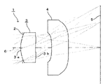
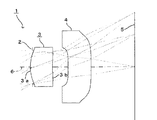
以下、本発明に係る撮像レンズの実施形態について、図1を参照して説明する。 Hereinafter, an embodiment of an imaging lens according to the present invention will be described with reference to FIG.
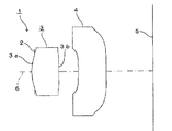
本実施形態における撮像レンズ1は、図1に示すように、物体側から像面側に向かって順に、絞り2と、物体側に凸面を向けた正のパワーを有するメニスカスレンズとされた樹脂製の第1レンズ3と、物体側に凹面を向けた負のパワーを有するレンズとされた樹脂製の第2レンズ4とを有している。
As shown in FIG. 1, the
以下、第1レンズ3および第2レンズ4における物体側および像面側の各レンズ面を、それぞれ第1面、第2面と称することとする。
Hereinafter, the object-side and image-side lens surfaces of the
また、第2レンズ4の第2面側には、CCDあるいはCMOS等の固体撮像素子の受光面である撮像面5が配設されている。
An
なお、第2レンズ4の第2面と撮像面5との間に、必要に応じてカバーガラス、IRカットフィルタ、ローパスフィルタ等の各種フィルタを配置してもよい。また、第1レンズ3、第2レンズ4の各レンズ面のうち、第1レンズ3の第2面3b等のいずれか1つのレンズ面または複数のレンズ面にIRカットフィルタを形成してもよい。
Various filters such as a cover glass, an IR cut filter, and a low-pass filter may be disposed between the second surface of the
このように、本実施形態においては、絞り2を最も物体側に配置して射出瞳位置を撮像面5から遠くに位置させることによって高いテレセントリック性を確保することができるため、固体撮像素子のセンサに対する光線の入射角度を緩和することができる。
As described above, in the present embodiment, since the
また、本実施形態においては、物体側に凸の正メニスカスレンズとされた第1レンズ3に対して、第2レンズ4が負のパワーのレンズであることにより、第1レンズ3とのパワーの組み合わせによる効果的な収差補正が可能となる。
In the present embodiment, the
さらに、本実施形態においては、次の(1)に示す条件式を満足するようにする。 Furthermore, in the present embodiment, the conditional expression shown in the following (1) is satisfied.
0.05≦r1/r2≦0.29 (1)
但し、(1)式におけるr1は、第1レンズ3の第1面3aの中心曲率半径である(以下、同様)。また、(1)式におけるr2は、第1レンズ3の第2面3bの中心曲率半径である(以下、同様)。
0.05 ≦ r 1 / r 2 ≦ 0.29 (1)
However, (1) r 1 in the expression is the center radius curvature of the first face 3a of the first lens 3 (the same applies hereinafter). Further, r 2 in the expression (1) is a central radius of curvature of the
ここで、r1/r2の値が(1)式に示す値(0.05)よりも小さくなると、第1レンズ3の第2面3bにおける収差補正効果が弱くなり、光学系全体の小型軽量化を確保しながら所望の光学性能を得ることが困難となる。一方、r1/r2の値が(1)式に示す値(0.29)よりも大きくなると、第1レンズ3の第1面3aおよび第2面3bの双方の中心曲率半径が小さくなり過ぎることになり、第1レンズ3を射出成形によって製造する場合における射出成形用金型の製造が困難となり、光学系全体の小型軽量化を確保することができなくなる。
Here, if the value of r 1 / r 2 is smaller than the value (0.05) shown in the equation (1), the aberration correction effect on the
したがって、本実施形態によれば、r1/r2の値を(1)の条件式を満たすようにすることにより、小型軽量化を図りつつ、製造性を確保し、収差を有効に補正して光学性能を向上させることが可能となる。 Therefore, according to the present embodiment, by satisfying the conditional expression (1) for the value of r 1 / r 2 , manufacturability is ensured and aberration is effectively corrected while reducing the size and weight. Thus, the optical performance can be improved.
なお、このr1とr2との関係は、0.1≦r1/r2≦0.25とされることが、より好ましい。 The relationship between r 1 and r 2 is more preferably 0.1 ≦ r 1 / r 2 ≦ 0.25.
より好ましい実施形態としては、更に、次の(2)に示す条件式を満足するようにする。 As a more preferred embodiment, the conditional expression (2) below is further satisfied.
0.4≦r1/FL≦0.5 (2)
但し、(2)式におけるFLは、レンズ系全体の焦点距離である(以下、同様)。
0.4 ≦ r 1 /FL≦0.5 (2)
However, FL in equation (2) is the focal length of the entire lens system (the same applies hereinafter).
ここで、r1/FLの値が(2)式に示す値(0.4)よりも小さくなると、第1レンズ3の中心曲率半径が小さくなり過ぎることになり、第1レンズ3の製造が困難となる。一方、r1/FLの値が(2)式に示す値(0.5)よりも大きくなると、光学系全体が大きくなり過ぎることになり、小型軽量化が困難となる。
Here, if the value of r 1 / FL is smaller than the value (0.4) shown in the equation (2), the central radius of curvature of the
したがって、r1/FLの値を(2)の条件式を満たすようにすれば、小型軽量化、光学性能の向上、および製造性の向上を良好にバランスさせることが可能となる。 Therefore, if the value of r 1 / FL is satisfied to satisfy the conditional expression (2), it is possible to satisfactorily balance reduction in size and weight, improvement in optical performance, and improvement in manufacturability.
なお、r1とFLとの関係は、0.4≦r1/FL≦0.48とされることが、より好ましい。 The relationship between r 1 and FL is more preferably 0.4 ≦ r 1 /FL≦0.48.
より好ましい実施形態としては、更に、次の(3)に示す条件式を満足するようにする。 As a more preferred embodiment, the conditional expression (3) below is further satisfied.
0.85≦f1/FL≦1 (3)
但し、(3)式におけるf1は、第1レンズ3の焦点距離である(以下、同様)。
0.85 ≦ f 1 / FL ≦ 1 (3)
However, (3) f 1 in the expression is the focal length of the first lens 3 (the same applies hereinafter).
ここで、f1/FLの値が(3)式に示す値(0.85)よりも小さくなると、光学系全体のパワーに比して第1レンズ3のパワーが大きくなり過ぎることになり、所望の光学性能を得ることが困難となる。一方、f1/FLの値が(3)式に示す値(1)よりも大きくなると、光学系全体のパワーに比して第1レンズ3のパワーが小さくなり過ぎることになり、光学系全体の小型軽量化が困難となる。
Here, when the value of f 1 / FL is smaller than the value (0.85) shown in the equation (3), the power of the
したがって、f1/FLの値を(3)の条件式を満たすようにすれば、小型軽量化と光学性能の向上とを更に良好にバランスさせることが可能となる。 Therefore, if the value of f 1 / FL is set to satisfy the conditional expression (3), it is possible to better balance between reduction in size and weight and improvement in optical performance.
なお、f1とFLとの関係は、0.9≦f1/FL≦1とされることが、より好ましい。 The relationship between f 1 and FL is more preferably 0.9 ≦ f 1 / FL ≦ 1.
より好ましい実施形態としては、更に、次の(4)に示す条件式を満足するようにする。 As a more preferred embodiment, the conditional expression (4) below is further satisfied.
0.65≦d2/d1≦1.25 (4)
但し、(4)式におけるd1は、第1レンズ3の中心厚である(以下、同様)。また、(4)式におけるd2は、光軸6上における第1レンズ3と第2レンズ4との間隔である(以下、同様)。
0.65 ≦ d 2 / d 1 ≦ 1.25 (4)
However, d 1 in (4) is the center thickness of the first lens 3 (the same applies hereinafter). Further, d 2 in the expression (4) is the distance between the
ここで、d2/d1の値が(4)式に示す値(0.65)よりも小さくなると、第1レンズ3と第2レンズ4との間の間隔が狭くなり、第1レンズ3と第2レンズ4との間に不要光を有効に遮蔽するための遮蔽板等を挿入することが困難となる。また、第1レンズ3、第2レンズ4のそれぞれの光学面のエッジ部が互いに接近し過ぎることになり、不要光の発生を助長することとなる。一方、d2/d1の値が(4)式に示す値(1.25)よりも大きくなると、第1レンズ3の中心厚が小さくなり過ぎることになり、第1レンズ3を射出成形によって製造する場合における第1レンズ3の製造が困難となる。
Here, when the value of d 2 / d 1 becomes smaller than the value (0.65) shown in the equation (4), the interval between the
したがって、d2/d1の値を(4)の条件式を満たすようにすれば、製造性を維持しつつ不要光を有効に遮蔽するための手段を適切に講じることが可能となる。 Therefore, if the value of d 2 / d 1 is made to satisfy the conditional expression (4), it is possible to appropriately take measures for effectively shielding unnecessary light while maintaining manufacturability.
なお、d1とd2との関係は、0.7≦d2/d1≦1.2とされることが、より好ましい。 It is more preferable that the relationship between d 1 and d 2 is 0.7 ≦ d 2 / d 1 ≦ 1.2.
より好ましい実施形態としては、更に、次の(5)に示す条件式を満足するようにする。 As a more preferred embodiment, the conditional expression (5) below is further satisfied.
0.65≦d2/d3≦1.1 (5)
但し、(5)式におけるd3は、第2レンズ4の中心厚である(以下、同様)。
0.65 ≦ d 2 / d 3 ≦ 1.1 (5)
However, (5) d 3 in the expression is the center thickness of the second lens 4 (the same applies hereinafter).
ここで、d2/d3の値が(5)式に示す値(0.65)よりも小さくなると、第1レンズ3と第2レンズ4との間の間隔が狭くなり、第1レンズ3と第2レンズ4との間に不要光を効果的に遮蔽するための遮蔽板等を挿入することが困難となる。また、第1レンズ3、第2レンズ4のそれぞれの光学面のエッジ部が互いに接近し過ぎることになり、不要光の発生を助長することとなる。一方、d2/d3の値が(5)式に示す値(1.1)よりも大きくなると、第2レンズ4の中心厚が小さくなり過ぎることになり、第2レンズ4を射出成形によって製造する場合における第2レンズ4の製造が困難となる。
Here, when the value of d 2 / d 3 becomes smaller than the value (0.65) shown in the equation (5), the interval between the
したがって、d2/d3の値を(5)の条件式を満たすようにすれば、製造性を確保しつつ不要光を効果的に遮蔽するための手段を適切に講じることが可能となる。 Therefore, if the value of d 2 / d 3 is made to satisfy the conditional expression (5), it is possible to appropriately take measures for effectively shielding unnecessary light while ensuring manufacturability.
なお、d2とd3との関係は、0.65≦d2/d3≦1とされることが、より好ましい。 The relationship between d 2 and d 3 is more preferably 0.65 ≦ d 2 / d 3 ≦ 1.
より好ましい実施形態としては、更に、次の(6)に示す条件式を満足するようにする。 As a more preferred embodiment, the following conditional expression (6) is further satisfied.
0.1≦d1/FL≦0.3 (6)
ここで、d1/FLの値が(6)式に示す値(0.1)よりも小さくなると、第1レンズ3の中心厚が小さくなり過ぎることになり、第1レンズ3を射出成形によって製造する場合における第1レンズ3の製造が困難となる。一方、d1/FLの値が(6)式に示す値(0.3)よりも大きくなると、光学系の全長に比して第1レンズ3の中心厚が大きくなり過ぎることになり、小型軽量化が困難となる。
0.1 ≦ d 1 /FL≦0.3 (6)
Here, when the value of d 1 / FL becomes smaller than the value (0.1) shown in the equation (6), the center thickness of the
したがって、d1/FLの値を(6)の条件式を満たすようにすれば、小型軽量化と製造性の維持とをさらに良好にバランスさせることが可能となる。 Therefore, if the value of d 1 / FL satisfies the conditional expression (6), it is possible to better balance the reduction in size and weight and the maintenance of manufacturability.
なお、d1とFLとの関係は、0.15≦d1/FL≦0.27とされることが、より好ましい。 The relationship between d 1 and FL is more preferably 0.15 ≦ d 1 /FL≦0.27.
より好ましい実施形態としては、更に、次の(7)に示す条件式を満足するようにする。 As a more preferred embodiment, the following conditional expression (7) is further satisfied.
0.1≦d3/FL≦0.3 (7)
ここで、d3/FLの値が(7)式に示す値(0.1)よりも小さくなると、第2レンズ4の中心厚が小さくなり過ぎることになり、第2レンズ4を射出成形によって製造する場合における第2レンズ4の製造が困難となる。一方、d3/FLの値が(7)式に示す値(0.3)よりも大きくなると、光学系の全長に比して第2レンズ4の中心厚が大きくなり過ぎることになり、小型軽量化が困難となる。
0.1 ≦ d 3 /FL≦0.3 (7)
Here, when the value of d 3 / FL becomes smaller than the value (0.1) shown in the equation (7), the center thickness of the
したがって、d3/FLの値を(7)の条件式を満たすようにすれば、さらに有効に小型軽量化を図りつつ製造性を維持することが可能となる。 Therefore, if the value of d 3 / FL is set to satisfy the conditional expression (7), it is possible to maintain manufacturability while further reducing the size and weight.
なお、d3とFLとの関係は、0.15≦d3/FL≦0.27とされることが、より好ましい。 The relationship between d 3 and FL is more preferably 0.15 ≦ d 3 /FL≦0.27.
より好ましい実施形態としては、更に、次の(8)に示す条件式を満足するようにする。 As a more preferred embodiment, the conditional expression (8) below is further satisfied.
0.9≦L/FL≦1.2 (8)
但し、(8)式におけるLは、レンズ系の全長、すなわち、最も物体側の面から撮像面5までの光軸6上の距離(空気換算長)である(以下、同様)。
0.9 ≦ L / FL ≦ 1.2 (8)
However, L in the equation (8) is the total length of the lens system, that is, the distance (air conversion length) on the
ここで、L/FLの値が(8)式に示す値(0.9)よりも小さくなると、光学系の全長が小さくなり過ぎることになり、各レンズ3、4を組み立てる工程における製造性が低下することとなる。一方、L/FLの値が(8)式に示す値(1.2)よりも大きくなると、光学系の全長が大きくなり過ぎることになり、携帯電話機等の小型カメラに搭載することが困難となる。
Here, if the value of L / FL becomes smaller than the value (0.9) shown in the equation (8), the total length of the optical system becomes too small, and the manufacturability in the process of assembling the
したがって、L/FLの値を(8)の条件式を満たすようにすれば、さらに有効に小型軽量化と製造性の維持とのバランスを取ることができる。 Therefore, if the L / FL value satisfies the conditional expression (8), it is possible to more effectively balance the reduction in size and weight with the maintenance of manufacturability.
なお、LとFLとの関係は、0.95≦L/FL≦1.15とされることが、より好ましい。 The relationship between L and FL is more preferably 0.95 ≦ L / FL ≦ 1.15.
さらに、第1レンズ3および第2レンズ4を成形するための樹脂材料は、アクリル、ポリカーボネート、非晶質ポリオレフィン樹脂等、光学部品の成形に用いられる透明性を有するものであればどのような組成を有するものであってもよいが、製造効率のさらなる向上および製造コストのさらなる低廉化の観点からは、両レンズ3、4の樹脂材料を同一の樹脂材料に統一することが望ましい。
Further, the resin material for molding the
次に、本発明の実施例について、図2乃至図39を参照して説明する。 Next, an embodiment of the present invention will be described with reference to FIGS.
ここで、本実施例において、Fnoは、Fナンバー、r は、光学面の曲率半径(レンズの場合は中心曲率半径)を示す。また、dは、次の光学面までの光軸6上の距離を示す。また、ndは、d線(黄色)を照射した場合における各光学系の屈折率、νdは、同じくd線の場合における各光学系のアッベ数を示す。
Here, in this embodiment, Fno is the F number, r Indicates the radius of curvature of the optical surface (in the case of a lens, the center radius of curvature). D represents the distance on the
k、A、B、C、Dは、次の(9)式における各係数を示す。すなわち、レンズの非球面の形状は、光軸6方向にZ軸、光軸6に直交する方向にX軸をとり、光の進行方向を正とし、kを円錐係数、A、B、C、Dを非球面係数、rを曲率半径としたとき次式で表される。
k, A, B, C, and D indicate coefficients in the following equation (9). That is, the aspherical shape of the lens is such that the Z axis is in the direction of the
Z(X)=r−1 X2 /[1+{1−(k+1)r−2 X2 }1/2 ]
+AX4 +BX6 +CX8 +DX10 (9)
Z (X) = r -1 X 2 / [1+ {1- (k + 1) r -2 X 2} 1/2]
+ AX 4 + BX 6 + CX 8 + DX 10 (9)
また、以下の実施例において、円錐係数および非球面係数を表す数値に用いられる記号Eは、その次に続く数値が10を底としたべき指数であることを示し、その10を底としたべき指数で表される数値が、Eの前の数値に乗算されることを示す。例えば、−2.18E+3は、−2.18×10³であることを示す。 Further, in the following examples, the symbol E used for the numerical values representing the conic coefficient and the aspherical coefficient indicates that the subsequent numerical value is an exponent that should be base 10, and that 10 should be base. Indicates that the numerical value represented by the exponent is multiplied by the numerical value before E. For example, -2.18E + 3 indicates -2.18 × 10 3 .
<第1実施例>
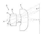
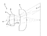
図2は、本発明の第1実施例を示したものであり、本実施例のレンズ1は、図1に示した構成のレンズ1と同一のレンズ1である。本実施例においては、第1レンズ3の第1面3aの面頂(光軸6との交点)およびその近傍部分が絞り2を通して最も物体側に位置している。
<First embodiment>
FIG. 2 shows a first embodiment of the present invention. The
この第1実施例の撮像レンズ1は、以下の条件に設定されている。
レンズデータ
L=1.65mm、FL=1.45mm、f1=1.332mm、f2=−9.764mm、Fno=2.8
面番号 r d nd νd
(物点)
1(絞り) ∞ -0.040
2(第1レンズ第1面) 0.680 0.370 1.531 56.0
3(第1レンズ第2面) 13.000 0.265
4(第2レンズ第1面) -5.500 0.380 1.531 56.0
5(第2レンズ第2面) 100.000
(像面)
面番号 k A B C D
2 0 -2.10 7.86E+1 -2.18E+3 2.95E+4
3 0 -1.31 -2.46E+1 2.98E+1 2.31E+3
4 0 -5.76E-1 -1.68E+2 3.93E+3 -5.87E+4
5 0 -7.14E-1 -3.26 -1.33E+1 2.17E+2
The
Lens data
L = 1.65 mm, FL = 1.45 mm, f 1 = 1.332 mm, f 2 = −9.764 mm, Fno = 2.8
Surface number r d nd νd
(Object point)
1 (Aperture) ∞ -0.040
2 (first surface of the first lens) 0.680 0.370 1.531 56.0
3 (1st lens 2nd surface) 13.000 0.265
4 (2nd lens 1st surface) -5.500 0.380 1.531 56.0
5 (2nd surface of the second lens) 100.000
(Image plane)
Surface number k A B C D
2 0 -2.10 7.86E + 1 -2.18E + 3 2.95E + 4
3 0 -1.31 -2.46E + 1 2.98E + 1 2.31E + 3
4 0 -5.76E-1 -1.68E + 2 3.93E + 3 -5.87E + 4
5 0 -7.14E-1 -3.26 -1.33E + 1 2.17E + 2
このような条件の下で、r1/r2=0.052となり、(1)式を満足するものであった。また、r1/FL=0.469となり、(2)式を満足するものであった。さらに、f1/FL=0.919となり、(3)式を満足するものであった。さらにまた、d2/d1=0.72となり、(4)式を満足するものであった。また、d2/d3=0.70となり、(5)式を満足するものであった。さらに、d1/FL=0.26となり、(6)式を満足するものであった。さらにまた、d3/FL=0.26となり、(7)式を満足するものであった。また、L/FL=1.138となり、(8)式を満足するものであった。 Under such conditions, r 1 / r 2 = 0.052 was achieved, thereby satisfying the expression (1). R 1 /FL=0.469 was achieved, thereby satisfying the expression (2). F 1 /FL=0.919 was achieved, thereby satisfying the expression (3). D 2 / d 1 = 0.72 was achieved, thereby satisfying the expression (4). D 2 / d 3 = 0.70 was achieved, thereby satisfying the expression (5). D 1 /FL=0.26 was achieved, thereby satisfying the expression (6). D 3 /FL=0.26 was achieved, thereby satisfying the expression (7). L / FL = 1.138 was achieved, thereby satisfying the expression (8).
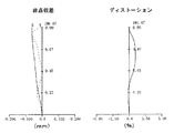
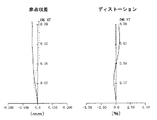
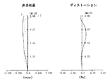
この第1実施例の撮像レンズ1における非点収差およびディストーションを図3に示す。
FIG. 3 shows astigmatism and distortion in the
この結果によれば、非点収差およびディストーションのいずれもほぼ満足できる結果となり、充分な光学特性を得ることができることが分かる。 According to this result, it can be seen that both astigmatism and distortion are almost satisfactory, and sufficient optical characteristics can be obtained.
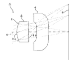
<第2実施例>
図4は、本発明の第2実施例を示したものであり、本実施例においても、第1レンズ3の第1面3aの面頂およびその近傍部分が絞り2を通して最も物体側に位置している。
<Second embodiment>
FIG. 4 shows a second embodiment of the present invention. Also in this embodiment, the top surface of the first surface 3a of the
この第2実施例の撮像レンズ1は、以下の条件に設定されている。
レンズデータ
L=1.65mm、FL=1.427mm、f1=1.337mm、f2=−14.36mm、Fno=2.8
面番号 r d nd νd
(物点)
1(絞り) ∞ -0.040
2(第1レンズ第1面) 0.680 0.370 1.531 56.0
3(第1レンズ第2面) 12.000 0.265
4(第2レンズ第1面) -5.500 0.380 1.531 56.0
5(第2レンズ第2面) -20.000
(像面)
面番号 k A B C D
2 0 -2.10 7.90E+1 -2.18E+3 2.95E+4
3 0 -1.21 -2.46E+1 4.19E+1 2.16E+3
4 0 -3.69E-1 -1.68E+2 3.90E+3 -5.83E+4
5 0 -5.95E-1 -3.88 -1.09E+1 2.13E+2
The
Lens data
L = 1.65 mm, FL = 1.427 mm, f 1 = 1.337 mm, f 2 = −14.36 mm, Fno = 2.8
Surface number r d nd νd
(Object point)
1 (Aperture) ∞ -0.040
2 (first surface of the first lens) 0.680 0.370 1.531 56.0
3 (1st lens 2nd surface) 12.000 0.265
4 (2nd lens 1st surface) -5.500 0.380 1.531 56.0
5 (2nd surface of the second lens) -20.000
(Image plane)
Surface number k A B C D
2 0 -2.10 7.90E + 1 -2.18E + 3 2.95E + 4
3 0 -1.21 -2.46E + 1 4.19E + 1 2.16E + 3
4 0 -3.69E-1 -1.68E + 2 3.90E + 3 -5.83E + 4
5 0 -5.95E-1 -3.88 -1.09E + 1 2.13E + 2
このような条件の下で、r1/r2=0.057となり、(1)式を満足するものであった。また、r1/FL=0.477となり、(2)式を満足するものであった。さらに、f1/FL=0.937となり、(3)式を満足するものであった。さらにまた、d2/d1=0.72となり、(4)式を満足するものであった。また、d2/d3=0.70となり、(5)式を満足するものであった。さらに、d1/FL=0.26となり、(6)式を満足するものであった。さらにまた、d3/FL=0.27となり、(7)式を満足するものであった。また、L/FL=1.156となり、(8)式を満足するものであった。 Under such conditions, r 1 / r 2 = 0.057 was achieved, thereby satisfying the expression (1). R 1 /FL=0.477 was achieved, thereby satisfying the expression (2). F 1 /FL=0.937 was achieved, thereby satisfying the expression (3). D 2 / d 1 = 0.72 was achieved, thereby satisfying the expression (4). D 2 / d 3 = 0.70 was achieved, thereby satisfying the expression (5). D 1 /FL=0.26 was achieved, thereby satisfying the expression (6). D 3 /FL=0.27 was achieved, thereby satisfying the expression (7). L / FL = 1.156 was achieved, thereby satisfying the expression (8).
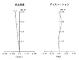
この第2実施例の撮像レンズ1における非点収差およびディストーションを図5に示す。
FIG. 5 shows astigmatism and distortion in the
この結果によれば、非点収差およびディストーションのいずれもほぼ満足できる結果となり、充分な光学特性を得ることができることが分かる。 According to this result, it can be seen that both astigmatism and distortion are almost satisfactory, and sufficient optical characteristics can be obtained.
<第3実施例>
図6は、本発明の第3実施例を示したものであり、本実施例においても、第1レンズ3の第1面3aの面頂およびその近傍部分が絞り2を通して最も物体側に位置している。
<Third embodiment>
FIG. 6 shows a third embodiment of the present invention. In this embodiment as well, the top of the first surface 3a of the
この第3実施例の撮像レンズ1は、以下の条件に設定されている。
レンズデータ
L=1.36mm、FL=1.2mm、f1=1.1mm、f2=−8.067mm、Fno=2.8
面番号 r d nd νd
(物点)
1(絞り) ∞ -0.030
2(第1レンズ第1面) 0.550 0.300 1.531 56.0
3(第1レンズ第2面) 7.100 0.210
4(第2レンズ第1面) -4.500 0.300 1.531 56.0
5(第2レンズ第2面) 100.000
(像面)
面番号 k A B C D
2 0 -3.61 2.13E+2 -9.43E+3 2.00E+5
3 0 -2.90 -4.85E+1 -4.11E+2 2.10E+4
4 0 -3.69 -3.41E+2 1.40E+4 -3.71E+5
5 0 -2.36 9.52 -2.12E+2 1.89E+3
The
Lens data
L = 1.36 mm, FL = 1.2 mm, f 1 = 1.1 mm, f 2 = −8.067 mm, Fno = 2.8
Surface number r d nd νd
(Object point)
1 (Aperture) ∞ -0.030
2 (first surface of the first lens) 0.550 0.300 1.531 56.0
3 (1st lens 2nd surface) 7.100 0.210
4 (2nd lens 1st surface) -4.500 0.300 1.531 56.0
5 (2nd surface of the second lens) 100.000
(Image plane)
Surface number k A B C D
2 0 -3.61 2.13E + 2 -9.43E + 3 2.00E + 5
3 0 -2.90 -4.85E + 1 -4.11E + 2 2.10E + 4
4 0 -3.69 -3.41E + 2 1.40E + 4 -3.71E + 5
5 0 -2.36 9.52 -2.12E + 2 1.89E + 3
このような条件の下で、r1/r2=0.077となり、(1)式を満足するものであった。また、r1/FL=0.458となり、(2)式を満足するものであった。さらに、f1/FL=0.917となり、(3)式を満足するものであった。さらにまた、d2/d1=0.70となり、(4)式を満足するものであった。また、d2/d3=0.70となり、(5)式を満足するものであった。さらに、d1/FL=0.25となり、(6)式を満足するものであった。さらにまた、d3/FL=0.25となり、(7)式を満足するものであった。また、L/FL=1.133となり、(8)式を満足するものであった。 Under such conditions, r 1 / r 2 = 0.077 was achieved, thereby satisfying the expression (1). R 1 /FL=0.458 was achieved, thereby satisfying the expression (2). F 1 /FL=0.717 was achieved, thereby satisfying the expression (3). D 2 / d 1 = 0.70 was achieved, thereby satisfying the expression (4). D 2 / d 3 = 0.70 was achieved, thereby satisfying the expression (5). D 1 /FL=0.25 was achieved, thereby satisfying the expression (6). D 3 /FL=0.25 was achieved, thereby satisfying the expression (7). L / FL = 1.133 was achieved, thereby satisfying the expression (8).
この第3実施例の撮像レンズ1における非点収差およびディストーションを図7に示す。
FIG. 7 shows astigmatism and distortion in the
この結果によれば、非点収差およびディストーションのいずれもほぼ満足できる結果となり、充分な光学特性を得ることができることが分かる。 According to this result, it can be seen that both astigmatism and distortion are almost satisfactory, and sufficient optical characteristics can be obtained.
<第4実施例>
図8は、本発明の第4実施例を示したものであり、本実施例においても、第1レンズ3の第1面3aの面頂およびその近傍部分が絞り2を通して最も物体側に位置している。
<Fourth embodiment>
FIG. 8 shows a fourth embodiment of the present invention. In this embodiment as well, the top surface of the first surface 3a of the
この第4実施例の撮像レンズ1は、以下の条件に設定されている。
レンズデータ
L=1.37mm、FL=1.21mm、f1=1.112mm、f2=−8.334mm、Fno=2.8
面番号 r d nd νd
(物点)
1(絞り) ∞ -0.030
2(第1レンズ第1面) 0.5556 0.300 1.531 56.0
3(第1レンズ第2面) 7.1429 0.215
4(第2レンズ第1面) -4.4440 0.310 1.531 56.0
5(第2レンズ第2面) 0
(像面)
面番号 k A B C D
2 0 -3.61 2.13E+2 -9.43E+3 2.00E+5
3 0 -2.90 -4.85E+1 -4.11E+2 2.10E+4
4 0 -3.69 -3.41E+2 1.40E+4 -3.71E+5
5 0 -2.36 9.52 -2.12E+2 1.89E+3
The
Lens data
L = 1.37 mm, FL = 1.21 mm, f 1 = 1.112 mm, f 2 = −8.334 mm, Fno = 2.8
Surface number r d nd νd
(Object point)
1 (Aperture) ∞ -0.030
2 (1st lens 1st surface) 0.5556 0.300 1.531 56.0
3 (1st lens 2nd surface) 7.1429 0.215
4 (2nd lens 1st surface) -4.4440 0.310 1.531 56.0
5 (second surface of second lens) 0
(Image plane)
Surface number k A B C D
2 0 -3.61 2.13E + 2 -9.43E + 3 2.00E + 5
3 0 -2.90 -4.85E + 1 -4.11E + 2 2.10E + 4
4 0 -3.69 -3.41E + 2 1.40E + 4 -3.71E + 5
5 0 -2.36 9.52 -2.12E + 2 1.89E + 3
このような条件の下で、r1/r2=0.078となり、(1)式を満足するものであった。また、r1/FL=0.459となり、(2)式を満足するものであった。さらに、f1/FL=0.919となり、(3)式を満足するものであった。さらにまた、d2/d1=0.72となり、(4)式を満足するものであった。また、d2/d3=0.69となり、(5)式を満足するものであった。さらに、d1/FL=0.25となり、(6)式を満足するものであった。さらにまた、d3/FL=0.26となり、(7)式を満足するものであった。また、L/FL=1.132となり、(8)式を満足するものであった。
Under such conditions, r 1 / r 2 = 0.078 was achieved, thereby satisfying the expression (1). R 1 /FL=0.594 was achieved, thereby satisfying the expression (2). F 1 /FL=0.919 was achieved, thereby satisfying the expression (3). D 2 / d 1 = 0.72 was achieved, thereby satisfying the expression (4). Further, d 2 /
この第4実施例の撮像レンズ1における非点収差およびディストーションを図9に示す。
FIG. 9 shows astigmatism and distortion in the
この結果によれば、非点収差およびディストーションのいずれもほぼ満足できる結果となり、充分な光学特性を得ることができることが分かる。 According to this result, it can be seen that both astigmatism and distortion are almost satisfactory, and sufficient optical characteristics can be obtained.
<第5実施例>
図10は、本発明の第5実施例を示したものであり、本実施例においても、第1レンズ3の第1面3aの面頂およびその近傍部分が絞り2を通して最も物体側に位置している。
<Fifth embodiment>
FIG. 10 shows a fifth embodiment of the present invention. Also in this embodiment, the top surface of the first surface 3a of the
この第5実施例の撮像レンズ1は、以下の条件に設定されている。
レンズデータ
L=1.36mm、FL=1.19mm、f1=1.102mm、f2=−8.846mm、Fno=2.8
面番号 r d nd νd
(物点)
1(絞り) ∞ -0.030
2(第1レンズ第1面) 0.550 0.300 1.531 56.0
3(第1レンズ第2面) 7.000 0.215
4(第2レンズ第1面) -4.500 0.310 1.531 56.0
5(第2レンズ第2面) -100.000
(像面)
面番号 k A B C D
2 0 -3.61 2.13E+2 -9.43E+3 2.00E+5
3 0 -2.90 -4.85E+1 -4.11E+2 2.10E+4
4 0 -3.69 -3.41E+2 1.40E+4 -3.71E+5
5 0 -2.36 9.52 -2.12E+2 1.89E+3
The
Lens data
L = 1.36 mm, FL = 1.19 mm, f 1 = 1.102 mm, f 2 = −8.846 mm, Fno = 2.8
Surface number r d nd νd
(Object point)
1 (Aperture) ∞ -0.030
2 (first surface of the first lens) 0.550 0.300 1.531 56.0
3 (1st lens 2nd surface) 7.000 0.215
4 (2nd lens 1st surface) -4.500 0.310 1.531 56.0
5 (2nd lens 2nd surface) -100.000
(Image plane)
Surface number k A B C D
2 0 -3.61 2.13E + 2 -9.43E + 3 2.00E + 5
3 0 -2.90 -4.85E + 1 -4.11E + 2 2.10E + 4
4 0 -3.69 -3.41E + 2 1.40E + 4 -3.71E + 5
5 0 -2.36 9.52 -2.12E + 2 1.89E + 3
このような条件の下で、r1/r2=0.079となり、(1)式を満足するものであった。また、r1/FL=0.462となり、(2)式を満足するものであった。さらに、f1/FL=0.926となり、(3)式を満足するものであった。さらにまた、d2/d1=0.72となり、(4)式を満足するものであった。また、d2/d3=0.69となり、(5)式を満足するものであった。さらに、d1/FL=0.25となり、(6)式を満足するものであった。さらにまた、d3/FL=0.26となり、(7)式を満足するものであった。また、L/FL=1.143となり、(8)式を満足するものであった。
Under such conditions, r 1 / r 2 = 0.079 was achieved, thereby satisfying the expression (1). R 1 /FL=0.462 was achieved, thereby satisfying the expression (2). F 1 /FL=0.926 was achieved, thereby satisfying the expression (3). D 2 / d 1 = 0.72 was achieved, thereby satisfying the expression (4). Further, d 2 /
この第5実施例の撮像レンズ1における非点収差およびディストーションを図11に示す。
FIG. 11 shows astigmatism and distortion in the
この結果によれば、非点収差およびディストーションのいずれもほぼ満足できる結果となり、充分な光学特性を得ることができることが分かる。 According to this result, it can be seen that both astigmatism and distortion are almost satisfactory, and sufficient optical characteristics can be obtained.
<第6実施例>
図12は、本発明の第6実施例を示したものであり、本実施例においても、第1レンズ3の第1面3aの面頂およびその近傍部分が絞り2を通して最も物体側に位置している。
<Sixth embodiment>
FIG. 12 shows a sixth embodiment of the present invention. Also in this embodiment, the top surface of the first surface 3a of the
この第6実施例の撮像レンズ1は、以下の条件に設定されている。
レンズデータ
L=1.35mm、FL=1.196mm、f1=1.091mm、f2=−7.501mm、Fno=2.8
面番号 r d nd νd
(物点)
1(絞り) ∞ -0.030
2(第1レンズ第1面) 0.5319 0.300 1.531 56.0
3(第1レンズ第2面) 5.000 0.215
4(第2レンズ第1面) -4.000 0.310 1.531 56.0
5(第2レンズ第2面) 0
(像面)
面番号 k A B C D
2 0 -3.69 2.18E+2 -9.45E+3 2.00E+5
3 0 -2.53 -5.82E+1 -1.86E+2 1.85E+4
4 0 -2.26 -4.42E+2 1.66E+4 -3.95E+5
5 0 -2.07 -1.71 -7.57E+1 1.18E+3
The
Lens data
L = 1.35 mm, FL = 1.196 mm, f 1 = 1.091 mm, f 2 = −7.501 mm, Fno = 2.8
Surface number r d nd νd
(Object point)
1 (Aperture) ∞ -0.030
2 (first surface of the first lens) 0.5319 0.300 1.531 56.0
3 (1st lens 2nd surface) 5.000 0.215
4 (2nd lens 1st surface) -4.000 0.310 1.531 56.0
5 (second surface of second lens) 0
(Image plane)
Surface number k A B C D
2 0 -3.69 2.18E + 2 -9.45E + 3 2.00E + 5
3 0 -2.53 -5.82E + 1 -1.86E + 2 1.85E + 4
4 0 -2.26 -4.42E + 2 1.66E + 4 -3.95E + 5
5 0 -2.07 -1.71 -7.57E + 1 1.18E + 3
このような条件の下で、r1/r2=0.106となり、(1)式を満足するものであった。また、r1/FL=0.445となり、(2)式を満足するものであった。さらに、f1/FL=0.912となり、(3)式を満足するものであった。さらにまた、d2/d1=0.72となり、(4)式を満足するものであった。また、d2/d3=0.69となり、(5)式を満足するものであった。さらに、d1/FL=0.25となり、(6)式を満足するものであった。さらにまた、d3/FL=0.26となり、(7)式を満足するものであった。また、L/FL=1.129となり、(8)式を満足するものであった。
Under such conditions, r 1 / r 2 = 0.106 was achieved, thereby satisfying the expression (1). R 1 /FL=0.445 was achieved, thereby satisfying the expression (2). F 1 /FL=0.912 was achieved, thereby satisfying the expression (3). D 2 / d 1 = 0.72 was achieved, thereby satisfying the expression (4). Further, d 2 /
この第6実施例の撮像レンズ1における非点収差およびディストーションを図13に示す。
FIG. 13 shows astigmatism and distortion in the
この結果によれば、非点収差およびディストーションのいずれもほぼ満足できる結果となり、充分な光学特性を得ることができることが分かる。 According to this result, it can be seen that both astigmatism and distortion are almost satisfactory, and sufficient optical characteristics can be obtained.
<第7実施例>
図14は、本発明の第7実施例を示したものであり、本実施例においても、第1レンズ3の第1面3aの面頂およびその近傍部分が絞り2を通して最も物体側に位置している。
<Seventh embodiment>
FIG. 14 shows a seventh embodiment of the present invention. Also in this embodiment, the top surface of the first surface 3a of the
この第7実施例の撮像レンズ1は、以下の条件に設定されている。
レンズデータ
L=1.38mm、FL=1.215mm、f1=1.132mm、f2=−11.05mm、Fno=2.8
面番号 r d nd νd
(物点)
1(絞り) ∞ -0.030
2(第1レンズ第1面) 0.550 0.300 1.531 56.0
3(第1レンズ第2面) 5.000 0.210
4(第2レンズ第1面) -4.750 0.300 1.531 56.0
5(第2レンズ第2面) -25.000
(像面)
面番号 k A B C D
2 0 -3.69 2.18E+2 -9.45E+3 2.00E+5
3 0 -2.53 -5.82E+1 -1.86E+2 1.85E+4
4 0 -2.26 -4.42E+2 1.66E+4 -3.95E+5
5 0 -2.07 -1.71 -7.57E+1 1.18E+3
The
Lens data
L = 1.38 mm, FL = 1.215 mm, f 1 = 1.132 mm, f 2 = −11.05 mm, Fno = 2.8
Surface number r d nd νd
(Object point)
1 (Aperture) ∞ -0.030
2 (first surface of the first lens) 0.550 0.300 1.531 56.0
3 (1st lens 2nd surface) 5.000 0.210
4 (1st surface of the second lens) -4.750 0.300 1.531 56.0
5 (2nd lens 2nd surface) -25.000
(Image plane)
Surface number k A B C D
2 0 -3.69 2.18E + 2 -9.45E + 3 2.00E + 5
3 0 -2.53 -5.82E + 1 -1.86E + 2 1.85E + 4
4 0 -2.26 -4.42E + 2 1.66E + 4 -3.95E + 5
5 0 -2.07 -1.71 -7.57E + 1 1.18E + 3
このような条件の下で、r1/r2=0.110となり、(1)式を満足するものであった。また、r1/FL=0.453となり、(2)式を満足するものであった。さらに、f1/FL=0.932となり、(3)式を満足するものであった。さらにまた、d2/d1=0.70となり、(4)式を満足するものであった。また、d2/d3=0.70となり、(5)式を満足するものであった。さらに、d1/FL=0.25となり、(6)式を満足するものであった。さらにまた、d3/FL=0.25となり、(7)式を満足するものであった。また、L/FL=1.136となり、(8)式を満足するものであった。 Under such conditions, r 1 / r 2 = 0.110 was achieved, thereby satisfying the expression (1). R 1 /FL=0.453 was achieved, thereby satisfying the expression (2). F 1 /FL=0.932 was achieved, thereby satisfying the expression (3). D 2 / d 1 = 0.70 was achieved, thereby satisfying the expression (4). D 2 / d 3 = 0.70 was achieved, thereby satisfying the expression (5). D 1 /FL=0.25 was achieved, thereby satisfying the expression (6). D 3 /FL=0.25 was achieved, thereby satisfying the expression (7). L / FL = 1.136 was achieved, thereby satisfying the expression (8).
この第7実施例の撮像レンズ1における非点収差およびディストーションを図15に示す。
FIG. 15 shows astigmatism and distortion in the
この結果によれば、非点収差およびディストーションのいずれもほぼ満足できる結果となり、充分な光学特性を得ることができることが分かる。 According to this result, it can be seen that both astigmatism and distortion are almost satisfactory, and sufficient optical characteristics can be obtained.
<第8実施例>
図16は、本発明の第8実施例を示したものであり、本実施例においても、第1レンズ3の第1面3aの面頂およびその近傍部分が絞り2を通して最も物体側に位置している。
<Eighth embodiment>
FIG. 16 shows an eighth embodiment of the present invention. Also in this embodiment, the top surface of the first surface 3a of the
この第8実施例の撮像レンズ1は、以下の条件に設定されている。
レンズデータ
L=1.32mm、FL=1.19mm、f1=1.065mm、f2=−5.09mm、Fno=2.8
面番号 r d nd νd
(物点)
1(絞り) ∞ -0.030
2(第1レンズ第1面) 0.5155 0.300 1.531 56.0
3(第1レンズ第2面) 4.4440 0.240
4(第2レンズ第1面) -4.4440 0.310 1.531 56.0
5(第2レンズ第2面) 7.1430
(像面)
面番号 k A B C D
2 0 -3.47 2.16E+2 -9.46E+3 2.01E+5
3 0 -2.38 -2.79E+1 -6.81E+2 2.26E+4
4 0 -2.87 -4.04E+2 1.57E+4 -3.82E+5
5 0 -2.63 6.46 -1.51E+2 1.52E+3
The
Lens data
L = 1.32 mm, FL = 1.19 mm, f 1 = 1.065 mm, f 2 = −5.09 mm, Fno = 2.8
Surface number r d nd νd
(Object point)
1 (Aperture) ∞ -0.030
2 (first surface of the first lens) 0.5155 0.300 1.531 56.0
3 (1st lens 2nd surface) 4.4440 0.240
4 (2nd lens 1st surface) -4.4440 0.310 1.531 56.0
5 (2nd surface of the second lens) 7.1430
(Image plane)
Surface number k A B C D
2 0 -3.47 2.16E + 2 -9.46E + 3 2.01E + 5
3 0 -2.38 -2.79E + 1 -6.81E + 2 2.26E + 4
4 0 -2.87 -4.04E + 2 1.57E + 4 -3.82E + 5
5 0 -2.63 6.46 -1.51E + 2 1.52E + 3
このような条件の下で、r1/r2=0.116となり、(1)式を満足するものであった。また、r1/FL=0.433となり、(2)式を満足するものであった。さらに、f1/FL=0.895となり、(3)式を満足するものであった。さらにまた、d2/d1=0.80となり、(4)式を満足するものであった。また、d2/d3=0.77となり、(5)式を満足するものであった。さらに、d1/FL=0.25となり、(6)式を満足するものであった。さらにまた、d3/FL=0.26となり、(7)式を満足するものであった。また、L/FL=1.109となり、(8)式を満足するものであった。
Under such conditions, r 1 /
この第8実施例の撮像レンズ1における非点収差およびディストーションを図17に示す。
FIG. 17 shows astigmatism and distortion in the
この結果によれば、非点収差およびディストーションのいずれもほぼ満足できる結果となり、充分な光学特性を得ることができることが分かる。 According to this result, it can be seen that both astigmatism and distortion are almost satisfactory, and sufficient optical characteristics can be obtained.
<第9実施例>
図18は、本発明の第9実施例を示したものであり、本実施例においても、第1レンズ3の第1面3aの面頂およびその近傍部分が絞り2を通して最も物体側に位置している。
<Ninth embodiment>
FIG. 18 shows a ninth embodiment of the present invention. In this embodiment as well, the top surface of the first surface 3a of the
この第9実施例の撮像レンズ1は、以下の条件に設定されている。
レンズデータ
L=1.3mm、FL=1.174mm、f1=1.07mm、f2=−7.938mm、Fno=2.8
面番号 r d nd νd
(物点)
1(絞り) ∞ -0.030
2(第1レンズ第1面) 0.500 0.250 1.531 56.0
3(第1レンズ第2面) 3.333 0.265
4(第2レンズ第1面) -2.857 0.280 1.531 56.0
5(第2レンズ第2面) -9.091
(像面)
面番号 k A B C D
2 0 -3.40 1.81E+2 -7.58E+3 1.45E+5
3 0 -1.84 -7.81E+1 1.59E+3 -3.02E+4
4 0 -4.29 -1.33E+2 -1.23E+3 8.76E+4
5 0 -1.86 -9.39 -1.35E+2 2.92E+3
The
Lens data
L = 1.3 mm, FL = 1.174 mm, f 1 = 1.07 mm, f 2 = −7.938 mm, Fno = 2.8
Surface number r d nd νd
(Object point)
1 (Aperture) ∞ -0.030
2 (first surface of the first lens) 0.500 0.250 1.531 56.0
3 (1st lens 2nd surface) 3.333 0.265
4 (2nd lens 1st surface) -2.857 0.280 1.531 56.0
5 (2nd surface of the second lens) -9.091
(Image plane)
Surface number k A B C D
2 0 -3.40 1.81E + 2 -7.58E + 3 1.45E + 5
3 0 -1.84 -7.81E + 1 1.59E + 3 -3.02E + 4
4 0 -4.29 -1.33E + 2 -1.23E + 3 8.76E + 4
5 0 -1.86 -9.39 -1.35E + 2 2.92E + 3
このような条件の下で、r1/r2=0.150となり、(1)式を満足するものであった。また、r1/FL=0.426となり、(2)式を満足するものであった。さらに、f1/FL=0.911となり、(3)式を満足するものであった。さらにまた、d2/d1=1.06となり、(4)式を満足するものであった。また、d2/d3=0.95となり、(5)式を満足するものであった。さらに、d1/FL=0.21となり、(6)式を満足するものであった。さらにまた、d3/FL=0.24となり、(7)式を満足するものであった。また、L/FL=1.107となり、(8)式を満足するものであった。
Under such conditions, r 1 /
この第9実施例の撮像レンズ1における非点収差およびディストーションを図19に示す。
FIG. 19 shows astigmatism and distortion in the
この結果によれば、非点収差およびディストーションのいずれもほぼ満足できる結果となり、充分な光学特性を得ることができることが分かる。 According to this result, it can be seen that both astigmatism and distortion are almost satisfactory, and sufficient optical characteristics can be obtained.
<第10実施例>
図20は、本発明の第10実施例を示したものであり、本実施例においても、第1レンズ3の第1面3aの面頂およびその近傍部分が絞り2を通して最も物体側に位置している。
<Tenth embodiment>
FIG. 20 shows a tenth embodiment of the present invention. In this embodiment as well, the top surface of the first surface 3a of the
この第10実施例の撮像レンズ1は、以下の条件に設定されている。
レンズデータ
L=1.33mm、FL=1.232mm、f1=1.077mm、f2=−4.892mm、Fno=2.8
面番号 r d nd νd
(物点)
1(絞り) ∞ -0.030
2(第1レンズ第1面) 0.500 0.250 1.531 56.0
3(第1レンズ第2面) 3.200 0.265
4(第2レンズ第1面) -2.700 0.280 1.531 56.0
5(第2レンズ第2面) 80.000
(像面)
面番号 k A B C D
2 0 -3.58 1.99E+2 -8.35E+3 1.54E+5
3 0 -2.17 -8.43E+1 1.72E+3 -3.11E+4
4 0 -5.42 -1.05E+2 -1.64E+3 8.57E+4
5 0 -2.59 4.59 -2.78E+2 3.62E+3
The
Lens data
L = 1.33 mm, FL = 1.232 mm, f 1 = 1.077 mm, f 2 = −4.892 mm, Fno = 2.8
Surface number r d nd νd
(Object point)
1 (Aperture) ∞ -0.030
2 (first surface of the first lens) 0.500 0.250 1.531 56.0
3 (1st lens 2nd surface) 3.200 0.265
4 (2nd lens 1st surface) -2.700 0.280 1.531 56.0
5 (2nd lens 2nd surface) 80.000
(Image plane)
Surface number k A B C D
2 0 -3.58 1.99E + 2 -8.35E + 3 1.54E + 5
3 0 -2.17 -8.43E + 1 1.72E + 3 -3.11E + 4
4 0 -5.42 -1.05E + 2 -1.64E + 3 8.57E + 4
5 0 -2.59 4.59 -2.78E + 2 3.62E + 3
このような条件の下で、r1/r2=0.156となり、(1)式を満足するものであった。また、r1/FL=0.406となり、(2)式を満足するものであった。さらに、f1/FL=0.874となり、(3)式を満足するものであった。さらにまた、d2/d1=1.06となり、(4)式を満足するものであった。また、d2/d3=0.95となり、(5)式を満足するものであった。さらに、d1/FL=0.20となり、(6)式を満足するものであった。さらにまた、d3/FL=0.23となり、(7)式を満足するものであった。また、L/FL=1.080となり、(8)式を満足するものであった。 Under such conditions, r 1 / r 2 = 0.156 was achieved, thereby satisfying the expression (1). R 1 /FL=0.406 was achieved, thereby satisfying the expression (2). F 1 /FL=0.874 was achieved, thereby satisfying the expression (3). D 2 / d 1 = 1.06 was achieved, thereby satisfying the expression (4). D 2 / d 3 = 0.95 was achieved, thereby satisfying the expression (5). D 1 /FL=0.20 was achieved, thereby satisfying the expression (6). D 3 /FL=0.23 was achieved, thereby satisfying the expression (7). L / FL = 1.080 was achieved, thereby satisfying the expression (8).
この第10実施例の撮像レンズ1における非点収差およびディストーションを図21に示す。
FIG. 21 shows astigmatism and distortion in the
この結果によれば、非点収差およびディストーションのいずれもほぼ満足できる結果となり、充分な光学特性を得ることができることが分かる。 According to this result, it can be seen that both astigmatism and distortion are almost satisfactory, and sufficient optical characteristics can be obtained.
<第11実施例>
図22は、本発明の第11実施例を示したものであり、本実施例においても、第1レンズ3の第1面3aの面頂およびその近傍部分が絞り2を通して最も物体側に位置している。
<Eleventh embodiment>
FIG. 22 shows an eleventh embodiment of the present invention. Also in this embodiment, the top surface of the first surface 3a of the
この第11実施例の撮像レンズ1は、以下の条件に設定されている。
レンズデータ
L=1.38mm、FL=1.216mm、f1=1.205mm、f2=−93.76mm、Fno=2.8
面番号 r d nd νd
(物点)
1(絞り) ∞ -0.030
2(第1レンズ第1面) 0.550 0.250 1.531 56.0
3(第1レンズ第2面) 3.200 0.270
4(第2レンズ第1面) -50.000 0.310 1.531 56.0
5(第2レンズ第2面) 0.000
(像面)
面番号 k A B C D
2 0 -2.51 8.07E+1 -1.69E+3 -1.74E+4
3 0 -1.35 -6.82E+1 9.59E+2 -1.00E+4
4 0 -2.84 -1.31E+2 1.77E+3 -7.03E+3
5 0 -1.26 -5.85 -3.51E+1 4.59E+2
The
Lens data
L = 1.38 mm, FL = 1.216 mm, f 1 = 1.205 mm, f 2 = −93.76 mm, Fno = 2.8
Surface number r d nd νd
(Object point)
1 (Aperture) ∞ -0.030
2 (first surface of the first lens) 0.550 0.250 1.531 56.0
3 (1st lens 2nd surface) 3.200 0.270
4 (2nd lens 1st surface) -50.000 0.310 1.531 56.0
5 (second lens second surface) 0.000
(Image plane)
Surface number k A B C D
2 0 -2.51 8.07E + 1 -1.69E + 3 -1.74E + 4
3 0 -1.35 -6.82E + 1 9.59E + 2 -1.00E + 4
4 0 -2.84 -1.31E + 2 1.77E + 3 -7.03E + 3
5 0 -1.26 -5.85 -3.51E + 1 4.59E + 2
このような条件の下で、r1/r2=0.172となり、(1)式を満足するものであった。また、r1/FL=0.452となり、(2)式を満足するものであった。さらに、f1/FL=0.991となり、(3)式を満足するものであった。さらにまた、d2/d1=1.08となり、(4)式を満足するものであった。また、d2/d3=0.87となり、(5)式を満足するものであった。さらに、d1/FL=0.21となり、(6)式を満足するものであった。さらにまた、d3/FL=0.25となり、(7)式を満足するものであった。また、L/FL=1.135となり、(8)式を満足するものであった。 Under such conditions, r 1 / r 2 = 0.172 was achieved, thereby satisfying the expression (1). R 1 /FL=0.552 was achieved, thereby satisfying the expression (2). F 1 /FL=0.991 was achieved, thereby satisfying the expression (3). D 2 / d 1 = 1.08 was achieved, thereby satisfying the expression (4). D 2 / d 3 = 0.87 was achieved, thereby satisfying the expression (5). D 1 /FL=0.21 was achieved, thereby satisfying the expression (6). D 3 /FL=0.25 was achieved, thereby satisfying the expression (7). L / FL = 1.135 was achieved, thereby satisfying the expression (8).
この第11実施例の撮像レンズ1における非点収差およびディストーションを図23に示す。
FIG. 23 shows astigmatism and distortion in the
この結果によれば、非点収差およびディストーションのいずれもほぼ満足できる結果となり、充分な光学特性を得ることができることが分かる。 According to this result, it can be seen that both astigmatism and distortion are almost satisfactory, and sufficient optical characteristics can be obtained.
<第12実施例>
図24は、本発明の第12実施例を示したものであり、本実施例においても、第1レンズ3の第1面3aの面頂およびその近傍部分が絞り2を通して最も物体側に位置している。
<Twelfth embodiment>
FIG. 24 shows a twelfth embodiment of the present invention. Also in this embodiment, the top surface of the first surface 3a of the
この第12実施例の撮像レンズ1は、以下の条件に設定されている。
レンズデータ
L=1.69mm、FL=1.549mm、f1=1.504mm、f2=−33.07mm、Fno=2.8
面番号 r d nd νd
(物点)
1(絞り) ∞ -0.040
2(第1レンズ第1面) 0.650 0.260 1.531 56.0
3(第1レンズ第2面) 2.950 0.320
4(第2レンズ第1面) -20.000 0.300 1.531 56.0
5(第2レンズ第2面) 150.000
(像面)
面番号 k A B C D
2 0 -2.55 1.17E+2 -4.23E+3 7.38E+4
3 0 -1.44 -3.28E+1 3.04E+2 -2.20E+3
4 0 -2.02 -5.56E+1 4.01E+2 9.36E+1
5 0 -1.16 8.35 -2.67E+2 2.78E+3
The
Lens data
L = 1.69 mm, FL = 1.549 mm, f 1 = 1.504 mm, f 2 = −33.07 mm, Fno = 2.8
Surface number r d nd νd
(Object point)
1 (Aperture) ∞ -0.040
2 (1st lens 1st surface) 0.650 0.260 1.531 56.0
3 (1st lens 2nd surface) 2.950 0.320
4 (2nd lens 1st surface) -20.000 0.300 1.531 56.0
5 (2nd surface of the second lens) 150.000
(Image plane)
Surface number k A B C D
2 0 -2.55 1.17E + 2 -4.23E + 3 7.38E + 4
3 0 -1.44 -3.28E + 1 3.04E + 2 -2.20E + 3
4 0 -2.02 -5.56E + 1 4.01E + 2 9.36E + 1
5 0 -1.16 8.35 -2.67E + 2 2.78E + 3
このような条件の下で、r1/r2=0.220となり、(1)式を満足するものであった。また、r1/FL=0.420となり、(2)式を満足するものであった。さらに、f1/FL=0.971となり、(3)式を満足するものであった。さらにまた、d2/d1=1.23となり、(4)式を満足するものであった。また、d2/d3=1.07となり、(5)式を満足するものであった。さらに、d1/FL=0.17となり、(6)式を満足するものであった。さらにまた、d3/FL=0.19となり、(7)式を満足するものであった。また、L/FL=1.091となり、(8)式を満足するものであった。 Under such conditions, r 1 / r 2 = 0.220 was achieved, thereby satisfying the expression (1). R 1 /FL=0.420 was achieved, thereby satisfying the expression (2). F 1 /FL=0.971 was achieved, thereby satisfying the expression (3). D 2 / d 1 = 1.23 was achieved, thereby satisfying the expression (4). D 2 / d 3 = 1.07 was achieved, thereby satisfying the expression (5). D 1 /FL=0.17 was achieved, thereby satisfying the expression (6). D 3 /FL=0.19 was achieved, thereby satisfying the expression (7). L / FL = 1.091 was achieved, thereby satisfying the expression (8).
この第12実施例の撮像レンズ1における非点収差およびディストーションを図25に示す。
FIG. 25 shows astigmatism and distortion in the
この結果によれば、非点収差およびディストーションのいずれもほぼ満足できる結果となり、充分な光学特性を得ることができることが分かる。 According to this result, it can be seen that both astigmatism and distortion are almost satisfactory, and sufficient optical characteristics can be obtained.
<第13実施例>
図26は、本発明の第13実施例を示したものであり、本実施例においても、第1レンズ3の第1面3aの面頂およびその近傍部分が絞り2を通して最も物体側に位置している。
<Thirteenth embodiment>
FIG. 26 shows a thirteenth embodiment of the present invention. In this embodiment as well, the top of the first surface 3a of the
この第13実施例の撮像レンズ1は、以下の条件に設定されている。
レンズデータ
L=1.63mm、FL=1.4749mm、f1=1.451mm、f2=−62.6mm、Fno=2.8
面番号 r d nd νd
(物点)
1(絞り) ∞ -0.040
2(第1レンズ第1面) 0.630 0.260 1.531 56.0
3(第1レンズ第2面) 2.900 0.320
4(第2レンズ第1面) -25.000 0.330 1.531 56.0
5(第2レンズ第2面) -100.000
(像面)
面番号 k A B C D
2 0 -3.24 1.45E+2 -4.71E+3 7.80E+4
3 0 -1.74 -1.45E+1 9.19E+1 -1.29E+3
4 0 -2.04 -4.85E+1 4.24E+2 1.33E+1
5 0 -1.69 2.26E+1 -3.72E+2 3.02E+3
The
Lens data
L = 1.63 mm, FL = 1.4749 mm, f 1 = 1.451 mm, f 2 = −62.6 mm, Fno = 2.8
Surface number r d nd νd
(Object point)
1 (Aperture) ∞ -0.040
2 (1st lens 1st surface) 0.630 0.260 1.531 56.0
3 (1st lens 2nd surface) 2.900 0.320
4 (2nd lens 1st surface) -25.000 0.330 1.531 56.0
5 (2nd lens 2nd surface) -100.000
(Image plane)
Surface number k A B C D
2 0 -3.24 1.45E + 2 -4.71E + 3 7.80E + 4
3 0 -1.74 -1.45E + 1 9.19E + 1 -1.29E + 3
4 0 -2.04 -4.85E + 1 4.24E + 2 1.33E + 1
5 0 -1.69 2.26E + 1 -3.72E + 2 3.02E + 3
このような条件の下で、r1/r2=0.217となり、(1)式を満足するものであった。また、r1/FL=0.427となり、(2)式を満足するものであった。さらに、f1/FL=0.984となり、(3)式を満足するものであった。さらにまた、d2/d1=1.23となり、(4)式を満足するものであった。また、d2/d3=0.97となり、(5)式を満足するものであった。さらに、d1/FL=0.18となり、(6)式を満足するものであった。さらにまた、d3/FL=0.22となり、(7)式を満足するものであった。また、L/FL=1.105となり、(8)式を満足するものであった。
Under such conditions, r 1 /
この第13実施例の撮像レンズ1における非点収差およびディストーションを図27に示す。
FIG. 27 shows astigmatism and distortion in the
この結果によれば、非点収差およびディストーションのいずれもほぼ満足できる結果となり、充分な光学特性を得ることができることが分かる。 According to this result, it can be seen that both astigmatism and distortion are almost satisfactory, and sufficient optical characteristics can be obtained.
<第14実施例>
図28は、本発明の第14実施例を示したものであり、本実施例においても、第1レンズ3の第1面3aの面頂およびその近傍部分が絞り2を通して最も物体側に位置している。
<14th embodiment>
FIG. 28 shows a fourteenth embodiment of the present invention, and also in this embodiment, the top surface of the first surface 3a of the
この第14実施例の撮像レンズ1は、以下の条件に設定されている。
レンズデータ
L=1.67mm、FL=1.477mm、f1=1.444mm、f2=−36.26mm、Fno=2.8
面番号 r d nd νd
(物点)
1(絞り) ∞ -0.040
2(第1レンズ第1面) 0.615 0.380 1.531 56.0
3(第1レンズ第2面) 2.400 0.260
4(第2レンズ第1面) -24.000 0.390 1.531 56.0
5(第2レンズ第2面) 100.000
(像面)
面番号 k A B C D
2 0 -1.88 7.93E+1 -2.22E+3 3.07E+4
3 0 -1.00 -1.17E+1 -1.90E+2 4.46E+3
4 0 -7.55E-2 -1.63E+2 3.84E+3 -5.85E+4
5 0 -6.61E-1 -2.62 -1.72E+1 2.00E+2
The
Lens data
L = 1.67 mm, FL = 1.477 mm, f 1 = 1.444 mm, f 2 = −36.26 mm, Fno = 2.8
Surface number r d nd νd
(Object point)
1 (Aperture) ∞ -0.040
2 (first surface of the first lens) 0.615 0.380 1.531 56.0
3 (1st lens 2nd surface) 2.400 0.260
4 (2nd lens 1st surface) -24.000 0.390 1.531 56.0
5 (2nd surface of the second lens) 100.000
(Image plane)
Surface number k A B C D
2 0 -1.88 7.93E + 1 -2.22E + 3 3.07E + 4
3 0 -1.00 -1.17E + 1 -1.90E + 2 4.46E + 3
4 0 -7.55E-2 -1.63E + 2 3.84E + 3 -5.85E + 4
5 0 -6.61E-1 -2.62 -1.72E + 1 2.00E + 2
このような条件の下で、r1/r2=0.256となり、(1)式を満足するものであった。また、r1/FL=0.416となり、(2)式を満足するものであった。さらに、f1/FL=0.978となり、(3)式を満足するものであった。さらにまた、d2/d1=0.68となり、(4)式を満足するものであった。また、d2/d3=0.67となり、(5)式を満足するものであった。さらに、d1/FL=0.26となり、(6)式を満足するものであった。さらにまた、d3/FL=0.26となり、(7)式を満足するものであった。また、L/FL=1.131となり、(8)式を満足するものであった。
Under such conditions, r 1 /
この第14実施例の撮像レンズ1における非点収差およびディストーションを図29に示す。
FIG. 29 shows astigmatism and distortion in the
この結果によれば、非点収差およびディストーションのいずれもほぼ満足できる結果となり、充分な光学特性を得ることができることが分かる。 According to this result, it can be seen that both astigmatism and distortion are almost satisfactory, and sufficient optical characteristics can be obtained.
<第15実施例>
図30は、本発明の第15実施例を示したものであり、本実施例においても、第1レンズ3の第1面3aの面頂およびその近傍部分が絞り2を通して最も物体側に位置している。
<Fifteenth embodiment>
FIG. 30 shows a fifteenth embodiment of the present invention, and also in this embodiment, the top surface of the first surface 3a of the
この第15実施例の撮像レンズ1は、以下の条件に設定されている。
レンズデータ
L=1.69mm、FL=1.496mm、f1=1.467mm、f2=−46.88mm、Fno=2.8
面番号 r d nd νd
(物点)
1(絞り) ∞ -0.040
2(第1レンズ第1面) 0.620 0.380 1.531 56.0
3(第1レンズ第2面) 2.350 0.260
4(第2レンズ第1面) -25.000 0.390 1.531 56.0
5(第2レンズ第2面) 0.000
(像面)
面番号 k A B C D
2 0 -1.87 7.96E+1 -2.24E+3 3.09E+4
3 0 -1.08 -1.06E+1 -2.17E+2 4.66E+3
4 0 -9.78E-2 -1.60E+2 3.79E+3 -5.83E+4
5 0 -5.79E-1 -3.44 -1.29E+1 1.86E+2
The
Lens data
L = 1.69 mm, FL = 1.696 mm, f 1 = 1.467 mm, f 2 = −46.88 mm, Fno = 2.8
Surface number r d nd νd
(Object point)
1 (Aperture) ∞ -0.040
2 (first surface of the first lens) 0.620 0.380 1.531 56.0
3 (1st lens 2nd surface) 2.350 0.260
4 (2nd lens 1st surface) -25.000 0.390 1.531 56.0
5 (second lens second surface) 0.000
(Image plane)
Surface number k A B C D
2 0 -1.87 7.96E + 1 -2.24E + 3 3.09E + 4
3 0 -1.08 -1.06E + 1 -2.17E + 2 4.66E + 3
4 0 -9.78E-2 -1.60E + 2 3.79E + 3 -5.83E + 4
5 0 -5.79E-1 -3.44 -1.29E + 1 1.86E + 2
このような条件の下で、r1/r2=0.264となり、(1)式を満足するものであった。また、r1/FL=0.414となり、(2)式を満足するものであった。さらに、f1/FL=0.981となり、(3)式を満足するものであった。さらにまた、d2/d1=0.68となり、(4)式を満足するものであった。また、d2/d3=0.67となり、(5)式を満足するものであった。さらに、d1/FL=0.25となり、(6)式を満足するものであった。さらにまた、d3/FL=0.26となり、(7)式を満足するものであった。また、L/FL=1.130となり、(8)式を満足するものであった。 Under such conditions, r 1 / r 2 = 0.264 was achieved, thereby satisfying the expression (1). R 1 /FL=0.414 was achieved, thereby satisfying the expression (2). F 1 /FL=0.981 was achieved, thereby satisfying the expression (3). D 2 / d 1 = 0.68 was achieved, thereby satisfying the expression (4). D 2 / d 3 = 0.67 was achieved, thereby satisfying the expression (5). D 1 /FL=0.25 was achieved, thereby satisfying the expression (6). D 3 /FL=0.26 was achieved, thereby satisfying the expression (7). L / FL = 1.130 was achieved, thereby satisfying the expression (8).
この第15実施例の撮像レンズ1における非点収差およびディストーションを図31に示す。
FIG. 31 shows astigmatism and distortion in the
この結果によれば、非点収差およびディストーションのいずれもほぼ満足できる結果となり、充分な光学特性を得ることができることが分かる。 According to this result, it can be seen that both astigmatism and distortion are almost satisfactory, and sufficient optical characteristics can be obtained.
<第16実施例>
図32は、本発明の第16実施例を示したものであり、本実施例においても、第1レンズ3の第1面3aの面頂およびその近傍部分が絞り2を通して最も物体側に位置している。
<Sixteenth embodiment>
FIG. 32 shows a sixteenth embodiment of the present invention. Also in this embodiment, the top surface of the first surface 3a of the
この第16実施例の撮像レンズ1は、以下の条件に設定されている。
レンズデータ
L=1.68mm、FL=1.49mm、f1=1.466mm、f2=−59.42mm、Fno=2.8
面番号 r d nd νd
(物点)
1(絞り) ∞ -0.040
2(第1レンズ第1面) 0.6195 0.380 1.531 56.0
3(第1レンズ第2面) 2.3467 0.260
4(第2レンズ第1面) -25.8700 0.390 1.531 56.0
5(第2レンズ第2面) -141.6000
(像面)
面番号 k A B C D
2 0 -1.81 7.89E+1 -2.23E+3 3.09E+4
3 0 -1.27 -1.69 -3.40E+2 5.29E+3
4 0 -8.35E-1 -1.37E+2 3.49E+3 -5.66E+4
5 0 -8.29E-1 -9.67E-1 -1.86E+1 1.55E+2
The
Lens data
L = 1.68 mm, FL = 1.49 mm, f 1 = 1.466 mm, f 2 = −59.42 mm, Fno = 2.8
Surface number r d nd νd
(Object point)
1 (Aperture) ∞ -0.040
2 (first surface of the first lens) 0.6195 0.380 1.531 56.0
3 (1st lens 2nd surface) 2.3467 0.260
4 (2nd lens 1st surface) -25.8700 0.390 1.531 56.0
5 (2nd surface of the second lens) -141.6000
(Image plane)
Surface number k A B C D
2 0 -1.81 7.89E + 1 -2.23E + 3 3.09E + 4
3 0 -1.27 -1.69 -3.40E + 2 5.29E + 3
4 0 -8.35E-1 -1.37E + 2 3.49E + 3 -5.66E + 4
5 0 -8.29E-1 -9.67E-1 -1.86E + 1 1.55E + 2
このような条件の下で、r1/r2=0.264となり、(1)式を満足するものであった。また、r1/FL=0.416となり、(2)式を満足するものであった。さらに、f1/FL=0.984となり、(3)式を満足するものであった。さらにまた、d2/d1=0.68となり、(4)式を満足するものであった。また、d2/d3=0.67となり、(5)式を満足するものであった。さらに、d1/FL=0.26となり、(6)式を満足するものであった。さらにまた、d3/FL=0.26となり、(7)式を満足するものであった。また、L/FL=1.128となり、(8)式を満足するものであった。 Under such conditions, r 1 / r 2 = 0.264 was achieved, thereby satisfying the expression (1). R 1 /FL=0.416 was achieved, thereby satisfying the expression (2). F 1 /FL=0.984 was achieved, thereby satisfying the expression (3). D 2 / d 1 = 0.68 was achieved, thereby satisfying the expression (4). D 2 / d 3 = 0.67 was achieved, thereby satisfying the expression (5). D 1 /FL=0.26 was achieved, thereby satisfying the expression (6). D 3 /FL=0.26 was achieved, thereby satisfying the expression (7). L / FL = 1.128 was achieved, thereby satisfying the expression (8).
この第16実施例の撮像レンズ1における非点収差およびディストーションを図33に示す。
FIG. 33 shows astigmatism and distortion in the
この結果によれば、非点収差およびディストーションのいずれもほぼ満足できる結果となり、充分な光学特性を得ることができることが分かる。 According to this result, it can be seen that both astigmatism and distortion are almost satisfactory, and sufficient optical characteristics can be obtained.
<第17実施例>
図34は、本発明の第17実施例を示したものであり、本実施例においても、第1レンズ3の第1面3aの面頂およびその近傍部分が絞り2を通して最も物体側に位置している。
<Seventeenth embodiment>
FIG. 34 shows a seventeenth embodiment of the present invention. Also in this embodiment, the top surface of the first surface 3a of the
この第17実施例の撮像レンズ1は、以下の条件に設定されている。
レンズデータ
L=1.74mm、FL=1.561mm、f1=1.52mm、f2=−34.41mm、Fno=2.8
面番号 r d nd νd
(物点)
1(絞り) ∞ -0.040
2(第1レンズ第1面) 0.630 0.370 1.531 56.0
3(第1レンズ第2面) 2.250 0.260
4(第2レンズ第1面) -22.500 0.380 1.531 56.0
5(第2レンズ第2面) 100.000
(像面)
面番号 k A B C D
2 0 -1.85 7.74E+1 -2.20E+3 2.98E+4
3 0 -1.48 -7.51 -2.93E+2 5.17E+3
4 0 -6.43E-1 -1.52E+2 3.70E+3 -5.84E+4
5 0 -6.02E-1 -4.34 -8.84 1.89E+2
The
Lens data
L = 1.74 mm, FL = 1.561 mm, f 1 = 1.52 mm, f 2 = −34.41 mm, Fno = 2.8
Surface number r d nd νd
(Object point)
1 (Aperture) ∞ -0.040
2 (first surface of the first lens) 0.630 0.370 1.531 56.0
3 (1st lens 2nd surface) 2.250 0.260
4 (1st surface of the second lens) -22.500 0.380 1.531 56.0
5 (2nd surface of the second lens) 100.000
(Image plane)
Surface number k A B C D
2 0 -1.85 7.74E + 1 -2.20E + 3 2.98E + 4
3 0 -1.48 -7.51 -2.93E + 2 5.17E + 3
4 0 -6.43E-1 -1.52E + 2 3.70E + 3 -5.84E + 4
5 0 -6.02E-1 -4.34 -8.84 1.89E + 2
このような条件の下で、r1/r2=0.280となり、(1)式を満足するものであった。また、r1/FL=0.404となり、(2)式を満足するものであった。さらに、f1/FL=0.974となり、(3)式を満足するものであった。さらにまた、d2/d1=0.70となり、(4)式を満足するものであった。また、d2/d3=0.68となり、(5)式を満足するものであった。さらに、d1/FL=0.24となり、(6)式を満足するものであった。さらにまた、d3/FL=0.24となり、(7)式を満足するものであった。また、L/FL=1.115となり、(8)式を満足するものであった。
Under such conditions, r 1 /
この第17実施例の撮像レンズ1における非点収差およびディストーションを図35に示す。
FIG. 35 shows astigmatism and distortion in the
この結果によれば、非点収差およびディストーションのいずれもほぼ満足できる結果となり、充分な光学特性を得ることができることが分かる。 According to this result, it can be seen that both astigmatism and distortion are almost satisfactory, and sufficient optical characteristics can be obtained.
<第18実施例>
図36は、本発明の第18実施例を示したものであり、本実施例においても、第1レンズ3の第1面3aの面頂およびその近傍部分が絞り2を通して最も物体側に位置している。
<Eighteenth embodiment>
FIG. 36 shows an eighteenth embodiment of the present invention. Also in this embodiment, the top surface of the first surface 3 a of the
この第18実施例の撮像レンズ1は、以下の条件に設定されている。
レンズデータ
L=1.72mm、FL=1.542mm、f1=1.51mm、f2=−46.88mm、Fno=2.8
面番号 r d nd νd
(物点)
1(絞り) ∞ -0.040
2(第1レンズ第1面) 0.625 0.380 1.531 56.0
3(第1レンズ第2面) 2.200 0.240
4(第2レンズ第1面) -25.000 0.370 1.531 56.0
5(第2レンズ第2面) 0.000
(像面)
面番号 k A B C D
2 0 -1.91 7.92E+1 -2.24E+3 3.06E+4
3 0 -1.54 -1.07E+1 -2.74E+2 5.03E+3
4 0 -5.41E-1 -1.69E+2 4.03E+3 -6.11E+4
5 0 -6.29E-1 -5.21 -2.94E-1 1.67E+2
The
Lens data
L = 1.72 mm, FL = 1.542 mm, f 1 = 1.51 mm, f 2 = −46.88 mm, Fno = 2.8
Surface number r d nd νd
(Object point)
1 (Aperture) ∞ -0.040
2 (first surface of the first lens) 0.625 0.380 1.531 56.0
3 (1st lens 2nd surface) 2.200 0.240
4 (2nd lens 1st surface) -25.000 0.370 1.531 56.0
5 (second lens second surface) 0.000
(Image plane)
Surface number k A B C D
2 0 -1.91 7.92E + 1 -2.24E + 3 3.06E + 4
3 0 -1.54 -1.07E + 1 -2.74E + 2 5.03E + 3
4 0 -5.41E-1 -1.69E + 2 4.03E + 3 -6.11E + 4
5 0 -6.29E-1 -5.21 -2.94E-1 1.67
このような条件の下で、r1/r2=0.284となり、(1)式を満足するものであった。また、r1/FL=0.405となり、(2)式を満足するものであった。さらに、f1/FL=0.979となり、(3)式を満足するものであった。さらにまた、d2/d1=0.63となり、(4)式を満足するものであった。また、d2/d3=0.65となり、(5)式を満足するものであった。さらに、d1/FL=0.25となり、(6)式を満足するものであった。さらにまた、d3/FL=0.24となり、(7)式を満足するものであった。また、L/FL=1.115となり、(8)式を満足するものであった。 Under such conditions, r 1 / r 2 = 0.284 was achieved, thereby satisfying the expression (1). R 1 /FL=0.405 was achieved, thereby satisfying the expression (2). F 1 /FL=0.79 was achieved, thereby satisfying the expression (3). D 2 / d 1 = 0.63 was achieved, thereby satisfying the expression (4). D 2 / d 3 = 0.65 was achieved, thereby satisfying the expression (5). D 1 /FL=0.25 was achieved, thereby satisfying the expression (6). D 3 /FL=0.24 was achieved, thereby satisfying the expression (7). L / FL = 1.115 was achieved, thereby satisfying the expression (8).
この第18実施例の撮像レンズ1における非点収差およびディストーションを図37に示す。
FIG. 37 shows astigmatism and distortion in the
この結果によれば、非点収差およびディストーションのいずれもほぼ満足できる結果となり、充分な光学特性を得ることができることが分かる。 According to this result, it can be seen that both astigmatism and distortion are almost satisfactory, and sufficient optical characteristics can be obtained.
<第19実施例>
図38は、本発明の第19実施例を示したものであり、本実施例においても、第1レンズ3の第1面3aの面頂およびその近傍部分が絞り2を通して最も物体側に位置している。
<Nineteenth embodiment>
FIG. 38 shows a nineteenth embodiment of the present invention. Also in this embodiment, the top surface of the first surface 3 a of the
この第19実施例の撮像レンズ1は、以下の条件に設定されている。
レンズデータ
L=1.73mm、FL=1.541mm、f1=1.515mm、f2=−62.62mm、Fno=2.8
面番号 r d nd νd
(物点)
1(絞り) ∞ -0.040
2(第1レンズ第1面) 0.625 0.380 1.531 56.0
3(第1レンズ第2面) 2.175 0.260
4(第2レンズ第1面) -25.000 0.390 1.531 56.0
5(第2レンズ第2面) -100.000
(像面)
面番号 k A B C D
2 0 -1.82 7.83E+1 -2.21E+3 3.00E+4
3 0 -1.25 -7.28 -2.75E+2 5.02E+3
4 0 -4.85E-1 -1.46E+2 3.58E+3 -5.73E+4
5 0 -6.14E-1 -2.56 -2.13E+1 2.22E+2
The
Lens data
L = 1.73 mm, FL = 1.541 mm, f 1 = 1.515 mm, f 2 = −62.62 mm, Fno = 2.8
Surface number r d nd νd
(Object point)
1 (Aperture) ∞ -0.040
2 (first surface of the first lens) 0.625 0.380 1.531 56.0
3 (1st lens 2nd surface) 2.175 0.260
4 (2nd lens 1st surface) -25.000 0.390 1.531 56.0
5 (2nd lens 2nd surface) -100.000
(Image plane)
Surface number k A B C D
2 0 -1.82 7.83E + 1 -2.21E + 3 3.00E + 4
3 0 -1.25 -7.28 -2.75E + 2 5.02E + 3
4 0 -4.85E-1 -1.46E + 2 3.58E + 3 -5.73E + 4
5 0 -6.14E-1 -2.56 -2.13E + 1 2.22E + 2
このような条件の下で、r1/r2=0.287となり、(1)式を満足するものであった。また、r1/FL=0.406となり、(2)式を満足するものであった。さらに、f1/FL=0.983となり、(3)式を満足するものであった。さらにまた、d2/d1=0.68となり、(4)式を満足するものであった。また、d2/d3=0.67となり、(5)式を満足するものであった。さらに、d1/FL=0.25となり、(6)式を満足するものであった。さらにまた、d3/FL=0.25となり、(7)式を満足するものであった。また、L/FL=1.123となり、(8)式を満足するものであった。 Under such conditions, r 1 / r 2 = 0.287 was achieved, thereby satisfying the expression (1). R 1 /FL=0.406 was achieved, thereby satisfying the expression (2). F 1 /FL=0.983 was achieved, thereby satisfying the expression (3). D 2 / d 1 = 0.68 was achieved, thereby satisfying the expression (4). D 2 / d 3 = 0.67 was achieved, thereby satisfying the expression (5). D 1 /FL=0.25 was achieved, thereby satisfying the expression (6). D 3 /FL=0.25 was achieved, thereby satisfying the expression (7). L / FL = 1.123 was achieved, thereby satisfying the expression (8).
この第19実施例の撮像レンズ1における非点収差およびディストーションを図39に示す。
FIG. 39 shows astigmatism and distortion in the
この結果によれば、非点収差およびディストーションのいずれもほぼ満足できる結果となり、充分な光学特性を得ることができることが分かる。 According to this result, it can be seen that both astigmatism and distortion are almost satisfactory, and sufficient optical characteristics can be obtained.
なお、本発明は前記実施例のものに限定されるものではなく、必要に応じて種々変更することが可能である。 In addition, this invention is not limited to the thing of the said Example, It can change variously as needed.
1 撮像レンズ
2 絞り
3 第1レンズ
4 第2レンズ
5 撮像面
DESCRIPTION OF
Claims (8)
物体側から像面側に向かって順に、絞り、物体側に凸面を向けた正のパワーを有するメニスカスレンズとされた第1レンズ、および物体側に凹面を向けた負のパワーを有するレンズとされた第2レンズを配設し、次の(1)に示す条件式、
0.05≦r1/r2≦0.29 (1)
但し、
r1:第1レンズの物体側の面の中心曲率半径
r2:第1レンズの像面側の面の中心曲率半径
を満足することを特徴とする撮像レンズ。 An imaging lens used to form an image of an object on an imaging surface of a solid-state imaging device,
In order from the object side to the image surface side, the first lens is a meniscus lens having a positive power with a stop, a convex surface facing the object side, and a lens having a negative power with a concave surface facing the object side. A second lens, and the conditional expression shown in the following (1):
0.05 ≦ r 1 / r 2 ≦ 0.29 (1)
However,
r 1 : the center curvature radius of the object-side surface of the first lens r 2 : the center curvature radius of the image-side surface of the first lens
0.4≦r1/FL≦0.5 (2)
但し、
FL:レンズ系全体の焦点距離
を満足することを特徴とする請求項1に記載の撮像レンズ。 Furthermore, the conditional expression shown in the following (2),
0.4 ≦ r 1 /FL≦0.5 (2)
However,
The imaging lens according to claim 1, wherein FL: a focal length of the entire lens system is satisfied.
0.85≦f1/FL≦1 (3)
但し、
f1:第1レンズの焦点距離
FL:レンズ系全体の焦点距離
を満足することを特徴とする請求項1または2に記載の撮像レンズ。 Furthermore, the conditional expression shown in the following (3),
0.85 ≦ f 1 / FL ≦ 1 (3)
However,
The imaging lens according to claim 1, wherein f 1 : focal length of the first lens FL: focal length of the entire lens system is satisfied.
0.65≦d2/d1≦1.25 (4)
但し、
d1:第1レンズの中心厚
d2:光軸上における第1レンズと第2レンズとの間隔
を満足することを特徴とする請求項1〜3のいずれか1項に記載の撮像レンズ。 Furthermore, the conditional expression shown in the following (4):
0.65 ≦ d 2 / d 1 ≦ 1.25 (4)
However,
The imaging lens according to claim 1, wherein d 1 : center thickness of the first lens d 2 : a distance between the first lens and the second lens on the optical axis is satisfied.
0.65≦d2/d3≦1.1 (5)
但し、
d2:光軸上における第1レンズと第2レンズとの間隔
d3:第2レンズの中心厚
を満足することを特徴とする請求項1〜4のいずれか1項に記載の撮像レンズ。 Furthermore, the conditional expression shown in the following (5):
0.65 ≦ d 2 / d 3 ≦ 1.1 (5)
However,
5. The imaging lens according to claim 1, wherein d 2 : a distance between the first lens and the second lens on the optical axis satisfies d 3 : a center thickness of the second lens.
0.1≦d1/FL≦0.3 (6)
但し、
d1:第1レンズの中心厚
FL:レンズ系全体の焦点距離
を満足することを特徴とする請求項1〜5のいずれか1項に記載の撮像レンズ。 Furthermore, the conditional expression shown in the following (6):
0.1 ≦ d 1 /FL≦0.3 (6)
However,
The imaging lens according to claim 1, wherein d 1 : center thickness of the first lens FL: focal length of the entire lens system is satisfied.
0.1≦d3/FL≦0.3 (7)
但し、
d3:第2レンズの中心厚
FL:レンズ系全体の焦点距離
を満足することを特徴とする請求項1〜6のいずれか1項に記載の撮像レンズ。 Furthermore, the conditional expression shown in the following (7):
0.1 ≦ d 3 /FL≦0.3 (7)
However,
The imaging lens according to claim 1, wherein d 3 : center thickness of the second lens FL: focal length of the entire lens system is satisfied.
0.9≦L/FL≦1.2 (8)
但し、
L:レンズ系の全長(最も物体側の面から撮像面までの光軸上の距離:空気換算長)
FL:レンズ系全体の焦点距離
を満足することを特徴とする請求項1〜7のいずれか1項に記載の撮像レンズ。 Furthermore, the conditional expression shown in the following (8):
0.9 ≦ L / FL ≦ 1.2 (8)
However,
L: Total length of the lens system (distance on the optical axis from the most object-side surface to the imaging surface: air conversion length)
The imaging lens according to any one of claims 1 to 7, wherein FL: a focal length of the entire lens system is satisfied.
Priority Applications (2)
| Application Number | Priority Date | Filing Date | Title |
|---|---|---|---|
| JP2008226920A JP5205181B2 (en) | 2008-09-04 | 2008-09-04 | Imaging lens |
| US12/584,194 US8094386B2 (en) | 2008-09-04 | 2009-08-31 | Imaging lens |
Applications Claiming Priority (1)
| Application Number | Priority Date | Filing Date | Title |
|---|---|---|---|
| JP2008226920A JP5205181B2 (en) | 2008-09-04 | 2008-09-04 | Imaging lens |
Publications (2)
| Publication Number | Publication Date |
|---|---|
| JP2010060887A true JP2010060887A (en) | 2010-03-18 |
| JP5205181B2 JP5205181B2 (en) | 2013-06-05 |
Family
ID=41725086
Family Applications (1)
| Application Number | Title | Priority Date | Filing Date |
|---|---|---|---|
| JP2008226920A Expired - Fee Related JP5205181B2 (en) | 2008-09-04 | 2008-09-04 | Imaging lens |
Country Status (2)
| Country | Link |
|---|---|
| US (1) | US8094386B2 (en) |
| JP (1) | JP5205181B2 (en) |
Cited By (3)
| Publication number | Priority date | Publication date | Assignee | Title |
|---|---|---|---|---|
| JP2011133893A (en) * | 2009-12-23 | 2011-07-07 | Ashu Kogaku Kofun Yugenkoshi | Imaging lens |
| EP2367187A2 (en) | 2010-03-17 | 2011-09-21 | Sony Corporation | Photoelectric conversion device |
| JP2012032635A (en) * | 2010-07-30 | 2012-02-16 | Sharp Corp | Imaging lens and imaging module |
Families Citing this family (1)
| Publication number | Priority date | Publication date | Assignee | Title |
|---|---|---|---|---|
| TWI422857B (en) * | 2010-12-15 | 2014-01-11 | Largan Precision Co Ltd | Photographing optical lens assembly |
Citations (2)
| Publication number | Priority date | Publication date | Assignee | Title |
|---|---|---|---|---|
| JP2009042333A (en) * | 2007-08-07 | 2009-02-26 | Largan Precision Co Ltd | Photographic lens |
| JP2009251516A (en) * | 2008-04-10 | 2009-10-29 | Komatsulite Mfg Co Ltd | Imaging lens |
Family Cites Families (15)
| Publication number | Priority date | Publication date | Assignee | Title |
|---|---|---|---|---|
| JP2004170460A (en) | 2002-11-15 | 2004-06-17 | Matsushita Electric Ind Co Ltd | Imaging optical system, and digital still camera using it, video camera and mobile equipment using same |
| JP2004170883A (en) | 2002-11-22 | 2004-06-17 | Optech:Kk | Wide-angle photographic lens |
| JP2004177628A (en) | 2002-11-27 | 2004-06-24 | Optech:Kk | Wide-angle photographic lens |
| JP4074203B2 (en) | 2003-02-14 | 2008-04-09 | フジノン株式会社 | Single focus lens |
| JP3717483B2 (en) | 2003-02-19 | 2005-11-16 | フジノン株式会社 | Imaging lens |
| JP2006178026A (en) | 2004-12-21 | 2006-07-06 | Matsushita Electric Ind Co Ltd | Photographing lens |
| JP3753183B1 (en) | 2004-10-19 | 2006-03-08 | 株式会社エンプラス | Imaging lens |
| JP3753184B1 (en) | 2004-10-19 | 2006-03-08 | 株式会社エンプラス | Imaging lens |
| JP2006119331A (en) | 2004-10-21 | 2006-05-11 | Opt Design:Kk | Wide angle lens |
| JP4431487B2 (en) | 2004-11-30 | 2010-03-17 | セイコープレシジョン株式会社 | Imaging lens and imaging module including the same |
| JP2007264181A (en) * | 2006-03-28 | 2007-10-11 | Fujinon Corp | Imaging lens |
| TWI315417B (en) * | 2006-10-30 | 2009-10-01 | Largan Precision Co Ltd | Optical system for taking image |
| US7706086B2 (en) * | 2006-11-08 | 2010-04-27 | Fujinon Corporation | Imaging lens |
| JP4064434B1 (en) | 2006-12-18 | 2008-03-19 | 株式会社小松ライト製作所 | Imaging lens |
| US7525741B1 (en) * | 2007-10-07 | 2009-04-28 | Largan Precision Co., Ltd. | Two-piece optical lens system for taking image |
-
2008
- 2008-09-04 JP JP2008226920A patent/JP5205181B2/en not_active Expired - Fee Related
-
2009
- 2009-08-31 US US12/584,194 patent/US8094386B2/en not_active Expired - Fee Related
Patent Citations (2)
| Publication number | Priority date | Publication date | Assignee | Title |
|---|---|---|---|---|
| JP2009042333A (en) * | 2007-08-07 | 2009-02-26 | Largan Precision Co Ltd | Photographic lens |
| JP2009251516A (en) * | 2008-04-10 | 2009-10-29 | Komatsulite Mfg Co Ltd | Imaging lens |
Cited By (3)
| Publication number | Priority date | Publication date | Assignee | Title |
|---|---|---|---|---|
| JP2011133893A (en) * | 2009-12-23 | 2011-07-07 | Ashu Kogaku Kofun Yugenkoshi | Imaging lens |
| EP2367187A2 (en) | 2010-03-17 | 2011-09-21 | Sony Corporation | Photoelectric conversion device |
| JP2012032635A (en) * | 2010-07-30 | 2012-02-16 | Sharp Corp | Imaging lens and imaging module |
Also Published As
| Publication number | Publication date |
|---|---|
| US8094386B2 (en) | 2012-01-10 |
| JP5205181B2 (en) | 2013-06-05 |
| US20100053777A1 (en) | 2010-03-04 |
Similar Documents
| Publication | Publication Date | Title |
|---|---|---|
| JP5254736B2 (en) | Imaging lens | |
| JP4909673B2 (en) | Imaging lens | |
| US7457054B2 (en) | Imaging lens | |
| JP4856938B2 (en) | Imaging lens | |
| US7486451B2 (en) | Imaging lens | |
| US7167324B2 (en) | Imaging lens system | |
| JP5205181B2 (en) | Imaging lens | |
| US7164545B2 (en) | Imaging lens system | |
| JP5155781B2 (en) | Imaging lens | |
| JP4861797B2 (en) | Imaging lens and imaging apparatus provided with the same | |
| JP5390954B2 (en) | Imaging lens | |
| JP5254749B2 (en) | Imaging lens | |
| JP5324183B2 (en) | Imaging lens | |
| JP4758167B2 (en) | Imaging lens | |
| JP2006350276A (en) | Imaging lens |
Legal Events
| Date | Code | Title | Description |
|---|---|---|---|
| A621 | Written request for application examination |
Free format text: JAPANESE INTERMEDIATE CODE: A621 Effective date: 20110902 |
|
| A977 | Report on retrieval |
Free format text: JAPANESE INTERMEDIATE CODE: A971007 Effective date: 20121114 |
|
| A131 | Notification of reasons for refusal |
Free format text: JAPANESE INTERMEDIATE CODE: A131 Effective date: 20121204 |
|
| A521 | Request for written amendment filed |
Free format text: JAPANESE INTERMEDIATE CODE: A523 Effective date: 20130117 |
|
| TRDD | Decision of grant or rejection written | ||
| A01 | Written decision to grant a patent or to grant a registration (utility model) |
Free format text: JAPANESE INTERMEDIATE CODE: A01 Effective date: 20130212 |
|
| A61 | First payment of annual fees (during grant procedure) |
Free format text: JAPANESE INTERMEDIATE CODE: A61 Effective date: 20130218 |
|
| R150 | Certificate of patent or registration of utility model |
Ref document number: 5205181 Country of ref document: JP Free format text: JAPANESE INTERMEDIATE CODE: R150 Free format text: JAPANESE INTERMEDIATE CODE: R150 |
|
| FPAY | Renewal fee payment (event date is renewal date of database) |
Free format text: PAYMENT UNTIL: 20160222 Year of fee payment: 3 |
|
| R250 | Receipt of annual fees |
Free format text: JAPANESE INTERMEDIATE CODE: R250 |
|
| R250 | Receipt of annual fees |
Free format text: JAPANESE INTERMEDIATE CODE: R250 |
|
| R250 | Receipt of annual fees |
Free format text: JAPANESE INTERMEDIATE CODE: R250 |
|
| R250 | Receipt of annual fees |
Free format text: JAPANESE INTERMEDIATE CODE: R250 |
|
| R250 | Receipt of annual fees |
Free format text: JAPANESE INTERMEDIATE CODE: R250 |
|
| R250 | Receipt of annual fees |
Free format text: JAPANESE INTERMEDIATE CODE: R250 |
|
| LAPS | Cancellation because of no payment of annual fees |