JP2010060107A - Compound seal member - Google Patents
Compound seal member Download PDFInfo
- Publication number
- JP2010060107A JP2010060107A JP2008228560A JP2008228560A JP2010060107A JP 2010060107 A JP2010060107 A JP 2010060107A JP 2008228560 A JP2008228560 A JP 2008228560A JP 2008228560 A JP2008228560 A JP 2008228560A JP 2010060107 A JP2010060107 A JP 2010060107A
- Authority
- JP
- Japan
- Prior art keywords
- seal member
- fastening member
- seal
- groove
- composite
- Prior art date
- Legal status (The legal status is an assumption and is not a legal conclusion. Google has not performed a legal analysis and makes no representation as to the accuracy of the status listed.)
- Granted
Links
- 150000001875 compounds Chemical class 0.000 title abstract 2
- 239000002131 composite material Substances 0.000 claims description 36
- 238000007789 sealing Methods 0.000 abstract description 13
- 230000007797 corrosion Effects 0.000 abstract description 7
- 238000005260 corrosion Methods 0.000 abstract description 7
- 229920005989 resin Polymers 0.000 description 13
- 239000011347 resin Substances 0.000 description 13
- 229920001577 copolymer Polymers 0.000 description 9
- BQCIDUSAKPWEOX-UHFFFAOYSA-N 1,1-Difluoroethene Chemical compound FC(F)=C BQCIDUSAKPWEOX-UHFFFAOYSA-N 0.000 description 7
- 238000004519 manufacturing process Methods 0.000 description 7
- 229920001971 elastomer Polymers 0.000 description 6
- 229920001973 fluoroelastomer Polymers 0.000 description 6
- 239000005060 rubber Substances 0.000 description 6
- 239000004065 semiconductor Substances 0.000 description 6
- 239000000463 material Substances 0.000 description 4
- BFKJFAAPBSQJPD-UHFFFAOYSA-N tetrafluoroethene Chemical group FC(F)=C(F)F BFKJFAAPBSQJPD-UHFFFAOYSA-N 0.000 description 4
- 229920001343 polytetrafluoroethylene Polymers 0.000 description 3
- 239000004810 polytetrafluoroethylene Substances 0.000 description 3
- 239000003566 sealing material Substances 0.000 description 3
- 229920003002 synthetic resin Polymers 0.000 description 3
- 239000000057 synthetic resin Substances 0.000 description 3
- 229920001780 ECTFE Polymers 0.000 description 2
- 239000002033 PVDF binder Substances 0.000 description 2
- 239000004962 Polyamide-imide Substances 0.000 description 2
- 238000001312 dry etching Methods 0.000 description 2
- 229920000840 ethylene tetrafluoroethylene copolymer Polymers 0.000 description 2
- 238000005268 plasma chemical vapour deposition Methods 0.000 description 2
- 229920002493 poly(chlorotrifluoroethylene) Polymers 0.000 description 2
- 229920002312 polyamide-imide Polymers 0.000 description 2
- 239000005023 polychlorotrifluoroethylene (PCTFE) polymer Substances 0.000 description 2
- -1 polytetrafluoroethylene Polymers 0.000 description 2
- 229920002620 polyvinyl fluoride Polymers 0.000 description 2
- 229920002981 polyvinylidene fluoride Polymers 0.000 description 2
- QQONPFPTGQHPMA-UHFFFAOYSA-N propylene Natural products CC=C QQONPFPTGQHPMA-UHFFFAOYSA-N 0.000 description 2
- 244000043261 Hevea brasiliensis Species 0.000 description 1
- 239000004693 Polybenzimidazole Substances 0.000 description 1
- 239000004697 Polyetherimide Substances 0.000 description 1
- 239000004734 Polyphenylene sulfide Substances 0.000 description 1
- 239000000853 adhesive Substances 0.000 description 1
- 230000001070 adhesive effect Effects 0.000 description 1
- 239000012530 fluid Substances 0.000 description 1
- 238000009434 installation Methods 0.000 description 1
- 239000002923 metal particle Substances 0.000 description 1
- 229920003052 natural elastomer Polymers 0.000 description 1
- 229920001194 natural rubber Polymers 0.000 description 1
- 229920001643 poly(ether ketone) Polymers 0.000 description 1
- 229920002480 polybenzimidazole Polymers 0.000 description 1
- 229920001601 polyetherimide Polymers 0.000 description 1
- 229920001721 polyimide Polymers 0.000 description 1
- 239000009719 polyimide resin Substances 0.000 description 1
- 229920000069 polyphenylene sulfide Polymers 0.000 description 1
- 229920003051 synthetic elastomer Polymers 0.000 description 1
- 239000005061 synthetic rubber Substances 0.000 description 1
- 229920001169 thermoplastic Polymers 0.000 description 1
- 239000004416 thermosoftening plastic Substances 0.000 description 1
- 229920005609 vinylidenefluoride/hexafluoropropylene copolymer Polymers 0.000 description 1
Images
Abstract
Description
本発明は、例えば、超真空状態で使用される複合シール部材に関し、特に、半導体製造装置や半導体製造装置に組み込まれるゲート弁などに使用されて好適な複合シール部材に関する。 The present invention relates to a composite seal member used in, for example, an ultra-vacuum state, and more particularly to a composite seal member suitable for use in a semiconductor manufacturing apparatus or a gate valve incorporated in a semiconductor manufacturing apparatus.
半導体製造装置の進歩により、半導体製造装置に使用される部材に対する要求が更に厳しくなってきており、その要求も様々なものになってきている。
例えば、ドライエッチング装置やプラズマCVD装置などの半導体製造装置に使用されるシール材は、基本的な性能として真空シール性能が必要である。そして、使用される装置やシール材の装着個所により、耐プラズマ性や耐腐食ガス性などの性能を併せ持つことが要求される。
With the progress of semiconductor manufacturing equipment, the demands on members used in semiconductor manufacturing equipment have become more severe, and the demands have also become various.
For example, a sealing material used in a semiconductor manufacturing apparatus such as a dry etching apparatus or a plasma CVD apparatus needs a vacuum sealing performance as a basic performance. And it is requested | required to have performances, such as plasma resistance and corrosion-gas resistance, with the installation location of the apparatus and sealing material to be used.
このように真空シール性能に加えて、耐プラズマ性や耐腐食ガス性が求められるシール部では、これまで流体の影響を受けにくいフッ素ゴムが使用されてきた。
しかし、使用条件が厳しくなるにつれ、フッ素ゴムでは、耐プラズマ性や耐腐食ガス性などの性能が不十分となり新しい材料が求められるようになってきている。
Thus, in the seal portion where plasma resistance and corrosion gas resistance are required in addition to the vacuum seal performance, fluororubber which has been hardly affected by the fluid has been used so far.
However, as usage conditions become severe, fluororubbers are insufficient in performance such as plasma resistance and corrosion gas resistance, and new materials are being demanded.
このような要求に対して、真空シール性能、耐プラズマ性、耐腐食ガス性などの特性を併せ持ち、繰り返しの使用によっても真空シール性能が低下することがなく、使用時に金属パーティクルが発生することもなく、製造が容易で安価に製造できるシール材として、例えば、特許文献1が提案されている。
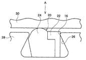
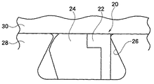
図4に示したように、この特許文献1の複合シール部材20は、例えば、耐プラズマ性、耐腐食ガス性を備えた第1のシール部材22と、シール性を備えた第2のシール部材24とから構成されている。
このような複合シール部材20は、接着剤により一体化された状態で、例えば、あり溝26を形成した第1締結部材28と、この第1締結部材28に締め付けられる第2締結部材30との間に装着される。
As shown in FIG. 4, the
Such a
ところで、特許文献1に記載されている複合シール部材20においては、図5に示したように、第1締結部材28と第2締結部材30との間が締め付けられると、第1のシール部材22と第2のシール部材24との両部材が並んだ状態で圧接される。
この状態が高温・高圧下で長時間続けられると、第1のシール部材22と第2のシール部材24とが第2の部材30に固着して剥がれなくなってしまう。
結果として、第2締結部材30を第1締結部材28から引き離す必要があったときに、それを行うことができなくなる場合があった。
By the way, in the
If this state continues for a long time under high temperature and high pressure, the
As a result, when the second fastening
本発明は、このような実状に鑑み、真空シール性能、耐プラズマ性、ならびに耐腐食ガス性などの性能を併せ持つ複合シール部材が、第1締結部材と第2締結部材の間で高温・高圧下で長時間使用されたとしても、第1締結部材と第2締結部材との間を容易に引き離すことができる複合シール部材を提供することを目的とする。 In view of such a situation, the present invention provides a composite seal member having performances such as vacuum seal performance, plasma resistance, and corrosion gas resistance, at a high temperature and high pressure between the first fastening member and the second fastening member. Even if it is used for a long time, it aims at providing the composite sealing member which can pull apart easily between a 1st fastening member and a 2nd fastening member.
上記目的を達成するための本発明は、
片あり溝2のシール溝底面2a側に配置される第1のシール部材6と、前記片あり溝2の開口端面側に配置される第2のシール部材8とが、凹凸嵌合部10で着脱自在に一体化されるとともに、前記凹凸嵌合部10が前記シール溝底面2aと略平行な面に構成されていることを特徴としている。
To achieve the above object, the present invention provides:
The
このように構成によれば、第1のシール部材6と第2のシール部材8との間は着脱自在であるため、この2部材からなる複合シール部材が固着してしまうことがない。したがって、第1締結部材と第2締結部材との間に介装し、高温・高圧下で長時間使用したとしても、第1締結部材を第2締結部材から引き離そうとすれば、容易に引き離すことができる。
According to this configuration, since the
さらに、本発明では、前記片あり溝2の傾斜した径内方側壁面2bに当接する前記第2のシール部材8の内壁面8aは、前記片あり溝2の径内方側壁面2bの傾斜角度αに対応する傾斜角度αで傾斜していることが好ましい。
このような角度で傾斜していれば、複合シール部材の初期装着性が良好である。
Furthermore, in the present invention, the
If it is inclined at such an angle, the initial mounting property of the composite seal member is good.
本発明に係る複合シール部材によれば、第1のシール部材と第2のシール部材との係合が容易に解除される。したがって、高温・高圧で長時間使用されたとしても、この複合シール部材が装着された第1締結部材と第2締結部材との間を容易に引き離すことができる。 According to the composite seal member of the present invention, the engagement between the first seal member and the second seal member is easily released. Therefore, even if the composite seal member is used for a long time at high temperature and high pressure, the first fastening member and the second fastening member to which the composite seal member is attached can be easily separated.
以下、本発明に係る複合シール部材について図面を参照しながら詳細に説明する。 Hereinafter, the composite seal member according to the present invention will be described in detail with reference to the drawings.
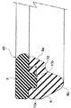
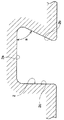
図1は、本発明の一実施例に係る複合シール部材40の片断面を示したもので、図2は、図1の複合シール部材40が装着される片あり溝2の片断面図である。
FIG. 1 shows a single cross section of a
この片あり溝2は、例えば、ドライエッチング装置やプラズマCVD装置などの半導体製造装置の継手部分に形成されたもので、そのシール溝底面2a側の幅が、片あり溝2の開口部側の幅より広くなっている。また、片あり溝2の径内方側壁面2bは傾斜面とされ、片あり溝2の径外方側壁面は垂直面2cとされている。なお、径内方側壁面2bのシール溝底面2aに対する傾斜角度はαである。
The one-sided groove 2 is formed, for example, in a joint portion of a semiconductor manufacturing apparatus such as a dry etching apparatus or a plasma CVD apparatus, and the width on the bottom side of the
図1に示した複合シール部材40は、第1のシール部材6が片あり溝2のシール溝底面2a側に、第2のシール部材8が開口端面側に装着される。すなわち、複合シール部材40は、図1の姿勢で、図2の片あり溝2内に装着される。
複合シール部材40の第1のシール部材6は、例えば、合成樹脂により形成されたもので、シール溝底面2aに接する面は平坦に形成され、第2のシール部材8に接する面には、凹凸嵌合部10の一方をなす凸部10aが形成されている。この凸部10aは、第1のシール部材6の全周に渡って環状に形成されていても良いが、所定間隔置きに突起のように形成されていても良い。
一方、上記第2のシール部材8は、断面略三角形状に形成されたもので、第1のシール部材6に接する面すなわちシール溝底面2aと略平行な面には、凹凸嵌合部10の他方を構成する凹部10bが形成されている。
第2のシール部材8の凹部10bは、第1のシール部材6の凸部10aに対応するもので、凸部10aが環状であれば凹部10bも環状に、凸部10aが所定間隔置きに形成されていれば凹部10bも所定間隔置きに形成される。なお、第1のシール部材6に凹部10bを、第2のシール部材8に凸部10aを形成しても良い。また、これら凹部10bと凸部10aとからなる凹凸嵌合部10は、互いに組み付ければ隙間なく組み付けられるが
、離反する方向に引っ張れば、組み付けを容易に解除することができる。
すなわち、本実施例の複合シール部材40では、第1のシール部材6と第2のシール部材8とは、その嵌合は着脱自在とされる。
In the
The
On the other hand, the
The
That is, in the
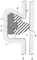
第2のシール部材8の図1における下面側先端部8bは、略円弧状に形成されている。そして、図3に示したように、複合シール部材40では、圧縮された場合に、第2のシール部材8の下面側先端部8bのみが、第2締結部材30に当接する。
第2のシール部材8の内壁面8aは、片あり溝2の径内方側壁面2bの傾斜角度αと同じ角度で傾斜している。すなわち、内壁面8aの傾斜角度αは、片あり溝2の傾斜角度αと同じ角度である。このように、第2のシール部材8に片あり溝2の傾斜角度αと等しい傾斜角度αを設けることにより、複合シール部材40の第1締結部材28に対する初期装着性が良好にされている。
The
The
上記第2のシール部材8は、弾性部材であるゴムから構成されているのが望ましい。ゴムとしては、天然ゴム、合成ゴムのいずれも使用可能である。
このような材質からなる第2のシール部材8は、複合シール部材40が圧縮された際に、第1のシール部材6からの反力が加わって、第2のシール部材8の下面側先端部8bが第2締結部材30により圧接され、これにより高いシール性を付与することができる。また、第2のシール部材8を構成するゴムは、フッ素ゴムから構成されているのがさらに望ましい。
The
When the
フッ素ゴムとしては、フッ化ビニリデン/ヘキサフルオロプロピレン系共重合体、フッ化ビニリデン/トリフルオロクロロエチレン系共重合体、フッ化ビニリデン/ペンタフルオロプロピレン系共重合体等の2元系のフッ化ビニリデン系ゴム、フッ化ビニリデン/テトラフルオロエチレン/ヘキサフルオロプロピレン系共重合体、フッ化ビニリデン/テトラフルオロエチレン/パーフルオロアルキルビニルエーテル系共重合体、フッ化ビニリデン/テトラフルオロエチレン/プロピレン系共重合体等の3元系のフッ化ビニリデンゴムやテトラフルオロエチレン/プロピレン系共重合体、テトラフルオロエチレンlパーフルオロアルキルビニルエーテル系共重合体、熱可塑性フッ素ゴムなどが使用可能である。 Fluoro rubber includes binary vinylidene fluoride such as vinylidene fluoride / hexafluoropropylene copolymer, vinylidene fluoride / trifluorochloroethylene copolymer, and vinylidene fluoride / pentafluoropropylene copolymer. Rubber, vinylidene fluoride / tetrafluoroethylene / hexafluoropropylene copolymer, vinylidene fluoride / tetrafluoroethylene / perfluoroalkyl vinyl ether copolymer, vinylidene fluoride / tetrafluoroethylene / propylene copolymer, etc. These ternary vinylidene fluoride rubbers, tetrafluoroethylene / propylene copolymers, tetrafluoroethylene perfluoroalkyl vinyl ether copolymers, thermoplastic fluororubbers, and the like can be used.
このように第2のシール部材8を構成するゴムが、フッ素ゴムから構成されていれば、第2のシール部材8が腐食性ガス、プラズマに接触したとしても、腐食性ガス、プラズマなどへの耐久性が良く、シール性が低下することがない。
Thus, if the rubber which comprises the
第1のシール部材6は、前記第2のシール部材8より硬質の合成樹脂から構成されているのが望ましく、好ましくは、フッ素樹脂、ポリイミド樹脂、ポリアミドイミド樹脂、ポリエーテルイミド樹脂、ポリアミドイミド樹脂、ポリフェニレンサルファイド樹脂、ポリベンゾイミダゾール樹脂、ポリエーテルケトン樹脂から選択した1種以上の合成樹脂から構成するのが望ましい。
The
このように第1のシール部材6が硬質の材料で形成されていれば、圧縮された際に第2のシール部材8に適宜な反力を加えることができる。
As described above, if the
この場合、フッ素樹脂としては、ポリテトラフルオロエチレン(PTFE)樹脂、テトラフルオロエチレン−パーフルオロアルキルビニルエーテル共重合体(PFA)樹脂、テトラフルオロエチレン−ヘキサフルオロプロピレン共重合体(FEP)樹脂、テトラフルオロエチレン−エチレン共重合体(ETFE)樹脂、ポリビニリデンフルオライト(PVDF)樹脂、ポリクロロトリフルオロエチレン(PCTFE)樹脂、クロロトリフルオロエチレン−エチレン共重合体(ECTFE)樹脂、ポリビニルフルオライド(PVF)樹脂などを挙げることができ、この中では、耐熱性、耐腐食性ガス、耐プラズマ性などを考
慮すれば、PTFEが好ましい。
In this case, the fluororesin includes polytetrafluoroethylene (PTFE) resin, tetrafluoroethylene-perfluoroalkyl vinyl ether copolymer (PFA) resin, tetrafluoroethylene-hexafluoropropylene copolymer (FEP) resin, tetrafluoro Ethylene-ethylene copolymer (ETFE) resin, polyvinylidene fluoride (PVDF) resin, polychlorotrifluoroethylene (PCTFE) resin, chlorotrifluoroethylene-ethylene copolymer (ECTFE) resin, polyvinyl fluoride (PVF) Among them, PTFE is preferable in view of heat resistance, corrosion resistance gas, plasma resistance, and the like.
本実施例の複合シール部材40は、上記のように構成されているが、以下にその作用について説明する。
今、第1のシール部材6と第2のシール部材8とからなる複合シール部材40は、凹凸嵌合部10のみで嵌合されている。よって、互いに離反する方向に引っ張れば、容易に解除することができる。
また、片あり溝2の傾斜角度αと第2のシール部材8との傾斜角度αが同一であるため、複合シール部材40の片あり溝2に対する装着性は良好である。
複合シール部材40を装着した状態で第1締結部材28と第2締結部材30との間を締め付けると、第2のシール部材8の下面側先端部8bが第2締結部材30に当接し、ここにシール機能が発揮される。このとき、第1のシール部材6からは、第2のシール部材8側に反力が伝達される。
このような複合シール部材40が、高温・高圧下で長時間使用されているとする。この状態から第1締結部材28と第2締結部材30とを取り外す必要がある場合には、ボルトなどの締結手段を解除し、第2締結部材30を第1締結部材28から引き離す。このとき、第1締結部材28と第2締結部材30との間は、複合シール部材40により気密が保持されている。一方、第1のシール部材6と第2のシール部材8との間は、単に凹凸嵌合部10のみでの嵌合であるため、引き離す方向への力が加われば、その嵌合は速やかに解除される。よって、第1締結部材28と第2締結部材30とを引き離すことができる。
以上、本発明の一実施例について説明したが、本発明は上記実施例に何ら限定されない。
例えば、上記実施例では、凹凸嵌合部10の形状は、上記実施例に限定されず、断面三角形状などであっても良い。また、第1のシール部材6および第2のシール部材8の材質も限定されるものではない。
The
Now, the
Moreover, since the inclination angle α of the grooved groove 2 and the inclination angle α of the
When the space between the
It is assumed that such a
As mentioned above, although one Example of this invention was described, this invention is not limited to the said Example at all.
For example, in the said Example, the shape of the uneven | corrugated
2 片あり溝
2a シール溝底面
2b 径内方側壁面
6 第1のシール部材
8 第2のシール部材
8a 内壁面
10 凹凸嵌合部
28 第1締結部材
30 第2締結部材
α 傾斜角度
2
Claims (2)
Priority Applications (1)
| Application Number | Priority Date | Filing Date | Title |
|---|---|---|---|
| JP2008228560A JP5204595B2 (en) | 2008-09-05 | 2008-09-05 | Composite seal member |
Applications Claiming Priority (1)
| Application Number | Priority Date | Filing Date | Title |
|---|---|---|---|
| JP2008228560A JP5204595B2 (en) | 2008-09-05 | 2008-09-05 | Composite seal member |
Publications (2)
| Publication Number | Publication Date |
|---|---|
| JP2010060107A true JP2010060107A (en) | 2010-03-18 |
| JP5204595B2 JP5204595B2 (en) | 2013-06-05 |
Family
ID=42187121
Family Applications (1)
| Application Number | Title | Priority Date | Filing Date |
|---|---|---|---|
| JP2008228560A Active JP5204595B2 (en) | 2008-09-05 | 2008-09-05 | Composite seal member |
Country Status (1)
| Country | Link |
|---|---|
| JP (1) | JP5204595B2 (en) |
Cited By (3)
| Publication number | Priority date | Publication date | Assignee | Title |
|---|---|---|---|---|
| WO2018146817A1 (en) * | 2017-02-13 | 2018-08-16 | 堺ディスプレイプロダクト株式会社 | Vacuum device |
| JP2019060367A (en) * | 2017-09-25 | 2019-04-18 | 三菱電線工業株式会社 | Hermetically sealed structure |
| WO2022185915A1 (en) * | 2021-03-01 | 2022-09-09 | 株式会社バルカー | Sealing structure and sealing member |
Citations (2)
| Publication number | Priority date | Publication date | Assignee | Title |
|---|---|---|---|---|
| JP2006071025A (en) * | 2004-09-02 | 2006-03-16 | Mitsubishi Cable Ind Ltd | Sealing material |
| JP2007321922A (en) * | 2006-06-02 | 2007-12-13 | Nok Corp | Seal ring |
-
2008
- 2008-09-05 JP JP2008228560A patent/JP5204595B2/en active Active
Patent Citations (2)
| Publication number | Priority date | Publication date | Assignee | Title |
|---|---|---|---|---|
| JP2006071025A (en) * | 2004-09-02 | 2006-03-16 | Mitsubishi Cable Ind Ltd | Sealing material |
| JP2007321922A (en) * | 2006-06-02 | 2007-12-13 | Nok Corp | Seal ring |
Cited By (4)
| Publication number | Priority date | Publication date | Assignee | Title |
|---|---|---|---|---|
| WO2018146817A1 (en) * | 2017-02-13 | 2018-08-16 | 堺ディスプレイプロダクト株式会社 | Vacuum device |
| JP2019060367A (en) * | 2017-09-25 | 2019-04-18 | 三菱電線工業株式会社 | Hermetically sealed structure |
| WO2022185915A1 (en) * | 2021-03-01 | 2022-09-09 | 株式会社バルカー | Sealing structure and sealing member |
| JP7436411B2 (en) | 2021-03-01 | 2024-02-21 | 株式会社バルカー | Seal structure |
Also Published As
| Publication number | Publication date |
|---|---|
| JP5204595B2 (en) | 2013-06-05 |
Similar Documents
| Publication | Publication Date | Title |
|---|---|---|
| JP5126999B2 (en) | Sealing material | |
| JP4754621B2 (en) | Composite sealing material | |
| CN110234914B (en) | Composite sealing element | |
| ES2432741T3 (en) | Pipe coupling | |
| JP5126995B2 (en) | Composite sealing material | |
| JP5204595B2 (en) | Composite seal member | |
| KR102156022B1 (en) | Tube connector assembly | |
| JP5777315B2 (en) | Composite sealing material | |
| WO2022185915A1 (en) | Sealing structure and sealing member | |
| JP5973781B2 (en) | Corrosion-resistant composite seal structure | |
| JP7068464B2 (en) | Composite sealing material | |
| JP2009174627A (en) | Composite sealant | |
| JP6613133B2 (en) | Seal structure | |
| JP2012137103A (en) | Composite seal material | |
| JP2007224944A (en) | Composite seal | |
| JP2011196505A (en) | Sliding seal | |
| GB2523066A (en) | Seal ring assembly |
Legal Events
| Date | Code | Title | Description |
|---|---|---|---|
| A621 | Written request for application examination |
Free format text: JAPANESE INTERMEDIATE CODE: A621 Effective date: 20110824 |
|
| RD02 | Notification of acceptance of power of attorney |
Free format text: JAPANESE INTERMEDIATE CODE: A7422 Effective date: 20110824 |
|
| A977 | Report on retrieval |
Free format text: JAPANESE INTERMEDIATE CODE: A971007 Effective date: 20120829 |
|
| A131 | Notification of reasons for refusal |
Free format text: JAPANESE INTERMEDIATE CODE: A131 Effective date: 20120904 |
|
| A521 | Request for written amendment filed |
Free format text: JAPANESE INTERMEDIATE CODE: A523 Effective date: 20120913 |
|
| A131 | Notification of reasons for refusal |
Free format text: JAPANESE INTERMEDIATE CODE: A131 Effective date: 20121218 |
|
| A521 | Request for written amendment filed |
Free format text: JAPANESE INTERMEDIATE CODE: A523 Effective date: 20121228 |
|
| TRDD | Decision of grant or rejection written | ||
| A01 | Written decision to grant a patent or to grant a registration (utility model) |
Free format text: JAPANESE INTERMEDIATE CODE: A01 Effective date: 20130129 |
|
| A61 | First payment of annual fees (during grant procedure) |
Free format text: JAPANESE INTERMEDIATE CODE: A61 Effective date: 20130215 |
|
| R150 | Certificate of patent or registration of utility model |
Ref document number: 5204595 Country of ref document: JP Free format text: JAPANESE INTERMEDIATE CODE: R150 Free format text: JAPANESE INTERMEDIATE CODE: R150 |
|
| FPAY | Renewal fee payment (event date is renewal date of database) |
Free format text: PAYMENT UNTIL: 20160222 Year of fee payment: 3 |
|
| R250 | Receipt of annual fees |
Free format text: JAPANESE INTERMEDIATE CODE: R250 |
|
| R250 | Receipt of annual fees |
Free format text: JAPANESE INTERMEDIATE CODE: R250 |
|
| R250 | Receipt of annual fees |
Free format text: JAPANESE INTERMEDIATE CODE: R250 |
|
| R250 | Receipt of annual fees |
Free format text: JAPANESE INTERMEDIATE CODE: R250 |
|
| S533 | Written request for registration of change of name |
Free format text: JAPANESE INTERMEDIATE CODE: R313533 |
|
| R350 | Written notification of registration of transfer |
Free format text: JAPANESE INTERMEDIATE CODE: R350 |
|
| R250 | Receipt of annual fees |
Free format text: JAPANESE INTERMEDIATE CODE: R250 |
|
| R250 | Receipt of annual fees |
Free format text: JAPANESE INTERMEDIATE CODE: R250 |
|
| R250 | Receipt of annual fees |
Free format text: JAPANESE INTERMEDIATE CODE: R250 |
|
| R250 | Receipt of annual fees |
Free format text: JAPANESE INTERMEDIATE CODE: R250 |
|
| R250 | Receipt of annual fees |
Free format text: JAPANESE INTERMEDIATE CODE: R250 |