JP2010059965A - Method for operating longitudinally scavenged two-stroke large diesel engine - Google Patents
Method for operating longitudinally scavenged two-stroke large diesel engine Download PDFInfo
- Publication number
- JP2010059965A JP2010059965A JP2009188209A JP2009188209A JP2010059965A JP 2010059965 A JP2010059965 A JP 2010059965A JP 2009188209 A JP2009188209 A JP 2009188209A JP 2009188209 A JP2009188209 A JP 2009188209A JP 2010059965 A JP2010059965 A JP 2010059965A
- Authority
- JP
- Japan
- Prior art keywords
- engine output
- scavenging
- pressure
- scavenging pressure
- engine
- Prior art date
- Legal status (The legal status is an assumption and is not a legal conclusion. Google has not performed a legal analysis and makes no representation as to the accuracy of the status listed.)
- Granted
Links
- 238000000034 method Methods 0.000 title claims abstract description 38
- 230000002000 scavenging effect Effects 0.000 claims abstract description 83
- 239000007789 gas Substances 0.000 claims abstract description 42
- 239000000446 fuel Substances 0.000 claims abstract description 21
- 239000000567 combustion gas Substances 0.000 claims abstract description 10
- 238000002485 combustion reaction Methods 0.000 claims description 26
- 230000007423 decrease Effects 0.000 claims description 14
- 230000009467 reduction Effects 0.000 claims description 4
- 238000011017 operating method Methods 0.000 claims description 3
- 230000004044 response Effects 0.000 abstract description 3
- 239000003570 air Substances 0.000 description 34
- 230000008859 change Effects 0.000 description 6
- MWUXSHHQAYIFBG-UHFFFAOYSA-N nitrogen oxide Inorganic materials O=[N] MWUXSHHQAYIFBG-UHFFFAOYSA-N 0.000 description 6
- 230000008569 process Effects 0.000 description 6
- 230000006835 compression Effects 0.000 description 3
- 238000007906 compression Methods 0.000 description 3
- XLYOFNOQVPJJNP-UHFFFAOYSA-N water Substances O XLYOFNOQVPJJNP-UHFFFAOYSA-N 0.000 description 3
- 239000002283 diesel fuel Substances 0.000 description 2
- 239000012080 ambient air Substances 0.000 description 1
- 230000001010 compromised effect Effects 0.000 description 1
- 230000001419 dependent effect Effects 0.000 description 1
- 230000001771 impaired effect Effects 0.000 description 1
- 238000002347 injection Methods 0.000 description 1
- 239000007924 injection Substances 0.000 description 1
- 239000007788 liquid Substances 0.000 description 1
- 238000011144 upstream manufacturing Methods 0.000 description 1
Images


Classifications
-
- F—MECHANICAL ENGINEERING; LIGHTING; HEATING; WEAPONS; BLASTING
- F02—COMBUSTION ENGINES; HOT-GAS OR COMBUSTION-PRODUCT ENGINE PLANTS
- F02D—CONTROLLING COMBUSTION ENGINES
- F02D23/00—Controlling engines characterised by their being supercharged
- F02D23/02—Controlling engines characterised by their being supercharged the engines being of fuel-injection type
-
- F—MECHANICAL ENGINEERING; LIGHTING; HEATING; WEAPONS; BLASTING
- F02—COMBUSTION ENGINES; HOT-GAS OR COMBUSTION-PRODUCT ENGINE PLANTS
- F02B—INTERNAL-COMBUSTION PISTON ENGINES; COMBUSTION ENGINES IN GENERAL
- F02B25/00—Engines characterised by using fresh charge for scavenging cylinders
- F02B25/02—Engines characterised by using fresh charge for scavenging cylinders using unidirectional scavenging
- F02B25/04—Engines having ports both in cylinder head and in cylinder wall near bottom of piston stroke
-
- F—MECHANICAL ENGINEERING; LIGHTING; HEATING; WEAPONS; BLASTING
- F02—COMBUSTION ENGINES; HOT-GAS OR COMBUSTION-PRODUCT ENGINE PLANTS
- F02B—INTERNAL-COMBUSTION PISTON ENGINES; COMBUSTION ENGINES IN GENERAL
- F02B33/00—Engines characterised by provision of pumps for charging or scavenging
- F02B33/32—Engines with pumps other than of reciprocating-piston type
- F02B33/34—Engines with pumps other than of reciprocating-piston type with rotary pumps
- F02B33/40—Engines with pumps other than of reciprocating-piston type with rotary pumps of non-positive-displacement type
-
- F—MECHANICAL ENGINEERING; LIGHTING; HEATING; WEAPONS; BLASTING
- F02—COMBUSTION ENGINES; HOT-GAS OR COMBUSTION-PRODUCT ENGINE PLANTS
- F02B—INTERNAL-COMBUSTION PISTON ENGINES; COMBUSTION ENGINES IN GENERAL
- F02B37/00—Engines characterised by provision of pumps driven at least for part of the time by exhaust
- F02B37/12—Control of the pumps
- F02B37/16—Control of the pumps by bypassing charging air
-
- F—MECHANICAL ENGINEERING; LIGHTING; HEATING; WEAPONS; BLASTING
- F02—COMBUSTION ENGINES; HOT-GAS OR COMBUSTION-PRODUCT ENGINE PLANTS
- F02B—INTERNAL-COMBUSTION PISTON ENGINES; COMBUSTION ENGINES IN GENERAL
- F02B37/00—Engines characterised by provision of pumps driven at least for part of the time by exhaust
- F02B37/12—Control of the pumps
- F02B37/18—Control of the pumps by bypassing exhaust from the inlet to the outlet of turbine or to the atmosphere
-
- F—MECHANICAL ENGINEERING; LIGHTING; HEATING; WEAPONS; BLASTING
- F02—COMBUSTION ENGINES; HOT-GAS OR COMBUSTION-PRODUCT ENGINE PLANTS
- F02D—CONTROLLING COMBUSTION ENGINES
- F02D23/00—Controlling engines characterised by their being supercharged
-
- F—MECHANICAL ENGINEERING; LIGHTING; HEATING; WEAPONS; BLASTING
- F02—COMBUSTION ENGINES; HOT-GAS OR COMBUSTION-PRODUCT ENGINE PLANTS
- F02D—CONTROLLING COMBUSTION ENGINES
- F02D41/00—Electrical control of supply of combustible mixture or its constituents
- F02D41/0002—Controlling intake air
- F02D41/0007—Controlling intake air for control of turbo-charged or super-charged engines
-
- F—MECHANICAL ENGINEERING; LIGHTING; HEATING; WEAPONS; BLASTING
- F02—COMBUSTION ENGINES; HOT-GAS OR COMBUSTION-PRODUCT ENGINE PLANTS
- F02D—CONTROLLING COMBUSTION ENGINES
- F02D41/00—Electrical control of supply of combustible mixture or its constituents
- F02D41/02—Circuit arrangements for generating control signals
- F02D41/04—Introducing corrections for particular operating conditions
-
- F—MECHANICAL ENGINEERING; LIGHTING; HEATING; WEAPONS; BLASTING
- F01—MACHINES OR ENGINES IN GENERAL; ENGINE PLANTS IN GENERAL; STEAM ENGINES
- F01N—GAS-FLOW SILENCERS OR EXHAUST APPARATUS FOR MACHINES OR ENGINES IN GENERAL; GAS-FLOW SILENCERS OR EXHAUST APPARATUS FOR INTERNAL COMBUSTION ENGINES
- F01N2590/00—Exhaust or silencing apparatus adapted to particular use, e.g. for military applications, airplanes, submarines
- F01N2590/02—Exhaust or silencing apparatus adapted to particular use, e.g. for military applications, airplanes, submarines for marine vessels or naval applications
-
- F—MECHANICAL ENGINEERING; LIGHTING; HEATING; WEAPONS; BLASTING
- F02—COMBUSTION ENGINES; HOT-GAS OR COMBUSTION-PRODUCT ENGINE PLANTS
- F02B—INTERNAL-COMBUSTION PISTON ENGINES; COMBUSTION ENGINES IN GENERAL
- F02B75/00—Other engines
- F02B75/02—Engines characterised by their cycles, e.g. six-stroke
- F02B2075/022—Engines characterised by their cycles, e.g. six-stroke having less than six strokes per cycle
- F02B2075/025—Engines characterised by their cycles, e.g. six-stroke having less than six strokes per cycle two
-
- F—MECHANICAL ENGINEERING; LIGHTING; HEATING; WEAPONS; BLASTING
- F02—COMBUSTION ENGINES; HOT-GAS OR COMBUSTION-PRODUCT ENGINE PLANTS
- F02B—INTERNAL-COMBUSTION PISTON ENGINES; COMBUSTION ENGINES IN GENERAL
- F02B2275/00—Other engines, components or details, not provided for in other groups of this subclass
- F02B2275/14—Direct injection into combustion chamber
-
- F—MECHANICAL ENGINEERING; LIGHTING; HEATING; WEAPONS; BLASTING
- F02—COMBUSTION ENGINES; HOT-GAS OR COMBUSTION-PRODUCT ENGINE PLANTS
- F02B—INTERNAL-COMBUSTION PISTON ENGINES; COMBUSTION ENGINES IN GENERAL
- F02B29/00—Engines characterised by provision for charging or scavenging not provided for in groups F02B25/00, F02B27/00 or F02B33/00 - F02B39/00; Details thereof
- F02B29/04—Cooling of air intake supply
- F02B29/0406—Layout of the intake air cooling or coolant circuit
-
- F—MECHANICAL ENGINEERING; LIGHTING; HEATING; WEAPONS; BLASTING
- F02—COMBUSTION ENGINES; HOT-GAS OR COMBUSTION-PRODUCT ENGINE PLANTS
- F02B—INTERNAL-COMBUSTION PISTON ENGINES; COMBUSTION ENGINES IN GENERAL
- F02B29/00—Engines characterised by provision for charging or scavenging not provided for in groups F02B25/00, F02B27/00 or F02B33/00 - F02B39/00; Details thereof
- F02B29/04—Cooling of air intake supply
- F02B29/045—Constructional details of the heat exchangers, e.g. pipes, plates, ribs, insulation, materials, or manufacturing and assembly
- F02B29/0468—Water separation or drainage means
-
- F—MECHANICAL ENGINEERING; LIGHTING; HEATING; WEAPONS; BLASTING
- F02—COMBUSTION ENGINES; HOT-GAS OR COMBUSTION-PRODUCT ENGINE PLANTS
- F02B—INTERNAL-COMBUSTION PISTON ENGINES; COMBUSTION ENGINES IN GENERAL
- F02B3/00—Engines characterised by air compression and subsequent fuel addition
- F02B3/06—Engines characterised by air compression and subsequent fuel addition with compression ignition
-
- F—MECHANICAL ENGINEERING; LIGHTING; HEATING; WEAPONS; BLASTING
- F02—COMBUSTION ENGINES; HOT-GAS OR COMBUSTION-PRODUCT ENGINE PLANTS
- F02B—INTERNAL-COMBUSTION PISTON ENGINES; COMBUSTION ENGINES IN GENERAL
- F02B61/00—Adaptations of engines for driving vehicles or for driving propellers; Combinations of engines with gearing
- F02B61/04—Adaptations of engines for driving vehicles or for driving propellers; Combinations of engines with gearing for driving propellers
-
- F—MECHANICAL ENGINEERING; LIGHTING; HEATING; WEAPONS; BLASTING
- F02—COMBUSTION ENGINES; HOT-GAS OR COMBUSTION-PRODUCT ENGINE PLANTS
- F02D—CONTROLLING COMBUSTION ENGINES
- F02D2250/00—Engine control related to specific problems or objectives
- F02D2250/18—Control of the engine output torque
- F02D2250/26—Control of the engine output torque by applying a torque limit
-
- F—MECHANICAL ENGINEERING; LIGHTING; HEATING; WEAPONS; BLASTING
- F02—COMBUSTION ENGINES; HOT-GAS OR COMBUSTION-PRODUCT ENGINE PLANTS
- F02D—CONTROLLING COMBUSTION ENGINES
- F02D2400/00—Control systems adapted for specific engine types; Special features of engine control systems not otherwise provided for; Power supply, connectors or cabling for engine control systems
- F02D2400/04—Two-stroke combustion engines with electronic control
-
- Y—GENERAL TAGGING OF NEW TECHNOLOGICAL DEVELOPMENTS; GENERAL TAGGING OF CROSS-SECTIONAL TECHNOLOGIES SPANNING OVER SEVERAL SECTIONS OF THE IPC; TECHNICAL SUBJECTS COVERED BY FORMER USPC CROSS-REFERENCE ART COLLECTIONS [XRACs] AND DIGESTS
- Y02—TECHNOLOGIES OR APPLICATIONS FOR MITIGATION OR ADAPTATION AGAINST CLIMATE CHANGE
- Y02T—CLIMATE CHANGE MITIGATION TECHNOLOGIES RELATED TO TRANSPORTATION
- Y02T10/00—Road transport of goods or passengers
- Y02T10/10—Internal combustion engine [ICE] based vehicles
- Y02T10/12—Improving ICE efficiencies
Abstract
Description
本発明は、請求項1の導入部分による、長手方向に掃気される2ストロークの大型ディーゼル・エンジンの動作方法に関するものである。
The invention relates to a method of operating a two-stroke large diesel engine that is scavenged in the longitudinal direction according to the introductory part of
例えば、船舶又は電気エネルギ生成のための据え付け型の装置に使用される2ストロークの大型ディーゼル・エンジンなどの往復ピストン燃焼エンジンの性能を向上させるために、排気ガス・ターボ・チャージャによって、燃焼サイクルに従って、上昇した圧力の下で、外気がシリンダの燃焼空間に導入される。ここで、シリンダの燃焼空間の燃焼プロセスからの高温の排気ガスが、出口弁を開くことにより、給気グループに供給され、排気ガスの熱エネルギの一部を利用することができる。給気グループは、本質的にタービンを含み、タービンは、給気グループに入る圧縮された高温の排気ガスによって駆動される。次に、タービンがコンプレッサを駆動し、それにより、外気が吸引され圧縮される。タービンを備えたコンプレッサは、ターボ・チャージャ又は排気ガス・ターボ・チャージャと称されるが、その下流に、いわゆるディフューザ、給気冷却器、水分離器及び入口レシーバが配置される。圧縮された外気は、給気又は掃気として知られているが、そこから最終的に大型ディーゼル・エンジンのシリンダの個々の燃焼空間に供給される。したがって、給気グループの使用によって、外気の供給を増加することができ、シリンダの燃焼空間の燃焼プロセスの効率を向上させることができる。 For example, to improve the performance of a reciprocating piston combustion engine such as a two-stroke large diesel engine used in stationary equipment for ship or electrical energy generation, according to the combustion cycle by an exhaust gas turbocharger Under the increased pressure, outside air is introduced into the combustion space of the cylinder. Here, the hot exhaust gas from the combustion process in the combustion space of the cylinder is supplied to the air supply group by opening the outlet valve, and a part of the thermal energy of the exhaust gas can be utilized. The charge group essentially comprises a turbine, which is driven by compressed hot exhaust gas entering the charge group. The turbine then drives the compressor, which draws outside air and compresses it. A compressor equipped with a turbine is called a turbocharger or an exhaust gas turbocharger, and a so-called diffuser, charge air cooler, water separator and inlet receiver are arranged downstream thereof. Compressed ambient air, known as charge or scavenging, is finally fed from there to the individual combustion spaces of the large diesel engine cylinders. Therefore, the use of the air supply group can increase the supply of outside air and improve the efficiency of the combustion process in the combustion space of the cylinder.
燃料価格が高いので、燃料節約のために、ディーゼル燃料エンジンは、とりわけ貨物船では、部分負荷で動作させることが多い。部分負荷という用語は、エンジン出力が最大エンジン出力より低いことを示す。排気ガス・ターボ・チャージャを備えた2ストロークの大型ディーゼル・エンジンの場合、掃気圧力が低いことによりシリンダの掃き出しが良くないので、一般的には最大エンジン出力の30〜50%の部分負荷では、燃料消費率は増大する。さらに、このようなディーゼル燃料エンジンを部分負荷の動作範囲で長期間動作させると、機能性を損なうおそれがある。 Due to the high fuel prices, diesel fuel engines are often operated at partial loads, especially in cargo ships, to save fuel. The term partial load indicates that the engine power is lower than the maximum engine power. In the case of a two-stroke large diesel engine equipped with an exhaust gas turbocharger, the scavenging pressure is low, so the cylinder is not well swept out. Generally, at a partial load of 30-50% of the maximum engine output, The fuel consumption rate increases. Furthermore, if such a diesel fuel engine is operated in the partial load operating range for a long time, the functionality may be impaired.
部分負荷の動作範囲での2ストロークの大型ディーゼル・エンジンの効率を改善するために、掃気圧力を、周知の方法で、可能な限りの最大値まで上昇させることができる。そのために、例えばEP−A−1956210に記載されているように、排気ガスがタービンに入る排気ガス・ターボ・チャージャの入口領域に配置されたノズルのノズル・リングの断面を、それに対応して減少させることができる。さらに、タービン形状を変更することができるターボ・チャージャを使用することにより、掃気圧力を上昇させることができる可能性もある。 In order to improve the efficiency of a two-stroke large diesel engine in the part-load operating range, the scavenging pressure can be raised to the maximum possible value in a well-known manner. To that end, as described for example in EP-A-1956210, the cross-section of the nozzle ring of the nozzle arranged in the inlet region of the exhaust gas turbocharger where the exhaust gas enters the turbine is correspondingly reduced. Can be made. Furthermore, the scavenging pressure may be increased by using a turbocharger that can change the turbine shape.
しかし、掃気圧力を可能な限りの最大値へ上昇させると、エンジン出力のより高い範囲での排気ガス・ターボ・チャージャの機能性に影響を及ぼすおそれがあり、或いは、ディーゼル・エンジンが機械的及び/又は熱的に過負荷状態になるおそれもある。 However, increasing the scavenging pressure to the maximum possible value may affect the functionality of the exhaust gas turbocharger at higher engine power ranges, or the diesel engine may be mechanical and There is also a risk of thermal overload.
ディーゼル・エンジンの低い部分負荷で掃気圧力を上昇させる方法は全て、排気ガスの窒素酸化物(NOX)の値を高めることになる。したがって、排出基準に適合するためには、ディーゼル・エンジンの他の負荷範囲でのNOXの排気を低下させなければならない。 All methods of increasing the scavenging pressure in a low partial load of the diesel engine will increase the value of the nitrogen oxides in the exhaust gas (NO X). Therefore, in order to meet emission standards must reduce the exhaust of the NO X in the other load range of the diesel engine.
本発明の目的は、ディーゼル・エンジン及び排気ガス・ターボ・チャージャの機能的な信頼性を損なわず、エンジン出力の全範囲にわたってNOXの排出を許容可能なレベルに維持し、エンジンの部分負荷の範囲でも高効率を保証する、長手方向に掃気される2ストロークの大型ディーゼル・エンジンの動作方法を提供することである。 An object of the present invention does not impair the functional reliability of the diesel engine and the exhaust gas turbocharger, and maintained at a level acceptable for discharge of the NO X over the entire range of engine output, partial load of the engine It is to provide a method of operating a two stroke large diesel engine that is scavenged in the longitudinal direction, ensuring high efficiency even in range.
本発明の目的は、請求項1の特徴を有する方法によって実現される。本発明方法の好ましい実施例は従属請求項に記載される。
The object of the invention is achieved by a method having the features of
本発明方法は、長手方向に掃気される2ストロークの大型ディーゼル・エンジンの動作に役立つ。2ストロークの大型ディーゼル・エンジンは、各シリンダの入口領域に掃気スリットを有し、予め設定された量の掃気を供給する。さらに、各シリンダはそれぞれシリンダ・カバーと、燃焼ガスを排出するための少なくとも1つの出口弁とを有する。本発明方法では、周囲圧力P0で利用可能な外気が、排気ガス・ターボ・チャージャによって摂取され、予め設定された掃気圧力PLで掃気スリットを介して掃気としてシリンダに供給され、導入された空気はシリンダで圧縮され、その空気中に液体燃料又は気体などの燃料が噴射され、続いて燃焼させられて、燃焼ガスが空気及び燃料によって生成される。本発明では、掃気圧力PLが、予め設定されたエンジン出力LSまで、エンジン出力又はディーゼル・エンジンの負荷に応じて常に上昇し、予め設定されたエンジン出力LSにおいて、0.2〜1bar(20〜100kPa)の急激な低下をし、その後は、掃気圧力PLがエンジン出力Lに応じて再度常に上昇することが重要である。予め設定されたエンジン出力LSは、より大きい出力範囲にあることが好ましく、とりわけディーゼル・エンジンの最大出力範囲の大きい方から4分の1の範囲にあることが好ましい。ここで、最大出力範囲の大きい方から4分の1の範囲は、最大エンジン出力の75〜100%のエンジン出力に関係し、最大エンジン出力はL100%とも称される。 The method of the present invention is useful for the operation of a two-stroke large diesel engine that is scavenged longitudinally. A two-stroke large diesel engine has a scavenging slit in the inlet region of each cylinder to supply a preset amount of scavenging. In addition, each cylinder has a cylinder cover and at least one outlet valve for exhausting combustion gases. In the method of the invention, outside air is available at ambient pressure P 0, is ingested by an exhaust gas turbocharger, is fed to the cylinder as scavenging via the scavenging slits at a preset scavenging air pressure P L, is introduced Air is compressed in a cylinder and fuel, such as liquid fuel or gas, is injected into the air and subsequently burned, and combustion gas is generated by the air and fuel. In the present invention, the scavenging pressure P L is, in advance until the set engine power L S, always rise depending on the load of the engine output or diesel engine, in a preset engine power L S, 0.2~1bar a sharp drop in (20~100kPa), then it is important to scavenging pressure P L always rises again in response to the engine output L. The preset engine output L S is preferably in a larger output range, and more preferably in the range from the larger of the maximum output range of the diesel engine to a quarter. Here, the range from the larger maximum output range to a quarter is related to the engine output of 75 to 100% of the maximum engine output, and the maximum engine output is also referred to as L 100% .
エンジン出力とエンジン負荷という用語は同じ用語として用いられる。以下では、給気圧力と掃気圧力という用語も同じ用語として用いられる。 The terms engine power and engine load are used as the same terms. Hereinafter, the terms supply pressure and scavenging pressure are also used as the same terms.
掃気圧力PLの急激な低下は、75〜90%のエンジン出力範囲で起きることが好ましい。とりわけ、給気圧力の急激な変化は、83〜87%のエンジン負荷で起きることが好ましい。 Sudden drop of the scavenging pressure P L is preferably occurring in the engine output range 75 to 90%. In particular, it is preferable that the rapid change in the supply air pressure occurs at an engine load of 83 to 87%.
給気圧力PLの急激な圧力低下は、0.2〜0.7bar(20〜70kPa)であることが好ましい。とりわけ、0.2〜0.6bar(20〜60kPa)であることが好ましい。 Sudden pressure drop in the supply pressure P L is preferably a 0.2~0.7bar (20~70kPa). In particular, it is preferably 0.2 to 0.6 bar (20 to 60 kPa).
さらに、給気圧力は、急激な低下の前後ではエンジン出力に従って常に上昇することが好ましく、その関係は、圧力の急な変化以外ではエンジン負荷に対して本質的に線形に上昇することが好ましい。 Further, it is preferable that the supply air pressure always increases according to the engine output before and after the rapid decrease, and the relationship preferably increases essentially linearly with respect to the engine load except for a sudden change in pressure.
給気圧力は、標準的な動作方法に対して概して高く、40%のエンジン負荷においては、1.8〜2.5bar(180〜250kPa)であることが好ましい。掃気圧力値は絶対圧力値である。外気が吸引されるときの外気圧に対する圧力差は、いずれについても、前述の値に対してそれぞれ外気圧の大きさの分だけ小さい。 The charge air pressure is generally high for standard operating methods and is preferably 1.8-2.5 bar (180-250 kPa) at 40% engine load. The scavenging pressure value is an absolute pressure value. The pressure difference with respect to the outside air pressure when the outside air is sucked is smaller than the above-mentioned values by the magnitude of the outside air pressure.
給気圧力の急激な低下が起きる予め設定されたエンジン出力LSより低いエンジン出力範囲において、本質的に線形の掃気圧力PLの上昇は、エンジン出力1%当たり0.035〜0.045bar(3.5〜4.5kPa)、とりわけエンジン出力1%当たり0.040〜0.041bar(4.0〜4.1kPa)であることが好ましい。給気圧力PLの急激な低下が起きる予め設定されたエンジン出力LSより高いエンジン出力範囲においては、エンジン出力に対する本質的に線形の給気圧力の上昇は、最大エンジン出力まで、エンジン出力1%当たり0.040〜0.045bar(4.0〜4.5kPa)、とりわけエンジン出力1%当たり0.041〜0.043bar(4.1〜4.3kPa)であることが好ましい。
In the engine power range below the preset engine power L S where a sharp drop in the charge pressure occurs, the essentially linear increase in scavenging pressure P L is between 0.035 and 0.045 bar ( 3.5 to 4.5 kPa), particularly 0.040 to 0.041 bar (4.0 to 4.1 kPa) per 1% of engine output. In an engine output range higher than a preset engine output L S where a sharp drop in the supply air pressure P L occurs, an essentially linear increase in the supply air pressure relative to the engine output will result in an
給気圧力PLの急激な低下を、1つ又は複数の連続した段階で起こすことができるが、単一の段階であることが好ましい。 The sudden drop in the supply pressure P L can occur in one or more successive stages, but is preferably a single stage.
本発明方法の好ましい実施例では、より低い範囲のエンジン出力、すなわち最大エンジン出力の0〜65%の範囲のエンジン出力において、掃気圧力PLは、標準動作モードに対して上昇した状態で動作し、この上昇は、40%のエンジン出力において約0.25bar(25kPa)であり、典型的には65%のエンジン出力において0.4bar(40kPa)である。出口弁の開放及び燃料噴射は、標準動作モードの場合とほぼ同じときに行われる。給気圧力が高いと、燃焼圧力が高くなり、したがってNOX排出も高くなるが、燃焼はより効率的になり、その結果、燃料消費率が低くなる。 In a preferred embodiment of the method of the present invention, at a lower range of engine power, i.e., engine power in the range of 0 to 65% of maximum engine power, the scavenging pressure P L operates at an elevated level relative to the standard operating mode. This increase is approximately 0.25 bar (25 kPa) at 40% engine power and typically 0.4 bar (40 kPa) at 65% engine power. The opening of the outlet valve and the fuel injection are performed at substantially the same time as in the standard operation mode. If the supply pressure is high, the combustion pressure is high, therefore it also increases NO X emissions, combustion becomes more efficient, as a result, the fuel consumption rate is lowered.
本発明方法において、標準動作モードに対して掃気圧力を上昇させることは、周知の圧力上昇手段によって実現することができる。より強力な排気ガス・ターボ・チャージャを使用することができるか、又は例えば排気ガスの流速を増加させるための開口を、例えばEP−A−1956210に記載されているように、ターボ・チャージャの上流にある排気ガス・ダクト中で使用することができる。 In the method of the present invention, raising the scavenging pressure with respect to the standard operation mode can be realized by known pressure raising means. A more powerful exhaust gas turbocharger can be used, or an opening to increase the exhaust gas flow rate, for example upstream of the turbocharger, for example as described in EP-A-1956210 It can be used in the exhaust gas duct at
65%のエンジン出力から、掃気圧力の急激な低下が行われる予め決められたエンジン出力LS、すなわち好ましくは約85%までの範囲のエンジン出力において、好ましい動作モードでは、標準動作モードに対して上昇した掃気圧力が同様に用いられ、同時に出口弁が標準プロセスより遅く閉鎖され、その結果、シリンダが燃焼プロセスに続いてより長い時間掃気され、それによりシリンダ内の圧力が次の燃焼サイクルのために低下する。それにより、燃焼は効率的ではなくなるが、燃焼温度もやはり低下して、それにより、NOX排出が減少する。したがって、出口弁の閉鎖を遅らせることにより、燃焼圧力が低下し、出口弁の閉鎖及び燃料の供給は、シリンダの燃焼圧力が標準プロセスとほぼ対応するように選択される。 From 65% engine power to a predetermined engine power L S where a sharp drop in scavenging pressure takes place, i.e. engine power preferably in the range up to about 85%, the preferred operating mode is relative to the standard operating mode. Elevated scavenging pressure is used as well, at the same time the outlet valve is closed later than the standard process, so that the cylinder is scavenged for a longer time following the combustion process, so that the pressure in the cylinder is for the next combustion cycle To drop. Thus, although combustion is not efficient, the combustion temperature decreases again, whereby NO X emissions are reduced. Accordingly, by delaying the closing of the outlet valve, the combustion pressure is reduced and the closing of the outlet valve and the fuel supply are selected such that the combustion pressure of the cylinder corresponds approximately to the standard process.
最大出力の70〜80%のエンジン出力では、出口弁は、標準動作モードに対して10〜15°遅れて閉鎖する。角度の表示はクランク角を意味する。ピストンの下死点の位置では、シリンダ、シリンダ・カバー及びピストンによって境界が定められる燃焼空間は最大容積を有し、180°のクランク角に相当し、上死点の位置では、燃焼空間の容積が最小になり、0°又は360°のクランク角と同一となる。標準プロセスの出口弁は、(ストローク/ボア比及びシリンダの圧縮比に応じて)クランク角が220〜265°の範囲で閉鎖されるので、本発明方法の前述のエンジン出力範囲での出口弁の閉鎖は、クランク角が230〜280°の範囲、好ましくは260〜280°の範囲で行われる。 At an engine power of 70-80% of maximum power, the outlet valve closes 10-15 ° later than the standard operating mode. The angle display means the crank angle. At the bottom dead center position of the piston, the combustion space delimited by the cylinder, cylinder cover and piston has a maximum volume, corresponding to a crank angle of 180 °, and at the top dead center position the volume of the combustion space. Is minimized and is the same as a crank angle of 0 ° or 360 °. The standard process outlet valve is closed (depending on the stroke / bore ratio and the cylinder compression ratio) with a crank angle in the range of 220-265 °, so that the outlet valve at the aforementioned engine power range of the method of the present invention. Closing is performed with a crank angle in the range of 230 to 280 °, preferably in the range of 260 to 280 °.
85%のエンジン出力から、100%のエンジン出力に相当する最大エンジン出力まで、すなわち掃気圧力の急激な低下が起きる所定のエンジン出力LS以降のエンジン出力範囲では、掃気圧力は、圧力の急激な低下の後に生じる低いレベルから、エンジン出力に従って再び常に上昇する。この範囲では、掃気圧力はなお、標準プロセスに対して典型的には0.1〜0.15bar(10〜15kPa)高い。 From the engine output of 85% to the maximum engine output corresponding to the engine output of 100%, that is, in the engine output range after the predetermined engine output L S in which the scavenging pressure suddenly decreases, the scavenging pressure has a sharp pressure. From the low level that occurs after the drop, it always rises again according to the engine power. In this range, the scavenging pressure is still typically 0.1 to 0.15 bar (10 to 15 kPa) higher than the standard process.
圧力の急激な低下、すなわち掃気圧力の急激な低下は、例えばそれに応じて構成され制御可能な排気ガス・ターボ・チャージャによって起こすことができるか、又は排気ガス・ターボ・チャージャのターボ・チャージャ領域を通り越すバイパス・ラインの使用によって実現することができ、その際バイパス・ラインに設けられたバルブが、好ましくは70〜90%の範囲のエンジン出力、とりわけ約85%のエンジン出力で急激に開放され、それにより排気ガスの一部、好ましくは排気ガス量の約5%が、排気ガス・ターボ・チャージャを通り越すバイパス内を通って案内され、排気管に直接導かれる。ここで、エンジン出力がさらに増大するとき、すなわち圧力の段階的な低下が引き起こされる予め決められたエンジン出力LSから最大エンジン出力までの範囲では、バイパスが開放したままである。 A sudden drop in pressure, i.e. a sharp drop in scavenging pressure, can be caused, for example, by an accordingly configured and controllable exhaust gas turbocharger or a turbocharger region of the exhaust gas turbocharger. Can be realized by the use of a bypass line that passes, in which the valve provided in the bypass line is opened rapidly, preferably with an engine power in the range of 70-90%, in particular with an engine power of about 85%, Thereby, a part of the exhaust gas, preferably about 5% of the exhaust gas amount, is guided through a bypass passing through the exhaust gas turbocharger and directly led to the exhaust pipe. Here, when the engine output further increases, that is, in the range from the predetermined engine output L S to the maximum engine output that causes a step-wise decrease in pressure, the bypass remains open.
圧力の急激な低下を実現するには、排気ガス・ターボ・チャージャの給気側領域のバイパスを使用することも可能である。ここで、予め設定されたエンジン出力LSに達すると、バルブは同様に急激に開放されて、排気ガス・ターボ・チャージャは、外気に加えて排気ガス・ターボ・チャージャの出口の圧縮された掃気も吸引し、それにより掃気圧力がそれに応じて低下する。 In order to achieve a rapid drop in pressure, it is possible to use a bypass in the supply side region of the exhaust gas turbocharger. Here, upon reaching the preset engine output L S, the valve is opened similarly rapid, exhaust gas turbo charger, compressed scavenging outlet of the exhaust gas turbocharger in addition to the outside air Are also aspirated, thereby reducing the scavenging pressure accordingly.
燃焼温度、排気ガス、NOX排出及び燃料消費率に関して、本発明方法を理想的に実行するには、2ストロークの大型ディーゼル・エンジンは、電子的に制御可能な出口弁、電子的に制御可能な燃料噴射装置及び本発明による掃気圧力を制御する装置を備えるべきである。 Combustion temperature, exhaust gas, with respect to NO X emissions and fuel consumption, to perform the method of the present invention ideally has two-stroke large diesel engine, the electronically controllable outlet valve, electronically controllable And a device for controlling the scavenging pressure according to the present invention.
本発明方法により、機能的な信頼性を損なう程度までエンジンの熱負荷を増大させることなしに、且つ大幅に構造上の変更を行う必要なしに、長手方向に掃気される2ストロークの大型ディーゼル・エンジンの効率、とりわけ部分負荷動作における効率の向上、及び全ての出力範囲にわたり窒素酸化物の排出値を所定の値へ遵守させることが可能になり、既設のエンジンを本発明方法で動作させることも、簡単な手段によって改造することもできる。 The method of the present invention allows a two-stroke large diesel engine to be scavenged longitudinally without increasing the engine heat load to the point where functional reliability is compromised and without requiring significant structural changes. It is possible to improve the efficiency of the engine, particularly in partial load operation, and to make the emission value of nitrogen oxides comply with a predetermined value over the entire output range. It can also be modified by simple means.
本発明を、以下の図面を参照して以下でさらに説明する。 The invention is further described below with reference to the following drawings.
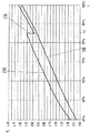
図1は、掃気圧力PLとエンジン出力Lの関係について、2ストロークの大型ディーゼル・エンジンの標準動作モードと本発明方法との比較を示す。掃気圧力PLを、単位バールで縦軸にプロットし、エンジン出力Lを横軸にプロットしている。エンジン出力を、最大エンジン出力に対するパーセント表示で示している。 FIG. 1 shows a comparison between the standard operating mode of a two-stroke large diesel engine and the method of the present invention regarding the relationship between the scavenging pressure P L and the engine output L. The scavenging pressure P L is plotted on the vertical axis in unit bar, and the engine output L is plotted on the horizontal axis. Engine power is shown as a percentage of maximum engine power.
図1では、曲線100は、長手方向に掃気される2ストロークの大型ディーゼル・エンジンの標準動作モードのエンジン出力Lに対する掃気圧力PLを示している。この曲線においては、掃気圧力PLは、エンジン出力Lに従って常に上昇し、すなわち急激な変化が起きない。その関係は線形であり、すなわち掃気圧力PLが常にエンジン出力の変化に反応し、エンジン出力の全範囲についてエンジン出力に対して比例変化する。曲線100は、直線に近い曲線を描き、その傾きはエンジン出力1%当たり0.0375bar(3.75kPa)であり、掃気圧力PL、すなわち給気圧力は、エンジン出力40%において約1.6875bar(168.75kPa)である。
In Figure 1,
図1では、曲線200は、本発明方法によるエンジン出力Lに対する掃気圧力PLを示す。この曲線においては、掃気圧力PLは、標準プロセスと比較して常に高い。本発明方法では、掃気圧力PLは、曲線100に示す標準プロセスより、エンジン出力40%において約0.25bar(25kPa)、エンジン出力80%において約0.4375bar(43.75kPa)高い。
In Figure 1, curve 200 shows the scavenging pressure P L with respect to the engine output L according to the method of the present invention. In this curve, the scavenging pressure P L is always higher as compared to the standard process. In the method of the present invention, the scavenging pressure P L is about 0.25 bar (25 kPa) at an engine output of 40% and about 0.4375 bar (43.75 kPa) at an engine output of 80% than the standard process shown in the
本発明方法の掃気圧力PLは、85%より低いエンジン出力ではエンジン出力Lに従って常に上昇し、約85%のエンジン出力において、約0.3125bar(31.25kPa)の掃気圧力の急激な低下を示し、その後、再びエンジン出力Lに従って常に上昇する。85%より高い及び低いエンジン出力では、エンジン出力に対する掃気圧力PLの関係は直線的な曲線によって示される。すなわち掃気圧力PLは、予め設定されたエンジン出力85%のエンジン出力LSにおいて圧力が急激に変化することは別にして、全てのエンジン出力範囲において、常にエンジン出力Lの変化に反応し、比例変化する。 The scavenging pressure P L of the method of the present invention always increases according to the engine power L at engine powers below 85%, with a sharp drop in scavenging pressure of about 0.3125 bar (31.25 kPa) at about 85% engine power. After that, it always rises again according to the engine output L. At higher than 85% and low engine power, the relationship of the scavenging pressure P L with respect to the engine output is indicated by a linear curve. That is, the scavenging pressure P L always reacts to the change in the engine output L in the entire engine output range, apart from the rapid change in the engine output L S of the engine output 85% set in advance. Proportionally changes.
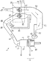
様々な構成要素の協働を概略的に示して説明するために、図2は、本発明の大型ディーゼル・エンジンの排気ガス・ターボ・チャージャ装置の原理構成を示しており、その装置は、長手方向に掃気される2ストロークの大型ディーゼル・エンジンに適用され、以下で参照番号1によってその全体は示されている。
In order to schematically show and explain the cooperation of the various components, FIG. 2 shows the principle configuration of the exhaust gas turbocharger device of a large diesel engine according to the present invention. Applies to a two-stroke large diesel engine that is scavenged in the direction, indicated in its entirety by
大型ディーゼル・エンジン1は、それ自体は周知であるが、典型的には、シリンダ・カバー5内に配置された出口弁7を有する複数のシリンダ3を含み、そのシリンダ3内では、ピストン15が、下死点UTと上死点OTとの間の走行面に沿って上下に移動可能に配置されている。シリンダ3の壁は、周知のように、シリンダ・カバー5及びピストン15と共に、シリンダ3の燃焼空間を決定する。シリンダ3の入口領域2では、掃気スリット4として構成された複数の掃気開口部4が設けられている。掃気スリット4は、ピストン15の位置に応じて、ピストンによってカバーされるか、又は開放した状態になっている。掃気10は、給気10とも呼ばれるが、掃気開口部4を通ってシリンダ3の燃焼空間に流入することができる。燃焼中に生成された燃焼ガス6は、シリンダ・カバー5内に配置された開放している出口弁7を通り、続いて排気ダクト16内を流れ、排気ガス・ターボ・チャージャ9に至る。
The
排気ガス・ターボ・チャージャ9は、外気8の圧縮のためのコンプレッサ・ホイール18を備えるコンプレッサ、並びにタービン・ホイール19を備えるタービンを含む。コンプレッサ・ホイール18は、シャフトによってタービン・ホイール19に回転式に固定して連結されているため、コンプレッサ・ホイール18はタービン・ホイール19によって駆動される。タービン及びコンプレッサは、ハウジング17内に配置され、排気ガス・ターボ・チャージャ9を形成し、その排気ガス・ターボ・チャージャ9は、ここではコンプレッサ側に形成され、遠心コンプレッサとして構成されている。タービンは、シリンダ3の燃焼空間から流入する高温の燃焼ガス6によって駆動される。
The
シリンダ3の燃焼空間を掃気10で満たすには、外気8を、コンプレッサ・ホイール18によってマニホルドを介して吸引し、排気ガス・ターボ・チャージャ9で圧縮して、最終的にシリンダ3にためる掃気圧力PLよりわずかに高い圧力にする。圧縮された外気8は、排気ガス・ターボ・チャージャ9から、下流に配置されたディフューザ20及び給気冷却器21を通り、水分離器22を介して、入口レシーバ25に掃気10として達する。入口レシーバ25から、圧縮された給気10が、掃気スリット4を通って、上昇した掃気圧力PLで最後にシリンダ3の燃焼空間に達する。
In order to fill the combustion space of the
図2に示す実施例はさらに、バイパス・ライン35を示し、そのバイパス・ライン35は、タービン側26で排気ガス・ターボ・チャージャ9を通り越す。バイパス・ラインは、バルブ30及びスロットル32を有する。バルブは、2つの位置、すなわち開又は閉の位置をとることができる。スロットルは、例えば、ノズル・リングによって形成することができ、バイパス・ラインの断面の縮小に役立つ。ここでは、断面の縮小は、一定に保たれることが好ましい。バイパス・ラインの断面は、バルブが開いている場合に、排気ダクト16に導かれる燃焼ガス6の3〜8%、好ましくは4〜6%、とりわけ約5%が、バイパス・ラインを通って案内されるように選択される。バイパス・ラインを通って案内される燃焼ガスは、排気ガス・ターボ・チャージャ9を通り越して案内され、したがって、給気10の圧縮に寄与することはできない。
The embodiment shown in FIG. 2 further shows a
図3は、本発明の大型ディーゼル・エンジン1のさらなる実施例の概略図を示す。バイパス・ライン45が、コンプレッサ側27に取り付けられ、したがって、排気ガス・ターボ・チャージャ9のコンプレッサを通り越す。バイパス・ライン45は、バルブ40及びスロットル42を有し、そのバルブ40及びスロットル42は、図2に示す実施例のバルブ30及びスロットル32と同じように形成され、同じ機能を有する。図3に示すさらなる要素の機能は、図2の対応する要素について説明したものと同じである。
FIG. 3 shows a schematic view of a further embodiment of the
バルブ40が開いている場合は、コンプレッサ・ホイール18によってバイパス・ライン45から空気が吸引され、それにより、コンプレッサの性能、したがって給気圧力もそれに対応して低下する。スロットル42は、例えば、ノズル・リングによって形成することができ、バイパス・ライン45の断面の縮小に役立つ。断面の縮小は、一定であることが好ましい。バイパス・ライン45の断面及びスロットル42は、バルブ40を開くことによって、掃気圧力が、排気ガス・ターボ・チャージャ9の出口で0.2〜1bar(20〜100kPa)、好ましくは0.2〜0.7bar(20〜70kPa)低下するように形成される。
When the
図4は、エンジン出力Lに対応する燃料消費率BVについて、2ストロークの大型ディーゼル・エンジンの標準動作モードと、本発明方法との比較を示す。g/kWhで示される燃料消費率は、BSFC値(BSFCとは、Brake Specific Fuel Consumption(正味燃料消費率)である)に対応し、これは燃料消費率(gph(グラム/時間))/エンジン出力(kW)によって計算される。エンジン出力は、w×Tqによって計算され、ここでwは回転数(rpm)であり、Tqはトルク(Nm)である。 FIG. 4 shows a comparison between the standard operation mode of a two-stroke large diesel engine and the method of the present invention for the fuel consumption rate BV corresponding to the engine output L. The fuel consumption rate indicated in g / kWh corresponds to the BSFC value (BSFC is the Bracket Specific Fuel Consumption), which is the fuel consumption rate (gph (gram / hour)) / engine Calculated by output (kW). The engine output is calculated by w × Tq, where w is the number of revolutions (rpm) and Tq is the torque (Nm).
図4では、燃料消費率BVを縦軸にプロットし、エンジン出力Lを横軸にプロットしている。エンジン出力は、最大エンジン出力のパーセント表示で示されている。 In FIG. 4, the fuel consumption rate BV is plotted on the vertical axis, and the engine output L is plotted on the horizontal axis. Engine power is shown as a percentage of maximum engine power.
図4の曲線400は、本発明方法によるエンジン出力に対する燃料消費率を示し、曲線300は、標準動作モードによる燃料消費率を示す。図4から、本発明方法の燃料消費率は、とりわけ最大エンジン出力の約75%より低い部分負荷の領域において、標準動作モードと比較して大幅に低くなることが明確に認識できる。
1 エンジン
2 入口領域
3 シリンダ
4 掃気スリット
5 シリンダ・カバー
6 燃焼ガス
7 出口弁
8 外気
9 排気ガス・ターボ・チャージャ
10 掃気
15 ピストン
16 排気ダクト
17 ハウジング
18 コンプレッサ・ホイール
19 タービン・ホイール
20 ディフューザ
21 給気冷却器
22 水分離器
25 入口レシーバ
26 タービン側
27 コンプレッサ側
30、40 バルブ
32、42 スロットル
35、45 バイパス・ライン
PL 掃気圧力、給気圧力
P0 周囲圧力
LS 予め設定されたエンジン出力
L100% 最大エンジン出力
UT 下死点
OT 上死点
DESCRIPTION OF
Claims (9)
予め設定された量の掃気を導入するために各シリンダ(3)の入口領域(2)に掃気スリット(4)を設け、燃焼ガス(6)を排出するために各シリンダ(3)のシリンダ・カバー(5)に出口弁(7)を設け、周囲圧力(P0)で利用可能な外気(8)を、排気ガス・ターボ・チャージャ(9)によって取り込み、予め設定された掃気圧力(PL)で前記掃気スリット(4)を介して掃気(10)として前記シリンダ(3)に供給し、導入された空気を前記シリンダ(3)内で圧縮し、前記空気中に燃料を噴射し、続いて燃焼させ、燃焼プロセス中に形成された前記燃焼ガス(6)を、前記排気ガス・ターボ・チャージャ(9)のタービンに排気ダクト(16)を介して供給する、動作方法において、
前記掃気圧力(PL)が、予め設定されたエンジン出力LSまで前記ディーゼル・エンジンのエンジン出力(L)に応じて連続的に上昇し、前記予め設定されたエンジン出力LSにおいて、0.2〜1barの段階的な低下をするようにし、前記段階的な低下の後、前記掃気圧力(PL)が、前記エンジン出力(L)に応じて連続的に再度上昇することを特徴とする、動作方法。 A method of operating a longitudinally scavenged two-stroke large diesel engine (1) having at least one cylinder comprising:
A scavenging slit (4) is provided in the inlet region (2) of each cylinder (3) to introduce a pre-set amount of scavenging, and the cylinders of each cylinder (3) to discharge combustion gas (6) The cover (5) is provided with an outlet valve (7), and outside air (8) available at ambient pressure (P 0 ) is taken in by the exhaust gas turbocharger (9), and a preset scavenging pressure (P L ) Is supplied to the cylinder (3) as the scavenging (10) through the scavenging slit (4), and the introduced air is compressed in the cylinder (3), and fuel is injected into the air. In the method of operation, wherein the combustion gas (6) formed during the combustion process is fed to the turbine of the exhaust gas turbocharger (9) via an exhaust duct (16),
The scavenging pressure (P L) is continuously increased according to the engine output of the diesel engine to the preset engine output L S (L), in the preset engine output L S, 0. The scavenging pressure (P L ) is continuously increased again according to the engine output (L) after the gradual decrease. , How it works.
40%の前記エンジン出力から前記掃気圧力の前記段階的な低下までの領域において、エンジン出力に対する前記掃気圧力の本質的に線形の上昇が、前記エンジン出力1%当たり0.035〜0.045bar、とりわけ前記エンジン出力1%当たり0.04〜0.041barであり、
前記掃気圧力の前記段階的な低下から前記最大エンジン出力(L100%)までにおいて、前記エンジン出力に対する前記掃気圧力の本質的に線形の上昇が、前記エンジン出力1%当たり0.040〜0.045bar、とりわけ前記エンジン出力1%当たり0.041〜0.043barであることを特徴とする、請求項4に記載された動作方法。 The scavenging pressure is 1.8-2 bar in absolute pressure at the engine output of 40%;
In the region from 40% of the engine power to the gradual decrease in the scavenging pressure, an essentially linear increase of the scavenging pressure relative to the engine output is 0.035 to 0.045 bar per 1% of the engine output, Especially 0.04-0.041 bar per 1% of the engine output,
From the gradual decrease in the scavenging pressure to the maximum engine output (L 100% ), an essentially linear increase in the scavenging pressure relative to the engine output is 0.040-0. 5. A method according to claim 4, characterized in that it is 045 bar, in particular 0.041 to 0.043 bar per 1% of the engine output.
In the range from the preset engine output L S where the gradual decrease in the scavenging pressure P L is performed to the maximum engine output, the scavenging pressure occurs after the gradual decrease in pressure. 9. The operation method according to claim 7, wherein the scavenging pressure increases continuously again according to the engine output L from the magnitude of the scavenging pressure.
Applications Claiming Priority (2)
| Application Number | Priority Date | Filing Date | Title |
|---|---|---|---|
| EP08163602 | 2008-09-03 | ||
| EP08163602.9 | 2008-09-03 |
Publications (2)
| Publication Number | Publication Date |
|---|---|
| JP2010059965A true JP2010059965A (en) | 2010-03-18 |
| JP5436972B2 JP5436972B2 (en) | 2014-03-05 |
Family
ID=40303661
Family Applications (1)
| Application Number | Title | Priority Date | Filing Date |
|---|---|---|---|
| JP2009188209A Expired - Fee Related JP5436972B2 (en) | 2008-09-03 | 2009-08-17 | How to operate a two-stroke large diesel engine scavenged longitudinally |
Country Status (7)
| Country | Link |
|---|---|
| EP (1) | EP2161427B1 (en) |
| JP (1) | JP5436972B2 (en) |
| KR (2) | KR20100027957A (en) |
| CN (1) | CN101666259B (en) |
| AT (1) | ATE503094T1 (en) |
| DE (1) | DE502009000482D1 (en) |
| DK (1) | DK2161427T3 (en) |
Cited By (1)
| Publication number | Priority date | Publication date | Assignee | Title |
|---|---|---|---|---|
| CN108869060A (en) * | 2017-05-15 | 2018-11-23 | 温特图尔汽柴油公司 | For operating the method and large-sized diesel motor of large-sized diesel motor |
Citations (3)
| Publication number | Priority date | Publication date | Assignee | Title |
|---|---|---|---|---|
| JPS61294136A (en) * | 1985-06-20 | 1986-12-24 | Mitsui Eng & Shipbuild Co Ltd | Operating method for supercharger |
| JPH09256814A (en) * | 1996-03-22 | 1997-09-30 | Mitsubishi Heavy Ind Ltd | Diesel engine plant |
| JP2008196483A (en) * | 2007-02-12 | 2008-08-28 | Waertsilae Schweiz Ag | Operating method for two-stroke and large-sized diesel engine scavenging air in longitudinal direction, and large-sized diesel engine scavenging air in longitudinal direction |
Family Cites Families (6)
| Publication number | Priority date | Publication date | Assignee | Title |
|---|---|---|---|---|
| DK105374C (en) * | 1962-01-18 | 1966-09-19 | Goetaverken Ab | Two-stroke internal combustion engine, which is equipped with both an exhaust turbine-driven purge and overload compressor and an auxiliary compressor driven by any drive source. |
| JPS63192914A (en) * | 1987-02-04 | 1988-08-10 | Godo Ozawa | Supercharger of engine |
| JP3718386B2 (en) | 1999-09-09 | 2005-11-24 | ダイハツ工業株式会社 | Two-cycle engine exhaust gas recirculation control method |
| JP2003129891A (en) * | 2001-10-23 | 2003-05-08 | Daihatsu Motor Co Ltd | 2-stroke internal combustion engine having exhaust turbo-supercharger |
| EP1380737B1 (en) * | 2002-07-09 | 2005-04-20 | Wärtsilä Schweiz AG | Method for operating a two stroke reciprocating piston internal combustion engine |
| KR20080074719A (en) * | 2007-02-08 | 2008-08-13 | 베르트질레 슈바이츠 악티엔게젤샤프트 | A method for the charging of a cylinder of a longitudinally scavenged two-stroke large diesel engine with charging air, and also a longitudinally scavenged two-stroke large diesel engine |
-
2009
- 2009-06-10 DK DK09162366.0T patent/DK2161427T3/en active
- 2009-06-10 DE DE502009000482T patent/DE502009000482D1/en active Active
- 2009-06-10 AT AT09162366T patent/ATE503094T1/en active
- 2009-06-10 EP EP09162366A patent/EP2161427B1/en not_active Not-in-force
- 2009-07-29 KR KR1020090069298A patent/KR20100027957A/en active Search and Examination
- 2009-08-17 JP JP2009188209A patent/JP5436972B2/en not_active Expired - Fee Related
- 2009-09-02 CN CN2009101717631A patent/CN101666259B/en not_active Expired - Fee Related
-
2016
- 2016-01-21 KR KR1020160007619A patent/KR101734169B1/en active IP Right Grant
Patent Citations (3)
| Publication number | Priority date | Publication date | Assignee | Title |
|---|---|---|---|---|
| JPS61294136A (en) * | 1985-06-20 | 1986-12-24 | Mitsui Eng & Shipbuild Co Ltd | Operating method for supercharger |
| JPH09256814A (en) * | 1996-03-22 | 1997-09-30 | Mitsubishi Heavy Ind Ltd | Diesel engine plant |
| JP2008196483A (en) * | 2007-02-12 | 2008-08-28 | Waertsilae Schweiz Ag | Operating method for two-stroke and large-sized diesel engine scavenging air in longitudinal direction, and large-sized diesel engine scavenging air in longitudinal direction |
Cited By (1)
| Publication number | Priority date | Publication date | Assignee | Title |
|---|---|---|---|---|
| CN108869060A (en) * | 2017-05-15 | 2018-11-23 | 温特图尔汽柴油公司 | For operating the method and large-sized diesel motor of large-sized diesel motor |
Also Published As
| Publication number | Publication date |
|---|---|
| DE502009000482D1 (en) | 2011-05-05 |
| DK2161427T3 (en) | 2011-06-20 |
| ATE503094T1 (en) | 2011-04-15 |
| CN101666259B (en) | 2013-07-24 |
| CN101666259A (en) | 2010-03-10 |
| EP2161427A1 (en) | 2010-03-10 |
| KR20160011223A (en) | 2016-01-29 |
| JP5436972B2 (en) | 2014-03-05 |
| KR101734169B1 (en) | 2017-05-11 |
| EP2161427B1 (en) | 2011-03-23 |
| KR20100027957A (en) | 2010-03-11 |
Similar Documents
| Publication | Publication Date | Title |
|---|---|---|
| US8667952B2 (en) | Method and device for controlling diesel engine with forced induction system | |
| US7934379B2 (en) | Internal combustion engine comprising an exhaust gas turbocharger | |
| JP4898912B2 (en) | How to operate a spark ignition engine | |
| JP2006348947A (en) | Internal combustion engine with exhaust pressure regenerator | |
| WO2011154027A1 (en) | Bi-fuel engine with increased power | |
| JP2009013814A (en) | Supercharger | |
| US8070416B2 (en) | Flow regulation mechanism for turbocharger compressor | |
| JP5372848B2 (en) | CO2 recovery type cogeneration system and operation control method thereof | |
| KR100659677B1 (en) | Supercharger group for a large diesel engine | |
| JP2005069178A (en) | Supercharger with motor | |
| JP5436972B2 (en) | How to operate a two-stroke large diesel engine scavenged longitudinally | |
| KR101475834B1 (en) | Method for operating a large, crosshead reciprocating piston internal combustion engine and suitable such engine | |
| JP2011111929A (en) | Internal combustion engine and method for controlling the same | |
| JP2005344638A (en) | Control device of internal combustion engine | |
| US20160348572A1 (en) | Assembly including a heat engine and an electrical compressor configured such as to scavenge residual burnt gases | |
| US8408189B2 (en) | Petrol engine having a low-pressure EGR circuit | |
| JP6537271B2 (en) | Internal combustion engine | |
| KR101948968B1 (en) | Method of controlling the operating an internal combustion engine, and a control system for controlling the operation of an internal combustion engine | |
| JP5678580B2 (en) | Control device for internal combustion engine | |
| JP2010185314A (en) | Supercharging control device | |
| US20230014159A1 (en) | Internal Combustion Engine Air Intake System for Avoiding Turbocharger Surge | |
| Safarian et al. | Optimization of waste gate in the diesel engines with turbocharger | |
| JP2004019462A (en) | Internal combustion engine | |
| KR101020825B1 (en) | Turbo charging system | |
| JP2017089390A (en) | Intake air device of internal combustion engine |
Legal Events
| Date | Code | Title | Description |
|---|---|---|---|
| A621 | Written request for application examination |
Free format text: JAPANESE INTERMEDIATE CODE: A621 Effective date: 20120816 |
|
| A131 | Notification of reasons for refusal |
Free format text: JAPANESE INTERMEDIATE CODE: A131 Effective date: 20130625 |
|
| A977 | Report on retrieval |
Free format text: JAPANESE INTERMEDIATE CODE: A971007 Effective date: 20130628 |
|
| A601 | Written request for extension of time |
Free format text: JAPANESE INTERMEDIATE CODE: A601 Effective date: 20130925 |
|
| A602 | Written permission of extension of time |
Free format text: JAPANESE INTERMEDIATE CODE: A602 Effective date: 20130930 |
|
| A521 | Request for written amendment filed |
Free format text: JAPANESE INTERMEDIATE CODE: A523 Effective date: 20131025 |
|
| TRDD | Decision of grant or rejection written | ||
| A01 | Written decision to grant a patent or to grant a registration (utility model) |
Free format text: JAPANESE INTERMEDIATE CODE: A01 Effective date: 20131129 |
|
| A61 | First payment of annual fees (during grant procedure) |
Free format text: JAPANESE INTERMEDIATE CODE: A61 Effective date: 20131211 |
|
| R150 | Certificate of patent or registration of utility model |
Ref document number: 5436972 Country of ref document: JP Free format text: JAPANESE INTERMEDIATE CODE: R150 Free format text: JAPANESE INTERMEDIATE CODE: R150 |
|
| R250 | Receipt of annual fees |
Free format text: JAPANESE INTERMEDIATE CODE: R250 |
|
| R250 | Receipt of annual fees |
Free format text: JAPANESE INTERMEDIATE CODE: R250 |
|
| R250 | Receipt of annual fees |
Free format text: JAPANESE INTERMEDIATE CODE: R250 |
|
| R250 | Receipt of annual fees |
Free format text: JAPANESE INTERMEDIATE CODE: R250 |
|
| LAPS | Cancellation because of no payment of annual fees |