JP2010059796A - Control unit of internal combustion engine - Google Patents
Control unit of internal combustion engine Download PDFInfo
- Publication number
- JP2010059796A JP2010059796A JP2008223456A JP2008223456A JP2010059796A JP 2010059796 A JP2010059796 A JP 2010059796A JP 2008223456 A JP2008223456 A JP 2008223456A JP 2008223456 A JP2008223456 A JP 2008223456A JP 2010059796 A JP2010059796 A JP 2010059796A
- Authority
- JP
- Japan
- Prior art keywords
- exhaust
- pressure
- internal combustion
- combustion engine
- valve
- Prior art date
- Legal status (The legal status is an assumption and is not a legal conclusion. Google has not performed a legal analysis and makes no representation as to the accuracy of the status listed.)
- Granted
Links
Images


Abstract
Description
本発明は、内燃機関の制御装置に関する。 The present invention relates to a control device for an internal combustion engine.
ターボチャージャを備えた内燃機関では、高地走行中等で大気圧が平地走行中よりも低くなる(例えば3000mで30kPa低下する)と過給圧が低下する。これにより、気筒内の圧力が低くなる。特にディーゼル機関の場合には、ガス流量が低下することによりターボ仕事も低下するため、過給圧の低下の度合いが大きい。 In an internal combustion engine equipped with a turbocharger, the supercharging pressure decreases when the atmospheric pressure is lower than when traveling on a flat ground during high altitude travel (for example, 30 kPa decreases at 3000 m). Thereby, the pressure in a cylinder becomes low. In particular, in the case of a diesel engine, the turbo work is also reduced when the gas flow rate is reduced, so that the degree of reduction of the supercharging pressure is large.
また、大気圧が低くなると新気量が少なくなることにより排気の状態が悪化する虞がある。これを抑制するために、可変容量型ターボチャージャを備えたディーゼル機関では、ノズルベーンを閉じてターボチャージャの仕事を増加させるような設定となっている。しかし、ノズルベーンを閉じることにより、ターボチャージャよりも上流の排気の圧力は高くなる。 Further, when the atmospheric pressure is lowered, the amount of fresh air is reduced, so that the exhaust state may be deteriorated. In order to suppress this, in a diesel engine equipped with a variable displacement turbocharger, the nozzle vane is closed to increase the work of the turbocharger. However, closing the nozzle vane increases the pressure of the exhaust upstream of the turbocharger.
ここで、内燃機関による膨張行程での仕事と、排気行程での仕事(この場合は負の仕事)と、が排気弁の開弁時期に応じて変化する。そのため、内燃機関の効率が排気弁の開弁時期に応じて変化する。仮に、ターボチャージを備えていない内燃機関では、平地から高地へ移動して大気圧が低下したときに、吸気の圧力と排気の圧力とが同程度低下するため、排気弁の最適開弁時期は平地と高地とで略等しくなる。しかし、ターボチャージャを備えている場合には、過給圧の低下の度合いが排気の圧力の低下の度合いよりも大きくなるため、排気弁の最適開弁時期が変化する。 Here, work in the expansion stroke by the internal combustion engine and work in the exhaust stroke (in this case, negative work) vary depending on the opening timing of the exhaust valve. Therefore, the efficiency of the internal combustion engine changes according to the opening timing of the exhaust valve. For an internal combustion engine that does not have a turbocharge, when the air pressure drops from the flat ground to the high altitude, the intake pressure and the exhaust pressure drop to the same extent. It becomes almost equal on flat ground and high ground. However, when the turbocharger is provided, the degree of decrease in the supercharging pressure is greater than the degree of decrease in the exhaust pressure, and therefore the optimum valve opening timing of the exhaust valve changes.
これに対し、内燃機関の各気筒に気筒内の圧力を測定するセンサを夫々取り付け、各気筒内の圧力に応じてバルブタイミングを変更する技術が知られている(例えば、特許文献1参照。)。しかし、各気筒にセンサを取り付けると、内燃機関の構成部品が増えるため製造コストが上昇する。また、センサの取り付け位置を確保することができない場合もある。さらに、排気弁の最適開弁時期は排気の圧力の影響も受けるため、気筒内の圧力を測定するのみでは不十分である。
本発明は、上記したような問題点に鑑みてなされたものであり、内燃機関の制御装置において、気筒内の圧力を測定するセンサを用いずに排気弁の開弁時期を適正化することができる技術を提供することを目的とする。 The present invention has been made in view of the above-described problems, and in an internal combustion engine control apparatus, it is possible to optimize the opening timing of the exhaust valve without using a sensor for measuring the pressure in the cylinder. The purpose is to provide technology that can be used.
上記課題を達成するために本発明による内燃機関の制御装置は、以下の手段を採用した。すなわち、本発明による内燃機関の制御装置は、
内燃機関の排気弁の開弁時期を変更する可変動弁機構と、
ターボチャージャと、
内燃機関の過給圧を測定する過給圧測定手段と、
排気の圧力を推定する排気圧力推定手段と、
前記排気弁の開弁時期を過給圧と排気の圧力とに応じて決定する決定手段と、
を備えることを特徴とする。
In order to achieve the above object, an internal combustion engine control apparatus according to the present invention employs the following means. That is, the control device for an internal combustion engine according to the present invention provides:
A variable valve mechanism for changing the opening timing of the exhaust valve of the internal combustion engine;
Turbocharger,
Supercharging pressure measuring means for measuring the supercharging pressure of the internal combustion engine;
Exhaust pressure estimating means for estimating the pressure of the exhaust;
Determining means for determining a valve opening timing of the exhaust valve according to a supercharging pressure and an exhaust pressure;
It is characterized by providing.
ここで、可変動弁機構は少なくとも排気弁の開弁時期を変更できれば良い。排気弁を開弁する時期は、膨張行程でピストンを押し下げるときの正の仕事(以下膨張仕事という。)と、排気行程で排気を押し出すときの負の仕事(以下、押出損失という。)と、に影響を与える。例えば、排気弁の開弁時期を下死点へ向けて遅くするほど膨張仕事は大きくなるが、押出損失も大きくなるため、全体として効率が高くなるとは限らない。つまり、膨張仕事と、押出損失と、を考慮して排気弁の開弁時期を決定すれば、最も効率の高くなる時期に排気弁を開弁させることができる。 Here, the variable valve mechanism only needs to change at least the opening timing of the exhaust valve. The timing for opening the exhaust valve is positive work when the piston is pushed down in the expansion stroke (hereinafter referred to as expansion work), negative work when the exhaust is pushed out during the exhaust stroke (hereinafter referred to as extrusion loss), and To affect. For example, although the expansion work increases as the opening timing of the exhaust valve is delayed toward the bottom dead center, the extrusion loss also increases, so the efficiency as a whole does not necessarily increase. That is, if the opening timing of the exhaust valve is determined in consideration of the expansion work and the extrusion loss, the exhaust valve can be opened at the time when the efficiency becomes highest.
ところで、高地等の気圧の低い場所において内燃機関が運転される場合には、気圧の低下に伴い過給圧も低下する。これを補うために例えばノズルベーンを閉じても、過給圧の低下の度合いのほうが、排気の圧力の低下の度合いよりも大きくなってしまう。すなわち、過給圧の上昇による膨張仕事の増加よりも、排気の圧力が増加することによる押出損失の増加のほうが大きくなる。そのため、排気弁の最適開弁時期が変わる。 By the way, when the internal combustion engine is operated in a place with a low atmospheric pressure such as a high altitude, the supercharging pressure also decreases as the atmospheric pressure decreases. To compensate for this, for example, even if the nozzle vane is closed, the degree of decrease in the supercharging pressure becomes larger than the degree of decrease in the exhaust pressure. That is, an increase in extrusion loss due to an increase in exhaust pressure is greater than an increase in expansion work due to an increase in supercharging pressure. Therefore, the optimal valve opening timing of the exhaust valve changes.
つまり、過給圧と、排気の圧力と、に応じて排気弁の最適開弁時期が変わるため、過給圧及び排気の圧力に応じて排気弁の開弁時期を決定すれば、適正時期で排気弁を開弁させることができる。このときには、内燃機関の効率が最も高くなるように排気弁の開弁時期を決定しても良い。これにより、内燃機関の効率を高めることができる。なお、過給圧と、排気の圧力と、排気弁の開弁時期との関係を予め記憶しておいても良い。 In other words, the optimum opening timing of the exhaust valve changes according to the supercharging pressure and the exhaust pressure, so if the opening timing of the exhaust valve is determined according to the supercharging pressure and the exhaust pressure, it will be an appropriate time. The exhaust valve can be opened. At this time, the opening timing of the exhaust valve may be determined so that the efficiency of the internal combustion engine becomes the highest. Thereby, the efficiency of the internal combustion engine can be increased. The relationship among the supercharging pressure, the exhaust pressure, and the opening timing of the exhaust valve may be stored in advance.
本発明においては、大気の圧力を測定する大気圧測定手段と、
前記過給圧測定手段により測定される過給圧と前記大気圧測定手段により測定される大気圧とに基づいて、ターボチャージャがした仕事を算出するターボ仕事算出手段と、
内燃機関の気筒内に吸入されるガス量を算出するガス量算出手段と、
を備え、
前記排気圧力推定手段は、前記ターボ仕事算出手段により算出される仕事と前記ガス量算出手段により算出されるガス量とに基づいて排気の圧力を算出することができる。
In the present invention, atmospheric pressure measuring means for measuring atmospheric pressure,
Turbo work calculating means for calculating work performed by the turbocharger based on the supercharging pressure measured by the supercharging pressure measuring means and the atmospheric pressure measured by the atmospheric pressure measuring means;
Gas amount calculating means for calculating the amount of gas sucked into the cylinder of the internal combustion engine;
With
The exhaust pressure estimating means can calculate the exhaust pressure based on the work calculated by the turbo work calculating means and the gas amount calculated by the gas amount calculating means.
ターボチャージャの仕事は、例えばターボチャージャよりも下流側のガスと上流側のガスとのエンタルピの差に基づいて算出することができる。つまり、ターボチャージャによりエンタルピがどれだけ上昇したのかに基づいて算出することができる。 The work of the turbocharger can be calculated based on, for example, the difference in enthalpy between the gas on the downstream side and the gas on the upstream side of the turbocharger. That is, it can be calculated based on how much the enthalpy has been raised by the turbocharger.
気筒内に吸入されるガス量には、内燃機関の気筒内に吸入される新気量及びEGRガス量を含んでいる。 The amount of gas sucked into the cylinder includes the amount of fresh air and the amount of EGR gas sucked into the cylinder of the internal combustion engine.
そして、気筒内から排出されるガスに残っているエネルギがどれだけかを算出し、このエネルギに基づいて排気の圧力を算出することができる。つまり、気筒内から排出されるガスに残っているエネルギと、排気の圧力とには相関関係があるため、該エネルギに基づいて排気の圧力を算出する。また、気筒内からガスと共に排出されるエネルギ(ガスに残っているエネルギとしても良い。)は、気筒内にガスと共に吸入されるエネルギ(気筒内に吸入されるガスのエネルギとしても良い。)及び気筒内に吸入されるガス量と相関関係にある。ここで、気筒内に入るエネルギは、ターボチャージャがした仕事から求めることができる。つまり、ターボチャージャがした仕事と、気筒内に吸入されるガス量とに基づいて排気の圧力を算出することができる。なお、ターボチャージャがした仕事と、気筒内に吸入されるガス量と、排気の圧力と、の関係を予め記憶しておいても良い。 Then, it is possible to calculate how much energy remains in the gas exhausted from the cylinder, and to calculate the exhaust pressure based on this energy. That is, since there is a correlation between the energy remaining in the gas discharged from the cylinder and the exhaust pressure, the exhaust pressure is calculated based on the energy. Further, the energy discharged from the cylinder together with the gas (may be the energy remaining in the gas) and the energy sucked together with the gas into the cylinder (may be the energy of the gas sucked into the cylinder) and There is a correlation with the amount of gas sucked into the cylinder. Here, the energy entering the cylinder can be obtained from work performed by the turbocharger. That is, the exhaust pressure can be calculated based on the work performed by the turbocharger and the amount of gas sucked into the cylinder. The relationship between the work performed by the turbocharger, the amount of gas sucked into the cylinder, and the exhaust pressure may be stored in advance.
本発明に係る内燃機関の制御装置によれば、気筒内の圧力を測定するセンサを用いずに
排気弁の開弁時期を適正化することができる。
According to the control apparatus for an internal combustion engine according to the present invention, the opening timing of the exhaust valve can be optimized without using a sensor for measuring the pressure in the cylinder.
以下、本発明に係る内燃機関の制御装置の具体的な実施態様について図面に基づいて説明する。 Hereinafter, specific embodiments of a control device for an internal combustion engine according to the present invention will be described with reference to the drawings.
図1は、本実施例に係る内燃機関1の概略構成を表す図である。なお、本実施例においては、内燃機関1を簡潔に表示するため、一部の構成要素の表示を省略している。また、本実施例における内燃機関1は、4つの気筒2を有するディーゼル機関である。内燃機関1の各気筒2には、該気筒2内へ燃料を噴射する燃料噴射弁82が取り付けられている。内燃機関1では、クランクシャフト13にコンロッド14を介して連結されたピストン15が、気筒2内で往復運動を行う。
FIG. 1 is a diagram illustrating a schematic configuration of an internal combustion engine 1 according to the present embodiment. In the present embodiment, in order to display the internal combustion engine 1 simply, some components are not shown. Further, the internal combustion engine 1 in this embodiment is a diesel engine having four
各気筒2には、シリンダヘッド10に設けられた吸気ポート3を介して吸気管4が接続されている。吸気ポート3が気筒2に接続されている箇所には吸気弁5が備わる。そして、気筒2への吸気の流入は吸気弁5によって制御される。吸気弁5の開閉は、吸気側カム6の回転駆動によって制御される。一方、各気筒2には、シリンダヘッド10に設けられた排気ポート7を介して、排気管8が接続されている。排気ポート7が気筒2に接続されている箇所には排気弁9が備わる。気筒2外へのガスの排出は排気弁9によって制御される。排気弁9の開閉は排気側カム11の回転駆動によって制御される。
An
排気弁9の開閉は、開閉機構により行われる。ここで、排気側カム11は排気側カムシャフト25に取り付けられ、この排気側カムシャフト25の端部には排気側プーリ27が設けられている。さらに、排気側カムシャフト25と排気側プーリ27との相対的な回転位相を変更可能とする可変回転位相機構(以下、「排気側VVT」という)26が設けられている。この排気側VVT26は、後述するECU90からの指令に従って排気側カムシャフト25と排気側プーリ27との相対的な回転位相を制御する。そして、排気側カムシャフト25の回転駆動は、クランクシャフト13の駆動力によって行われる。そして、排気側VVT26によれば、排気弁9の開弁時期および閉弁時期を変更することができる。なお、本実施例においては排気側VVT26が、本発明における可変動弁機構に相当する。なお、可変動弁機構は、電磁駆動弁であっても良い。また、排気弁9のリフト量を変更することにより該排気弁9の開弁期間を変更して、該排気弁9の閉弁時期を変更しても良い。
The
また、吸気管4の途中には、排気のエネルギを駆動源として作動するターボチャージャ50のコンプレッサハウジング50aが設けられている。また、コンプレッサハウジング50aよりも上流の吸気管4には、該吸気管4内を流通する吸気の流量に応じた信号を出力するエアフローメータ95が設けられている。このエアフローメータ95により、内燃機関1の吸入新気量が測定される。
In the middle of the
また、排気管8の途中には、ターボチャージャ50のタービンハウジング50bが設けられている。
A
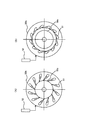
なお、本実施例のターボチャージャ50は、過給圧を所望の圧力とすべくタービンに吹き付けられる排気の流速をノズルベーンの開度を変更することにより可変とする可変容量型ターボチャージャを採用している。図2は、可変容量型ターボチャージャの構成を示す断面図である。図2(A)はノズルベーン51が開いている場合を示し、図2(B)はノズルベーン51が閉じている場合を示している。
The
可変容量型ターボチャージャは、図に示すように、タービンハウジング50b内に設けられたタービンインペラ50cの周囲に複数のノズルベーン51を備えて構成されている。このノズルベーン51は、アクチュエータ52により開閉される。このノズルベーン51を閉じ側へ回動させると、隣接するノズルベーン51間の間隙が狭くなり、ノズルベーン51間の流路が閉じられることになる。一方、ノズルベーン51を開き側へ回動すると、隣接するノズルベーン51間の間隙が広くなり、ノズルベーン51間の流路が開かれることになる。
As shown in the figure, the variable displacement turbocharger is configured to include a plurality of
このように構成された可変容量型ターボチャージャでは、アクチュエータ52によってノズルベーン51の回動方向と回動量とを調節することにより、ノズルベーン51間の流路の向き、及びノズルベーン51間の間隙を変更することが可能となる。即ち、ノズルベーン51の回動方向と回動量とを制御することにより、タービンインペラ50cに吹き付けられる排気の方向、流速、量が調節されることになる。これにより、過給圧を調節することができる。また、このときに排気の圧力が変化する。
In the variable displacement turbocharger configured as described above, the direction of the flow path between the
また、内燃機関1には、排気管8内を流通する排気の一部(以下、EGRガスという。)を吸気管4へ再循環させるEGR装置30が備えられている。このEGR装置30は、EGR通路31、EGR弁32を備えて構成されている。
Further, the internal combustion engine 1 is provided with an
EGR通路31は、タービンハウジング50bよりも上流側の排気管8と、コンプレッサハウジング50aよりも下流側の吸気管4と、を接続している。このEGR通路31を通って、EGRガスが再循環される。また、EGR弁32は、EGR通路31の通路断面積を調整することにより、該EGR通路31を流れるEGRガスの量を調整する。
The
さらに、コンプレッサハウジング50aよりも下流側の吸気管4の途中には、該吸気管4内を流れるガスの圧力に応じた信号を出力する過給圧センサ96と、該吸気管4内を流れるガスの温度に応じて信号を出力する吸気温度センサ97と、が取り付けられている。なお、本実施例においては過給圧センサ96が、本発明における過給圧測定手段に相当する。
Further, in the middle of the
そして、内燃機関1には、該内燃機関1を制御するための電子制御ユニットであるECU90が併設されている。このECU90は、CPUの他、各種のプログラム及びマップを記憶するROM、RAM等を備えており、内燃機関1の運転条件や運転者の要求に応じて内燃機関1の運転状態等を制御するユニットである。
The internal combustion engine 1 is also provided with an
ここで、上記センサの他、アクセル開度センサ91およびクランクポジションセンサ92、さらには大気圧センサ94がECU90と電気的に接続されている。ECU90はアクセル開度センサ91からアクセル開度に応じた信号を受け取り、この信号に応じて内燃機関1に要求される機関負荷等を算出する。また、ECU90はクランクポジションセンサ92から内燃機関1の出力軸の回転角に応じた信号を受け取り、内燃機関1の機関回転速度を算出する。さらに、ECU90は大気圧センサ94から大気の圧力に応じた信号を受け取り、大気圧を算出する。なお、本実施例では大気圧センサ94が、本発明における大気圧測定手段に相当する。
Here, in addition to the above sensors, an
一方、ECU90には、排気側VVT26、EGR弁32、アクチュエータ52、燃料噴射弁82が電気配線を介して接続されており、該ECU90によりこれらの機器が制御される。
On the other hand, the
ここで、ターボチャージャ50を備えたディーゼル機関で高地走行をする場合には、大気圧の低下により吸気の流量が低下するため、ターボチャージャ50がする仕事も低下す
る。このため、平地走行時と比較すると過給圧が低くなるため、気筒2内の圧力も低くなるので、排気弁9の最適開弁時期が変化する。
Here, when traveling at a high altitude with a diesel engine equipped with the
また、本実施例のような可変容量型ターボチャージャ50を備えたディーゼル機関では、高地走行等で大気圧が低下したときに、吸入空気量を要求値に合わせるためにノズルベーン51が閉じ側とされる。つまり、ノズルベーン51を閉じ側として過給圧を増加させることにより吸入空気量の増加を図る。これにより、大気圧が低下して減少した分の吸入空気量を補うことができる。しかし、ノズルベーン51が閉じられると、該ノズルベーン51よりも上流側の排気の圧力が上昇する。このときに、過給圧の上昇度合いよりも排気の圧力の上昇度合いのほうが大きくなるため、排気弁9の最適開弁時期が変化する。これは、過給圧の低下の度合いよりも、排気の圧力の低下の度合いのほうが小さいため、排気弁9の最適開弁時期が変化するともいえる。
Further, in the diesel engine equipped with the
図3は、膨張行程から排気行程にかけての気筒内圧力と気筒内容積との関係を示した図である。破線は平地における最適時期(気筒内容積がV1のとき)に排気弁9を開いた場合、実線は高地における最適時期(気筒内容積がV2のとき)に排気弁9を開いた場合、一点鎖線は高地において平地における最適時期(気筒内容積がV1のとき)に排気弁9を開いた場合を示している。
FIG. 3 is a graph showing the relationship between the cylinder pressure and the cylinder volume from the expansion stroke to the exhaust stroke. A broken line indicates a case where the
高地において平地における最適時期に排気弁9を開いた場合(一点鎖線)では、気筒2内の圧力が早い段階から低下して正の仕事が減少する一方で、排気行程における負の仕事が増加する。このときには、膨張仕事(正の仕事)の減少を、押出損失(負の仕事)の増加が上回るため、高地における最適時期に排気弁9を開いた場合(実線)と比較して、全体としての効率が低下する。
When the
高地においては、ノズルベーン51が閉じられることによる排気の圧力の上昇が顕著であるため、排気弁9の開弁時期を平地よりも遅くしたほうが、全体としての効率の低下を抑制できる。
At high altitudes, the increase in exhaust pressure due to the closing of the
ここで、図4は、機関回転数と排気弁の最適開弁時期と走行場所との関係を示した図である。機関回転数の全域において、平地と比較して高地となるほど排気弁9の最適開弁時期が遅くなる。これは、排気弁9の最適開弁時期が下死点に近づくともいえる。
Here, FIG. 4 is a diagram showing the relationship between the engine speed, the optimal valve opening timing of the exhaust valve, and the travel location. In the whole engine speed range, the optimum valve opening timing of the
つまり、膨張行程における正の仕事をより大きくし、排気行程における負の仕事をより小さくするように排気弁9の開弁時期を変更する。このようにすることで、内燃機関1の効率を高めることができるため、燃費の悪化を抑制できる。
That is, the valve opening timing of the
すなわち、過給圧が低下することにより膨張行程における正の仕事が小さくなるため、正の仕事がより大きくなるようにする。さらに、排気の圧力が上昇することにより排気行程における負の仕事が大きくなるため、負の仕事がより小さくなるようにする。この正の仕事と、負の仕事と、を考慮して、内燃機関1の効率が最も高くなるように排気弁9の最適開弁時期を決定している。
That is, since the positive work in the expansion stroke is reduced as the supercharging pressure is lowered, the positive work is made larger. Further, since the negative work in the exhaust stroke increases as the exhaust pressure increases, the negative work is made smaller. Considering this positive work and negative work, the optimal valve opening timing of the
そして、過給圧及び排気の圧力を用いて排気弁9の最適開弁時期を決定することができる。図5は、本実施例における排気弁の最適開弁時期を決定するフローを示したフローチャートである。本ルーチンはECU13により、所定の時間毎に繰り返し実行される。
The optimum valve opening timing of the
ステップS101では、大気圧が取得される。つまり、大気圧センサ94の出力値が読み込まれる。
In step S101, the atmospheric pressure is acquired. That is, the output value of the
ステップS102では、過給圧が取得される。つまり、過給圧センサ96の出力値が読み込まれる。
In step S102, the supercharging pressure is acquired. That is, the output value of the supercharging
ステップS103では、ターボチャージャ50がする仕事(ターボ仕事)が算出される。ここでは、ガスがコンプレッサハウジング50aを通過する際にどれだけの仕事を与えたかを算出する。このときに、過給圧と大気圧とに基づいて仕事が算出される。つまり、コンプレッサハウジング50aよりも下流側のガスのエンタルピと、上流側のガスのエンタルピと、の差に基づいてターボ仕事を算出する。本実施例においてはステップS103を処理するECU90が、本発明におけるターボ仕事算出手段に相当する。
In step S103, the work (turbo work) performed by the
ステップS104では、気筒2内へ吸入されるガス量が算出される。これは、新気量とEGRガス量とを加えた量となる。例えば、気筒2内へ吸入されるガス量は、吸気温度と過給圧とに応じて変化するため、これらの関係を予め実験等により求めておいても良い。つまり、吸気温度と過給圧とが分かれば、気筒2内にどれだけのガスが吸入されるのか分かる。また、エアフローメータ95により、新気量を求めることもできる。同様にして、EGRガス量を求めても良い。なお、本実施例においてはステップS104を処理するECU90が、本発明におけるガス量算出手段に相当する。
In step S104, the amount of gas sucked into the
ステップS105では、タービンハウジング50bよりも上流側の排気の圧力が算出される。これは、気筒2から排出されるガスに残っているエネルギに基づいて算出される。つまり、気筒2内へ吸入されるガス量および気筒2内に入るエネルギに基づいて、排気中にはどの程度のエネルギが残っているのかを算出する。このときに燃料噴射量を考慮する。また、気筒2内へ吸入されるガス量は、ステップS104で求めた値である。気筒2内に入るエネルギは、ステップS103で算出されるターボ仕事に基づいて得る。燃料噴射量は、ECU13により算出される値(指令値)を用いる。これらの関係は予め実験等により求めておいても良い。なお、本実施例においてはステップS105を処理するECU90が、本発明における排気圧力推定手段に相当する。
In step S105, the exhaust pressure upstream of the
ステップS106では、排気弁9の最適開弁時期が算出される。ここでは、過給圧と排気の圧力とに基づいて、排気弁9の最適開弁時期が算出される。つまり、大気圧が低くなるほど、過給圧の上昇よりも排気の圧力の上昇のほうが大きくなるため、これらの値に応じて排気弁9の開弁時期を下死点側に近づける。これらの関係は予め実験等により求めておいても良い。なお、本実施例においてはステップS106を処理するECU90が、本発明における決定手段に相当する。
In step S106, the optimal valve opening timing of the
ステップS107では、排気弁9の開弁時期が変更される。つまり、排気弁9の開弁時期がステップS106で得られた最適開弁時期となるように、ECU13は排気側VVT26を制御する。このようにして、排気弁9の開弁時期を適正化することができる。
In step S107, the opening timing of the
なお、ステップS105で算出される排気の圧力に基づいて、膨張行程中の気筒2内の圧力を算出することもできる。ここで、膨張行程では断熱変化をしていると仮定する。そうすると、排気弁9の開弁時の排気の圧力と、クランク角度と、該クランク角度に対する気筒2内の容積と、から逆算していけば、膨張行程中のクランク角度毎の気筒2内の圧力を算出することができる。
The pressure in the
また、排気弁9の最適開弁時期は、大気圧と関連付けて予め実験等により求めてマップ化しておくことができる。つまり、大気圧を測定してこのマップに代入することにより最適開弁時期を求めることができる。さらに、気筒2内の圧力を測定するセンサを備えている場合には、気筒2内の圧力と大気圧とに応じて排気弁9の最適開弁時期を求めることもできる。
Further, the optimum valve opening timing of the
1 内燃機関
2 気筒
3 吸気ポート
4 吸気管
5 吸気弁
6 吸気側カム
7 排気ポート
8 排気管
9 排気弁
10 シリンダヘッド
11 排気側カム
13 クランクシャフト
14 コンロッド
15 ピストン
25 排気側カムシャフト
27 排気側プーリ
26 排気側VVT
30 EGR装置
31 EGR通路
32 EGR弁
50 ターボチャージャ
50a コンプレッサハウジング
50b タービンハウジング
50c タービンインペラ
51 ノズルベーン
52 アクチュエータ
82 燃料噴射弁
90 ECU
91 アクセル開度センサ
92 クランクポジションセンサ
94 大気圧センサ
95 エアフローメータ
96 過給圧センサ
97 吸気温度センサ
Reference Signs List 1
30
91
Claims (2)
ターボチャージャと、
内燃機関の過給圧を測定する過給圧測定手段と、
排気の圧力を推定する排気圧力推定手段と、
前記排気弁の開弁時期を過給圧と排気の圧力とに応じて決定する決定手段と、
を備えることを特徴とする内燃機関の制御装置。 A variable valve mechanism for changing the opening timing of the exhaust valve of the internal combustion engine;
Turbocharger,
Supercharging pressure measuring means for measuring the supercharging pressure of the internal combustion engine;
Exhaust pressure estimating means for estimating the pressure of the exhaust;
Determining means for determining a valve opening timing of the exhaust valve according to a supercharging pressure and an exhaust pressure;
A control device for an internal combustion engine, comprising:
前記過給圧測定手段により測定される過給圧と前記大気圧測定手段により測定される大気圧とに基づいて、ターボチャージャがした仕事を算出するターボ仕事算出手段と、
内燃機関の気筒内に吸入されるガス量を算出するガス量算出手段と、
を備え、
前記排気圧力推定手段は、前記ターボ仕事算出手段により算出される仕事と前記ガス量算出手段により算出されるガス量とに基づいて排気の圧力を算出することを特徴とする請求項1に記載の内燃機関の制御装置。 Atmospheric pressure measuring means for measuring atmospheric pressure;
Turbo work calculating means for calculating work performed by the turbocharger based on the supercharging pressure measured by the supercharging pressure measuring means and the atmospheric pressure measured by the atmospheric pressure measuring means;
Gas amount calculating means for calculating the amount of gas sucked into the cylinder of the internal combustion engine;
With
The exhaust gas pressure estimating means calculates the pressure of the exhaust gas based on the work calculated by the turbo work calculating means and the gas amount calculated by the gas amount calculating means. Control device for internal combustion engine.
Priority Applications (1)
| Application Number | Priority Date | Filing Date | Title |
|---|---|---|---|
| JP2008223456A JP5029538B2 (en) | 2008-09-01 | 2008-09-01 | Control device for internal combustion engine |
Applications Claiming Priority (1)
| Application Number | Priority Date | Filing Date | Title |
|---|---|---|---|
| JP2008223456A JP5029538B2 (en) | 2008-09-01 | 2008-09-01 | Control device for internal combustion engine |
Publications (2)
| Publication Number | Publication Date |
|---|---|
| JP2010059796A true JP2010059796A (en) | 2010-03-18 |
| JP5029538B2 JP5029538B2 (en) | 2012-09-19 |
Family
ID=42186872
Family Applications (1)
| Application Number | Title | Priority Date | Filing Date |
|---|---|---|---|
| JP2008223456A Expired - Fee Related JP5029538B2 (en) | 2008-09-01 | 2008-09-01 | Control device for internal combustion engine |
Country Status (1)
| Country | Link |
|---|---|
| JP (1) | JP5029538B2 (en) |
Cited By (1)
| Publication number | Priority date | Publication date | Assignee | Title |
|---|---|---|---|---|
| JP2013032740A (en) * | 2011-08-02 | 2013-02-14 | Toyota Central R&D Labs Inc | Control device of internal combustion engine |
Citations (3)
| Publication number | Priority date | Publication date | Assignee | Title |
|---|---|---|---|---|
| JPH1162639A (en) * | 1997-08-25 | 1999-03-05 | Hitachi Ltd | Control device for engine |
| JP2003003871A (en) * | 2001-06-20 | 2003-01-08 | Hitachi Unisia Automotive Ltd | Variable valve gear for internal combustion engine with supercharger |
| JP2004257315A (en) * | 2003-02-26 | 2004-09-16 | Toyota Motor Corp | Status detector of internal combustion engine |
-
2008
- 2008-09-01 JP JP2008223456A patent/JP5029538B2/en not_active Expired - Fee Related
Patent Citations (3)
| Publication number | Priority date | Publication date | Assignee | Title |
|---|---|---|---|---|
| JPH1162639A (en) * | 1997-08-25 | 1999-03-05 | Hitachi Ltd | Control device for engine |
| JP2003003871A (en) * | 2001-06-20 | 2003-01-08 | Hitachi Unisia Automotive Ltd | Variable valve gear for internal combustion engine with supercharger |
| JP2004257315A (en) * | 2003-02-26 | 2004-09-16 | Toyota Motor Corp | Status detector of internal combustion engine |
Cited By (1)
| Publication number | Priority date | Publication date | Assignee | Title |
|---|---|---|---|---|
| JP2013032740A (en) * | 2011-08-02 | 2013-02-14 | Toyota Central R&D Labs Inc | Control device of internal combustion engine |
Also Published As
| Publication number | Publication date |
|---|---|
| JP5029538B2 (en) | 2012-09-19 |
Similar Documents
| Publication | Publication Date | Title |
|---|---|---|
| JP4623064B2 (en) | Control device for an internal combustion engine with a supercharger | |
| JP4306703B2 (en) | Control device for an internal combustion engine with a supercharger | |
| JP4375369B2 (en) | Control device for an internal combustion engine with a supercharger | |
| JP5389238B1 (en) | Waste gate valve control device for internal combustion engine | |
| JP4816811B2 (en) | Control device for internal combustion engine | |
| JP2009002283A (en) | Control system of internal combustion engine | |
| CN110360014B (en) | Control apparatus for internal combustion engine | |
| JP6544367B2 (en) | Control device for internal combustion engine | |
| US20180266365A1 (en) | Exhaust gas control apparatus of internal combustion engine | |
| JP2010024974A (en) | Control device of internal combustion engine with supercharger | |
| US11187166B2 (en) | Internal combustion engine and method of controlling same | |
| CN112664282B (en) | Control method for variable turbocharger | |
| JP2013096247A (en) | Control device of internal combustion engine | |
| JP6017304B2 (en) | Supercharging system and control method of supercharging system | |
| US10584649B2 (en) | Control device for internal combustion engine | |
| JP2007303380A (en) | Exhaust gas control device for internal combustion engine | |
| JP6544363B2 (en) | Control device for internal combustion engine | |
| JP5029538B2 (en) | Control device for internal combustion engine | |
| JP5608614B2 (en) | Engine EGR flow rate detection device | |
| JP5589687B2 (en) | Engine control device | |
| JP5018974B2 (en) | Control device for internal combustion engine | |
| EP2354501B1 (en) | Control apparatus for internal combustion engine | |
| JP2010185302A (en) | Control device for internal combustion engine | |
| JP2016138502A (en) | Cylinder deactivation control device for internal combustion engine | |
| JP2011179472A (en) | Internal-combustion engine controller |
Legal Events
| Date | Code | Title | Description |
|---|---|---|---|
| A621 | Written request for application examination |
Free format text: JAPANESE INTERMEDIATE CODE: A621 Effective date: 20101214 |
|
| A977 | Report on retrieval |
Free format text: JAPANESE INTERMEDIATE CODE: A971007 Effective date: 20120124 |
|
| A131 | Notification of reasons for refusal |
Free format text: JAPANESE INTERMEDIATE CODE: A131 Effective date: 20120221 |
|
| A521 | Request for written amendment filed |
Free format text: JAPANESE INTERMEDIATE CODE: A523 Effective date: 20120405 |
|
| TRDD | Decision of grant or rejection written | ||
| A01 | Written decision to grant a patent or to grant a registration (utility model) |
Free format text: JAPANESE INTERMEDIATE CODE: A01 Effective date: 20120529 |
|
| A01 | Written decision to grant a patent or to grant a registration (utility model) |
Free format text: JAPANESE INTERMEDIATE CODE: A01 |
|
| A61 | First payment of annual fees (during grant procedure) |
Free format text: JAPANESE INTERMEDIATE CODE: A61 Effective date: 20120611 |
|
| R151 | Written notification of patent or utility model registration |
Ref document number: 5029538 Country of ref document: JP Free format text: JAPANESE INTERMEDIATE CODE: R151 |
|
| FPAY | Renewal fee payment (event date is renewal date of database) |
Free format text: PAYMENT UNTIL: 20150706 Year of fee payment: 3 |
|
| LAPS | Cancellation because of no payment of annual fees |