JP2010058364A - Apparatus for water-cooling hollow extruded article - Google Patents
Apparatus for water-cooling hollow extruded article Download PDFInfo
- Publication number
- JP2010058364A JP2010058364A JP2008225720A JP2008225720A JP2010058364A JP 2010058364 A JP2010058364 A JP 2010058364A JP 2008225720 A JP2008225720 A JP 2008225720A JP 2008225720 A JP2008225720 A JP 2008225720A JP 2010058364 A JP2010058364 A JP 2010058364A
- Authority
- JP
- Japan
- Prior art keywords
- water
- tank
- reduced
- extruded product
- sizer
- Prior art date
- Legal status (The legal status is an assumption and is not a legal conclusion. Google has not performed a legal analysis and makes no representation as to the accuracy of the status listed.)
- Granted
Links
- 238000001816 cooling Methods 0.000 title claims abstract description 127
- XLYOFNOQVPJJNP-UHFFFAOYSA-N water Substances O XLYOFNOQVPJJNP-UHFFFAOYSA-N 0.000 claims abstract description 240
- 238000004513 sizing Methods 0.000 claims abstract description 59
- 239000000498 cooling water Substances 0.000 claims abstract description 38
- 235000012438 extruded product Nutrition 0.000 claims description 68
- 238000003780 insertion Methods 0.000 claims description 14
- 230000037431 insertion Effects 0.000 claims description 14
- 238000001125 extrusion Methods 0.000 claims description 10
- 230000002093 peripheral effect Effects 0.000 claims description 10
- 125000006850 spacer group Chemical group 0.000 claims description 7
- 238000000034 method Methods 0.000 claims description 5
- 230000008569 process Effects 0.000 claims description 5
- 239000000758 substrate Substances 0.000 claims description 4
- 230000000149 penetrating effect Effects 0.000 claims description 3
- 230000008859 change Effects 0.000 abstract description 9
- 230000007423 decrease Effects 0.000 abstract description 5
- 238000005452 bending Methods 0.000 abstract description 4
- 230000001788 irregular Effects 0.000 abstract description 4
- 238000000465 moulding Methods 0.000 abstract 1
- 230000009471 action Effects 0.000 description 6
- 238000002347 injection Methods 0.000 description 5
- 239000007924 injection Substances 0.000 description 5
- 238000004519 manufacturing process Methods 0.000 description 5
- 230000001105 regulatory effect Effects 0.000 description 5
- 238000005520 cutting process Methods 0.000 description 4
- 230000006837 decompression Effects 0.000 description 4
- 229920005989 resin Polymers 0.000 description 4
- 239000011347 resin Substances 0.000 description 4
- 229920003002 synthetic resin Polymers 0.000 description 4
- 239000000057 synthetic resin Substances 0.000 description 4
- 230000009467 reduction Effects 0.000 description 3
- 238000007789 sealing Methods 0.000 description 3
- 238000003860 storage Methods 0.000 description 3
- 239000002184 metal Substances 0.000 description 2
- 230000001603 reducing effect Effects 0.000 description 2
- 238000011144 upstream manufacturing Methods 0.000 description 2
- 238000009423 ventilation Methods 0.000 description 2
- 238000005273 aeration Methods 0.000 description 1
- 238000004891 communication Methods 0.000 description 1
- 238000013461 design Methods 0.000 description 1
- 230000000694 effects Effects 0.000 description 1
- 239000011521 glass Substances 0.000 description 1
- 230000005484 gravity Effects 0.000 description 1
- 230000007246 mechanism Effects 0.000 description 1
- 238000012856 packing Methods 0.000 description 1
- 238000005192 partition Methods 0.000 description 1
- 238000003825 pressing Methods 0.000 description 1
- 230000000630 rising effect Effects 0.000 description 1
- 239000003566 sealing material Substances 0.000 description 1
- 239000008399 tap water Substances 0.000 description 1
- 235000020679 tap water Nutrition 0.000 description 1
Images


Classifications
-
- B—PERFORMING OPERATIONS; TRANSPORTING
- B29—WORKING OF PLASTICS; WORKING OF SUBSTANCES IN A PLASTIC STATE IN GENERAL
- B29C—SHAPING OR JOINING OF PLASTICS; SHAPING OF MATERIAL IN A PLASTIC STATE, NOT OTHERWISE PROVIDED FOR; AFTER-TREATMENT OF THE SHAPED PRODUCTS, e.g. REPAIRING
- B29C48/00—Extrusion moulding, i.e. expressing the moulding material through a die or nozzle which imparts the desired form; Apparatus therefor
- B29C48/03—Extrusion moulding, i.e. expressing the moulding material through a die or nozzle which imparts the desired form; Apparatus therefor characterised by the shape of the extruded material at extrusion
- B29C48/09—Articles with cross-sections having partially or fully enclosed cavities, e.g. pipes or channels
-
- B—PERFORMING OPERATIONS; TRANSPORTING
- B29—WORKING OF PLASTICS; WORKING OF SUBSTANCES IN A PLASTIC STATE IN GENERAL
- B29C—SHAPING OR JOINING OF PLASTICS; SHAPING OF MATERIAL IN A PLASTIC STATE, NOT OTHERWISE PROVIDED FOR; AFTER-TREATMENT OF THE SHAPED PRODUCTS, e.g. REPAIRING
- B29C48/00—Extrusion moulding, i.e. expressing the moulding material through a die or nozzle which imparts the desired form; Apparatus therefor
- B29C48/25—Component parts, details or accessories; Auxiliary operations
- B29C48/88—Thermal treatment of the stream of extruded material, e.g. cooling
- B29C48/90—Thermal treatment of the stream of extruded material, e.g. cooling with calibration or sizing, i.e. combined with fixing or setting of the final dimensions of the extruded article
- B29C48/905—Thermal treatment of the stream of extruded material, e.g. cooling with calibration or sizing, i.e. combined with fixing or setting of the final dimensions of the extruded article using wet calibration, i.e. in a quenching tank
-
- B—PERFORMING OPERATIONS; TRANSPORTING
- B29—WORKING OF PLASTICS; WORKING OF SUBSTANCES IN A PLASTIC STATE IN GENERAL
- B29C—SHAPING OR JOINING OF PLASTICS; SHAPING OF MATERIAL IN A PLASTIC STATE, NOT OTHERWISE PROVIDED FOR; AFTER-TREATMENT OF THE SHAPED PRODUCTS, e.g. REPAIRING
- B29C48/00—Extrusion moulding, i.e. expressing the moulding material through a die or nozzle which imparts the desired form; Apparatus therefor
- B29C48/25—Component parts, details or accessories; Auxiliary operations
- B29C48/88—Thermal treatment of the stream of extruded material, e.g. cooling
- B29C48/911—Cooling
- B29C48/9115—Cooling of hollow articles
- B29C48/912—Cooling of hollow articles of tubular films
- B29C48/913—Cooling of hollow articles of tubular films externally
-
- B—PERFORMING OPERATIONS; TRANSPORTING
- B29—WORKING OF PLASTICS; WORKING OF SUBSTANCES IN A PLASTIC STATE IN GENERAL
- B29C—SHAPING OR JOINING OF PLASTICS; SHAPING OF MATERIAL IN A PLASTIC STATE, NOT OTHERWISE PROVIDED FOR; AFTER-TREATMENT OF THE SHAPED PRODUCTS, e.g. REPAIRING
- B29C48/00—Extrusion moulding, i.e. expressing the moulding material through a die or nozzle which imparts the desired form; Apparatus therefor
- B29C48/25—Component parts, details or accessories; Auxiliary operations
- B29C48/88—Thermal treatment of the stream of extruded material, e.g. cooling
- B29C48/919—Thermal treatment of the stream of extruded material, e.g. cooling using a bath, e.g. extruding into an open bath to coagulate or cool the material
Abstract
Description
本発明は、押出機より連続的に略水平方向へ押し出される合成樹脂パイプやチューブ等の中空押出成形物を水中に通過させて冷却硬化させるための水冷装置に関する。 The present invention relates to a water cooling apparatus for passing a hollow extruded product such as a synthetic resin pipe or a tube continuously extruded from an extruder in a substantially horizontal direction and allowing it to cool and cure.
一般的に、長尺の押出成形品の製造ラインでは、押出機から下流側に順次、水冷槽、引取り機、切断機が配置しており、押出機で加熱溶融した合成樹脂を押出機出口のダイを通して所要の断面形状として連続的に略水平方向へ押し出し、この高温の押出成形物を引取り機を介して引き取りながら、水冷槽の水中を通過させることによって冷却硬化させ、切断機で所定長さに切断して製品化する。 In general, in a production line for long extrudates, a water-cooled tank, a take-up machine, and a cutting machine are sequentially arranged downstream from the extruder, and the synthetic resin heated and melted by the extruder is discharged from the extruder. Extruded continuously in a substantially horizontal direction as a required cross-sectional shape through a die, and cooled and hardened by passing through the water in a water-cooled tank while taking out the high-temperature extrudate through the take-up machine, and predetermined with a cutting machine Cut into length and commercialize.
しかして、押出機から押し出された直後の高温で軟らかな押出成形物は自重によって変形し易いため、一般的にパイプやチューブ等の中空押出成形物では、押出機のマンドレル部で成形物の中空部に弱い空圧を送り込むことにより、その内圧でへたりを防止するようにしている。更に、中空押出成形物を対象として、水冷槽内を減圧にして水圧による変形を抑制すると共に、水冷槽の入口にサイザーを設け、押出成形物を該サイザーに通して水冷槽内に導入させて外形を規制することも行われている(特許文献1)。
しかしながら、近年における押出成形品の用途の広がりに伴い、特に精密機器や医療機器等に用いる合成樹脂パイプやチューブの如き中空押出成形品として、10μm台の高い寸法精度が要求されるようになっているが、押出直後の中空押出成形物は元来より形態的に変形し易く、従来の水冷槽による冷却方式では水冷槽の水中を進行して十分に冷却硬化する前に不規則な径変化や真円度の低下、曲がり等をきたすため、要求されるような高い寸法精度に仕上げることが困難な現状になっている。 However, with the spread of applications of extruded products in recent years, high dimensional accuracy of the order of 10 μm has been required as hollow extruded products such as synthetic resin pipes and tubes used especially for precision equipment and medical equipment. However, the hollow extruded product immediately after extrusion is more morphologically deformable than before, and in the conventional cooling method using a water-cooled tank, an irregular diameter change or In order to reduce the roundness, bend, etc., it is difficult to achieve the required high dimensional accuracy.
本発明は、上述の情況に鑑み、中空押出成形物の水冷装置として、該中空押出成形物が水冷槽の水中を進行して十分に冷却硬化するまでに不規則な径変化や真円度の低下、曲がり等を生じるのを防止でき、もって近年の要望に対処し得る高い寸法精度の中空押出成形品が得られるものを提供することを目的としている。 In view of the above situation, the present invention is a water cooling device for a hollow extruded product, which has irregular diameter changes and roundness until the hollow extruded product is sufficiently cooled and cured in water in a water cooling tank. An object of the present invention is to provide a hollow extruded product with high dimensional accuracy that can prevent the occurrence of lowering, bending, etc., and can cope with recent demands.
前記目的を達成するための手段を図面の参照符号を付して示せば、請求項1の発明に係る中空押出成形物の水冷装置は、押出機Eから連続的に略水平方向へ押し出される中空押出成形物Mを水中に通過させて冷却する減圧水冷槽1を備え、この減圧水冷槽1の成形物入口部に、減圧水冷槽1内に導入する前記中空押出成形物Mの外形を規制するアウトサイジングユニット2が嵌装されると共に、該減圧水冷槽1内へ冷却水Wを循環供給する冷却水循環供給手段と、該減圧水冷槽1内の上部に構成される空気層10を所定の減圧状態に設定する真空吸引手段とが付設され、前記アウトサイジングユニット2は、各々前記中空押出成形物Mを挿通させるサイジング孔21を有する複数個のサイザー部材20A〜20Hを有し、これらサイザー部材20A〜20Hが前記減圧水冷槽1内の水中においてサイジング孔21中心を同一軸線上に位置させて所定間隔置きに配列すると共に、これらサイザー部材20A〜20Hのサイジング孔径が後部側ほど縮径する形で複数段に変化しており、押出機Eから押し出されて減圧水冷槽1内を通過する中空押出成形物Mが、その中空内部の気圧によって張り切った状態を保ちつつ、前記複数個のサイザー部材20A〜20Hのサイジング孔21…を順次通過する過程で外径を絞られつつ冷却するように構成されてなる。
If the means for achieving the above object is shown with reference numerals in the drawings, the water cooling apparatus for hollow extruded products according to the invention of
請求項2の発明は、上記請求項1の中空押出成形物の水冷装置において、アウトサイジングユニット2は、中空押出成形物Mの進入口22を有して、前記減圧水冷槽1の前端壁1bに固着される入口ブロック部2aと、前記複数個のサイザー部材20A〜20Hを保持して該入口ブロック部2aに基端側を固着した多段サイジング部2bとを具備すると共に、入口ブロック部2aに前記進入口22を取り巻く冷却水通路23が設けられてなる構成としている。
According to a second aspect of the present invention, in the water cooling apparatus for a hollow extruded product according to the first aspect, the
請求項3の発明は、上記請求項1又は2の中空押出成形物の水冷装置において、アウトサイジングユニット2は、各々サイジング孔21を中心とするリング状に形成された前記複数個のサイザー部材20A〜20Hが、複数本の支持軸25…によって周辺部を支持され、且つ相互間にスペーサー24…を介して所定間隔に配置すると共に、前記支持軸25…に対して着脱可能に構成されてなる。
According to a third aspect of the present invention, in the water-cooling device for a hollow extruded product according to the first or second aspect, the
請求項4の発明は、上記請求項1〜3のいずれかの中空押出成形物の水冷装置において、最後尾に配置するサイザー部材20Hは、基板部20aから減圧水冷槽1の内奥側へ突出する筒状部20bを有し、該基板部20aから筒状部2b先端まで貫通する中心孔がサイジング孔21をなすと共に、該筒状部20bの全体にわたって内外を透通する多数の小孔20c…が形成されてなる構成としている。
According to a fourth aspect of the present invention, in the water-cooling device for a hollow extruded product according to any one of the first to third aspects, the
請求項5の発明は、上記請求項1〜3のいずれかの中空押出成形物の水冷装置において、アウトサイジングユニット2は、中空押出成形物Mのサンジング部(多段サイジング部2b)への進入口22の外側に、少なくとも該進入口22が浸漬する水位まで冷却水Wを収容するフロントバス部2cを備え、押出機Eから押し出される中空押出成形物Mが該フロントバス部2cの水中を通過して減圧水冷槽1内に入るように構成されてなる。
According to a fifth aspect of the present invention, in the water-cooling device for a hollow extruded product according to any one of the first to third aspects, the
請求項6の発明は、上記請求項5の中空押出成形物の水冷装置において、フロントバス部2cは、底部寄り位置より導入される冷却水Wがオーバーフローして外部へ排出するように構成されると共に、前端に中空押出成形物Mの挿通孔27aを有する挿通ガイド部材27が着脱交換可能に嵌装されてなる構成としている。
According to a sixth aspect of the present invention, in the water cooling apparatus for a hollow extruded product according to the fifth aspect, the
以下に、本発明の効果について、図面の参照符号を付して説明する。まず、請求項1の発明に係る水冷装置では、押出機Eから連続的に略水平方向へ押し出される中空押出成形物Mは、減圧水冷槽1内に入って水中を移動してゆくことで次第に冷却硬化するが、該減圧水冷槽1内の減圧によって水圧が軽減ないし相殺されるから、その中空内部の気圧によって張り切った状態を保ちつつ、該減圧水冷槽1の入口側において、アウトサイジングユニット2の複数個のサイザー部材20A〜20Hのサイジング孔21…を順次通過することにより、段階的に外径を絞られつつ冷却硬化してゆくから、該アウトサイジングユニット2を通過するまでの間に不規則な径変化や真円度の低下を生じることがなく、アウトサイジングユニット2を出た時点ではかなり硬化が進んで、特に冷却水Wに触れている外周部の硬さが増しているため、以降の減圧水冷槽1内の水中を移動する過程で径変化や真円度の低下を生じる懸念がなく、もって高い寸法精度を持つ中空押出成形品を製出できる。
The effects of the present invention will be described below with reference numerals in the drawings. First, in the water cooling apparatus according to the invention of
請求項2の発明によれば、アウトサイジングユニット2は、減圧水冷槽1の前端壁に固着される入口ブロック部2aと、前記複数個のサイザー部材20A〜20Hを保持した多段サイジング部2bとを具備するから、その組立製作及び減圧水冷槽1への組み付けが容易であり、また入口ブロック部2aの進入口22を取り巻く冷却水通路23により、当該入口ブロック部2aの昇温が抑えられると共に、その進入口22部分でも中空押出成形物Mに対する冷却作用を付与でき、アウトサイジング性がより向上する。
According to the invention of
請求項3の発明によれば、アウトサイジングユニット2は、各々中心にサイジング孔21を有するリング状の複数個のサイザー部材20A〜20Hがスペーサー24…を介して複数本の支持軸25…に周辺部で支持された構造であるから、これらサイザー部材20A〜20Hが相互間に所定間隔を保つ配置形態に簡単に組立製作できると共に、これらサイザー部材20A〜20Hが支持軸25…に対して着脱できるから、サイジング対象とする中空押出成形物Mの外径に応じて、サイザー部材20A〜20Hを対応するイジング孔径を有するものに容易に交換できると共に、中空押出成形物Mの樹脂種や性状に応じて、スペーサー24…の交換によるサイザー部材20A〜20Hの配置間隔の調整や、サイザー部材20A〜20Hの交換によるサイジング段数の変更を行うことも可能となる。
According to the invention of
請求項4の発明によれば、最後尾に配置するサイザー部材20Hのサイジング孔21が減圧水冷槽1の内奥側へ突出する筒状部20bの中心孔によって構成され、該筒状部20bの長手方向に沿って内外を透通する複数個の小孔20c…を有するから、アウトサイジングユニット2を通過する中空押出成形物Mは、かなり硬化が進んだサイジング最終段階で該筒状部20b内において、周囲の小孔20c…を介して減圧水冷槽1内の減圧作用と冷却水Wによる冷却作用を受けながら、連続的に外周部をサイジングされる結果、より高い寸法安定性が得られる。
According to invention of
請求項5の発明によれば、中空押出成形物Mがアウトサイジングユニット2のサンジング部(多段サイジング部2b)へ進入する前に、フロントバス部2cの水中を通過して降温するから、サンジング部でのサイジング作用がより安定して確実になされると共に、サンジング部への進入口22がフロントバス部2cの水Wによって水封される形になるから、外部の空気が該進入口22から気泡として減圧水冷槽1内へ侵入することがなく、もって減圧水冷槽1内の減圧状態を安定に維持できる。
According to the invention of
請求項6の発明によれば、フロントバス部2cが底部寄り位置より導入した冷却水Wをオーバーフローして外部へ排出する形であるため、水路構成が簡素になると共に、該フロントバス部2cの前端に設ける挿通ガイド部材27を適用する空押出成形物Mの外径に応じて挿通孔27aの径が適合するものに着脱交換できる。
According to the sixth aspect of the present invention, the
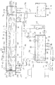
以下に、本発明の一実施形態に係る中空押出成形物の水冷装置について、図面を参照して具体的に説明する。図1は本発明の水冷装置を適用した中空押出成形物の製造ラインの概略側面図、図2は同水冷装置の配管系統を含む概略縦断側面図、図3は同水冷装置の減圧水冷槽の前端側の正面図、図4は同減圧水冷槽の前端部の水抜き状態での横断平面図、図5は同減圧水冷槽の前端部の縦断側面図、図6は同減圧水冷槽の前部側の縦断正面図である。 Below, the water cooling apparatus of the hollow extrusion molding which concerns on one Embodiment of this invention is demonstrated concretely with reference to drawings. FIG. 1 is a schematic side view of a production line of a hollow extruded product to which the water cooling apparatus of the present invention is applied, FIG. 2 is a schematic longitudinal side view including a piping system of the water cooling apparatus, and FIG. 3 is a reduced pressure water cooling tank of the water cooling apparatus. Front view of the front end side, FIG. 4 is a cross-sectional plan view of the front end portion of the reduced-pressure water cooling tank in a drained state, FIG. 5 is a longitudinal side view of the front end portion of the reduced-pressure water cooling tank, and FIG. It is a vertical front view of the part side.
図1に示す中空押出成形物の製造ラインでは、押出機Eから下流側に順次、水冷装置A、引取り機P、切断機Cが配置しており、押出機E内で加熱溶融した合成樹脂を該押出機E出口のダイDを通してパイプやチューブの如き所要の中空断面形状として連続的に略水平方向へ押し出し、この高温の中空押出成形物Mを引取り機Pを介して引き取りながら、水冷装置Cにおける減圧水冷槽1の水中を通過させることによって冷却硬化させ、切断機Cで所定長さに切断して製品化するようになっている。
In the production line for the hollow extruded product shown in FIG. 1, a water-cooling device A, a take-up machine P, and a cutting machine C are sequentially arranged downstream from the extruder E, and the synthetic resin heated and melted in the extruder E. Is continuously extruded in a substantially horizontal direction through a die D at the outlet of the extruder E as a required hollow cross-sectional shape such as a pipe or tube, and the high-temperature hollow extruded product M is taken out via the take-up machine P while being cooled with water. It cools and hardens by letting the water of the pressure-reduced
図2でも示すように、水冷装置Aは、水平方向に長尺な箱状で密閉式の減圧水冷槽1の前端に、アウトサイジングユニット2が嵌装されると共に、該減圧水冷槽1の下方に、横長直方体形状で密閉式の調整水槽3と、同じく横長直方体形状で上方へ開放した貯水槽4とが配置し、また該減圧水冷槽1の側方に、水冷却手段としての冷水器5が配置している。
As shown also in FIG. 2, the water cooling apparatus A has a horizontally long box-like closed sealed water-cooled
減圧水冷槽1は、内部の前部側に、各々上端を開口した溢流パイプ61及び通気パイプ62が槽体11の内底から垂直に立設されている。しかして、通気パイプ62の上端は溢流パイプ61の上端よりも高位に設定され、減圧水冷槽1内には冷却用の水Wが溢流パイプ61の開口位置で規制される水位で収容され、その上部側が空気層10をなしている。また、減圧水冷槽1の底部には、各々長手方向に所定間隔を置いて、複数の水導入口13及び水導出口14a,14bが設けてある。更に、この減圧水冷槽1には、槽前部側の水温を測定表示する水温計WT、空気層10に繋がる真空調整弁CV、空気層10の圧力を計測する真空圧力計PG、真空圧力計PGの計測値に応じて作動・停止する自動圧力調整弁OVがそれぞれ付設されている。
In the reduced-pressure water-cooled
一方、減圧水冷槽1の出口側である後端には、槽体11の延長部としてシール槽7が一体形成され、該シール槽7と減圧水冷槽1との隔壁7aならびに該シール槽7の後端壁7bには、中空押出成形物Mを液密に通過させるシール材71が嵌装されている。そして、シール槽7内にも、上端を槽頂部近くに開口した溢流パイプ63が内底から垂直に立設されると共に、底部に水導入口72が設けてある。
On the other hand, a
図3〜図5に示すように、アウトサイジングユニット2は、減圧水冷槽1における槽体11の前端壁11aの外側に配置した入口ブロック部2aと、この入口ブロック部2aの内端部に基端側を螺着して、前端壁11aの開口部11bより減圧水冷槽1の内奥側へ突入配置した多段サイジング部2bと、入口ブロック部2aの前面側に配置したフロントバス部2cとで構成されている。
As shown in FIGS. 3 to 5, the
入口ブロック部2aは、内端中央側の環状凸部201aを減圧水冷槽1の前端壁11aの開口部11bに嵌合して、内端周辺側で環状ガスケット28を介して該前端壁11aにねじ止めされた取付基盤201と、この取付基盤201の外面側にねじ止めされた環状前板202とで構成され、取付基盤201及び環状前板202の両者にわたる中心位置に、環状前板202側で前方へラッパ状に開く進入口22が貫設されている。
The
多段サイジング部2bは、各々中心にサイジング孔21を有するリング状の複数(図では8個)のサイザー部材20A〜20Hと、その最前端のサイザー部材20Aの後端面に前端ねじ部25aを螺着して平行配置し、他のサイザー部材20B〜20Hの周辺部を貫通する複数本の角棒状の支持軸25…と、各支持軸25に挿嵌されてサイザー部材20A〜20Hの相互間に介在する筒状のスペーサー24…と、各支持軸25の後端ねじ部25bに螺着した締付ナット26…とで構成され、これら締付ナット26…の締め付けによってサイザー部材20A〜20Hのサイジング孔21…の中心が同一軸線上に位置する状態で一体化している。
The
ここで、サイザー部材20A〜20Hのサイジング孔21…は、全部が同じ孔径ではなく、後部側ほど縮径するように複数段に変化するものとする。例えば、最終的な中空押出成形品の設定外径が3.80mmであるとき、サイジング孔径は、サイザー部材20A〜20Eで4.10mm、サイザー部材20F,20Gで4.05mm、サイザー部材20Hで3.96mmと3段階とする。なお、この場合の最後尾のサイザー部材20Hによるサイジング径3.96mmから設定外径3.80mmへの変化は、アウトサイジングユニット2を出てから減圧水冷槽1の水中を移動する過程での中空押出成形物Mの冷却硬化に伴う自然収縮によってなされる。
Here, it is assumed that the sizing holes 21 of the
しかして、多段サイジング部2bの最前端のサイザー部材20Aは、外周に雄ねじ203を有すると共に、前端中央部に内側をサイジング孔21とする筒状部204を有しており、この筒状部204を入口ブロック部2aの進入口22に挿嵌させる形で、外周の雄ねじ203を入口ブロック部2aの内周雌ねじ部201bに螺合することにより、当該多段サイジング部2bを入口ブロック部2aに連結している。また、入口ブロック部2aの取付基盤201と環状前板202との間、ならびに該取付基盤201と多段サイジング部2bの最前端のサイザー部材20Aとの間には、それぞれ入口ブロック部2aの進入口22を取り巻く冷却水通路23,23が構成され、該入口ブロック部2aに形成された出入孔23a…を介して外部から冷却水Wを両冷却水通路23,23に循環供給するようになっている。なお、サイザー部材20Aの筒状部204の外周と入口ブロック部2aの進入口22の内周との間、冷却水通路23よりも外周側における該サイザー部材20Aと入口ブロック部2aの取付基盤201との対接面、同じく冷却水通路23よりも外周側における入口ブロック部2aの取付基盤201と環状前板202との間、にはそれぞれシールリング205が介装されている。
Thus, the
フロントバス部2cは、入口ブロック部2aの前面にねじ止めされた槽基枠206と、この槽基枠206の前端にねじ止めされたU字形の端板207と、該端板207のU字形の中央凹陥部207aを塞ぐ挿通ガイド部材27とにより、上方へ開放したフロントバス29を構成している。しかして、挿通ガイド部材27は、中心に中空押出成形物Mの挿通孔27aを備えた円板状をなし、端板207にねじ止めされる馬蹄形の押さえ枠208を介して該端板207の前面側に嵌装されている。また、端板207には、フロントバス29の底部寄りに位置して、水導入口29a,29a(図3,図5参照)が穿設されており、外部から供給される冷却水Wを水導入口29a,29aよりフロントバス29内に連続的に導入すると共に、余剰の水Wがフロントバス29の上縁29bよりオーバーフローして外側へ流出するようになっている。なお、減圧水冷槽1の前端下部には、アウトサイジングユニット2の入口ブロック部2a及びフロントバス部2cの下方側全体をカバーする水受けトレイ210が張設されており、フロントバス29よりオーバーフローした水Wを該水受けトレイ210で受け、排水管211より排出するようになっている。
The
一方、図6で詳細に示すように、減圧水冷槽1の内底部には断面T字形のガイド取付レール15が長手方向に沿って配設されており、このガイド取付レール15には略L字形の複数のガイド支持枠16…が所定間隔置きに嵌装されている。そして、各ガイド支持枠16の垂直片16aの上部に、糸巻形のガイドローラー17を回転自在に枢支した水平支軸17aが保持されており、中空押出成形物Mがこれらガイドローラー17…の下側を通って浮上防止されながら該減圧水冷槽1内の水中を移動するように設定されている。なお、ガイド支持枠16は、下端のコ字枠部16aをガイド取付レール15に摺動自在に嵌合し、固定ねじ15cの締め付けによって任意の位置で固定できると共に、垂直片16aにおける水平支軸17aの保持位置を中空押出成形物Mの外径に応じて上下に調整できる構造になっている。また、溢流パイプ61及び通気パイプ62は、パイプ本体61a,62aの頂部に、上端を斜め切りした短筒状の筒口部材61b,62bが上下摺動自在に外嵌し、これら筒口部材61b,62bを蝶ねじ61c,62cの締め付けによって所定高さで固定するようにしている。
On the other hand, as shown in detail in FIG. 6, a
減圧水冷槽1の槽体11は、上方に開放しており、その内向きにコ字形に曲成した上縁部11aの上面側に貼着したパッキング18を介して、該槽体11上にガラス製の蓋板19が載ることにより、内部が気密に保持される。しかして、減圧水冷槽1の全長は蓋板19の複数枚でカバーするように構成されており、各蓋板19は、外面側に幅方向に沿って止着した一対の金属帯板19a,19aの各一端側において、槽体11側に固着されたブラケット11bに枢支ピン19bを介して枢着されており、両金属帯板19a,19aの他端間に取り付けた把手19cを利用して開閉できるようになっている。
The
調整水槽3は、図2に示すように、減圧水冷槽1と同様に、所定の水位まで冷却水Wが収容され、内側上部が空気層30を構成している。そして、この調整水槽3の長手方向一端側において、当該調整水槽3内の冷却水Wを給水ポンプP1を介して減圧水冷槽1へ供給する給水管路L1が底部近傍から導出すると共に、上壁部に設けた吸気口31に空気層30の空気を真空ポンプVPを介して吸引する真空吸引管路VLが接続されている。ECは真空ポンプVPに繋がる大気放出器である。
As shown in FIG. 2, the
そして、給水管路L1は、給水ポンプP1に近い上流側に開閉弁SV及び流量計F1が介装され、下流側では複数に分岐し、その分岐した各管路が開閉弁SVを介して減圧水冷槽1の各水導入口13に接続している。また、真空ポンプVPの出口側には給水管路L1から分岐した注水管路L4を有しており、この注水管路L4から更に分岐した一方の管路L4aが開閉弁SVを介してシール槽7の水導入口72に接続されると共に、該注水管路L4から分岐した他方の管路L4bが図示を省略したサイジング用タンクへの注水路となり、該サイジング用タンクから冷却水がアウトサイジングユニット2の各部へ供給されるようになっている。
The water supply pipe L1 is provided with an on-off valve SV and a flow meter F1 on the upstream side close to the water supply pump P1, and is branched into a plurality on the downstream side, and each branched pipe is decompressed via the on-off valve SV. Each
一方、調整水槽3の長手方向他端側の上壁部には、下端が内底近くに開口した2本の導水管32が垂設されると共に、通気口34が設けてある。その導水管32の一本には減圧水冷槽1の溢流パイプ61に繋がる溢流管路L2が接続され、他の一本には減圧水冷槽1の水導出口14aに繋がる自然流下管路L3が接続され、通気口34には減圧水冷槽1の通気パイプ62に繋がる通気管路ALが接続されている。そして、自然流下管路L3には、上流側に流通・閉止の切換えを行う電磁切換弁EVが介装されると共に、下流側に開閉弁SV及び水流計F2が介装されている。
On the other hand, on the upper wall portion on the other end side in the longitudinal direction of the
また、調整水槽3の底壁部には、開閉弁SVを介して冷水器5への送水管路L5aに繋がる送水口35と、開閉弁SVを介して該冷水器5からの導水管路L5bに繋がる導水口36と、水抜き用のドレン37とが設けられている。そして、送水管路L5aには送水ポンプP2が介装されており、該送水ポンプP2によって調整水槽3内の水Wを冷水器5へ送り込んで冷却し、その冷却された水Wを調整水槽3内へ戻すようにしている。更に、調整水槽3では、付設された水位センサー38により、水位が適正範囲にあるか否かと、槽内の水Wの有無を検知するようになっている。L6は市水(水道水)を調整水槽3へ注水するための注水管路である。
In addition, a
貯水槽4は、減圧水冷槽1の後部側の水導出口14bに繋がる排水管路L7aからの排水と、シール槽7の溢流パイプ72に繋がる排水管路L7bからの排水とが、合流排水管路L7を介して流入し、底部のドレン41より外部へ排水するようになっている。
In the
上記構成の水冷装置Aにおいて、押出直後の中空押出成形物Mを減圧水冷槽1内の水中を通過させて水冷硬化させる際、冷水器5によって所要の温度まで冷却した調整水槽3内の水を、給水ポンプP1の稼働により、給水管路L1を通して複数の水導入口13から減圧水冷槽1内へ連続的に分配供給すると共に、自然流下管路L3の電磁切換弁EVを通水状態として、減圧水冷槽1内の水Wを底部側から自然流下管路L3を通して重力によって調整水槽3内へ戻して循環させるが、給水管路L1からの給水量を自然流下管路L3からの排水量よりも若干多くし、その差に相当する水Wが溢流管路L2より調整水槽3に流下するように設定する。この水量設定は、給水管路L1の水量計F1による計測値と、自然流下管路L3の水量計F2による計測値の合量との比較から、給水ポンプP1による送水量を適宜調整すればよい。なお、この水冷稼働中、水抜き管路L7aに繋がる水導出口14aを閉止しておくことは言うまでもない。
In the water cooling apparatus A having the above configuration, when the hollow extruded product M immediately after extrusion is passed through the water in the reduced-pressure
シール槽7には溢流パイプ63の上端開口にて規制される水位までの量の水Wを収容しておく。そして、中空押出成形物Mの水冷中、管路L4aを閉止する一方、管路L4bからサイジング用タンク(図示省略)への注水を行い、該サイジング用タンクからアウトサイジングユニット2の冷却水通路23,23及びフロンドバス29への給水を継続的に行う。また、該水冷稼働中、調整水槽3内の水Wの循環冷却は、水温計WTにて測定される減圧水冷槽1内の水温の高低に基づいて継続・停止を行う。なお、水温設定は、減圧水冷槽1内の前部側の水温で8〜18℃程度、特に10〜15℃の範囲が好適である。
An amount of water W up to a water level regulated by the upper end opening of the
また、水冷稼働中、真空ポンプVPを作動させて調整水槽3内を減圧するが、減圧水冷槽1と調整水槽3の空気層10,30同士が通気管路ALを介して連通しているから、減圧水冷槽1内も調整水槽3内と同じ減圧状態になる。しかして、減圧水冷槽1内の空気層10の圧力状態は、真空圧力計PGによって測定されるが、過度の減圧になっている場合は真空調整弁CVによって適正圧力範囲に調整する。また、何らかの要因で適正範囲を越える圧力低下を生じた際は、予め作動条件を入力設定した自動真空調整弁AVの作動により、適量の外気が減圧水冷槽1内に流入して適正な減圧状態に自動復帰する。なお、減圧水冷槽1の空気層10の設定圧力は、中空押出成形物Mの径と肉厚、樹脂種、通過速度、水面からの深さ等によって最適値が異なるが、一般的に大気圧から5〜20MPa程度低い圧力が好ましい。
Further, during the water cooling operation, the inside of the
このような水冷装置Aによれば、押出機Eから連続的に略水平方向へ押し出される中空押出成形物Mは、減圧水冷槽1内に入って水中を移動してゆくことで次第に冷却硬化するが、該減圧水冷槽1内の減圧によって水圧が軽減ないし相殺されるから、その中空内部の気圧によって張り切った状態を保ちつつ、該減圧水冷槽1の入口側において、アウトサイジングユニット2の複数個のサイザー部材20A〜20Hのサイジング孔21…を順次通過することにより、段階的に(例えば3段階に)外径を絞られつつ冷却硬化してゆく。このため、該中空押出成形物Mは、アウトサイジングユニット2を通過するまでの間に不規則な径変化や真円度の低下、曲がり等を生じることがなく、アウトサイジングユニット2を出た時点ではかなり硬化が進んでおり、特に冷却水Wに触れている外周部の硬さが増しているので、以降の減圧水冷槽1内の水中を移動する過程で径変化や真円度の低下、曲がり等を生じる懸念がなく、高い寸法精度を持つ中空押出成形品を製出できる。
According to such a water cooling apparatus A, the hollow extruded product M continuously extruded from the extruder E in the substantially horizontal direction gradually cools and hardens as it enters the reduced-pressure
しかも、この実施形態では、最後尾に配置するサイザー部材20Hのサイジング孔21が減圧水冷槽1の内奥側へ突出する筒状部20bの中心孔によって構成され、該筒状部20bの長手方向に沿って内外を透通する複数個の小孔20c…を有するから、アウトサイジングユニット2を通過する中空押出成形物Mは、かなり硬化が進んだサイジング最終段階で該筒状部20b内において、周囲の小孔20c…を介して減圧水冷槽1内の減圧作用と冷却水Wによる冷却作用を受けながら、連続的に外周部をサイジングされる結果、より高い寸法安定性が得られる。また、中空押出成形物Mがアウトサイジングユニット2の多段サイジング部2bへ進入する前に、フロントバス部2cの水中を通過して降温するから、多段サンジング部2bでのサイジング作用がより安定して確実になされる。更に、アウトサイジングユニット2が入口ブロック部2aと多段サイジング部2bとを具備するから、その組立製作及び減圧水冷槽1への組み付けが容易になる上、入口ブロック部2aの進入口22を取り巻く冷却水通路23,23によって当該入口ブロック部2aの昇温が抑えられると共に、その進入口22部分でも中空押出成形物Mに対する冷却作用を付与できるから、アウトサイジング性がより向上する。
In addition, in this embodiment, the sizing
一方、アウトサイジングユニット2の多段サイジング部2bは、各々中心にサイジング孔21を有するリング状の複数個のサイザー部材20A〜20Hがスペーサー24…を介して複数本の支持軸25…に周辺部で支持された構造であるから、これらサイザー部材20A〜20Hが相互間に所定間隔を保つ配置形態に簡単に組立製作できると共に、これらサイザー部材20A〜20Hが支持軸25…に対して着脱できるから、サイジング対象とする中空押出成形物Mの外径に応じて、サイザー部材20A〜20Hを対応するイジング孔径を有するものに容易に交換できると共に、中空押出成形物Mの樹脂種や性状に応じて、スペーサー24…の交換によるサイザー部材20A〜20Hの配置間隔の調整や、サイザー部材20A〜20Hの交換によるサイジング段数の変更を行うことも可能となる。また、フロントバス部2cの前端に設ける挿通ガイド部材27についても、押さえ部材208を取り外すことにより、挿通孔27aの径が適用する空押出成形物Mの外径に適合するものに簡単に着脱交換できる。
On the other hand, the
なお、この実施形態の減圧水冷槽1では、その空気層10と調整水槽3の空気層30の連通によって安定した減圧状態が維持され、また調整水槽3からのポンプP1による給水が減圧水冷槽1の底部側に導入され、且つ該減圧水冷槽1から調整水槽3への排水が溢流管路L2及び自然流下管路L3による自然流下によって行われるから、該減圧水冷槽1内での水流が穏やかで乱れのない安定したものとなり、波立ちや揺動を生じず、波立ちによる空気層10の圧力変動もないから、冷却水Wの流れや揺動、波立ち、圧力変動等に起因した中空押出成形物Mの歪みも抑えられ、もって高い寸法精度を持つ中空押出成形品が得られる。更に、この減圧水冷槽1では、中空押出成形物Mの入口側と出口側がフロントバス部2c及びシール槽7の水によって水封されるから、外部の空気が該出入口から気泡として内部へ侵入することがなく、もって内部の減圧状態を安定に維持できる。
In the reduced-pressure
上記実施形態ではアウトサイジングユニット2の多段サイジング部2bとして8個のサイザー部材20A〜20Hを備えて3段階に縮径サイジングを行うものを例示したが、本発明においては、サイザー部材が複数個で且つ複数段のサイジングを行えるものであればよく、サイザー部材の配置間隔やサイジング段の切換え位置等は対象とする中空押出成形物Mの樹脂種や性状に応じて適宜設定すればよい。
In the above-described embodiment, the
減圧水冷槽1内の減圧はその空気層10から真空ポンプVPで直接吸引して行ってもよい。また、減圧水冷槽1内への冷却水Wの循環供給についても、図2に例示した管路構成以外の種々の供給機構を採用できると共に、その冷却水Wの循環供給量の調整を自動制御方式で行うようにしてもよい。その他、本発明の水冷装置Mにおいては、減圧水冷槽1の長さ、水導入口13及び水導出口14a,14bの数と配置構成、各部の配管構成、各管路に介在する弁の種類と介装位置、冷水器3及び貯水槽4やシール槽7の如き付属設備の構成等、細部構成については実施形態以外に種々設計変更可能である。
The pressure in the vacuum
1 減圧水冷槽
10 空気層
2 アウトサイジングユニット
2a 入口ブロック部
2b 多段サイジング部
2c フロンドバス部
20A〜20H サイザー部材
20a 基板部
20b 筒状部
20c 小孔
21 サイジング孔
22 進入口
23 冷却水通路
24 スペーサー
25 支持軸
27 挿通ガイド部材
27a 挿通孔
5 冷水器(水冷却手段)
A 水冷装置
AL 通気管路(真空吸引手段)
E 押出機
L1 給水管路(冷却水循環供給手段)
L2 溢流管路(冷却水循環供給手段)
L3 自然流下管路(冷却水循環供給手段)
M 中空押出成形物
P1 給水ポンプ(冷却水循環供給手段)
VP 真空ポンプ(真空吸引手段)
W 冷却水
DESCRIPTION OF
A Water cooling device AL Vent line (Vacuum suction means)
E Extruder L1 Water supply pipeline (cooling water circulation supply means)
L2 Overflow pipe (cooling water circulation supply means)
L3 Natural flow pipe (cooling water circulation supply means)
M Hollow extruded product P1 Water supply pump (cooling water circulation supply means)
VP vacuum pump (vacuum suction means)
W Cooling water
Claims (6)
前記アウトサイジングユニットは、各々前記中空押出成形物を挿通させるサイジング孔を有する複数個のサイザー部材を有し、これらサイザー部材が前記減圧水冷槽内の水中においてサイジング孔中心を同一軸線上に位置させて所定間隔置きに配列すると共に、これらサイザー部材のサイジング孔径が後部側ほど縮径する形で複数段に変化しており、
押出機から押し出されて減圧水冷槽内を通過する中空押出成形物が、その中空内部の気圧によって張り切った状態を保ちつつ、前記複数個のサイザー部材のサイジング孔を順次通過する過程で外径を絞られつつ冷却するように構成されてなる中空押出成形物の水冷装置。 The hollow extruded product continuously extruded from the extruder in a substantially horizontal direction is provided with a reduced-pressure water-cooled tank that passes and cools in the water, and the hollow is introduced into the reduced-pressure water-cooled tank at the molded product inlet of the reduced-pressure water-cooled tank. An outsizing unit that regulates the outer shape of the extruded product is fitted, a cooling water circulation supply unit that circulates and supplies cooling water into the reduced-pressure water cooling tank, and an air layer that is configured in the upper part of the reduced-pressure water cooling tank. And a vacuum suction means for setting a predetermined reduced pressure state,
The outsizing unit has a plurality of sizer members each having a sizing hole through which the hollow extruded product is inserted, and the sizer member positions the center of the sizing hole on the same axis in the water in the vacuum water cooling bath. Are arranged at predetermined intervals, and the sizing hole diameters of these sizer members are changed in multiple stages so that the diameter is reduced toward the rear side.
The hollow extruded product extruded from the extruder and passing through the reduced-pressure water-cooled tank has an outer diameter in the process of sequentially passing through the sizing holes of the plurality of sizer members while maintaining a state of being tightly stretched by the pressure inside the hollow. A water-cooling device for a hollow extruded product configured to be cooled while being squeezed.
Priority Applications (1)
| Application Number | Priority Date | Filing Date | Title |
|---|---|---|---|
| JP2008225720A JP4904323B2 (en) | 2008-09-03 | 2008-09-03 | Water cooling device for hollow extrusions |
Applications Claiming Priority (1)
| Application Number | Priority Date | Filing Date | Title |
|---|---|---|---|
| JP2008225720A JP4904323B2 (en) | 2008-09-03 | 2008-09-03 | Water cooling device for hollow extrusions |
Publications (2)
| Publication Number | Publication Date |
|---|---|
| JP2010058364A true JP2010058364A (en) | 2010-03-18 |
| JP4904323B2 JP4904323B2 (en) | 2012-03-28 |
Family
ID=42185727
Family Applications (1)
| Application Number | Title | Priority Date | Filing Date |
|---|---|---|---|
| JP2008225720A Active JP4904323B2 (en) | 2008-09-03 | 2008-09-03 | Water cooling device for hollow extrusions |
Country Status (1)
| Country | Link |
|---|---|
| JP (1) | JP4904323B2 (en) |
Cited By (7)
| Publication number | Priority date | Publication date | Assignee | Title |
|---|---|---|---|---|
| JP2010058363A (en) * | 2008-09-03 | 2010-03-18 | San Nt:Kk | Apparatus for water-cooling hollow extruded article |
| KR101001703B1 (en) | 2010-09-01 | 2010-12-15 | 건설화성 주식회사 | A vacuum sizing for extrusion molding |
| WO2012057538A2 (en) * | 2010-10-27 | 2012-05-03 | Lg Hausys, Ltd. | Wetted type calibrator for manufacturing window frame and manufacturing device including the calibrator |
| KR101569389B1 (en) | 2014-05-08 | 2015-11-16 | 주식회사 씨맥 | Outlet device for extruded material |
| CN109109240A (en) * | 2018-10-23 | 2019-01-01 | 杨胜 | A kind of plastic pipe production cooling means |
| CN109109239A (en) * | 2018-10-23 | 2019-01-01 | 杨胜 | A kind of plastic pipe production cooling system |
| CN114670360A (en) * | 2022-03-28 | 2022-06-28 | 张家港市五合机械有限公司 | Raw material measurement-based self-particle-size-adjusting plastic granulator |
Citations (3)
| Publication number | Priority date | Publication date | Assignee | Title |
|---|---|---|---|---|
| JPS5028107B1 (en) * | 1970-12-11 | 1975-09-12 | ||
| JPS6032011A (en) * | 1983-08-03 | 1985-02-19 | Konishiroku Photo Ind Co Ltd | Moving device of lens |
| JPH02293117A (en) * | 1989-05-08 | 1990-12-04 | Pura Giken:Kk | Molding device of pipe |
-
2008
- 2008-09-03 JP JP2008225720A patent/JP4904323B2/en active Active
Patent Citations (3)
| Publication number | Priority date | Publication date | Assignee | Title |
|---|---|---|---|---|
| JPS5028107B1 (en) * | 1970-12-11 | 1975-09-12 | ||
| JPS6032011A (en) * | 1983-08-03 | 1985-02-19 | Konishiroku Photo Ind Co Ltd | Moving device of lens |
| JPH02293117A (en) * | 1989-05-08 | 1990-12-04 | Pura Giken:Kk | Molding device of pipe |
Cited By (11)
| Publication number | Priority date | Publication date | Assignee | Title |
|---|---|---|---|---|
| JP2010058363A (en) * | 2008-09-03 | 2010-03-18 | San Nt:Kk | Apparatus for water-cooling hollow extruded article |
| KR101001703B1 (en) | 2010-09-01 | 2010-12-15 | 건설화성 주식회사 | A vacuum sizing for extrusion molding |
| WO2012057538A2 (en) * | 2010-10-27 | 2012-05-03 | Lg Hausys, Ltd. | Wetted type calibrator for manufacturing window frame and manufacturing device including the calibrator |
| WO2012057538A3 (en) * | 2010-10-27 | 2012-08-02 | Lg Hausys, Ltd. | Wetted type calibrator for manufacturing window frame and manufacturing device including the calibrator |
| KR101293871B1 (en) * | 2010-10-27 | 2013-08-07 | (주)엘지하우시스 | Wetted type calibrator for manufacturing window frame and manufacturing device including the calibrator |
| RU2543886C2 (en) * | 2010-10-27 | 2015-03-10 | ЭлДжи ХАУСИС, ЛТД. | Calibrator of wet type for manufacturing of window frame and device comprising such calibrator |
| KR101569389B1 (en) | 2014-05-08 | 2015-11-16 | 주식회사 씨맥 | Outlet device for extruded material |
| CN109109240A (en) * | 2018-10-23 | 2019-01-01 | 杨胜 | A kind of plastic pipe production cooling means |
| CN109109239A (en) * | 2018-10-23 | 2019-01-01 | 杨胜 | A kind of plastic pipe production cooling system |
| CN114670360A (en) * | 2022-03-28 | 2022-06-28 | 张家港市五合机械有限公司 | Raw material measurement-based self-particle-size-adjusting plastic granulator |
| CN114670360B (en) * | 2022-03-28 | 2023-12-05 | 张家港市五合机械有限公司 | Plastic granulator capable of automatically adjusting particle size based on raw material measurement |
Also Published As
| Publication number | Publication date |
|---|---|
| JP4904323B2 (en) | 2012-03-28 |
Similar Documents
| Publication | Publication Date | Title |
|---|---|---|
| JP4904323B2 (en) | Water cooling device for hollow extrusions | |
| CN1059381C (en) | Method and apparatus for cooling and forming long plastic object | |
| JP2010058363A (en) | Apparatus for water-cooling hollow extruded article | |
| CN105700092B (en) | Fiber optic cable manufacture technique | |
| CN106003498A (en) | Cooling device for plastic manufactured products | |
| KR20060088552A (en) | Externally cooled moving mold | |
| US4054148A (en) | Cooling device for liquid cooling of thermoplastic extrusions and a calibrating device for thermoplastics extrusions incorporating such a cooling device | |
| KR20190023453A (en) | High vacuum system for forming die-casting | |
| US20060159794A1 (en) | Method for regulating the vacuum supply of calibration tools | |
| US20200055228A1 (en) | Method and device for producing profiled plastic sections | |
| EA035714B1 (en) | Calibration device and method, and tank calibrator for profile extrusion | |
| CN212982771U (en) | Uniform cooling glass bottle mold | |
| CN203739208U (en) | Quenching roll of quenching device for casting piece molding on plastic film production line | |
| CN203709244U (en) | Charging bucket condensate recovery system of charging machine | |
| CN106560309A (en) | Water cooling type plastic extrusion apparatus | |
| WO2016052608A1 (en) | Glass melt production device, glass melt production method, glass article production device, and glass article production method | |
| KR200255802Y1 (en) | vacuum clothing sizing machine of adiabatic change pressing thing | |
| CN104526917A (en) | Local cooling device for interior of plastic mold | |
| CN209111421U (en) | A kind of water cooling plastic mould | |
| JPH02293117A (en) | Molding device of pipe | |
| CN205148870U (en) | Water ring formula sizing cover of plastics tubular product | |
| US20060034966A1 (en) | Device for cooling and calibrating plastic profiled pieces | |
| CN109383003A (en) | Plastic pipe sizing sleeve automatic water supply device | |
| CN220079578U (en) | Wet paper plastic preparation device and wet paper plastic preparation system | |
| CN202685160U (en) | Cooling device for high-speed production of monowing labyrinth drip irrigation belt |
Legal Events
| Date | Code | Title | Description |
|---|---|---|---|
| A621 | Written request for application examination |
Free format text: JAPANESE INTERMEDIATE CODE: A621 Effective date: 20100823 |
|
| A977 | Report on retrieval |
Free format text: JAPANESE INTERMEDIATE CODE: A971007 Effective date: 20110916 |
|
| A131 | Notification of reasons for refusal |
Free format text: JAPANESE INTERMEDIATE CODE: A131 Effective date: 20111014 |
|
| A521 | Request for written amendment filed |
Free format text: JAPANESE INTERMEDIATE CODE: A523 Effective date: 20111121 |
|
| TRDD | Decision of grant or rejection written | ||
| A01 | Written decision to grant a patent or to grant a registration (utility model) |
Free format text: JAPANESE INTERMEDIATE CODE: A01 Effective date: 20111214 |
|
| A01 | Written decision to grant a patent or to grant a registration (utility model) |
Free format text: JAPANESE INTERMEDIATE CODE: A01 |
|
| A61 | First payment of annual fees (during grant procedure) |
Free format text: JAPANESE INTERMEDIATE CODE: A61 Effective date: 20120106 |
|
| R150 | Certificate of patent or registration of utility model |
Free format text: JAPANESE INTERMEDIATE CODE: R150 Ref document number: 4904323 Country of ref document: JP Free format text: JAPANESE INTERMEDIATE CODE: R150 |
|
| FPAY | Renewal fee payment (event date is renewal date of database) |
Free format text: PAYMENT UNTIL: 20150113 Year of fee payment: 3 |
|
| R250 | Receipt of annual fees |
Free format text: JAPANESE INTERMEDIATE CODE: R250 |
|
| R250 | Receipt of annual fees |
Free format text: JAPANESE INTERMEDIATE CODE: R250 |
|
| R250 | Receipt of annual fees |
Free format text: JAPANESE INTERMEDIATE CODE: R250 |
|
| R250 | Receipt of annual fees |
Free format text: JAPANESE INTERMEDIATE CODE: R250 |
|
| R250 | Receipt of annual fees |
Free format text: JAPANESE INTERMEDIATE CODE: R250 |
|
| R250 | Receipt of annual fees |
Free format text: JAPANESE INTERMEDIATE CODE: R250 |
|
| R250 | Receipt of annual fees |
Free format text: JAPANESE INTERMEDIATE CODE: R250 |
|
| R250 | Receipt of annual fees |
Free format text: JAPANESE INTERMEDIATE CODE: R250 |
|
| R250 | Receipt of annual fees |
Free format text: JAPANESE INTERMEDIATE CODE: R250 |
|
| R250 | Receipt of annual fees |
Free format text: JAPANESE INTERMEDIATE CODE: R250 |