JP2010058088A - Apparatus for mixing processing of conical ribbon with improved detergency and maintenance property - Google Patents
Apparatus for mixing processing of conical ribbon with improved detergency and maintenance property Download PDFInfo
- Publication number
- JP2010058088A JP2010058088A JP2008228725A JP2008228725A JP2010058088A JP 2010058088 A JP2010058088 A JP 2010058088A JP 2008228725 A JP2008228725 A JP 2008228725A JP 2008228725 A JP2008228725 A JP 2008228725A JP 2010058088 A JP2010058088 A JP 2010058088A
- Authority
- JP
- Japan
- Prior art keywords
- ribbon
- blade
- center
- conical
- counter balancer
- Prior art date
- Legal status (The legal status is an assumption and is not a legal conclusion. Google has not performed a legal analysis and makes no representation as to the accuracy of the status listed.)
- Granted
Links
Images


Abstract
Description
本発明は、被処理物の混合、破砕、乾燥、殺菌、冷却のうちのいずれか一つまたは複数の処理を行う円錐型リボン混合処理装置に関するものであって、特に一条のリボン翼が具えられた円錐型リボン混合処理装置に係るものである。 The present invention relates to a conical ribbon mixing apparatus that performs any one or more of mixing, crushing, drying, sterilization, and cooling of an object to be processed, and in particular, includes a single ribbon wing. Further, the present invention relates to a conical ribbon mixing apparatus.
従来より各種食品、飼料、医薬品、化学品等を混合、破砕、乾燥、殺菌、冷却させるための装置として円錐型リボン混合処理装置が用いられている。
この円錐型リボン混合処理装置D′は図7に示すように、逆円錐状の処理槽1′内に回転翼3′を具え、この回転翼3′によって処理槽1′内全体に被処理物Wの循環流を起こさせて、被処理物Wの混合、破砕、乾燥、殺菌、冷却を行うものである。
Conventionally, a conical ribbon mixing apparatus has been used as an apparatus for mixing, crushing, drying, sterilizing, and cooling various foods, feeds, pharmaceuticals, chemicals, and the like.
As shown in FIG. 7, the conical ribbon mixing processing apparatus D ′ includes a
また前記回転翼3′は螺旋帯状のリボン翼32′を具えて成るものであり、平面視で処理槽1′の中心に位置するように具えられた回転軸30′に対し、支持バー31′を用いてリボン翼32′を取り付けて成るものであり、このリボン翼32′が、処理槽1′の内壁面に近接した状態とされるものである。
そして前記回転翼3′を回転させながら、処理槽1′の上部に形成された投入口12′から被処理物Wを投入すると、被処理物Wは処理槽1′内において螺旋状のリボン翼32′に案内されながら処理槽1′の内壁に沿って上昇し、上部に具えられた渦流ブレーカ6′の位置まで到達し、この渦流ブレーカ6′に衝突し、中央部に案内されてここから落下するものである。
以降、被処理物Wはこのような経路を流動・循環しながら、混合、破砕、乾燥、殺菌、冷却のうちのいずれか一つまたは複数の処理が進行されることとなる。
The rotary blade 3 'is provided with a ribbon-like ribbon blade 32'. The support bar 31 'is opposed to the rotary shaft 30' provided at the center of the treatment tank 1 'in plan view. The ribbon blade 32 'is attached to the ribbon blade 32', and the ribbon blade 32 'is brought into a state close to the inner wall surface of the processing tank 1'.
Then, when the workpiece W is introduced from the inlet 12 'formed in the upper portion of the processing tank 1' while rotating the rotary blade 3 ', the workpiece W is spiral ribbon blade in the processing tank 1'. Ascending along the inner wall of the
Thereafter, the workpiece W is subjected to any one or more of mixing, crushing, drying, sterilization, and cooling while flowing and circulating through such a path.
ところでこの種の円錐型リボン混合処理装置D′には、図7に示す二条のリボン翼32′が具えられた円錐型リボン混合処理装置D2′と、図8に示す一条のリボン翼32′が具えられた円錐型リボン混合処理装置D1′があり(例えば特許文献1、2参照)、それぞれ一長一短であった。
まず前記二条のリボン翼32′が具えられた円錐型リボン混合処理装置D2′は、平面視で二条のリボン翼32′及び渦流ブレーカ6′が回転軸30′を中心として対称になるように設置されており、重心G0は回転軸30′の略中心に位置し、安定した回転状態が得られるものである。このため回転軸30′は、装置上部のみにある軸受機構による、いわゆる片持ちが可能であり、更に高速回転での運転が可能であるため混合、破砕、乾燥、 殺菌、冷却を効率的に行うことができる。
その一方、処理槽1′内には二条の撹拌翼32′及び支持バー32′が密に存在することとなるため自由空間が乏しく、付着物が付着し易く更にその除去や掃除の作業性は良いものとは言えない。特に付着物に関しては、二条分のリボン翼32′及び支持バー31′に対して付着するため、その量も多大なものとなってしまう。
By the way, this type of conical ribbon mixing apparatus D ′ includes a conical ribbon mixing apparatus D2 ′ provided with two
First, the conical ribbon mixing apparatus D2 'provided with the two ribbon blades 32' is installed so that the two ribbon blades 32 'and the vortex breaker 6' are symmetrical about the rotation axis 30 'in a plan view. Thus, the center of gravity G0 is positioned substantially at the center of the rotating shaft 30 ', and a stable rotating state can be obtained. For this reason, the rotating shaft 30 'can be so-called cantilevered by a bearing mechanism only at the upper part of the apparatus, and can be operated at a high speed rotation, so that mixing, crushing, drying, sterilization and cooling are efficiently performed. be able to.
On the other hand, since the two stirrer blades 32 'and the support bar 32' are densely present in the treatment tank 1 ', the free space is scarce, and adhering substances are easily attached. It's not good. In particular, the attached matter adheres to the two
次に前記一条のリボン翼32′が具えられた円錐型リボン混合処理装置D1′は、処理槽1′内には一条のリボン翼32′だけが存在することとなるため自由空間が広く、付着物は付着しにくく、またその除去や掃除の作業性に優れている。特に付着物に関しては、一条分のリボン翼32′及び支持バー31′に対して付着するものだけなので、その量も少量で済んでいる。
その一方、回転翼3′の重心G0は、平面視でできるだけ撹拌軸30′の中心に位置するように設計されたとしても、どうしても回転軸30′の中心よりも大きくずれてしまう。この結果、回転が安定しないため回転翼3′自体が振動を発生させる要因となったり、回転が安定しないために被処理物Wの流動も乱されて、それが振動の要因となったりする。
このため安定した回転状態を得るには、回転軸30′を、装置の上と下に具えられた軸受機構による、いわゆる上下両持ちとしたり、あるいは回転軸30′の径を太くするとともに、低速回転で運転を行う等の配慮をしなければならない。
しかしながら、回転軸30′を上下両持ちとした場合には、処理槽1′の下部に設けられる軸受に対して粉体が詰まってしまうことは避けられず、衛生上、食品の処理には不向きなものとなってしまう。
また回転軸30′を低速回転させる場合には、被処理物Wが撹拌されずに回転翼3′とともに回ってしまういわゆる共回りの発生や、混合ムラ、乾燥ムラ、ダマの発生等が起こってしまうことがある。
Next, the conical ribbon mixing treatment apparatus D1 ′ provided with the one
On the other hand, even if the center of gravity G0 of the rotary blade 3 'is designed to be located at the center of the stirring shaft 30' as much as possible in plan view, the center of gravity G0 is inevitably displaced from the center of the rotary shaft 30 '. As a result, since the rotation is not stable, the
For this reason, in order to obtain a stable rotation state, the rotary shaft 30 'is so-called both upper and lower supported by a bearing mechanism provided on the upper and lower sides of the apparatus, or the diameter of the rotary shaft 30' is increased and the rotation shaft 30 'is rotated at a low speed. Consideration must be given such as driving.
However, when the rotary shaft 30 'is both vertically supported, it is inevitable that powder is clogged with respect to the bearing provided at the lower portion of the processing tank 1', and is not suitable for food processing for hygiene purposes. It will become something.
Further, when the rotating shaft 30 'is rotated at a low speed, the so-called co-rotation in which the workpiece W rotates with the rotating blade 3' without being stirred, mixing unevenness, drying unevenness, and lumps occur. It may end up.
更に二条のリボン翼32′を具えるタイプの場合、平面視における被処理物Wの流動が、対称に具えられたリボン翼32′により対称的な流動になるのに対し、一条のリボン翼32′を具えるタイプの場合、一条であるために被処理物Wの流動も非対称な流動になる。このため非処理物Wの流動により生じる反力や衝撃が、回転翼3′や処理槽本体10′内面や渦流ブレーカ6′に対して平面視において非対称に作用するため、安定した回転を妨げてしまい、より一層振動を発生させる要因ともなっている。
更にまた一条のリボン翼32′を具えるタイプの場合には、重心G0の位置を調節するために、リボン翼32′の幅等を、被処理物Wの流動に適した本来の形状とは異なる形状に変更することもあり、回転状態を安定させることと流動状態を良好なものとすることの両立は困難であった。
Furthermore, in the case of a type having a single ribbon blade 32 ', the width and the like of the ribbon blade 32' is the original shape suitable for the flow of the workpiece W in order to adjust the position of the center of gravity G0. The shape may be changed to a different shape, and it has been difficult to stabilize the rotational state and to improve the flow state.
本発明はこのような背景を認識してなされたものであって、リボン翼を洗浄性及びメンテナンス性に優れた一条タイプとしながらも、平面視における重心を回転軸の中心に位置させることにより、装置上部のみでの、いわゆる片持ちを可能とし、高速回転での運転を実現することのできる新規な洗浄性及びメンテナンス性を向上させた円錐型リボン混合処理装置の開発を技術課題としたものである。 The present invention was made by recognizing such a background, and while the ribbon blade is a single type excellent in cleaning properties and maintainability, by positioning the center of gravity in plan view at the center of the rotation axis, The technical issue is the development of a new conical ribbon mixing treatment device that can be so-called cantilevered only at the top of the device, and can be operated at high speeds, with improved cleanability and maintainability. is there.
すなわち請求項1記載の洗浄性及びメンテナンス性を向上させた円錐型リボン混合処理装置は、逆円錐状の処理槽内に一条のリボン翼を具えて構成された回転翼を配し、この回転翼によって被処理物の混合、破砕、乾燥の各処理のいずれか一つまたは複数の処理を行う装置において、前記装置は、前記リボン翼の形状に起因する回転翼の重心のズレを補正するためのカウンターバランサを具えたことを特徴として成るものである。
この発明によれば、回転翼の重心と回転軸の中心とのズレがカウンターバランサによって補正されるため、回転翼の回転が安定し、振動の発生を抑えることができる。
なお、回転翼の重心とは回転翼を支える支持バーを含んだ上での重心を意味するものである。
In other words, the conical ribbon mixing treatment apparatus with improved cleaning properties and maintainability according to
According to the present invention, since the deviation between the center of gravity of the rotor blade and the center of the rotating shaft is corrected by the counter balancer, the rotation of the rotor blade is stabilized and the occurrence of vibration can be suppressed.
The center of gravity of the rotor blade means the center of gravity including the support bar that supports the rotor blade.
また請求項2記載の洗浄性及びメンテナンス性を向上させた円錐型リボン混合処理装置は、前記要件に加え、前記カウンターバランサは、平面視において、回転軸の中心を中心点とし、回転翼の重心から180°の方向の点と回転翼の重心とを結んだ線を基準ラインとし、この基準ラインから左右60°の範囲内にカウンターバランサの重心が位置するように設けられるものであることを特徴として成るものである。
この発明によれば、回転翼の重心を、回転翼が安定して回転できる位置に補正することができ、装置の振動をより抑制することができる。
In addition to the above requirements, the conical ribbon mixing treatment apparatus with improved cleanability and maintainability according to
According to this invention, the center of gravity of the rotor blade can be corrected to a position where the rotor blade can stably rotate, and the vibration of the apparatus can be further suppressed.
また請求項3記載の洗浄性及びメンテナンス性を向上させた円錐型リボン混合処理装置は、前記要件に加え、前記カウンターバランサは、回転軸に具えられたリボン翼タイプのものであることを特徴として成るものである。
この発明によれば、処理槽内上部に位置する被処理物を、平面視で対称的に流動させることができるので、回転翼の回転をより安定させ、装置の振動をより抑制することができる。
In addition to the above-mentioned requirements, the conical ribbon mixing treatment apparatus with improved cleaning properties and maintainability according to
According to the present invention, since the object to be processed located in the upper part of the processing tank can be made to flow symmetrically in plan view, the rotation of the rotary blade can be further stabilized and the vibration of the apparatus can be further suppressed. .
また請求項4記載の洗浄性及びメンテナンス性を向上させた円錐型リボン混合処理装置は、前記請求項3記載の要件に加え、前記リボン翼タイプのカウンターバランサは、同じ高さに位置するリボン翼の0.3〜1.2倍の幅となるように設定され、且つその長さは一周以内に設定されたものであることを特徴として成るものである。
この発明によれば、カウンターバランサとしての機能を維持しつつ、装置の振動をより抑制することができ、被処理物の付着及び残留を抑えることができる。
According to a fourth aspect of the present invention, there is provided a conical ribbon mixing apparatus having improved cleaning properties and maintainability, in addition to the requirements of the third aspect, the ribbon blade type counter balancer is a ribbon blade positioned at the same height. The width is set to be 0.3 to 1.2 times as long as the length is set within one round.
According to the present invention, it is possible to further suppress the vibration of the apparatus while maintaining the function as a counter balancer, and it is possible to suppress the adhesion and the residue of the object to be processed.
また請求項5記載の洗浄性及びメンテナンス性を向上させた円錐型リボン混合処理装置は、前記請求項1または2記載の要件に加え、前記カウンターバランサは、回転軸に具えられたバータイプのものであることを特徴として成るものである。
この発明によれば、カウンターバランサの支持部材が不要となるため、被処理物の付着及び残留を抑えることができる。
そしてこれら各請求項記載の発明の構成を手段として前記課題の解決が図られる。
According to a fifth aspect of the present invention, there is provided a conical ribbon mixing apparatus having improved cleaning properties and maintainability, in addition to the requirements of the first or second aspect, the counter balancer is of a bar type provided on a rotating shaft. It is characterized by being.
According to the present invention, since the support member for the counter balancer is not required, adhesion and residue of the object to be processed can be suppressed.
The above problems can be solved by using the configuration of the invention described in each of the claims as a means.
本発明によれば、リボン翼を一条タイプとして洗浄性及びメンテナンス性に優れたものとしながらも、カウンターバランサにより重心の補正を行うことにより、上部のみでの片持ちを可能とし、高速回転での運転を実現することができる。 According to the present invention, the ribbon wing is a single-blade type and has excellent cleaning properties and maintainability. Driving can be realized.
以下本発明の洗浄性及びメンテナンス性を向上させた円錐型リボン混合処理装置について、図示の実施例に基づいて説明するものであるが、この実施例に対して本発明の技術的思想の範囲内において適宜変更を加えることも可能である。 Hereinafter, the conical ribbon mixing treatment apparatus with improved cleaning properties and maintainability according to the present invention will be described based on the illustrated embodiment. However, this embodiment is within the scope of the technical idea of the present invention. It is also possible to make appropriate changes in.
〔リボン翼タイプのカウンターバランサを具えた円錐型リボン混合処理装置〕
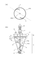
図1中、符号Dで示すものが本発明の洗浄性及びメンテナンス性を向上させた円錐型リボン混合処理装置(以下、円錐型リボン混合処理装置Dと称する。)であり、この装置は、逆円錐状の処理槽1内に具えられた回転翼3によって被処理物Wの混合、破砕、乾燥、殺菌、冷却の各処理のいずれか一つまたは複数の処理を行うための装置である。
[Cone type ribbon mixing processing equipment with ribbon wing type counter balancer]
In FIG. 1, what is indicated by a symbol D is a conical ribbon mixing processing apparatus (hereinafter referred to as a conical ribbon mixing processing apparatus D) having improved cleaning properties and maintainability according to the present invention. It is an apparatus for performing any one or a plurality of processes of mixing, crushing, drying, sterilization, and cooling of the workpiece W by the
まず前記処理槽1は、適宜の金属素材を逆円錐形に形成して成る円錐部1Aと、この円錐部1Aの上方に連結された円筒部1Bとにより処理槽本体10が形成され、円筒部1Bの上部開口部が天板11によって塞がれて、処理槽1の内部空間を処理空間として構成されたものである。
また前記天板11に対しては投入口12が形成され、更に処理槽1の下部には排出口13が形成される。
First, in the
An
更に前記天板11上には、モータM及び減速機2が具えられ、減速機2の出力軸は、処理槽1内に配される回転翼3の回転軸30に連結される。
また前記回転翼3は、回転軸30の軸方向に沿って複数の支持バー31が固定され、この支持バー31の端部に対して、幅細のリボン翼32が先細り螺旋状に取り付けられて成るものである。
Further, a motor M and a
The
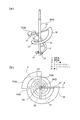
また前記円筒部1B内には、前記リボン翼32によって円錐部1Aの内壁に沿って上昇してきた処理物Wを、処理槽1の中央付近に移動させるとともに処理槽1下部に落下させる渦流ブレーカ6が具えられるものであり、この実施例では一例として図2(a)の平面図に示すように回転軸30を中心として対称の位置の二カ所に具えるようにした。
Also, in the
そして平面視における回転翼3の重心G0の位置は、回転軸30の中心と重なるようになるのが理想的であるが、現実には幅寸法や周長が上下方向で異なるといったリボン翼32の複雑な形状と、リボン翼32を支える支持バー31とに起因して、図3(b) に示すように回転軸30の中心と重なることなく大きくズレてしまう。
そこで本発明では、このようなズレを補正するようなカウンターバランサ5が具えられるものである。ここでカウンターバランサ5が具えられる前の回転翼3の重心をG0とし、カウンターバランサ5の重心をG1とし、更にカウンターバランサ5が具えられた状態の回転翼3の重心をG2として説明を行うものとする。
この実施例ではリボン翼タイプのカウンターバランサ51が採用されるものであり、このカウンターバランサ51を回転軸30に接続するための支持バー53も実質的にカウンターバランサ5の構成要素となる。
このタイプのカウンターバランサ51は、図3(b)に示すように平面視において、回転軸30の中心を中心点として、回転翼3の重心G0から180°の方向の点と回転翼3の重心G0とを結んだ線を基準ラインLとし、この基準ラインLから左右60°の範囲内にカウンタバランサ51の重心G1が位置するように設けられるものである。この結果、回転翼3の重心G0は回転軸30のほぼ中心に位置する重心G2として補正されることとなる。この範囲にカウンタバランサ51の重心G1を位置させることにより回転が安定し、更に回転が安定することにより被処理物Wの流動が安定するために 円錐型リボン混合処理装置Dの振動が抑制される。
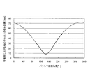
なお図5に示すグラフは、回転軸30の中心点の回りにカウンターバランサ51の位置を変えた場合、重心G2の回転軸30の中心点からの偏心距離の変化を示したものである。このグラフの横軸(バランサ設置角度)は、図3(b)における回転軸30の中心点を基準点とし、更にリボン翼32の最上部を支える支持バー31の中心線を0°方向の基準ラインXとしたときの反時計回りの角度を表しており、カウンターバランサ51の重心G1を反時計回りに位置を変えた場合として表している。
Ideally, the position of the center of gravity G0 of the
Therefore, in the present invention, a
In this embodiment, a ribbon wing
As shown in FIG. 3B, this type of
Note that the graph shown in FIG. 5 shows a change in the eccentric distance from the center point of the
またこのようなリボン翼タイプのカウンターバランサ51は、同じ高さに位置するリボン翼5の0.3〜1.2倍の幅となるように設定され、且つその長さは一周以内(一巻き分すなわち360°以内)に設定される。図3(b)に示した実施例は、リボン翼タイプのカウンターバランサ51を1/4周(90°)としたものである。なお、リボン翼タイプのカウンターバランサ51の幅が、同じ高さに位置するリボン翼5の0.3倍より狭い場合、重心バランスを確保するための設計が困難であったり、被処理物Wを対称的に流動させる作用が弱くなってしまう。またリボン翼タイプのカウンターバランサ51の幅が、同じ高さに位置するリボン翼5の1.2倍より広い場合、被処理物Wの付着や残留が増えて洗浄性やメンテナンス性を損なったり、これらの作業をする上での目視確認の妨げになり易く、好ましくない。
The ribbon blade
なお図8に示した既存の一条タイプの回転翼3′の場合、重心G0を回転軸30′の中心に近づけるために、リボン翼32′の幅寸法等を変更することがあったが、本発明によればこのような改変は不要となり、リボン翼32を被処理物Wの流動に好適な形状のままとすることができる。
In the case of the existing single-strip
本発明の円錐型リボン混合処理装置Dは一例として上述のように構成されるものであり、以下、この装置の運転状態について説明し、続いてメンテナンス作業の態様について説明する。
まず始めにモータMを起動して回転翼3を回転させながら、被処理物Wを投入口12から処理槽1内に投入するものであり、被処理物Wは螺旋状のリボン翼32に案内されながら処理槽本体10の内壁に沿って上昇することとなる。
このとき本発明によれば、平面視において回転翼3の重心G0が回転軸30の中心に位置する重心G2として補正されるため、回転軸30を上部のみでの片持ちとしながらも、安定した回転状態を得ることができ、回転翼3を高速で回転させることが可能となる。このため低速回転させた場合に発生してしまう、被処理物Wが撹拌されずに回転翼3とともに回ってしまういわゆる共回りや、混合ムラ、乾燥ムラ、ダマの発生等を回避することが可能となる。
The conical ribbon mixing treatment apparatus D of the present invention is configured as described above as an example, and hereinafter, the operation state of this apparatus will be described, and then the mode of maintenance work will be described.
First, the workpiece W is introduced into the
At this time, according to the present invention, since the center of gravity G0 of the
またリボン翼32に案内されながら処理槽本体10の内壁に沿って上昇した被処理物Wは、渦流ブレーカ6によって案内されて、処理槽1の中央付近に移動するとともに処理槽1下部に落下する。渦流ブレーカ6は、処理槽本体10内での被処理物Wの循環を促進させるための部材であるが、被処理物Wが処理槽本体10内面に流動しながら接触する際や渦流ブレーカ6に接触する際に衝撃を生じてしまう。
しかしながら本発明の円錐リボン型混合処理装置Dにあっては、処理槽1内の上部に位置する被処理物Wは、リボン翼タイプのカウンターバランサ51にも案内されて回転軸30を中心として対称的に流動することとなり、やがて渦流ブレーカ6と接触することとなる。このため被処理物Wは回転軸30や処理槽本体10内面に対して対称的な流動を生じ、また回転軸30に対して対称の位置の二カ所に具えられる渦流ブレーカ6に同時に被処理物Wが接触するため、その衝撃はほぼ相殺されることとなり、回転翼3の回転を安定したものとし、円錐リボン型混合処理装置Dの振動を抑制することができる。
In addition, the workpiece W that has risen along the inner wall of the
However, in the conical ribbon type mixing processing apparatus D of the present invention, the workpiece W positioned in the upper part in the
そして粘度の高い処理物Wがリボン翼32及び支持バー31並びにカウンターバランサ51及び支持バー53に付着してしまった場合や、部品交換等のメンテナンスが必要になった場合には、天板11を外して回転翼3を処理槽1から引き抜いた状態で作業が行われることとなるが、本発明の円錐型リボン混合処理装置Dは、リボン翼32が一条であるため、付着物の除去や掃除を要する個所が少なく、作業性に優れている。特に付着物に関してはその量も二条タイプのものと比べて少量で済むこととなり、除去作業が軽減されることとなる。
When the high-viscosity processed product W adheres to the
〔バータイプのカウンターバランサを具えた円錐型リボン混合処理装置〕
次にタイプを異ならせたカウンターバランサ5について説明する。
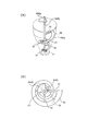
図4(a)(b)に示すに示す回転翼3は、バータイプのカウンターバランサ52が回転軸30に接続されたものであり、このような回転翼3が処理槽本体10内に具えられることにより、円錐型リボン混合処理装置Dが構成される。そしてカウンタバランサ52は一本のバーのみによって構成されるため、被処理物Wの流動により作用する力が小さい場合は、円錐型リボン混合処理装置Dに生じる振動も軽微であるため安定した運転が行え、図3に示したタイプの回転翼3と比べて付着物をより少量に抑えることができる。
また図4(c)(d)に示すものは、図3(a)(b)に示したリボン翼タイプのカウンターバランサ51の代わりに、丸棒状のカウンターバランサ55が支持バー53により支えられた回転翼3である。このものはバーのみにより構成される図4(a)(b)に示したカウンターバランサ52よりも、回転翼3の回転がよりいっそう安定し、円錐型リボン混合処理装置Dの振動をより一層抑えることができるものである。
なおカウンターバランサ5の設置個所及び本数は、本発明の技術的思想の範囲内において適宜変更することが可能である。
[Conical ribbon mixing equipment with a bar-type counter balancer]
Next, the
4 (a) and 4 (b) is a
4C and 4D, a round bar-shaped
In addition, the installation location and the number of the
〔カウンターバランサを処理槽外部に具えた円錐型リボン混合処理装置〕
また図6はカウンターバランサ5を処理槽1の外部に設けた実施例を示すものであり、回転軸30における処理槽1の外部に位置する部位に、偏心錘状のカウンターバランサ54を具えたものである。
[Conical ribbon mixing treatment equipment with counter balancer outside the treatment tank]
FIG. 6 shows an embodiment in which the
D 円錐型リボン混合処理装置
1 処理槽
1A 円錐部
1B 円筒部
10 処理槽本体
11 天板
12 投入口
13 排出口
2 減速機
3 回転翼
30 回転軸
31 支持バー
32 リボン翼
5 カウンターバランサ
51 カウンターバランサ
52 カウンターバランサ
53 支持バー
54 カウンターバランサ
55 カウンターバランサ
6 渦流ブレーカ
D1′ 円錐型リボン混合処理装置
D2′ 円錐型リボン混合処理装置
G0 重心
G1 重心
G2 重心
L 基準ライン
M モータ
W 被処理物
X 基準ライン
D Conical Ribbon
Claims (5)
Priority Applications (1)
| Application Number | Priority Date | Filing Date | Title |
|---|---|---|---|
| JP2008228725A JP5106324B2 (en) | 2008-09-05 | 2008-09-05 | Conical ribbon mixing device with improved cleaning and maintenance |
Applications Claiming Priority (1)
| Application Number | Priority Date | Filing Date | Title |
|---|---|---|---|
| JP2008228725A JP5106324B2 (en) | 2008-09-05 | 2008-09-05 | Conical ribbon mixing device with improved cleaning and maintenance |
Publications (2)
| Publication Number | Publication Date |
|---|---|
| JP2010058088A true JP2010058088A (en) | 2010-03-18 |
| JP5106324B2 JP5106324B2 (en) | 2012-12-26 |
Family
ID=42185500
Family Applications (1)
| Application Number | Title | Priority Date | Filing Date |
|---|---|---|---|
| JP2008228725A Active JP5106324B2 (en) | 2008-09-05 | 2008-09-05 | Conical ribbon mixing device with improved cleaning and maintenance |
Country Status (1)
| Country | Link |
|---|---|
| JP (1) | JP5106324B2 (en) |
Cited By (6)
| Publication number | Priority date | Publication date | Assignee | Title |
|---|---|---|---|---|
| CN102358495A (en) * | 2011-06-07 | 2012-02-22 | 天津市美好生活科技有限公司 | High-viscosity paste mixing and conveying device and method |
| WO2013141480A1 (en) * | 2012-03-21 | 2013-09-26 | 주식회사 하도 | Impellor of stirring device and stirring device using same |
| CN107486074A (en) * | 2017-07-10 | 2017-12-19 | 云南云天化农业科技股份有限公司 | One kind matches somebody with somebody fertile equipment |
| CN108837766A (en) * | 2018-05-31 | 2018-11-20 | 张传赛 | A kind of integrated blender of food processing cleaning and sterilizing |
| WO2021060550A1 (en) * | 2019-09-27 | 2021-04-01 | 祥二 勝目 | Stirring body and stirring device provided with same |
| US11950614B2 (en) | 2019-10-30 | 2024-04-09 | Sodick Co., Ltd. | Food material powder supply device |
Families Citing this family (1)
| Publication number | Priority date | Publication date | Assignee | Title |
|---|---|---|---|---|
| KR102057014B1 (en) | 2019-11-07 | 2019-12-17 | 가부시키가이샤 오카와라 세이사쿠쇼 | Conical ribbon mixing and drying device comprising tungsten carbide thermal sprayed- layer |
Citations (7)
| Publication number | Priority date | Publication date | Assignee | Title |
|---|---|---|---|---|
| JPS56150424A (en) * | 1980-04-01 | 1981-11-20 | Bhs Bayerische Berg | Mixing mechanism for square tub type mixer |
| JPS62180732A (en) * | 1986-02-04 | 1987-08-08 | Mitsubishi Heavy Ind Ltd | Vertical mixer |
| JPH0360728A (en) * | 1989-07-31 | 1991-03-15 | Hitachi Ltd | Vertical type agitation device |
| JPH11226375A (en) * | 1998-02-12 | 1999-08-24 | Shinkii:Kk | Rocking mechanism for mixing and deaerating device |
| JP2001162152A (en) * | 1999-12-06 | 2001-06-19 | Fiideru Giken:Kk | Mixing vessel |
| JP2001286744A (en) * | 2000-04-04 | 2001-10-16 | Hiromi Suda | Helical blade for stirring |
| JP2003071263A (en) * | 2001-09-06 | 2003-03-11 | Okawara Mfg Co Ltd | Cone-type mixing and drying apparatus |
-
2008
- 2008-09-05 JP JP2008228725A patent/JP5106324B2/en active Active
Patent Citations (7)
| Publication number | Priority date | Publication date | Assignee | Title |
|---|---|---|---|---|
| JPS56150424A (en) * | 1980-04-01 | 1981-11-20 | Bhs Bayerische Berg | Mixing mechanism for square tub type mixer |
| JPS62180732A (en) * | 1986-02-04 | 1987-08-08 | Mitsubishi Heavy Ind Ltd | Vertical mixer |
| JPH0360728A (en) * | 1989-07-31 | 1991-03-15 | Hitachi Ltd | Vertical type agitation device |
| JPH11226375A (en) * | 1998-02-12 | 1999-08-24 | Shinkii:Kk | Rocking mechanism for mixing and deaerating device |
| JP2001162152A (en) * | 1999-12-06 | 2001-06-19 | Fiideru Giken:Kk | Mixing vessel |
| JP2001286744A (en) * | 2000-04-04 | 2001-10-16 | Hiromi Suda | Helical blade for stirring |
| JP2003071263A (en) * | 2001-09-06 | 2003-03-11 | Okawara Mfg Co Ltd | Cone-type mixing and drying apparatus |
Cited By (7)
| Publication number | Priority date | Publication date | Assignee | Title |
|---|---|---|---|---|
| CN102358495A (en) * | 2011-06-07 | 2012-02-22 | 天津市美好生活科技有限公司 | High-viscosity paste mixing and conveying device and method |
| WO2013141480A1 (en) * | 2012-03-21 | 2013-09-26 | 주식회사 하도 | Impellor of stirring device and stirring device using same |
| EP2829316A4 (en) * | 2012-03-21 | 2015-11-18 | Hado Co Ltd | Impellor of stirring device and stirring device using same |
| CN107486074A (en) * | 2017-07-10 | 2017-12-19 | 云南云天化农业科技股份有限公司 | One kind matches somebody with somebody fertile equipment |
| CN108837766A (en) * | 2018-05-31 | 2018-11-20 | 张传赛 | A kind of integrated blender of food processing cleaning and sterilizing |
| WO2021060550A1 (en) * | 2019-09-27 | 2021-04-01 | 祥二 勝目 | Stirring body and stirring device provided with same |
| US11950614B2 (en) | 2019-10-30 | 2024-04-09 | Sodick Co., Ltd. | Food material powder supply device |
Also Published As
| Publication number | Publication date |
|---|---|
| JP5106324B2 (en) | 2012-12-26 |
Similar Documents
| Publication | Publication Date | Title |
|---|---|---|
| JP5106324B2 (en) | Conical ribbon mixing device with improved cleaning and maintenance | |
| JP4741509B2 (en) | Processing unit | |
| JP6725504B2 (en) | Stirrer | |
| JP5739188B2 (en) | Apparatus for homogenizing molten glass and use thereof | |
| US9968896B1 (en) | Stirring device | |
| US20150023134A1 (en) | Agitating bar and agitator comprising the same | |
| JP5062186B2 (en) | Stirring apparatus and stirring method | |
| CA2992188A1 (en) | Stirrer for a stirrer vessel | |
| JP2009029704A5 (en) | ||
| CN105465391A (en) | Rotary valve | |
| JP2007229633A (en) | Cone type ribbon mixing apparatus | |
| CN109803932B (en) | Stirrer and method for manufacturing glass plate | |
| JP2018520956A (en) | Swivel device with sterile air flow | |
| JP6069659B2 (en) | Stirrer | |
| CN204684976U (en) | Screw mixer | |
| US7762717B2 (en) | Device for processing bulk materials | |
| CN109070028B (en) | Stirring device | |
| JP7283346B2 (en) | glass manufacturing method | |
| JP5763247B2 (en) | Food stirrer | |
| TW201603878A (en) | Stirrer structure of organics fermenter | |
| JP3190398U (en) | Coating equipment | |
| JP6756982B2 (en) | Manufacturing method of stirring stirrer and glass plate | |
| JP2017154129A (en) | Crystallization reaction tank and crystallization classifier using the same | |
| JP7337329B2 (en) | Stirrer and Molten Glass Stirrer | |
| JP3822613B2 (en) | Kneading machine |
Legal Events
| Date | Code | Title | Description |
|---|---|---|---|
| A621 | Written request for application examination |
Free format text: JAPANESE INTERMEDIATE CODE: A621 Effective date: 20110812 |
|
| A977 | Report on retrieval |
Free format text: JAPANESE INTERMEDIATE CODE: A971007 Effective date: 20120608 |
|
| A131 | Notification of reasons for refusal |
Free format text: JAPANESE INTERMEDIATE CODE: A131 Effective date: 20120619 |
|
| A521 | Written amendment |
Free format text: JAPANESE INTERMEDIATE CODE: A523 Effective date: 20120820 |
|
| TRDD | Decision of grant or rejection written | ||
| A01 | Written decision to grant a patent or to grant a registration (utility model) |
Free format text: JAPANESE INTERMEDIATE CODE: A01 Effective date: 20120918 |
|
| A01 | Written decision to grant a patent or to grant a registration (utility model) |
Free format text: JAPANESE INTERMEDIATE CODE: A01 |
|
| A61 | First payment of annual fees (during grant procedure) |
Free format text: JAPANESE INTERMEDIATE CODE: A61 Effective date: 20121002 |
|
| R150 | Certificate of patent or registration of utility model |
Ref document number: 5106324 Country of ref document: JP Free format text: JAPANESE INTERMEDIATE CODE: R150 Free format text: JAPANESE INTERMEDIATE CODE: R150 |
|
| FPAY | Renewal fee payment (event date is renewal date of database) |
Free format text: PAYMENT UNTIL: 20151012 Year of fee payment: 3 |
|
| R250 | Receipt of annual fees |
Free format text: JAPANESE INTERMEDIATE CODE: R250 |
|
| R250 | Receipt of annual fees |
Free format text: JAPANESE INTERMEDIATE CODE: R250 |
|
| R250 | Receipt of annual fees |
Free format text: JAPANESE INTERMEDIATE CODE: R250 |