JP2010057544A - Rotor type pitching machine - Google Patents
Rotor type pitching machine Download PDFInfo
- Publication number
- JP2010057544A JP2010057544A JP2008223414A JP2008223414A JP2010057544A JP 2010057544 A JP2010057544 A JP 2010057544A JP 2008223414 A JP2008223414 A JP 2008223414A JP 2008223414 A JP2008223414 A JP 2008223414A JP 2010057544 A JP2010057544 A JP 2010057544A
- Authority
- JP
- Japan
- Prior art keywords
- rotor
- ball
- rotors
- pitching machine
- pitching
- Prior art date
- Legal status (The legal status is an assumption and is not a legal conclusion. Google has not performed a legal analysis and makes no representation as to the accuracy of the status listed.)
- Granted
Links
Images

Landscapes
- Crushing And Pulverization Processes (AREA)
Abstract
Description
本発明は、ローター式ピッチングマシーンの改良に関するものであって、主として、3つの投球用ローターをY型に配置し、3つのローターによりボールを挟持し、ローターの回転力にて、ボールを投球するピッチングマシーンにおいて、3つのローターのうち、少なくとも一つのローターである中央下ローターにクッション装置を備えたことを特徴とする3ローター式ピッチングマシーンを提供するものである。 The present invention relates to an improvement of a rotor-type pitching machine, and mainly includes three throwing rotors arranged in a Y shape, a ball is sandwiched between the three rotors, and the ball is thrown by the rotational force of the rotor. In the pitching machine, a three-rotor pitching machine is provided in which a cushion device is provided in a lower central rotor, which is at least one of the three rotors.
ローターの回転力でボールを投球する際に、安定したコントロールを求めるため、3つのローターでボールを挟持して、ボールを投球する3ローター式ピッチングマシーンが利用されていた。 In order to obtain stable control when throwing a ball with the rotational force of a rotor, a three-rotor pitching machine in which the ball is held by three rotors to throw the ball has been used.
この3ローター式ピッチングマシーンは、特許文献1に示されるように、すでに自由実施技術として存在していた。その後、3ローター式ピッチングマシーンには、特許文献2に見られるような映像との組み合わせの技術や、特許文献3に見られるような特殊制御方法を採用した技術が提案されてきた。
This three-rotor pitching machine has already existed as a free implementation technique as disclosed in
しかし、ボールを投球する際に3つのローターで挟持する場合、ボールをローターで圧縮することで安定した投球が可能となるが、この圧縮によりボールの傷みも早くなってしまう。この点に関する改良は特許文献1乃至3でも行われていなかった。
However, when the ball is thrown between the three rotors, the ball is compressed by the rotor, so that stable pitching is possible, but this damage also speeds up the ball damage. No improvement in this regard has been made in
本発明は、ローターでボールを圧縮して保持する際に、過度な保持を避け、ボールの耐久性を上げることを目的に提案されたピッチングマシーンである。 The present invention is a pitching machine proposed for the purpose of avoiding excessive holding and increasing the durability of the ball when the ball is compressed and held by a rotor.
第1の発明は、上記課題を解決するため、ローターにてボールを挟持し、ローターの外方向に向かう回転力でボールを投球するピッチングマシーンにおいて、いずれか一つのローターのローター支持部材とマシーン本体の間に緩衝手段を設けたことを特徴とするピッチングマシーンを提供する。 In order to solve the above-mentioned problems, a first invention is a pitching machine in which a ball is held by a rotor and a ball is thrown with a rotational force directed outward of the rotor, and the rotor support member and the machine body of any one of the rotors A pitching machine characterized in that a buffer means is provided between the two.
第2の発明は、3つの投球用ローターをY型に配置し、3つのローターによりボールを挟持し、ローターの外方向に向かう回転力にて、ボールを投球するピッチングマシーンにおいて、3つのローターのうち下方に位置するローターの支持部材に下方に向かって逃げ構造を有する緩衝手段を設けたピッチングマシーンを提供する。 In the second invention, in a pitching machine in which three throwing rotors are arranged in a Y shape, a ball is sandwiched between the three rotors, and the ball is thrown by a rotational force directed outward of the rotor, A pitching machine is provided in which a cushioning means having a relief structure is provided on a support member of a rotor located below.
第1の発明は、いずれか一つのローターのローター支持部材とマシーン本体の間に緩衝手段を設けたものであるので、ボール挿入空間7でのボールの圧縮が強くなりすぎた場合に、緩衝手段を備えたローターが若干退避することになり、ボールに対する過度の圧縮を防げ、ボールの耐久力を上げることが可能となった。 In the first aspect of the present invention, the buffer means is provided between the rotor support member of any one of the rotors and the machine body. Therefore, when the compression of the ball in the ball insertion space 7 becomes too strong, the buffer means is provided. The rotor provided with a slight retraction causes the ball to be prevented from being excessively compressed, and the durability of the ball can be increased.
更に、第2の発明の効果ではあるが、3つの投球用ローターをY型に配置したピッチングマシーンにおいて、3つのローターのうち下方に位置するローターの支持部材に下方に向かって逃げ構造を有する緩衝手段を設けたものであるので、簡単な構造で、緩衝手段の設置ができる上、下方への逃げであるためボールコントロールの制御にも複雑な対応をしなくてもよいものとなった。更に、コントロール性能も上がることが投球の実験結果からも判明している。 Further, in the pitching machine in which the three throwing rotors are arranged in the Y shape, the buffer having a relief structure downward on the support member of the rotor located below among the three rotors is an effect of the second invention. Since the means is provided, the buffer means can be installed with a simple structure, and since it is a downward escape, it is not necessary to make a complicated response to the control of the ball control. Furthermore, it has been found from the results of throwing experiments that the control performance is also improved.
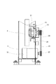
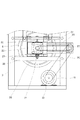
以下、図面に従って、実施例と共に本発明の実施の形態について説明する。図1は、実施例にかかる3ローター式ピッチングマシーンの正面説明図であり、図2は、本発明の特徴的部分となるクッション装置を示す拡大側面説明図であり、図3は、同クッション部材を示す拡大正面説明図である。 Hereinafter, embodiments of the present invention will be described together with examples according to the drawings. FIG. 1 is a front explanatory view of a three-rotor pitching machine according to an embodiment, FIG. 2 is an enlarged side explanatory view showing a cushion device which is a characteristic part of the present invention, and FIG. FIG.
実施例にかかる3ローター式ピッチングマシーン1の概要を説明する。図1に示されるように3ローター式ピッチングマシーン1は、架台2上にローター支持構造体3を設け、ローター支持構造体3に左上ローター4、右上ローター5、中央下ローター6の3個のローター3,4,5をY型に配置し、3個のローター4,5,6の近接する外周面によりボール挿入空間7を形成し、このボール挿入空間7の後方にボール供給用のシューターユニット8を配置したものである。
An outline of the three-
3ローター式ピッチングマシーン1の動作は、ボール挿入空間7にシューターユニット8を介して投球用ボールを供給し、該ボールを3個のローター4,5,6の外周面で挟持し、3個のローター4,5,6の外方向への回転力により、ボールを投球するものである。尚、図中符号11は、投球口である。
The operation of the three-
架台2には移動用の車輪9が前後左右の4カ所に設置されており、移動可能とされている。更に、架台2とローター支持構造体3との間には、図1中詳細は省略されているが、支持構造体3を前後左右に傾斜する角度を調整可能とする角度調整機構10を設けてある。これによりボールの投球の高さや方向が調整可能とされている。
Wheels 9 for movement are installed on the gantry 2 at four locations, front, rear, left, and right, and are movable. Further, an
3個のローター4,5,6は、円盤形のもので外周面は、投球用のボールを圧縮保持(グリップ)しやすい形状と材質で構成されており、ボール外皮より硬質の素材が用いられる。左上ローター4と右上ローター5は、ローター駆動モータ16,17に連結されている。
The three
ローター支持構造体3に固定された固定板12、13には、左右のモータホルダー14,15が固定されている。このモータホルダー14,15が、左上ローター4及び右上ローター5のローター支持部材となる。
The left and
このモータホルダー14,15には、ローター駆動モータ16,17が固定的に設置されている。該ローター駆動モータ16,17の回転軸が左上ローター4及び右上ローター5の回転軸となるローターシャフト(図1中では示されてはいない)と連結されている。実施例では、左上ローター4,右上ローター5には、本発明の特徴となるクッション装置20は装備されていない。
中央下ローター6のローター駆動モータ18も独自に存在するが、ローター駆動モータ18の回転軸19は、中央下ローター6のローターシャフト21に直接連結されたものではない。従って、中央下ローター6の回転力は、ローター駆動モータ18の回転軸19に装着されたモータプーリー22からドライブプーリー23を介して、ローターシャフト21に取り付けられた駆動プーリー24に伝えられることによって付与される。尚、各プーリー22,23,24間の駆動力の伝達は、ベルト25、26によってなされている。
Although the
中央下ローター6のローターシャフト21は、クッション装置20を介してローター支持構造体3に装着されている。クッション装置20が本発明における緩衝手段となる。ローター支持構造体3の中央下ローター6のローターシャフト21の配置付近には、クッション装置20の支持フレーム27が形成されており、支持フレーム27の下フレーム材28にクッション材となるスプリング29を介してクッション装置20は支持フレーム27に対して、上下動可能に装着されている。
The
スプリング29は、投球に対する最適圧縮力をボール挿入空間7に付与可能に設定されており、更に、ナットなどでその調整も可能にされている。このためクッション装置20はローター支持構造体3に対して上下動可能とされている。
The
クッション装置20の中央部にはローターシャフト21が、クッション装置20に対して回転のみが自在で、上下左右方向には移動ができない状態で装着されている。尚、クッション装置20の上方に装着されたボルトは、クッション装置20の上限位置を規制するための上限位置設定ボルト30である。この上限位置設定のための部材は、ボルトである必要はなく、スプリングであってもよい。
A
上記のように、中央下ローター6のローターシャフト21が、クッション装置20とともにローター支持構造体3に対して上下動するものである。他方、ローター支持構造体3に固定された固定板12,13、固定板12,13に固定されたモータホルダー14,15、モータホルダー14,15に固定された左上ローター4、及び右上ローター5は、ローター支持構造体3に対して位置変動の伴わないものであるため、中央下ローター6は、左上ローター4及び右上ローター5に対して下方向に向かって逃げを有していることになる
As described above, the
次に実施例の作用について説明すれば、シューターユニット8よりボールが3つのローター4,5,6の外周面で構成されるボール挿入空間7に送られてくる。ボールはボール挿入空間7で、3個のローター4,5,6の外周面で圧縮保持されながら、各ローター4,5,6の外方向への回転力により投球されるわけであるが、この際、圧縮が強すぎる場合、その圧力により,中央下ローター6が、クッション装置20とともに若干下降し、適正圧縮力にて投球が行われることになる。
Next, the operation of the embodiment will be described. A ball is sent from the
実施例では、3ローター式ピッチングマシーン1の中央下ローター6にクッション装置20を持たせているが、他のローターの1カ所にクッション装置を持たせてもよく、更に、3ローター式ピッチングマシーン1以外のローター式ピッチングマシーンであっても、ローターの少なくとも1カ所にクッション装置を持たせることができるものである。
In the embodiment, the
1・・・3ローター式ピッチングマシーン
2・・・架台
3・・・ローター支持構造体
4・・・左上ローター
5・・・右上ローター
6・・・中央下ローター
7・・・ボール挿入空間
8・・・シューターユニット
9・・・車輪
10・・角度調整機構
11・・・投球口
12,13・・・固定板
14,15・・・モータホルダー
16,17,18・・・ローター駆動モータ
19・・・回転軸
20・・・クッション装置
21・・・ローターシャフト
22・・・モータプーリー
23・・・ドライブプーリー
24・・・駆動プーリー
25,26・・・ベルト
27・・・支持フレーム
28・・・下フレーム材
29・・・スプリング
30・・・上限位置設定ボルト
DESCRIPTION OF
Claims (2)
In a pitching machine in which a ball is pinched by a rotor and a ball is thrown with a rotational force directed outward of the rotor, a buffer means is provided between the rotor support member of one of the rotors and the machine body. Pitching machine.
Priority Applications (1)
| Application Number | Priority Date | Filing Date | Title |
|---|---|---|---|
| JP2008223414A JP5041245B2 (en) | 2008-09-01 | 2008-09-01 | Rotor type pitching machine |
Applications Claiming Priority (1)
| Application Number | Priority Date | Filing Date | Title |
|---|---|---|---|
| JP2008223414A JP5041245B2 (en) | 2008-09-01 | 2008-09-01 | Rotor type pitching machine |
Publications (2)
| Publication Number | Publication Date |
|---|---|
| JP2010057544A true JP2010057544A (en) | 2010-03-18 |
| JP5041245B2 JP5041245B2 (en) | 2012-10-03 |
Family
ID=42185057
Family Applications (1)
| Application Number | Title | Priority Date | Filing Date |
|---|---|---|---|
| JP2008223414A Active JP5041245B2 (en) | 2008-09-01 | 2008-09-01 | Rotor type pitching machine |
Country Status (1)
| Country | Link |
|---|---|
| JP (1) | JP5041245B2 (en) |
Citations (3)
| Publication number | Priority date | Publication date | Assignee | Title |
|---|---|---|---|---|
| JPS6245062U (en) * | 1985-09-06 | 1987-03-18 | ||
| JPH08150236A (en) * | 1994-11-30 | 1996-06-11 | Mitsubishi Heavy Ind Ltd | Ball shooting device |
| JP2006061231A (en) * | 2004-08-25 | 2006-03-09 | Kanazawa Univ | Pitching machine and breaking ball control method therefor |
-
2008
- 2008-09-01 JP JP2008223414A patent/JP5041245B2/en active Active
Patent Citations (3)
| Publication number | Priority date | Publication date | Assignee | Title |
|---|---|---|---|---|
| JPS6245062U (en) * | 1985-09-06 | 1987-03-18 | ||
| JPH08150236A (en) * | 1994-11-30 | 1996-06-11 | Mitsubishi Heavy Ind Ltd | Ball shooting device |
| JP2006061231A (en) * | 2004-08-25 | 2006-03-09 | Kanazawa Univ | Pitching machine and breaking ball control method therefor |
Also Published As
| Publication number | Publication date |
|---|---|
| JP5041245B2 (en) | 2012-10-03 |
Similar Documents
| Publication | Publication Date | Title |
|---|---|---|
| JP2007032654A5 (en) | ||
| JP2005510348A (en) | Horizontal mill | |
| RU2012154659A (en) | GRINDER MACHINE | |
| JP2008302921A5 (en) | ||
| JP3634995B2 (en) | Sanda | |
| JP2008302921A6 (en) | Vehicle seat | |
| CN112658893A (en) | Polishing device | |
| CN205821966U (en) | A kind of milling machine | |
| JP2010057544A (en) | Rotor type pitching machine | |
| JP2016044485A (en) | Corrective grinder for rail | |
| CN106824761A (en) | One kind vibration stone remover | |
| JP2006239809A (en) | Both-sided polishing device | |
| KR20030051133A (en) | A machine for polishing pipes | |
| CN109648423B (en) | Edging grinder connecting device for stone edging machine | |
| CN108723913A (en) | A kind of construction wall polishing device | |
| JP2011115895A (en) | Buff polishing device | |
| CN206896675U (en) | Running platform of running machine device | |
| JP4529865B2 (en) | Band saw board | |
| JP2012218481A (en) | Seat back support device | |
| CN217453445U (en) | Supporting structure | |
| CN202668290U (en) | Bouncing correction grinding machine of motor shaft impeller fixing station | |
| CN218778427U (en) | Shock attenuation stable form paper guide | |
| KR20100006337U (en) | Grinder with twin grinding heads | |
| CN215347260U (en) | Children fever heat dissipation helmet | |
| KR102315092B1 (en) | Roll grinder tilting device |
Legal Events
| Date | Code | Title | Description |
|---|---|---|---|
| A621 | Written request for application examination |
Free format text: JAPANESE INTERMEDIATE CODE: A621 Effective date: 20100609 |
|
| A977 | Report on retrieval |
Free format text: JAPANESE INTERMEDIATE CODE: A971007 Effective date: 20120126 |
|
| A131 | Notification of reasons for refusal |
Free format text: JAPANESE INTERMEDIATE CODE: A131 Effective date: 20120207 |
|
| A521 | Written amendment |
Free format text: JAPANESE INTERMEDIATE CODE: A523 Effective date: 20120405 |
|
| TRDD | Decision of grant or rejection written | ||
| A01 | Written decision to grant a patent or to grant a registration (utility model) |
Free format text: JAPANESE INTERMEDIATE CODE: A01 Effective date: 20120612 |
|
| A01 | Written decision to grant a patent or to grant a registration (utility model) |
Free format text: JAPANESE INTERMEDIATE CODE: A01 |
|
| A61 | First payment of annual fees (during grant procedure) |
Free format text: JAPANESE INTERMEDIATE CODE: A61 Effective date: 20120627 |
|
| R150 | Certificate of patent or registration of utility model |
Ref document number: 5041245 Country of ref document: JP Free format text: JAPANESE INTERMEDIATE CODE: R150 Free format text: JAPANESE INTERMEDIATE CODE: R150 |
|
| FPAY | Renewal fee payment (event date is renewal date of database) |
Free format text: PAYMENT UNTIL: 20150720 Year of fee payment: 3 |
|
| R250 | Receipt of annual fees |
Free format text: JAPANESE INTERMEDIATE CODE: R250 |
|
| R250 | Receipt of annual fees |
Free format text: JAPANESE INTERMEDIATE CODE: R250 |
|
| S111 | Request for change of ownership or part of ownership |
Free format text: JAPANESE INTERMEDIATE CODE: R313113 |
|
| R250 | Receipt of annual fees |
Free format text: JAPANESE INTERMEDIATE CODE: R250 |
|
| R350 | Written notification of registration of transfer |
Free format text: JAPANESE INTERMEDIATE CODE: R350 |
|
| R250 | Receipt of annual fees |
Free format text: JAPANESE INTERMEDIATE CODE: R250 |
|
| R250 | Receipt of annual fees |
Free format text: JAPANESE INTERMEDIATE CODE: R250 |
|
| S531 | Written request for registration of change of domicile |
Free format text: JAPANESE INTERMEDIATE CODE: R313531 |
|
| R350 | Written notification of registration of transfer |
Free format text: JAPANESE INTERMEDIATE CODE: R350 |
|
| R250 | Receipt of annual fees |
Free format text: JAPANESE INTERMEDIATE CODE: R250 |
|
| R250 | Receipt of annual fees |
Free format text: JAPANESE INTERMEDIATE CODE: R250 |
|
| R250 | Receipt of annual fees |
Free format text: JAPANESE INTERMEDIATE CODE: R250 |