JP2010057047A - Management sensor system and sensor shelf - Google Patents
Management sensor system and sensor shelf Download PDFInfo
- Publication number
- JP2010057047A JP2010057047A JP2008221587A JP2008221587A JP2010057047A JP 2010057047 A JP2010057047 A JP 2010057047A JP 2008221587 A JP2008221587 A JP 2008221587A JP 2008221587 A JP2008221587 A JP 2008221587A JP 2010057047 A JP2010057047 A JP 2010057047A
- Authority
- JP
- Japan
- Prior art keywords
- sensor
- coil
- shelf
- magnetic field
- management
- Prior art date
- Legal status (The legal status is an assumption and is not a legal conclusion. Google has not performed a legal analysis and makes no representation as to the accuracy of the status listed.)
- Granted
Links
- 229910052751 metal Inorganic materials 0.000 claims abstract description 181
- 239000002184 metal Substances 0.000 claims abstract description 181
- 230000035945 sensitivity Effects 0.000 claims abstract description 38
- 239000004033 plastic Substances 0.000 claims description 37
- 239000000696 magnetic material Substances 0.000 claims description 30
- 238000004891 communication Methods 0.000 claims description 24
- 230000001965 increasing effect Effects 0.000 claims description 20
- 230000008878 coupling Effects 0.000 claims description 19
- 238000010168 coupling process Methods 0.000 claims description 19
- 238000005859 coupling reaction Methods 0.000 claims description 19
- 238000004804 winding Methods 0.000 claims description 19
- 238000005728 strengthening Methods 0.000 claims description 5
- 210000000078 claw Anatomy 0.000 claims description 4
- 238000013459 approach Methods 0.000 claims description 3
- 230000004323 axial length Effects 0.000 claims 1
- 239000000126 substance Substances 0.000 abstract 3
- XEEYBQQBJWHFJM-UHFFFAOYSA-N Iron Chemical compound [Fe] XEEYBQQBJWHFJM-UHFFFAOYSA-N 0.000 description 34
- 229910052742 iron Inorganic materials 0.000 description 17
- 239000003990 capacitor Substances 0.000 description 15
- 238000000034 method Methods 0.000 description 14
- 230000004907 flux Effects 0.000 description 13
- 238000010586 diagram Methods 0.000 description 12
- 230000006698 induction Effects 0.000 description 12
- 230000000694 effects Effects 0.000 description 9
- 230000035699 permeability Effects 0.000 description 9
- 238000009826 distribution Methods 0.000 description 8
- 238000003860 storage Methods 0.000 description 6
- 230000007423 decrease Effects 0.000 description 5
- 239000002985 plastic film Substances 0.000 description 5
- 239000000758 substrate Substances 0.000 description 5
- 229910052782 aluminium Inorganic materials 0.000 description 4
- XAGFODPZIPBFFR-UHFFFAOYSA-N aluminium Chemical compound [Al] XAGFODPZIPBFFR-UHFFFAOYSA-N 0.000 description 4
- 230000001360 synchronised effect Effects 0.000 description 3
- 239000000853 adhesive Substances 0.000 description 2
- 230000001070 adhesive effect Effects 0.000 description 2
- 238000005452 bending Methods 0.000 description 2
- 230000008859 change Effects 0.000 description 2
- 230000001939 inductive effect Effects 0.000 description 2
- 239000012212 insulator Substances 0.000 description 2
- 238000004904 shortening Methods 0.000 description 2
- 230000007480 spreading Effects 0.000 description 2
- 238000003892 spreading Methods 0.000 description 2
- 239000013589 supplement Substances 0.000 description 2
- HIZCTWCPHWUPFU-UHFFFAOYSA-N Glycerol tribenzoate Chemical compound C=1C=CC=CC=1C(=O)OCC(OC(=O)C=1C=CC=CC=1)COC(=O)C1=CC=CC=C1 HIZCTWCPHWUPFU-UHFFFAOYSA-N 0.000 description 1
- 229910000831 Steel Inorganic materials 0.000 description 1
- 230000004308 accommodation Effects 0.000 description 1
- 230000002411 adverse Effects 0.000 description 1
- 230000008901 benefit Effects 0.000 description 1
- 239000004020 conductor Substances 0.000 description 1
- 230000001934 delay Effects 0.000 description 1
- 238000006073 displacement reaction Methods 0.000 description 1
- 230000002708 enhancing effect Effects 0.000 description 1
- 230000005284 excitation Effects 0.000 description 1
- 239000011888 foil Substances 0.000 description 1
- 230000006870 function Effects 0.000 description 1
- 230000006872 improvement Effects 0.000 description 1
- 238000009434 installation Methods 0.000 description 1
- 239000011810 insulating material Substances 0.000 description 1
- 238000009413 insulation Methods 0.000 description 1
- 239000000463 material Substances 0.000 description 1
- 229910052755 nonmetal Inorganic materials 0.000 description 1
- 238000005192 partition Methods 0.000 description 1
- 229920006255 plastic film Polymers 0.000 description 1
- 239000004417 polycarbonate Substances 0.000 description 1
- 229920000515 polycarbonate Polymers 0.000 description 1
- 230000009467 reduction Effects 0.000 description 1
- 238000000926 separation method Methods 0.000 description 1
- 229910001220 stainless steel Inorganic materials 0.000 description 1
- 239000010935 stainless steel Substances 0.000 description 1
- 239000010959 steel Substances 0.000 description 1
- 239000004575 stone Substances 0.000 description 1
- 101150075118 sub1 gene Proteins 0.000 description 1
- 229910000859 α-Fe Inorganic materials 0.000 description 1
Images


Abstract
Description
本発明は、管理用センサシステム及びセンサ棚に関するものである。詳しくは、RFID(Radio Frequency IDentification)のセンサを用いて、図書やファイル、書類、記録媒体、銃器等、管理する対象物(ターゲット)となる物品にRFIDのタグを取付け、図書やファイル、書類、記録媒体、銃器等のターゲットをセンサやリーダライタ装置(R/W)を介してPC(パーソナルコンピュータ)で管理する管理用センサシステム及びセンサ棚に関するものである。 The present invention relates to a management sensor system and a sensor shelf. Specifically, using RFID (Radio Frequency IDentification) sensors, RFID tags are attached to articles to be managed (targets) such as books, files, documents, recording media, firearms, books, files, documents, The present invention relates to a management sensor system and a sensor shelf for managing a target such as a recording medium or a firearm by a PC (personal computer) via a sensor or a reader / writer device (R / W).
RFIDのセンサやタグが金属面の近くにあるときは、金属面に誘導電流を発生させ、センサやタグの磁界や電流を打ち消す方向に働くため、これらの通信感度が著しく低下する。 When an RFID sensor or tag is close to a metal surface, an induced current is generated on the metal surface, which works in a direction to cancel the magnetic field or current of the sensor or tag.
例えば、図書館の図書等の管理を行う場合、図書の表紙または裏表紙にあるいはファイルや記録媒体に直かにあるいはケース等の物品(これらを総称して管理するターゲット(対象物)とする)に、平面コイルと平面コイルに接続されたIC(Integrated Circuit)とからなるICタグ(情報記録媒体)を貼りつけ、このコイルを通過する磁界を作るためのセンサを構成するようにしている。しかしながら、センサアンテナ自体であるセンサのコイルの近傍に金属面が存在することにより、センサアンテナから発生する磁界の一部が打ち消されたり、妨害を受けたりしてタグを励振するための充分な磁界が届かなくなる。このため、金属棚上の図書やファイル、記録媒体等のターゲットに貼られたタグの情報が読めなくなる。また、センサとセンサの継ぎ目では水平磁界(後述する実施例において詳しく説明する)が無くなったり、乱れたりして、この部分でも図書等のターゲットに貼り付けたタグの情報が読めない。 For example, when managing library books, etc., on the cover or back cover of books, directly on files or recording media, or on articles such as cases (generally managing them as targets) An IC tag (information recording medium) composed of a planar coil and an IC (Integrated Circuit) connected to the planar coil is attached, and a sensor for creating a magnetic field passing through the coil is configured. However, due to the presence of a metal surface in the vicinity of the sensor coil, which is the sensor antenna itself, a sufficient magnetic field to excite the tag due to cancellation or interference of part of the magnetic field generated from the sensor antenna. Will not reach. For this reason, information on tags attached to targets such as books, files, and recording media on metal shelves cannot be read. In addition, the horizontal magnetic field (described in detail in an embodiment to be described later) disappears or is disturbed at the joint between the sensors, and information on the tag attached to the target such as a book cannot be read even in this portion.
金属棚の影響のみでなく、金属棚を支える両側の側板の金属板によっても図書やファイルや記録媒体等のターゲットに貼られているタグのコイル(以下、タグコイル)の磁界が打ち消されたり、コイルが金属面により遮蔽されたりして、近傍にある図書等のターゲットに貼り付けたタグの情報を読むことができなくなる。 Not only the influence of the metal shelves, but also the metal plates on both side plates that support the metal shelves cancel out the magnetic field of the coil of the tag (hereinafter referred to as tag coil) that is affixed to the target of books, files, recording media, etc. May be shielded by a metal surface, making it impossible to read tag information pasted on a target such as a book in the vicinity.
また前後(前後の位置関係については実施例で説明する図9を参照)に置かれた書棚や管理棚の場合、このセンサ同士の磁界が結合し、干渉を起こすため、ターゲットのタグの情報を読まなくなる。 In addition, in the case of bookshelves and management shelves placed in front and back (refer to FIG. 9 described in the embodiment for the positional relationship between the front and back), the magnetic field between the sensors is coupled and causes interference. I will not read.
このような問題は、上述のように図書等を管理する場合だけでなく、例えば銃器類を管理する場合等、さまざまな物品にタグを取付けて管理する場合に起こり得る。 Such a problem may occur not only when books are managed as described above, but also when tags are attached to various items and managed, for example, when managing firearms.
また、多数のタグが向き合って取付けられる場合、タグ間の相互インダクタンスが増加し、タグ間の干渉が発生するため共振周波数がずれ、タグとセンサ間の通信が行われ難くなり感度が著しく低下する。現在これを避けるため書類等の厚みが20〜25mm以上でないと読めず、この厚さ以上の管理を行うことに限定した使用目的となっている。これらを解決する発明もいくつかなされている(例えば、特許文献1乃至3参照)。
図書棚等の場合、金属棚の上に本が縦に置かれて横並びに重畳される。そして、並べられた本の上側面には鉄やアルミ板等の金属板が用いられ、この上面にセンサアンテナが載せられプラスチック板等によりカバーされ、更にその上にタグを貼りつけた図書やファイル、記録媒体等のターゲットが棚の上に数十冊載せられる構造となる。棚の各段に設置されたセンサは、これらのターゲットに貼り付けられたタグの情報を総て読む必要がある。しかしながらこのような場合には、金属棚の影響により、センサの磁界がターゲットに貼られたタグに充分に届かない。 In the case of a bookshelf or the like, books are placed vertically on a metal shelf and superimposed side by side. Books and files with a metal plate such as iron or aluminum plate used on the upper side of the books, a sensor antenna placed on the upper surface, covered with a plastic plate, etc., and a tag attached to it. In this structure, several tens of targets such as recording media are placed on the shelf. The sensors installed on each level of the shelf need to read all the information on the tags attached to these targets. However, in such a case, the magnetic field of the sensor does not reach the tag attached to the target sufficiently due to the influence of the metal shelf.
そこで、周囲の金属板、特に棚の金属板と両サイドの側板からの影響等をなくし、金属棚に収容された全数の図書や書類、ファイル、プラスチック板等のターゲットに貼られたタグの情報を読み取るようにすることが本発明の目的である。また、CD,DVD等が重ねて戴置されている場合には、これらに貼り付けられたタグの情報を読むことを要求されているが、これもCDやDVD等に貼られたタグのコイルにセンサの磁界が金属面等の影響もあって充分に届かない。また銃器等を管理する場合には、センサにより銃器等の隙間に取付けられた特殊タグの情報を読むことも要求される。 Therefore, the influence of the surrounding metal plates, especially the metal plates of the shelf and the side plates on both sides, is eliminated, and the information on all the books, documents, files, tags attached to the targets such as plastic plates contained in the metal shelf. Is an object of the present invention. In addition, when CDs, DVDs, and the like are placed on top of each other, it is required to read information on tags attached to these, and this is also a coil of tags attached to CDs, DVDs, etc. However, the magnetic field of the sensor does not reach enough due to the influence of metal surface. Also, when managing firearms, etc., it is also required to read information on special tags attached to gaps in the firearms, etc. by sensors.
また、上下段の棚のセンサの干渉、前後の棚の干渉をなくさねばならない。更に、棚の金属支柱や仕切り板の影響をなくさねばならない。 In addition, the interference between the sensors on the upper and lower shelves and the interference between the front and rear shelves must be eliminated. Furthermore, the influence of the metal column and the partition plate on the shelf must be eliminated.
本発明は、このような点に着目してなされたものであり、情報記録媒体が貼り付けられた物品を収容する棚の金属板や金属側板からの影響を軽減でき、金属棚に戴置された物品の情報記録媒体の情報を読み取り管理することができる管理用センサシステム及びセンサ棚を提供することを課題とする。 The present invention has been made paying attention to such points, and can reduce the influence from the metal plate and the metal side plate of the shelf that accommodates the article to which the information recording medium is attached, and is placed on the metal shelf. It is an object of the present invention to provide a management sensor system and a sensor shelf that can read and manage information on an information recording medium of articles.
本発明は下記の構成を備えることにより、上記課題を解決できるものである。 This invention can solve the said subject by providing the following structure.
金属面上に置かれた、
1.断面が四角形状の細長い棒状の磁性体に短辺に沿って(粗巻の状態で)ある程度間隔をおいてコイルを巻き、コイルの軸方向に発生する磁界と平行なコイルの外側や磁性体の外側に発生する横方向の磁界を用いて、このセンサ面と直角な方向でコイルの断面とほぼ平行な方向に置かれた非接触ICカードまたはICタグが貼り付けられた図書や書類やボックスやファイル、記録媒体等の紙やプラスチックに貼り付けたICタグを読み取ったり(書き込んだり)することを特徴とする図書、ファイル、プラスチック板、媒体等のターゲットの管理用センサシステム。
Placed on a metal surface,
1. A coil is wound around an elongated rod-like magnetic body having a square cross section along a short side (in a coarsely wound state) at a certain interval, and the outside of the coil parallel to the magnetic field generated in the axial direction of the coil or the magnetic body Using a lateral magnetic field generated on the outside, a book, document, box, etc. with a non-contact IC card or IC tag affixed in a direction perpendicular to the sensor surface and in a direction substantially parallel to the coil cross section, A sensor system for managing targets of books, files, plastic plates, media, and the like, which reads (writes) IC tags attached to paper or plastic such as files and recording media.
2.細長い棒状の磁性体に棒状のほぼ中心部あるいは片端より両側に向って平列に1本ないしは2本のコイルをほぼ等間隔に短辺に沿って2〜30mmの間隔をおき、粗巻の状態でコイルを巻き、コイルの軸方向に沿って発生するコイルの外側や磁性体の外側で金属面を反対側の磁界を用いて、このセンサ面と直角な方向でコイルの断面とほぼ平行な方向に置かれた非接触式ICカードまたはICタグが貼りつけられた図書や書類やボックスやファイル等の紙やプラスチック板やフィルム媒体等のターゲットが磁界の方向に沿って並べられ、これを読み取ったり書き込んだりすることを特徴とする図書、ファイル媒体等のターゲット管理用センサシステム。 2. Coarse winding of one or two coils in a row in the shape of an elongated rod-shaped magnetic body in parallel with one or two coils from the center or both sides to one side of the rod. Using a magnetic field opposite to the metal surface on the outside of the coil or outside of the magnetic material that is generated along the axial direction of the coil, and in a direction perpendicular to the sensor surface and substantially parallel to the coil cross section Books, documents, boxes, and files such as paper, plastic plates, and film media with non-contact IC cards or IC tags attached to them are lined up along the direction of the magnetic field and read. A sensor system for target management of books, file media, etc. characterized by writing.
3.棚の長さが90cmのとき、センサを収納するケースを45cmの長さに分割し、この分割されたケースの中に1個のセンサを収納する場合と、2個のセンサを収納する場合と、4個のセンサを収納する場合と、8個のセンサを収納する場合とに分け、本や書類等のターゲットが薄くなるに従ってタグの間隔が近づき、従って収容するセンサの数を増することにより、給電電力密度を上昇させることにより感度を増し、タグ間の相互インダクタンスの影響で共振周波数がずれて読み難くなるのを改善することを特徴とする図書、ファイルや媒体等のターゲット管理用センサシステム。 3. When the shelf length is 90 cm, the case for storing the sensor is divided into 45 cm lengths, and one sensor is stored in the divided case, and two sensors are stored. By separating the case of storing four sensors and the case of storing eight sensors, the distance between the tags approaches as the target of a book or document becomes thinner, and therefore the number of sensors to be accommodated increases. A sensor system for target management of books, files, media, etc., which increases sensitivity by increasing the power supply density and improves the difficulty of reading due to the resonance frequency shifting due to the influence of mutual inductance between tags.
4.棚の長さが90cmのとき、センサとこれを収納するケースを45cmの長さに2分割し、この分割されたケースの中に1個のセンサを収納するときは本の厚みが25mm以上のときに用い、本の厚みが25mm以下で10mm前後のときは2個のセンサを収納し、10mm以下で5mm前後の厚みが重なる場合には4個や6個のセンサを収納するようにし電力密度を更に上昇させ、更に薄い場合には6個や8個のセンサ数としセンサ感度を増し、タグとの通信感度を改善することを特徴とする図書、ファイルや媒体等のターゲットの管理用センサシステム。 4). When the shelf length is 90 cm, the sensor and the case for storing the sensor are divided into two parts of 45 cm, and when one sensor is stored in the divided case, the thickness of the book is 25 mm or more. Sometimes, when the thickness of the book is 25 mm or less and around 10 mm, 2 sensors are accommodated. When the thickness is 10 mm or less and the thickness of around 5 mm overlaps, 4 or 6 sensors are accommodated. The sensor system for managing targets such as books, files, and media is characterized by increasing the sensitivity of the sensor by increasing the sensor sensitivity to 6 or 8 if the thickness is further reduced, and improving the communication sensitivity with the tag. .
5.センサコイルは直列であったり、並列であったり、中央給電であったり、片端給電であり、図書やファイル、記録媒体ターゲットの厚みがある程度あり、貼りつけられるタグ間の間隔が25mm以上とれるときは1つのセンサ長が45cm前後でコイルのピッチ間隔が25〜50mmで構成し、上記ターゲットの厚みが10mm前後の薄くタグ間の間隔が10mm前後となる時は単位のセンサ長が22cm前後でコイルのピッチ間隔が10〜30mmで構成し、上記ターゲットの厚みが5mm前後の場合の更に薄くなる場合は、単位の長さが11cm前後でコイルのピッチ間隔が4〜10mmで構成し、上記ターゲットの厚みが2.5mm前後の場合の更に薄いタグ間の干渉が更に大きくなる場合には単位のセンサ長が5.5cm前後でコイルのピッチ間隔が2〜5mmで構成し、更に上記ターゲットの厚みが1〜2mm前後の場合には単位のセンサ長が2〜3cm前後でコイルのピッチ間隔が1〜3mmで構成することを特徴とする図書、ファイル、媒体等のターゲット管理用センサシステム。 5. When the sensor coil is in series, parallel, central feeding, single-sided feeding, books, files, and recording medium targets have a certain thickness, and the interval between tags to be pasted is 25 mm or more When one sensor length is about 45 cm and the coil pitch interval is 25 to 50 mm, the thickness of the target is about 10 mm and the distance between tags is about 10 mm, the unit sensor length is about 22 cm. When the pitch interval is 10 to 30 mm and the thickness of the target is further reduced to about 5 mm, the unit length is about 11 cm and the coil pitch interval is 4 to 10 mm. The thickness of the target If the interference between the thinner tags becomes larger when the thickness is about 2.5 mm, the unit sensor length is about 5.5 cm. The pitch interval is 2 to 5 mm, and when the thickness of the target is about 1 to 2 mm, the unit sensor length is about 2 to 3 cm and the coil pitch interval is 1 to 3 mm. Sensor system for target management of books, files, media, etc.
6.断面が楕円のような曲線の描く偏平の板あるいは4角状の細長い棒状の磁性体において、幅が15〜100mmで高さが0.5〜30mmの大きさであり、この磁性体に直接あるいはプラスチックシートを介して線状あるいは帯状のコイルを間隔を1mm〜30mmあけて巻くことを特徴とする図書、ファイル、媒体等のターゲットの管理用センサシステム。 6). A flat plate or quadrilateral elongated rod-shaped magnetic body having an elliptical cross section, the width is 15 to 100 mm and the height is 0.5 to 30 mm. A sensor system for managing targets of books, files, media, etc., characterized by winding a linear or belt-like coil with a gap of 1 to 30 mm through a plastic sheet.
7.二個以上並ぶセンサにおいて、隣のセンサの磁界で感度が零となる地点のタグを読めるように隣のセンサで補うことを特徴とする図書、ファイル、媒体等のターゲットの管理用センサシステム。 7). A sensor system for managing targets of books, files, media, etc., in which two or more sensors are arranged so that the tag of the point where sensitivity becomes zero can be read by the magnetic field of the adjacent sensor.
8.二個以上並ぶセンサにおいて、隣とのセンサ間に間隔を置き、ほぼ同一の幅の長さ方向に1〜4cmの長さが短い磁性体にコイルを巻き、このインダクタンスLと共振がとれるコンデンサCを備えることにより、水平の外部磁界が弱くなったり逆相となったりしないように補助センサを設け、磁界が同相あるいは90°位相となり強くなるようにしたことを特徴とする図書、ファイル、媒体等のターゲットの管理用センサシステム。 8). In a sensor in which two or more sensors are lined up, a coil is wound around a magnetic material having a short length of 1 to 4 cm in the length direction of substantially the same width, and a capacitor C that can resonate with this inductance L. By providing an auxiliary sensor so that the horizontal external magnetic field does not become weaker or out of phase, the books, files, media, etc. are characterized in that the magnetic field becomes stronger in phase or 90 ° phase. Sensor system for the management of targets.
9.コイルを巻かれた0.5mm〜30mmの厚みの四角の棒状の磁性体に発生する磁界並びにこれにより励磁される外部の磁界が直接側板の金属面により発生する誘導電流により打ち消されないように側面等の金属面に沿って磁性体板を沿わせて磁路を作り、コイル電流により発生するコイルの軸方向の磁界が金属面と平行な磁路を通りUターンし、本や紙、プラスチックに取付けられたタグを励振できるようにしたことを特徴とする図書、ファイル、媒体等のターゲットの管理用センサシステム。 9. Side surfaces so that a magnetic field generated in a square rod-shaped magnetic body having a thickness of 0.5 mm to 30 mm wound with a coil and an external magnetic field excited thereby are not canceled by an induced current generated by the metal surface of the side plate. A magnetic path is made by placing a magnetic plate along a metal surface, etc., and the magnetic field in the axial direction of the coil generated by the coil current makes a U-turn through the magnetic path parallel to the metal surface and is attached to a book, paper, or plastic A sensor system for managing targets of books, files, media, etc., characterized in that the tag can be excited.
10.上記9において、金属面に沿う磁性体板や磁性体ブロックにLCによる共振器を取付け、タグを励振する磁界を強くし、読み取りが改善されることを特徴とする図書、ファイル、媒体、銃器等に取付けられたターゲット管理用センサシステム。 10. 9. Books, files, media, firearms, etc. characterized in that LC resonators are attached to magnetic plates and magnetic blocks along the metal surface, the magnetic field exciting the tag is strengthened, and reading is improved Sensor system for target management attached to the.
11.同一平面内に前後に備えられた棚において、前と後の棚に納められたセンサ同士の磁界による結合により発生する干渉を押えるため、棚を支える支柱を利用して前後のセンサの間に鉄板やアルミ板やステンレス板等の金属板を遮蔽板として用いることを特徴とする図書、ファイル、媒体等のターゲット管理用センサシステム。 11. In order to suppress interference caused by the coupling between the sensors stored in the front and rear shelves in the same plane in the same plane, the steel plate is used between the front and rear sensors using a support column that supports the shelves. A sensor system for target management of books, files, media, etc., characterized by using a metal plate such as aluminum plate or stainless steel plate as a shielding plate.
12.金属棚の側板の一部をプラスチックとすることにより連続して棚をつなげられるようにしたことを特徴とする図書、ファイル管理用センサシステム。 12 A book and file management sensor system characterized in that a part of a side plate of a metal shelf is made of plastic so that shelves can be connected continuously.
13.棚を支える支柱に側板を支える金具の穴以外にケーブルの通る穴を設け、支柱の中にケーブルを通すことにより、ケーブルの束が棚上の媒体の邪魔にならないようにすることを特徴とする図書、ファイル、媒体等のターゲット管理用センサシステム。 13. In addition to the holes for the metal fittings that support the side plates, the cable that supports the shelf is provided with holes for cables to pass through the cable so that the cable bundle does not interfere with the media on the rack. Sensor system for target management of books, files, media, etc.
14.CD,DVD等のケースに磁界の磁路となる磁性体片を取付けることを特徴とする管理用センサシステム。 14 A management sensor system, characterized in that a magnetic material piece serving as a magnetic path of a magnetic field is attached to a case such as a CD or DVD.
15.CD,DVD等のスタンドに磁界の磁路となる磁性体片を取付ける管理用センサシステム。 15. A management sensor system for attaching a magnetic piece to be used as a magnetic path of a magnetic field to a stand such as a CD or DVD.
16.銃器等にタグを取付け、金属面に強いセンサで管理するターゲット管理用センサシステム。 16. Sensor system for target management that attaches tags to firearms and manages them with sensors that are strong on metal surfaces.
すなわち、本発明の技術内容は以下の構成を備えることにより前記課題を解決できた。 That is, the technical contents of the present invention can solve the above-described problems by including the following configuration.
(1)コイルと、前記コイルに接続され物品に関する情報を記憶するICと、を有し、前記物品に貼付される情報記録媒体と、磁性体と、前記磁性体に所定の間隔で巻回されたコイルと、を有し、前記コイルに電流を流して磁界を発生させ前記情報記録媒体のコイルと電磁結合することにより、前記情報記録媒体のICに記憶された前記物品に関する情報の送受信を行う少なくとも1以上のセンサと、前記センサのコイルの軸方向と平行な面を有し、前記センサのコイルが巻回された前記磁性体の一面に接し、前記センサの感度を向上させるための金属部と、を備え、前記センサは、前記センサの磁性体と前記金属部が接する面と反対側の面の外側に発生する該センサのコイルの軸方向に平行な磁界によって、前記情報記録媒体と前記物品に関する情報の送受信を行うことを特徴とする管理用センサシステム。 (1) A coil and an IC that is connected to the coil and stores information about the article, and is wound around the information recording medium attached to the article, the magnetic body, and the magnetic body at a predetermined interval. And transmitting and receiving information related to the article stored in the IC of the information recording medium by causing a current to flow through the coil to generate a magnetic field and electromagnetically coupling with the coil of the information recording medium. A metal part having at least one sensor and a surface parallel to the axial direction of the coil of the sensor, in contact with one surface of the magnetic body around which the sensor coil is wound, and improving the sensitivity of the sensor The sensor comprises the information recording medium and the magnetic field generated by a magnetic field parallel to the axial direction of the coil of the sensor that is generated outside the surface opposite to the surface where the magnetic body of the sensor and the metal portion are in contact with each other. On goods Administrative sensor system characterized by transmitting and receiving information.
(2)前記(1)に記載の管理用センサシステムにおいて、前記センサのコイルは、該センサのコイルの軸方向に物品を並べる場合の前記情報記録媒体が貼付される物品の厚みが厚い場合は、巻回する間隔を広くし、前記物品の厚みが薄い場合は巻回する間隔を狭くすることを特徴とする管理用センサシステム。 (2) In the management sensor system according to (1) above, when the coil of the sensor is thick in the article to which the information recording medium is attached when the article is arranged in the axial direction of the coil of the sensor A sensor system for management characterized in that the winding interval is widened and the winding interval is narrowed when the thickness of the article is thin.
(3)前記(2)に記載の管理用センサシステムにおいて、前記情報記録媒体が貼付される物品の厚みが薄い場合には、前記情報記録媒体間の間隔も近づくのでそれに合せて前記センサのコイルの間隔も狭くし、一個一個の前記情報記録媒体のコイルとの結合がとれ、全部の前記情報記録媒体との交信が可能となるように前記センサのコイルの間隔も狭くし、前記情報記録媒体との交信を強くするようにすることを特徴とする管理用センサシステム。 (3) In the management sensor system according to (2), when the thickness of the article to which the information recording medium is attached is thin, the distance between the information recording media approaches, and accordingly the coil of the sensor The distance between the coils of the sensor is also narrowed so that it can be coupled to each of the coils of the information recording medium and can communicate with all of the information recording media. Sensor system for management characterized by strengthening communication with
(4)前記(1)乃至(3)のいずれかに記載の管理用センサシステムにおいて、2以上の前記センサを並べる場合には、前記2以上のセンサのコイルの軸方向が一致するように配置し、前記情報記録媒体が貼付される物品の厚みが厚い場合には、前記センサのコイルの軸方向の長さを長くしかつ該センサの数を減らし、前記情報記録媒体が貼付される物品の厚みが薄い場合には、前記センサのコイルの軸方向の長さを短くしかつ該センサの数を増やすことを特徴とする管理用センサシステム。 (4) In the management sensor system according to any one of (1) to (3), when two or more sensors are arranged, the coil directions of the two or more sensors are arranged so as to coincide with each other. When the article to which the information recording medium is attached is thick, the length of the sensor coil in the axial direction is increased and the number of the sensors is reduced. When the thickness is small, the length of the sensor coil in the axial direction is shortened and the number of sensors is increased.
(5)前記(1)乃至(4)のいずれか1項に記載の管理用センサシステムにおいて、2以上の前記センサを並べる場合に前記センサと前記センサとの間に配置され、磁性体と、前記磁性体に所定の間隔で巻回された第一のコイルと、前記第一のコイルに接続され前記センサにより発生する磁界を励振するための第一の共振器と、を有する補助手段を備えることを特徴とする管理用センサシステム。 (5) In the management sensor system according to any one of (1) to (4), when two or more sensors are arranged, the sensor is arranged between the sensors, and a magnetic body; Auxiliary means comprising: a first coil wound around the magnetic body at a predetermined interval; and a first resonator connected to the first coil for exciting a magnetic field generated by the sensor. A management sensor system characterized by that.
(6)前記(1)乃至(4)のいずれか1項に記載の管理用センサシステムにおいて、2以上の前記センサを並べる場合に前記センサと前記センサとの間に配置され、磁性体と、前記磁性体に所定の間隔で巻回された第一のコイルと、前記第一のコイルに接続され前記センサにより発生する磁界を励振するための第一の共振器と、前記第一のコイルに直交するように前記磁性体に巻回された第二のコイルと、前記第二のコイルに接続される第二の共振器と、を有する補助手段を備えることを特徴とする管理用センサシステム。 (6) In the management sensor system according to any one of (1) to (4), when two or more sensors are arranged, the sensor is disposed between the sensors, and a magnetic body; A first coil wound around the magnetic body at a predetermined interval; a first resonator connected to the first coil for exciting a magnetic field generated by the sensor; and the first coil A management sensor system comprising auxiliary means having a second coil wound around the magnetic body so as to be orthogonal to each other and a second resonator connected to the second coil.
(7)前記(1)乃至(6)のいずれか1項に記載の管理用センサシステムにおいて、端部に配置される前記センサは、前記センサの磁性体が発生する磁界の磁路を前記センサのコイルの軸方向に平行な磁界へと導くための誘導手段を有することを特徴とする管理用センサシステム。 (7) In the management sensor system according to any one of (1) to (6), the sensor disposed at an end portion includes a magnetic path of a magnetic field generated by a magnetic body of the sensor. A sensor system for management comprising guiding means for guiding the magnetic field parallel to the axial direction of the coil.
(8)前記(7)に記載の管理用センサシステムにおいて、前記誘導手段は、前記センサの磁性体の端部を逆L字形に形成したものであることを特徴とする管理用センサシステム。 (8) The management sensor system according to (7), wherein the guiding means is formed by forming an end portion of a magnetic body of the sensor in an inverted L shape.
(9)前記(1)乃至(8)のいずれか1項に記載の管理用センサシステムにおいて、前記センサのコイルは、前記センサの磁性体の端部から他方の端部に向かって巻回されることを特徴とする管理用センサシステム。 (9) In the management sensor system according to any one of (1) to (8), the coil of the sensor is wound from the end of the magnetic body of the sensor toward the other end. A sensor system for management.
(10)前記(1)乃至(8)のいずれか1項に記載の管理用センサシステムにおいて、前記センサのコイルは、前記センサの磁性体の中央部から両端部に向かって巻回されることを特徴とする管理用センサシステム。 (10) In the management sensor system according to any one of (1) to (8), the coil of the sensor is wound from a central part of the magnetic body of the sensor toward both ends. A sensor system for management.
(11)前記(1)乃至(10)のいずれか1項に記載の管理用センサシステムにおいて、前記センサのコイルは、線状又は帯状であることを特徴とする管理用センサシステム。 (11) The management sensor system according to any one of (1) to (10), wherein the coil of the sensor is linear or strip-shaped.
(12)前記(1)乃至(11)のいずれか1項に記載の管理用センサシステムにおいて、前記センサの磁性体は、断面が平たい矩形又は楕円形であることを特徴とする管理用センサシステム。 (12) The management sensor system according to any one of (1) to (11), wherein the magnetic body of the sensor has a rectangular or elliptical cross section. .
(13)前記(1)乃至(12)のいずれか1項に記載の管理用センサシステムにおいて、前記センサで送受信した前記物品に関する情報を読み取り又は書き込む読取書込装置と、前記センサと前記読取書込装置との整合をとるための整合装置と、前記センサと前記整合装置とを接続する同軸ケーブルと、前記読取書込装置によって読み取り又は書き込んだ前記物品に関する情報を管理するためのコンピュータと、を備えることを特徴とする管理用センサシステム。 (13) In the management sensor system according to any one of (1) to (12), a read / write device that reads or writes information on the article transmitted and received by the sensor, the sensor, and the read book A matching device for matching with a loading device, a coaxial cable connecting the sensor and the matching device, and a computer for managing information about the article read or written by the reading / writing device, A management sensor system comprising:
(14)前記(1)乃至(13)のいずれか1項に記載の管理用センサシステムを備え、前記金属部は、前記少なくとも1以上のセンサを収容するセンサ収容部であり、前記センサ収容部を収納する棚と、前記棚の両端に配置される側板と、前記側板が設置され、前記棚及び該側板を支える2つの支柱と、を備えることを特徴とするセンサ棚。 (14) The management sensor system according to any one of (1) to (13) is provided, wherein the metal portion is a sensor housing portion that houses the at least one sensor, and the sensor housing portion. A sensor shelf comprising: a shelf that stores the side plate; a side plate disposed at both ends of the shelf; and the two columns that are provided with the side plate and support the shelf and the side plate.
(15)前記(14)に記載のセンサ棚において、前記2つの支柱の間に設置される遮蔽手段を備えることを特徴とするセンサ棚。 (15) The sensor shelf according to (14), further comprising shielding means installed between the two columns.
(16)前記(14)又は(15)に記載のセンサ棚において、前記側板は、金属又はプラスチックにより形成されることを特徴とするセンサ棚。 (16) The sensor shelf according to (14) or (15), wherein the side plate is made of metal or plastic.
(17)前記(14)乃至(16)のいずれか1項に記載のセンサ棚において、前記支柱は、前記同軸ケーブルが収容される穴部を有することを特徴とするセンサ棚。 (17) The sensor shelf according to any one of (14) to (16), wherein the support column has a hole portion in which the coaxial cable is accommodated.
(18)前記(15)乃至(17)のいずれか1項に記載のセンサ棚において、前記支柱は、長穴を有し、前記遮蔽手段は、前記長穴に取付けるための爪部を有し、前記側板は、支持部材を有することを特徴とするセンサ棚。 (18) In the sensor shelf according to any one of (15) to (17), the support column has a long hole, and the shielding means has a claw portion for attaching to the long hole. The side plate includes a support member.
(19)前記(14)乃至(18)のいずれか1項に記載のセンサ棚において、前記情報記録媒体を貼付する物品は、CD又はDVDを含む記録媒体であり、前記CD又は前記DVDのプラスチックケースに貼り付けて磁路を作り、前記センサと前記情報記録媒体との結合を強くするための磁性体片を備えることを特徴とするセンサ棚。 (19) In the sensor shelf according to any one of (14) to (18), the article to which the information recording medium is attached is a recording medium including a CD or a DVD, and the plastic of the CD or the DVD A sensor shelf, comprising a magnetic piece for attaching to a case to form a magnetic path and strengthening the coupling between the sensor and the information recording medium.
(20)前記(14)乃至(18)のいずれか1項に記載のセンサ棚において、前記情報記録媒体を貼付する物品は、CD又はDVDを含む記録媒体であり、前記CD又は前記DVDを収納するためのホルダに貼り付けて磁路を作り、前記センサと前記情報記録媒体との結合を強くするための磁性体片を備えることを特徴とするセンサ棚。 (20) In the sensor shelf according to any one of (14) to (18), the article to which the information recording medium is attached is a recording medium including a CD or a DVD, and stores the CD or the DVD. A sensor shelf comprising a magnetic piece for attaching to a holder for making a magnetic path and strengthening the coupling between the sensor and the information recording medium.
(21)前記(14)乃至(18)のいずれか1項に記載のセンサ棚において、前記情報記録媒体を貼付する物品は、銃器であり、前記情報記録媒体は、前記銃器の台尻に貼付されることを特徴とするセンサ棚。 (21) In the sensor shelf according to any one of (14) to (18), the article to which the information recording medium is attached is a firearm, and the information recording medium is attached to a base of the firearm. A sensor shelf.
本発明によれば、情報記録媒体が貼り付けられた物品を収容する棚の金属板や金属側板からの影響を軽減でき、金属棚に戴置された物品の情報記録媒体の情報を読み取り管理することができる。 ADVANTAGE OF THE INVENTION According to this invention, the influence from the metal plate and metal side plate of the shelf which accommodates the articles | goods in which the information recording medium was affixed can be reduced, and the information of the information recording medium of the articles | goods placed in the metal shelf is read and managed. be able to.
すなわち、金属面や金属棚上に存在する磁性体板に巻かれたコイルセンサにより発生する磁界が、金属面と平行であるため通信に悪い影響を与えるエディカレント(eddy current:渦電流)やサーキュラーカレント(circular current:環電流)を発生させず、金属板によるイメージ効果により磁束が2倍となり、感度が上昇する磁界が得られる。このため、このセンサ上に置かれたタグとの交信(通信)が効率よく行われ、例えば、図書の場合では1cm厚以下、ファイルの場合には5mm厚以下の厚みの書類にタグが取付けられたものをよく読み取ることが可能となる。なお、同一のセンサを用いれば図書の厚みは5mmのものでも読み取ることができる。 That is, since the magnetic field generated by the coil sensor wound on the magnetic plate existing on the metal surface or the metal shelf is parallel to the metal surface, the eddy current (eddy current) or the circular which adversely affects communication is used. No magnetic current (circular current) is generated, and the magnetic flux is doubled by the image effect of the metal plate, and a magnetic field with increased sensitivity is obtained. For this reason, communication (communication) with the tag placed on the sensor is efficiently performed. For example, in the case of books, the tag is attached to a document having a thickness of 1 cm or less and in the case of a file of 5 mm or less. Can be read well. If the same sensor is used, a book with a thickness of 5 mm can be read.
また、従来ソレノイド形コイルと云うと密巻と云うことが常識であったが、2mm〜30mm間隔の粗巻のコイルとすることにより、巻数の増大によるインダクタンスの上昇を押えることができる。またコイルを巻く磁性体の透磁率が高いために、それ程厚くしなくても外部に強い磁界を発生させることができ、コイルや磁性体の断面が大きくなってもコイルを粗巻とすることにより、インダクタンスの増大を制御することができる。また、並列にコイルを巻くことにより、インダクタンスの増大を押える適当な大きさのインダクタンスとすることができる。 Further, it has been common knowledge that a solenoid type coil is a close winding, but by using a coil with a coarse winding at intervals of 2 mm to 30 mm, an increase in inductance due to an increase in the number of turns can be suppressed. In addition, since the magnetic material that winds the coil has a high magnetic permeability, a strong magnetic field can be generated outside even if it is not so thick. The increase in inductance can be controlled. Further, by winding the coils in parallel, it is possible to obtain an inductance having an appropriate size that can suppress an increase in inductance.
センサの中心部より対称にコイルを巻くことにより、中心が最大となり、ほぼ均一な台形状の磁界分布を実現できる。 By winding the coil symmetrically from the center of the sensor, the center is maximized and a substantially uniform trapezoidal magnetic field distribution can be realized.
センサとセンサとの間のセンサ感度零の地点(零点)に、補助コイルや補助センサ(補助手段)を設けたり、零点に共振器を設けたりして感度が一様になるようにすることができ、かつ、センサの継ぎ目で感度が零となることを改善することができる。 It is possible to make the sensitivity uniform by providing an auxiliary coil or an auxiliary sensor (auxiliary means) at a sensor sensitivity zero point (zero point) between sensors, or providing a resonator at the zero point. In addition, it is possible to improve that the sensitivity becomes zero at the joint of the sensor.
金属棚の側板が金属板で構成されていても金属側板や金属体によりタグ(情報記録媒体)の情報が読めなくなることを防止する磁路やLCによる共振器等による構成と改善を行うことができる。 Even if the side plate of the metal shelf is composed of a metal plate, the configuration and improvement by a magnetic path, LC resonator, etc. that prevent the information on the tag (information recording medium) from being unreadable by the metal side plate or metal body can be performed. it can.
金属棚が前後にあったりした場合にセンサ同士が干渉し、リーダが読みづらくなるのを、センサ同士の中間(前後の間)に遮蔽金属板(遮蔽手段)を備えることにより容易に読めるようにすることができる。 When the metal shelves are in front and back, the sensors interfere with each other, making it difficult for the reader to read by providing a shielding metal plate (shielding means) in the middle (between the front and back) of the sensors. can do.
連続した棚で構成する場合、側板の一部をプラスチックにすることにより、側板の近くのタグで読めるように改善した。CD,DVDのケースやラック等の一部に薄い磁性体(磁性体片)による磁路を設け、センサの磁界を媒体に取付けられたタグコイルに誘導し、タグのコイルを励振できるようにし、CD,DVDを重ねた状態でもタグの情報の読み取りが可能となる。 When it consists of continuous shelves, it has been improved so that it can be read by the tag near the side plate by making part of the side plate plastic. A magnetic path made of a thin magnetic material (magnetic piece) is provided in a part of a CD, DVD case, rack, etc., and the magnetic field of the sensor is guided to a tag coil attached to the medium so that the tag coil can be excited. The tag information can be read even when the DVDs are stacked.
このように本発明により、図書や紙ファイル、プラスチック板、記録媒体等や銃器等の管理する対象物(ターゲット)となる物品が並べられている環境において、ターゲットに貼り付けられたタグ間の干渉があってもセンサとタグ間の通信が確保され、従来では難しいとされる金属棚上、金属面上のセンサでも、連続して、かつ、薄本やファイルに貼られたタグの情報を容易に読み取ること(リード)ができ、画期的なセンサを提供でき、したがって画期的な管理用センサシステム及びセンサ棚を提供できる。 Thus, according to the present invention, interference between tags attached to a target in an environment in which articles to be managed (targets) such as books, paper files, plastic plates, recording media, firearms, etc. are arranged. Even if there is a problem, communication between the sensor and the tag is ensured, and even with sensors on metal shelves and metal surfaces, which has been difficult in the past, information on tags attached to thin books and files can be easily obtained continuously. It can read (read) and provide innovative sensors, thus providing innovative management sensor systems and sensor shelves.
以下本発明を実施するための最良の形態を実施例により詳しく説明する。 Hereinafter, the best mode for carrying out the present invention will be described in detail by way of examples.
金属棚の上に本発明のセンサアンテナを載せて、更にその上に置かれたタグ付きの図書、紙やプラスチックファイル、CD,DVD等の薄いメディア等、更には銃器等の管理する対象物(ターゲット)となる物品を、如何にしてそれらのID(identification)(識別情報)やデータを読み、識別するかを、図面を参照して説明する。 The sensor antenna of the present invention is placed on a metal shelf, a tag-attached book placed on the metal shelf, a thin medium such as a paper or plastic file, a CD or a DVD, or an object to be managed such as a firearm ( How to read and identify the ID (identification) (identification information) and data of an article as a target will be described with reference to the drawings.
[基本的な原理]
図1は、本発明の管理用センサシステム、すなわち、図書、ファイル、記録媒体等、銃器等のターゲット管理用センサシステムの基本的な原理を説明する図である。
[Basic principles]
FIG. 1 is a diagram for explaining the basic principle of a management sensor system of the present invention, that is, a target management sensor system such as a book, a file, a recording medium, or a firearm.
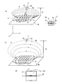
図1(a)は、本発明に係る金属対応センサであるセンサSを示す図であり、コイル2の軸方向と平行な面を有し磁性体6の一面に接する金属板M(金属部)の上にy方向に長い磁性体6の周囲にz,x面内に平行に巻くようにコイル2が巻回されて(以下、単に、「巻かれて」等とする)おり、ピッチP2(所定の間隔)だけy方向に進むように巻かれている。ここで、このコイル2(センサコイルともいう)には、矢印のような向きに電流Iが流れているとする。このとき、磁界Hは大まかに図の磁性体6の左の端部から右の端部に進むようにセンサS上部に水平磁界Hhを作る。なお、金属板Mは、金属でできた板に限られるものではなく、ある面が金属でできた物であればよく、以降、金属面Mと表記する場合もある。
FIG. 1A is a diagram showing a sensor S that is a metal-compatible sensor according to the present invention, and has a metal plate M (metal part) that has a surface parallel to the axial direction of the
この水平磁界Hhが存在するコイル2の軸方向と同一の方向、即ちセンサSの長手方向(y方向)の磁界を切るように、ICタグT(情報記録媒体)のコイルCt(タグコイルともいう)がセンサコイルと平行となるように設置された場合は、図に示すようにセンサSの磁界(特に水平磁界Hh)とタグコイルとが結合(電磁結合)し、誘起電圧Vを発生させる。そして、タグコイルがICのコンデンサにより共振状態にあるときは、タグコイルに大きな共振電流が流れ、ICタグTのICに電力を供給すると共に、ICの信号電流もコイルCtに流れることにより、ICタグTによる磁界が新たに発生する。そして、これが信号となって再びセンサSで受信され、センサS上部のICタグT即ちタグが取付けられたターゲットに関する情報の信号を読み取り(すなわち、情報の送受信を行う)、センサSの先に取付けられたリーダライタ(R/W)を介してPC等のコンピュータで、ICタグTが貼り付けられた対象物(ターゲット)の管理を行うことができる(図10参照)。
The coil Ct (also referred to as tag coil) of the IC tag T (information recording medium) so as to cut the magnetic field in the same direction as the axial direction of the
図1(a)はセンサSの斜視図で、図1(b)はセンサSのy軸に垂直な方向に切断した場合の断面図であり、この図はセンサSを横から(y方向から)見た場合であるともいえる。 1A is a perspective view of the sensor S, and FIG. 1B is a cross-sectional view when the sensor S is cut in a direction perpendicular to the y-axis. This figure shows the sensor S from the side (from the y direction). It can be said that this is the case.
金属面Mの上に載せられているセンサSは、コイル2と磁性体6の影像(イメージ)が下方(図ではz軸マイナス側:図中破線で示す)に発生し、センサSの断面積S1は下方の断面積と加えて2倍(=2S1)となり、感度が2倍となることが知られている。すなわち、金属板Mは、センサSの感度を向上させる。それ程向上しないこともあるが、負(マイナス)効果とはならない。
In the sensor S mounted on the metal surface M, an image (image) of the
図1(c)の場合には磁性体6の厚さTh2が、図1(a)の場合の厚さTh1と比べて厚くなりTh2>Th1であるので、断面積S2は断面積S1より大きくS2>S1となる(あるいは、S2=nS1(n>1))。このため磁束密度、即ちセンサSに流れる電流Iが同じ場合には、磁束は断面積Sに比例するので、断面積S2が大きい程磁束が増え、センサSの上部に励振される磁束は多くなり、従ってICタグTとセンサSとの通信距離d2は、図1(a)に示す厚さTh1の場合(断面積S1の場合)の通信距離d1に比べて大きくなることが分かる(d2>d1)(図1(d)参照)。磁性体6は角形の偏平な棒で示しているが、断面が楕円でもよく、例えば、楕円の短軸(bとする)の2倍が厚さTh、長軸(aとする)の2倍が幅Wとして類似させてもよい。なお、図1(b)、図1(d)のコイル2中の矢印は電流Iを示す。
The thickness Th 2 of the
従って、センサタグ間の通信距離dを大きくしたいときは、厚さTh即ち断面積S、コイル電流I、磁性体6の透磁率μrを上昇させる必要がある。ターゲットに取付けるICタグTのコイルCtの大きさについても同様であり、取付けるターゲットが金属の場合には金属親和性タグを取付けることにより、よりよい結果が得られる。なお、金属親和性タグとは、金属に阻害されることなく反対に金属面電流や磁流を利用し感度が向上する金属対応タグのことであり、金属面による影像を利用して感度を上昇させる金属面に親和性を有するタグをいう。
Therefore, when it is desired to increase the communication distance d between the sensor tag, it is necessary to raise the thickness Th i.e. the cross-sectional area S, the coil current I, the magnetic permeability mu r of the
センサS上でコイルCtに誘導される磁束φは次のように現されるので、この式からも上記を説明することがよく理解される。よくいわれているκI/d3はコイルの軸方向に限った磁界の強さである。 Since the magnetic flux φ induced in the coil Ct on the sensor S is expressed as follows, it is well understood that the above description is explained also from this equation. The well-known κI / d 3 is the strength of the magnetic field limited to the axial direction of the coil.
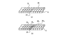
[給電部が中心にある場合のセンサについて]
図2には、本発明の管理用センサシステムのコイル2(アンテナコイル)(後述する2R,2L)と、磁性体6と、この下方に置かれた金属板Mおよびコイル2の給電部FPを示している。ここでは、センサSの中心部の給電部FPよりも図中左に巻かれているコイル2Lと、右に巻かれているコイル2Rの並列給電により、それぞれが5〜6巻されている。最初の並列部の間隔をP1とし、コイルのピッチ間隔をP2としており、P1は1〜10mmの比較的近接する間隔としている。次にコイルが進む角度ピッチ角により、次のコイルが来る間隔P2が定まる。ここで、コイルが進む角度ピッチ角とは、磁性体6が金属板Mに接する面に巻かれたコイル2(図中、磁性体6と金属板Mの両方に接するように描かれた斜めの破線部分)が、x軸(図1参照)に対してなす角度のことである。すなわち、y軸からみると、コイル2が一巻きごとに進むことにより発生する間隔P2の原因となるもので、x軸からの角度である。このコイル間の間隔P2は一定でもよいし、端部では電流が弱くなるので、磁束密度を上げるためのピッチ間隔を狭くしてもよい(例えば、ピッチ間隔Pn)。この例では、両側に並列に2巻巻く構造を示しているが、並列に2巻あるいは3巻左右に巻くこともできるし、片端からコイルを巻くこともできる。
[Sensor when the power feeding unit is at the center]
FIG. 2 shows a coil 2 (antenna coil) (2R, 2L, which will be described later), a
コイル間のピッチ間隔P2は20mm前後であるが、1〜50mmと感度に合せてピッチを決めることができる。 Although pitch P 2 between the coils is around 20 mm, it is possible to determine the pitch in accordance with the 1~50mm and sensitivity.
例えば、本やファイルの厚みが20mm以上のときはICタグT(以下、単にタグTとする)間の干渉も少なく、従って共振のずれもあまり発生しないので、センサ長lm1は45cmのものでも充分な感度が得られる。センサ長lm1≒45cmは、本発明の管理用センサシステムをセンサ棚として用いる場合の棚幅90cmの半分の構成寸法より、実用的に定められる。 For example, when the thickness of a book or file is 20 mm or more, there is little interference between IC tags T (hereinafter simply referred to as “tag T”), and therefore there is not much resonance shift, so a sensor length lm 1 of 45 cm is sufficient. Sensitivity is obtained. The sensor length lm 1 ≈45 cm is practically determined from the component size half of the shelf width of 90 cm when the management sensor system of the present invention is used as a sensor shelf.
本やファイルの厚みが10mmとなった場合には、本等に貼り付けられたタグT間の干渉が大きくなり共振周波数も1〜2MHz程度もずれるので、センサ感度を上げないとタグTとの通信が難しくなる。従ってセンサ長lm1を、ターゲットの厚みが20mm以上の場合の約半分(1/2)とし、センサ長lm1≒22.5cmとし、電力を半分のセンサに集中することにより感度を上げることができる。この場合にはピッチ間隔P2は10mm程度となるが、1〜50mmと感度に合せて決めることができる。 When the thickness of the book or file becomes 10 mm, the interference between the tags T attached to the book or the like increases, and the resonance frequency also shifts by about 1 to 2 MHz. Therefore, unless the sensor sensitivity is increased, communication with the tag T Becomes difficult. Therefore, the sensor length lm 1 is set to about half (1/2) of the target thickness of 20 mm or more, the sensor length lm 1 ≈22.5 cm, and the power can be concentrated to the half sensor to increase the sensitivity. it can. Pitch P 2 in this case is of the order of 10 mm, it can be determined in accordance with the 1~50mm and sensitivity.
更に薄いファイルや紙束、プラスチックケース等の5mm程度の厚みを有するものにタグTを貼り付けて管理する場合には、センサ長lm1を更に半分(1/4)とし、センサ長lm1≒11.25cmとする。これにより、電力を小形に分けたセンサに集中することができ、感度を更に上げ干渉が発生しているタグTにおいても通信することが可能となる。この場合にはピッチ間隔P2はほぼ5mmで2〜20mm程度となる。絶縁コイルであるコイル2は、中心部の給電部FPより両側に分けて同方向に間隔P2で巻いている。更に薄いファイルや紙束、プラスチックケース等のターゲットや読み難い場合にはセンサ長lm1≒55.2mm程度とし、この場合にはピッチP2≒2.5mm(1〜5mm)程度となる。更に薄いターゲットや読み難い場合にはセンサ長lm1≒25.1mm程度とし、この場合にはP2≒1.25(1〜3mm)とすることができる。
When a tag T is attached to a thin file, a paper bundle, a plastic case or the like having a thickness of about 5 mm for management, the sensor length lm 1 is further halved (1/4), and the sensor length lm 1 ≈ 11.25 cm. As a result, the power can be concentrated on the small-sized sensors, and the sensitivity can be further increased and communication can be performed even in the tag T in which interference occurs. In this case, the pitch interval P2 is about 5 mm and about 2 to 20 mm.
図2によると磁性体6の上部の面のコイルは、コイル軸と直角即ち磁性体6の長さ方向(図1(a)でのy方向)に直角になるように巻いており、下方(裏側;金属面Mと接する側)でコイルのピッチを進めるようにしている(図中、コイル2の破線参照)。コイル2の巻き方としては、上面,下面共にピッチ角をもたせ、上面や下面から見るとコイルが両面とも傾くような巻き方をしても良い。
According to FIG. 2, the coil on the upper surface of the
図2(a)はセンサコイルの斜視図を示したもので、磁性体6の幅W、長さlm1、高さ(或いは厚さ)Th1のコア(磁性体6)に絶縁線であるコイル2を左右に対称に巻いている。ここで、磁性体6の幅とはコイル軸方向に垂直でかつ金属板Mの面に平行な辺の長さで(図1(a)のx方向の長さ)、磁性体6の長さとはコイル軸方向に平行な方向の長さ(図1(a)のy方向の長さ)、磁性体6の高さ(厚さ)とはコイル軸方向に垂直でかつ金属板Mの面に垂直な辺の長さ(図1(a)のz方向の長さ)のことである。センサSの長さlm1は自由に構成できるが、棚の長さ90cmの約1/2の約45cmか、1/4の約22〜22.5cmか、1/8の約11〜11.2cmと構成するのが都合がよい。センサSの長さlm1は、棚の長さや箱の長さ、大きさ、引き出しの長さや大きさにより合せて構成する。要はタグ間の間隔が狭くなればセンサコイルも密巻として、タグコイルとの結合をタグコイル直下でとれるようにする。従ってタグ間の間隔に近いコイルのピッチ間隔とすることにより、感度を上昇させている。
FIG. 2A shows a perspective view of the sensor coil, which is an insulated wire to the core (magnetic body 6) of the
一方、磁性体6の幅Wは3〜10cm程度で標準的に7cm程度のものを使用している。本や書類のずれあるいはこれに取付けられるタグTの大きさや媒体のズレ等をカバーするため等により、多少幅を調整しなければならないことがある。一般に磁性体6の高さTh1を増した方が磁束は増え、従って外部の磁界も強くなるが、透磁率の大きさにもより、ゴムフェライトによる場合には、床厚はあまり厚くない方が好ましいので、高さTh1を1〜15mm程度にしており、中間の7〜10mm程度の磁性体を用いている。
On the other hand, the width W of the
コイル2は、ピッチP1(0〜10mm)をあけて端部に向けてP2のピッチで5〜6巻磁性体6の周囲に巻き、終端は接地側とし中心部までケーブルで接続する。同時に下方の金属板Mに接地を行っても良い。接地側は給電用同軸ケーブルの外部導体側とすることができる。コイル2のピッチP2 5〜30mmはほぼ同じでよいが、上述したように端部の方ではややピッチPnを短くし、端部の磁束が落ちるのを防ぎ、センサSの長さlm1に渡って磁束を均一化することができる。
The
センサ上部にタグTが縦に置かれ、センサSより発生した磁束がこのタグTのコイルCtと鎖交する。タグコイルにはICが接続され、ICの容量が約22pF程度であり、コイルCtのインダクタンスは6μH程度で、周波数13.56MHzでほぼ共振するように作られている。このようなタグTが図書、ファイル、プラスチック板や箱に貼られてセンサSの上に並べられており、このタグTとセンサコイルから発生する磁界との通信を行っている。図2(a)中タグTnは、n番目に並べられたターゲットに貼付されたタグを表している。センサコイルのインダクタンスはコイル2を多数巻き過ぎると大きくなり過ぎ、また少な過ぎると小さくなり過ぎる。このインダクタンスに合ったコンデンサを直列や並列に接続し、共振周波数を合せると共に、インピーダンスの整合も行っている。
The tag T is placed vertically on the sensor, and the magnetic flux generated from the sensor S is linked to the coil Ct of the tag T. An IC is connected to the tag coil, the capacitance of the IC is about 22 pF, the inductance of the coil Ct is about 6 μH, and it is made to resonate substantially at a frequency of 13.56 MHz. Such a tag T is attached to a book, a file, a plastic plate or a box and arranged on the sensor S, and communication between the tag T and a magnetic field generated from the sensor coil is performed. FIGS. 2 (a) Medium tags T n represents a patch tag to the target arranged in the n-th. The inductance of the sensor coil becomes too large when the
使用周波数が13.56MHzである場合は、インダクタンスの値が約0.5μH〜9μH程度であるので、直列に等価なコンデンサの値は約10〜250pF程度となる。またコイルの巻数が粗となり過ぎると、インダクタンスの値は小さくなるだけでなく磁界分布にむらが生じ、従ってタグTと通信ができない場所が発生する。 When the operating frequency is 13.56 MHz, the inductance value is about 0.5 μH to 9 μH, so the equivalent capacitor value is about 10 to 250 pF. If the number of turns of the coil becomes too coarse, not only the inductance value becomes small, but also the magnetic field distribution becomes uneven, so that a place where communication with the tag T cannot be performed occurs.
また、コイル2の巻数を密にし過ぎるとインダクタンスはかなり高くなり、磁界のムラも発生し共振や整合がとれ難くなり、先端に行くに従って減衰も多くなる。また給電部FPで整合器によりインピーダンスを50Ωに整合させるときはスミスチャートの上半分、即ちインダクティブにしておいた方が直並列のコンデンサのみで整合がとれるので調整し易い。
Further, when the number of turns of the
コイル2を並列に2本巻くようにすると、巻数を少なくすることができるし、コイルのピッチも密にすることもでき、かつインダクタンスもそれ程上がらない。並列のコイルを何本巻くかはターゲットによっても異なる。
If two
コイルの端部はそのまま接地してもよいし、1000pF〜2000pF程度のコンデンサを介して下の金属面Mに接地してもよい。 The end of the coil may be grounded as it is, or may be grounded to the lower metal surface M through a capacitor of about 1000 pF to 2000 pF.
図2(b)は図2(a)のセンサSを横(図1(a)のy方向)から見た場合で、断面図とも考えられる。中心には磁性体6による磁芯があり、この周囲にコイル2が巻かれており、更に保護と絶縁の目的の絶縁プラスチックシートPSが巻かれ、鉄板(センサホルダ)(センサ収容部)MCで枠を作り、磁性体コイルセンサであるセンサSを収納し、この上にカバーとしてプラスチック板PP(以下、センサカバーPPとする)が載っている構造となっている。このように、センサSはユニット化され、以降、これをセンサユニットと記すこともある。コイルはプラスチックシートなしに直接磁性体に巻くこともできるが、密着度によってインダクタンスの変化が大きくなり不安定となるので、プラスチックシートPSを巻いている。
FIG. 2B shows the sensor S of FIG. 2A viewed from the side (the y direction of FIG. 1A) and can be considered as a cross-sectional view. At the center is a magnetic core made of a
図2(b)で、金属板Mとしての役割を果たすセンサホルダMCによる影像(イメージ)が金属板M(この場合はセンサホルダMC)の金属面の下方に生じ、コイル2による影像(イメージ)がコイル2i、磁性体6の影像(イメージ)が磁性体6iとなり現れている。なお、Iiは電流Iの影像(イメージ)、Hhiは水平磁界Hhの影像(イメージ)である。
In FIG. 2B, an image (image) by the sensor holder MC that plays the role of the metal plate M is generated below the metal surface of the metal plate M (in this case, the sensor holder MC), and an image (image) by the
下方の影像(イメージ)効果により、コイル2とコイル2iにより、コイルの断面と磁性体が2倍となり磁束が2倍となる。
Due to the lower image effect, the
即ち、金属面M(又はセンサホルダMC)により上方のみに磁界が集められ、下方の磁界が上方に加算されることにより、上部空間USの磁束密度が約2倍となり感度が上昇する(すなわち、感度を向上させる)。金属面の大きさが小さくイメージ効果が少ない場合は、感度の上昇は2倍とはならない。 That is, the magnetic field is collected only upward by the metal surface M (or the sensor holder MC) and the lower magnetic field is added upward, so that the magnetic flux density in the upper space US is approximately doubled and the sensitivity is increased (that is, Improve sensitivity). If the metal surface is small and the image effect is small, the increase in sensitivity will not be doubled.
図2(c)はコイル2の巻き方を示すものでセンサSの中心部で給電して左右にコイル2を巻き、右に巻くコイルを2Rとし、左に巻くコイルを2Lとしており、コイル2により生ずる磁界が同一方向を向くように巻いている。図によりコイルの中心部を通る磁界は左へ向って流れているが、コイルの外の上を通る磁界(水平磁界Hh)は全体として右へ向って流れている。
FIG. 2 (c) shows how to wind the
図2(d)はコイル2の巻き方を反対(例えば左回り)とした場合を示す。図2(c)の右回りの場合も図2(d)の左回りの場合も一定方向の巻きであれば交番磁界であるので、同じ結果となる。図2(c)のセンサの向きを180°回転させると図2(d)のセンサと同一となることからも同一であることが分かる。
FIG. 2D shows a case where the winding method of the
[センサを並べたセンサユニットについて]
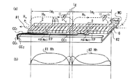
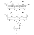
図3にはセンサ長lm1を約1/2とし、同一電力を加えることによりセンサに加わる電力を2倍とし、磁界を強め通信感度を上昇させる方法を示したものである。センサを小形にすることにより電力を集中し、感度を上昇させる効果があるが、一方センサアンテナとしては小形となるため、磁束密度が減少する方向となるため多少の欠点は伴う。しかし、タグコイルとセンサコイルとの結合が密となるため、期待するよい結果が得られている。
[Sensor unit with aligned sensors]
FIG. 3 shows a method of increasing the communication sensitivity by increasing the magnetic field by setting the sensor length lm 1 to about ½, doubling the power applied to the sensor by applying the same power, and increasing the magnetic field. By making the sensor small, there is an effect of concentrating electric power and increasing the sensitivity. On the other hand, since the sensor antenna is small, the magnetic flux density tends to decrease, so there are some drawbacks. However, since the coupling between the tag coil and the sensor coil is dense, an expected good result is obtained.
磁性体6にコイル2を同様に巻いているが、磁性体長が約半分lm2(=lm1×1/2)になるため、コイル2のピッチは半分となりP1の値も約半分、P2の値も約半分となってコイル間の幅すなわちコイル間隔は狭くなる。lm2は45/2≒22.5cmとし、センサを2ケ用いて45cmとするため22.5cmより少し短めで2個のセンサ間には5〜10mmの間隙lgを設けている。この間隙lgにはセンサが存在しないので、磁界の強度が落ち込むが、この落ち込みを改善する方法を述べる。なお、2個のセンサをそれぞれセンサ#1、センサ#2とし、センサ#1のコイルに流れる電流をI1、センサ#2のコイルに流れる電流をI2とする。このように、2以上のセンサを並べる場合には、それぞれのセンサのコイルの軸方向が揃うように(一致するように)する。
The
センサ間の間隙lgをもたせず磁性体を連続させると、第1コイル(センサ#1のコイル)と第2コイル(センサ#2のコイル)あるいはセンサ#1とセンサ#2との結合が大きくなり調整が難しくなるので、それぞれのセンサを分離するには間隙lgを設けた方がよい。この間隙lgは0mm〜15mm前後で3〜5mm程度がよい。
If the magnetic material is made continuous without providing the gap lg between the sensors, the coupling between the first coil (coil of sensor # 1) and the second coil (coil of sensor # 2) or
センサ#1とセンサ#2は同一のリーダで分岐端子(チャンネル)の切換により給電および励振することができる。
センサの給電部FPとリーダとセンサを接続する同軸ケーブル(CC1やCC2)の間に整合するためのコンデンサやインダクタンス(整合器Mat)を載せるための基板PCBが存在する。 There is a substrate PCB on which a capacitor and an inductance (matching unit Mat) for matching are placed between the sensor power supply unit FP and a coaxial cable (CC 1 or CC 2 ) connecting the reader and the sensor.
図3(b)はセンサ上面で約2mm〜10mm上の磁界分布を示している。 FIG. 3B shows the magnetic field distribution about 2 mm to 10 mm on the upper surface of the sensor.
実線による磁界強度の分布は左のセンサ#1によるもので、ほぼ磁性体の端部に近い所あるいは一番端部のコイルに近い所で、水平に一定方向の磁界(水平磁界Hh)は零となる。この部分で磁界が垂直に立ち上がり(垂直磁界Hv)、右側に向う反対向きの磁界となるため水平磁界Hhが零となる。
The distribution of the magnetic field strength by the solid line is due to the
端部においては、水平磁界Hhは弱いが、センサの中心部に行くにつれ強くなり、また右側の端部で同様のことが起こり、水平磁界Hhは零となる。この点で磁界の方向が変わり、また右側に行く間に隣のセンサ#2を励振し、少し磁界強度が増すが、再び下がって来る。そしてセンサ#2の端部でまた磁界強度を増すような形状となる(実線)。
At the end, the horizontal magnetic field Hh is weak, but becomes stronger as it goes to the center of the sensor, and the same occurs at the right end, and the horizontal magnetic field Hh becomes zero. At this point, the direction of the magnetic field is changed, and the
一方、センサ#2による磁界強度を一点鎖線で示す。センサ#2の磁界強度はセンサ#1の磁界強度分布と、センサ#1とセンサ#2の間隙を中心として対称的になる。
On the other hand, the magnetic field intensity by the
図3(b)を見ても分かる通り、センサ#1の感度が零となる所はセンサ#2の感度の山があるので、センサ#1でこの上のタグTが読めない場合もセンサ#2でセンサ#1の上のタグTを読むことが可能となる。センサ#1とセンサ#2の継ぎ目の磁界強度の低下を補うだけでなく、一番左のセンサ#1の端部においてもセンサ#2の磁界があり、これで読むこともできる場合がある。
As can be seen from FIG. 3B, the
一方、センサ#2の一点鎖線による磁界の分布においてもセンサ#2の端部において磁界が零になる所でもセンサ#1の磁界が強くなっているためセンサ#2の上のタグTを読むことができる。
On the other hand, even in the distribution of the magnetic field by the alternate long and short dash line of
このように、センサの端部で水平磁界Hhが零となる所はセンサ端部に近い最終コイルの電流から発生する磁界と他のコイルから発生する磁界の合成により端部で磁界が上方に折り曲り、再びセンサ上部で水平磁界Hhになる部分とその部分では曲らないで広がって行く磁界に分かれるために、一部の磁界が垂直磁界Hvのように見える。従ってセンサ端部のこの部分は垂直磁界Hvが強く現れる。 Thus, the place where the horizontal magnetic field Hh becomes zero at the end of the sensor is that the magnetic field is folded upward at the end by combining the magnetic field generated from the current of the final coil close to the end of the sensor and the magnetic field generated from other coils. A part of the magnetic field looks like a vertical magnetic field Hv because it is divided into a part that becomes a horizontal magnetic field Hh at the upper part of the sensor and a magnetic field that expands without bending at that part. Therefore, a strong vertical magnetic field Hv appears at this portion of the sensor end.
[図書用金属棚へのセンサの設置(センサ棚としての使用)]
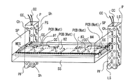
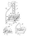
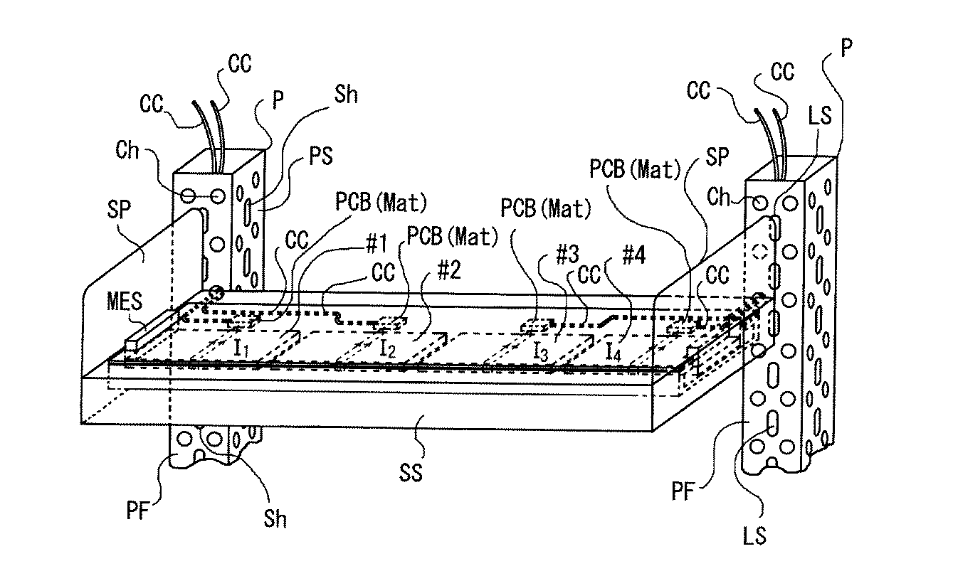
図4はこのようなセンサをアルミまたは鉄板により構成された図書用金属棚SSに取付け、本発明のセンサ棚とした場合の説明図である。一般に図書棚の幅は90cmか180cmであり、どちらかといえば90cm幅が多い。図4には棚を1段のみしか示していないが、一般的にはこのような棚が上下に5〜6段並んでいる。図書棚の場合、一棚が50〜60kgの重さに耐えられるように作られている。従って板を折り曲げたり、中空状の構造を作ったりして、強度が得られるように工夫されている。
[Installation of sensors on metal shelves for books (use as sensor shelves)]
FIG. 4 is an explanatory diagram in the case where such a sensor is attached to a book metal shelf SS made of aluminum or iron plate to form a sensor shelf of the present invention. Generally, the width of the book shelf is 90 cm or 180 cm, and if anything, it is 90 cm wide. Although only one shelf is shown in FIG. 4, generally such shelves are lined up 5 to 6 in the vertical direction. In the case of a book shelf, one shelf is made to withstand a weight of 50-60 kg. Therefore, it is devised so that strength can be obtained by bending a plate or making a hollow structure.
本発明に係るセンサ棚としての図書棚は、図2または図3で説明したセンサを収容できるようにチャンネル構造で幅広の溝のように構成され、これに図2(b)のような断面を有する下方および側方が、金属面(図2(b)ではセンサホルダMC)で構成されるセンサが嵌合するように構成されている。更にこの上に棚面と同一平面となるようにポリカーボネイトやABS等で作られたプラスチックカバーが載せられ、この上に本や書類や媒体等にタグTが貼り付けられた管理するターゲットとなる物品が載せられるようになっている。 The book shelf as the sensor shelf according to the present invention is configured as a wide groove with a channel structure so as to accommodate the sensor described in FIG. 2 or FIG. 3, and has a cross section as shown in FIG. The lower side and the side are configured so that a sensor constituted by a metal surface (sensor holder MC in FIG. 2B) is fitted. Furthermore, a plastic cover made of polycarbonate, ABS, or the like is placed thereon so that it is flush with the shelf surface, on which a tag T is attached to a book, document, medium, etc. It can be loaded.
図4ではセンサ(又はセンサユニット)が#1,#2,#3,#4と4つ並べられている様子を示す。 FIG. 4 shows a state where four sensors (or sensor units) are arranged in # 1, # 2, # 3, and # 4.
それぞれのセンサユニットは整合部PCB(Mat)基板を介して給電され1.5D等の同軸ケーブルCCで給電されている。給電用の同軸ケーブルCCはセンサ脇のスペースを通って板金(センサホルダ)MCの一部を欠いた隙間より、角パイプP(支柱)の前面PFや側面PSに開けてある穴Ch(穴部)を通って角パイプPの中を通り配線され、不図示のリーダライタR/Wの置かれている所あるいは分岐給電部まで配線される。 Each sensor unit is supplied with power through a matching portion PCB (Mat) substrate and is supplied with a coaxial cable CC such as 1.5D. The coaxial cable CC for power feeding passes through a space beside the sensor, and a hole Ch (hole) formed in the front surface PF or side surface PS of the square pipe P (support) through a gap lacking a part of the sheet metal (sensor holder) MC. ) Through the square pipe P, and is wired to a place where a reader / writer R / W (not shown) is placed or to a branch feeding unit.
角パイプP(以降、角柱Pともいう)の前面PFには側板SPを止めるための長穴(溝)LSが開けられ、また同軸ケーブルCCを通す穴Chが開けられている。 A long hole (groove) LS for stopping the side plate SP is formed in the front surface PF of the square pipe P (hereinafter also referred to as a prism P), and a hole Ch through which the coaxial cable CC is passed is formed.
角柱Pの側面PSには前後の遮蔽板SMP(遮蔽手段)(図9(a)参照)を止めるための長穴(溝)Shが開けられている。同軸ケーブルCCを通す穴Chをこの側面に開けてもよい。 A long hole (groove) Sh for stopping the front and rear shielding plates SMP (shielding means) (see FIG. 9A) is formed in the side surface PS of the prism P. A hole Ch through which the coaxial cable CC passes may be formed in this side surface.
側板SPが金属板の場合(この場合を金属側板MSPという)には後に説明する磁界の誘導路となる磁性体MES(誘導手段)が置かれており、金属面による磁界のブロックが発生しないようにしている。 When the side plate SP is a metal plate (this case is referred to as a metal side plate MSP), a magnetic body MES (guidance means) serving as a magnetic field guiding path, which will be described later, is placed so that the magnetic field is not blocked by the metal surface. I have to.
もし、側板SPがFRP等のようにプラスチックで構成されている場合には、磁界は端部でブロックされずに隣のセンサまで連続し、磁性体MESは不要となる。なお、センサ#1〜センサ#4のコイルに流れる電流を電流I1〜I4としており、センサの詳細は省略して図示している。
If the side plate SP is made of plastic such as FRP or the like, the magnetic field is not blocked at the end and continues to the adjacent sensor, and the magnetic MES is not required. Incidentally, the current flowing through the coil of the
[図書棚に並べられた図書に貼り付けられたタグの読み取り]
図5には図4の図書用金属棚SS(以下、図書棚SSとする)を正面から見た図を示す。
[Read tags pasted on books on the bookshelf]
FIG. 5 shows a front view of the book metal shelf SS of FIG. 4 (hereinafter referred to as the book shelf SS).
図書棚SSの上には図書Bが一部並べられている。図書Bの表紙あるいは裏表紙の下方にはタグTが取付けられ、センサから発生する水平磁界Hhと結合するようになっている。実際には下方(センサ)のコイル電流とタグTの電流が結合しているのであるが、一方ではコイル電流による磁界とタグTの電流による磁界が結合をしていると見てもよい。従って、タグTが近接するように並べられている場合にはセンサコイルも密巻にしてそれぞれのタグTのコイルとの結合を容易にする方がより確実にタグTを捕捉できる。 A part of the book B is arranged on the book shelf SS. A tag T is attached below the front cover or back cover of the book B so as to be coupled with a horizontal magnetic field Hh generated from the sensor. Actually, the coil current on the lower side (sensor) and the current of the tag T are combined, but on the other hand, it may be considered that the magnetic field generated by the coil current and the magnetic field generated by the current of the tag T are combined. Therefore, when the tags T are arranged so as to be close to each other, it is possible to capture the tag T more surely by making the sensor coils densely wound to facilitate the coupling with the coils of the respective tags T.
図書棚SSは両側の角柱Pの溝LSに嵌め込まれた側板SPにより支えられている。ここで、側板SPが金属板の場合は、金属側板MSPにより支えられることとなる(図5では金属側板MSPを使用した例を示している)。 The book shelf SS is supported by side plates SP fitted in the grooves LS of the prisms P on both sides. Here, when the side plate SP is a metal plate, it is supported by the metal side plate MSP (FIG. 5 shows an example in which the metal side plate MSP is used).
図書棚SSは図4でも述べたように金属板を加工したセンサの土台となる金属棚と、この上に収まるセンサホルダMCとセンサ#1,#2,#3,#4から成り立っており、これらのセンサ#1〜#4が同軸ケーブルCCで給電されている。
As described in FIG. 4, the book shelf SS is composed of a metal shelf that serves as a base of a sensor obtained by processing a metal plate, a sensor holder MC and
側板SPが鉄板、すなわち金属側板MSPである場合には金属側板MSPに誘導される電流により磁界が打ち消されて、センサ上部の磁界が弱くなったり、コイルの中心の磁性体6に流れる磁界を弱めたりしないように、磁界のガイドとなる磁性体MES(コーナ磁性体MES)を備え、一番端部の図書Beに貼り付けられたタグTeでも読めるようにしている。
When the side plate SP is an iron plate, that is, a metal side plate MSP, the magnetic field is canceled by the current induced in the metal side plate MSP, the magnetic field at the top of the sensor is weakened, or the magnetic field flowing through the
もし磁界が通る磁性体コア部の先にプラスチック側板が存在するようであれば、このようなコーナ磁性体MESは不要となる。なお、タグTnは、図書棚SS上に並べられたn番目の図書Bに貼付されたタグを表す。 If a plastic side plate is present at the tip of the magnetic core portion through which the magnetic field passes, such a corner magnetic body MES is not necessary. Incidentally, the tag T n represents the tag attached to the n-th book B which are arranged on the book shelf SS.
[センサのコイルの巻き方について]
図6にはコイル2を磁性体6の中心部より巻いた場合、インダクタンスが大きくなり過ぎないように並列に2本ずつ巻いて行く場合を図6(a)(2R,2L)に、並列に4本ずつ巻いて行く場合を図6(b)(2R1,2R2,2L1,2L2等)に示す。もちろん奇数本並列にしてもよい。
[How to wind the sensor coil]
FIG. 6 shows a case where two coils are wound in parallel so that the inductance does not become too large when the
図2,図3,図6ともに中心よりコイルを左右に巻いているが(2L,2R等)、片側からコイルを巻いても良い。この場合には並列とならず直列となるためコイルのインダクタンスは増え過ぎないようにしなければならないし、コイルに流れる電流も減衰等によりバラつかないように気をつけなければならない。 In FIGS. 2, 3 and 6, the coil is wound from the center to the left and right (2L, 2R, etc.), but the coil may be wound from one side. In this case, since it is not parallel but in series, the inductance of the coil must be prevented from increasing excessively, and care must be taken so that the current flowing through the coil does not vary due to attenuation or the like.
このような磁性体センサでは磁性体の比透磁率μrの影響を大きく受け、電磁波のケーブルに沿う遅波率(短縮率)は、比誘電率をεrとすると、
![]()
![]()
このようなコイルの巻線においては、一般のソレノイド形のコイルの特性の他に、コイルに沿って流れる電流が遅波率の影響を受け、位相が徐々に遅れて行くことになり、微小コイルのように同相の電流のみで扱うことができなくなる。またコイルも粗巻となるため、コイルの軸方向に沿う磁界と平行な外部の水平磁界Hhのみならず垂直磁界Hvも発生する。従ってタグTが多少傾いたり横になったりした場合でも多少条件がよく通信が可能となる。 In such a coil winding, in addition to the characteristics of a general solenoid type coil, the current flowing along the coil is affected by the slow wave rate, and the phase gradually delays. It becomes impossible to handle only with the current of the same phase. Further, since the coil is also coarsely wound, not only an external horizontal magnetic field Hh parallel to the magnetic field along the axial direction of the coil but also a vertical magnetic field Hv is generated. Therefore, even when the tag T is slightly tilted or lies down, it is possible to communicate with a slightly better condition.
図6にはコイルを磁性体6センサの中心より左右に並列に巻いた場合を示す。
FIG. 6 shows a case where the coil is wound in parallel from the center of the
図6(a)は左右に1本ずつ磁性体6の上にコイルを巻き、並列にした場合を示す。右側に巻くコイルは2Rで示し、左側に巻くコイルは2Lで示してある。左右合せて2巻で示してあり、上部に現れるコイルは直角に下部でピッチ分の進みを持たせている。ピッチは上下平等に1/2ずつ持たせることもできる。
FIG. 6A shows a case where coils are wound on the
図6(b)は左右並列に2本ずつ巻いた場合を示す。この場合には給電部FPより見ると並列に4本巻いていることになる。 FIG. 6B shows a case where two are wound in parallel on the left and right. In this case, four wires are wound in parallel when viewed from the power feeding unit FP.
磁性体のほぼ中心より左右に対称になるようにコイルを巻いているが、片側から巻き始め、直列にコイルを他の端部に向って向くこともできる。この場合コイルの巻数が多くなり過ぎ、インダクタンスが大きくなり過ぎたり、電流の振幅が落ちたり、長く巻き過ぎた場合に電流の位相が変化し、磁界が必要な方向に加算されないようなことも発生するので気をつけなければいけない。 Although the coil is wound so as to be symmetrical from the center of the magnetic body to the left and right, it is also possible to start winding from one side and direct the coil toward the other end in series. In this case, if the number of turns of the coil becomes too large, the inductance becomes too large, the current amplitude drops, or if the winding is too long, the phase of the current will change and the magnetic field may not be added in the required direction. You have to be careful.
[補助アンテナ(補助センサ)について]
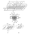
図7には補助アンテナ(補助センサ)(補助手段)の効果について実施例をもとに説明する。
[About auxiliary antenna (auxiliary sensor)]
FIG. 7 explains the effect of the auxiliary antenna (auxiliary sensor) (auxiliary means) based on the embodiment.
図7(a)はセンサ#1(センサアンテナ#1)とセンサ#2(センサアンテナ#2)の間に補助センサSub(補助アンテナSub)を置いた場合を示す。 FIG. 7A shows a case where the auxiliary sensor Sub (auxiliary antenna Sub) is placed between the sensor # 1 (sensor antenna # 1) and the sensor # 2 (sensor antenna # 2).
図3で説明したように、センサ#1とセンサ#2はある程度結合しており、それぞれが補うようにして磁界の感度が零となる所を補っているが、図7(a)の場合にはセンサ#1とセンサ#2はもっと離れていても補助センサSubが存在しているため、この間を埋める役割を果たしてくれる。なお、センサ#1、#2は、補助センサSubに対して主センサということもできる。
As described in FIG. 3, the
センサ#1(またはセンサ#2)と補助センサSubの間隙をlgmgとする。補助センサSubの長さをlssとし、幅をWとする。ここで、センサ#1とセンサ#2の長さはlms、幅はWである。補助センサSubの磁性体6は主センサ#1,#2と同じ物でよいが、長さlssはあまり長くしない方がよい。長さlssは1〜3cm程度でよい。補助センサSubに巻かれたコイル2−1(第一のコイル)とコンデンサC(第一の共振器)により共振をとり、センサ#1あるいはセンサ#2により励振される磁界をこの共振器で励振し、補助センサ上部に強い磁界Hhssを発生させることができる。共振器の電流は、同相でも進み90°位相でもよい。なお、簡単のためセンサ#1、センサ#2のコイル2は省略している。また、補助センサSubをセンサ#1とセンサ#2の間に配置する場合は、コイル2−1のコイル軸方向がセンサ#1やセンサ#2のコイル軸方向と揃うようにする。
The gap between the sensor # 1 (or sensor # 2) and the auxiliary sensor Sub is set to lgmg. The length of the auxiliary sensor Sub is lss and the width is W. Here,
図7(b)には補助センサSubにより発生する磁界によりセンサ#1、センサ#2の磁界の落ち込みを補足し、水平磁界Hhが連続し落ち込みがなくなることを示している。
FIG. 7B shows that the magnetic field generated by the auxiliary sensor Sub is supplemented by the magnetic field drop of the
センサ#1による磁界を破線で示し、センサ#2による磁界を一点鎖線で示し、補助センサSubによる磁界を点線で示し、補助センサSubにより落ち込みのなくなった連続磁界の強さを実線で示している。図7(b)では、見易くするために各線を少しずらして示している。
The magnetic field generated by the
図7(c)には直交する磁界を作る必要がある場合のセンサに用いる補助センサSubの例で、センサ#1とセンサ#2のつなぎの落ち込みを同じように補うことができることを示す。この場合には直交するコイル2−1(第一のコイル),コイル2−2(第二のコイル)を巻き、それぞれが別々にコンデンサC1(第一の共振器),コンデンサC2(第二の共振器)を接続し、共振回路として構成している。
FIG. 7C shows an example of the auxiliary sensor Sub used for the sensor when it is necessary to create orthogonal magnetic fields, and shows that the drop in the connection between the
[誘導装置について(磁性体による誘導路)]
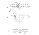
図8には金属棚である図書棚SSの端部で、金属側板MSPにより支えられている時に、金属側板MSPによりセンサ磁界が打ち消されるのを防ぐ場合の磁路の誘導装置MES(図4における磁性体MES)(誘導手段)を示している。
[Guiding device (guideway with magnetic material)]
FIG. 8 shows a magnetic path guidance device MES (in FIG. 4) for preventing the sensor magnetic field from being canceled by the metal side plate MSP when it is supported by the metal side plate MSP at the end of the book shelf SS which is a metal shelf. Magnetic body MES (induction means) is shown.
図書棚SSとその窪みに収容されている金属親和性センサMISS(Metal Intimate Smart Sensor)とそのケースMC(センサホルダMC)および、棚カバーSCの断面を右側に示しており、磁性体6とケースMCとその空間SPC、棚カバーSCの構成を示している。ここで、金属親和性センサMISSとは、図2(b)、図3、図4で説明したような、本願発明に係る金属対応センサ(又は金属対応センサユニット)のことをいう。
The cross section of the metal affinity sensor MISS (Metal Ultimate Smart Sensor) and its case MC (sensor holder MC) and the shelf cover SC housed in the book shelf SS and its recess is shown on the right side, and the
磁性体6にコイル2が巻かれ、このコイル2に電流Iにより発生する磁界Hがセンサの左端で金属製の図書棚SSを支える金属側板MSPに妨がれるような状態となる。この磁界Hを金属側板MSPに沿って誘導するための磁性体による磁路MGを設け、水平磁性体(すなわち磁性体6)に誘導されている磁界Hを垂直方向に導き、更に上方に逆L字形誘導路ML(図8(b)参照)により垂直磁界Hを更に水平磁界Hhとし、端部で減少する水平磁界Hhを補足する役割を持つ。そして、金属側板MSPの悪い影響を改善しながら端部で落ちる水平磁界Hhが増強され、図5にも示した端部に並べられる図書Beの2,3冊分の図書に取付けられたタグTeとセンサとの通信を改善することができる。図8(a)、図8(b)に示すようにセンサコイルの電流Iとタグコイルの電流iとが磁界Hによって結合していると考えても良い。
The
図8(b)にはコイル2が巻かれたセンサの端部のみ拡大した図で、電流Iにより励振された内部磁界Hが誘導磁路MGに沿って上方に導かれ、更に逆L字形誘導路MLに沿って一部が右へ水平磁界Hhとなって誘導される様子を示す。
FIG. 8B is an enlarged view of only the end of the sensor around which the
誘導磁路MGの厚みdsは5mm〜10mm程度でよいが、透磁率の高いよい磁性体であるならば1〜2mm程度の厚みで満足な結果を得ることもできる。上部の逆L字形誘導路MLの磁性体は図書等に貼りつけられたタグTの大きさ、位置に合わせ、かつ図3や図7で説明した水平磁界Hhと連続し、タグTとの通信が行われ易い位置と大きさに合せればよい。誘導路MLの戻り部分dmの厚みは約5mm〜15mmでよいが、この厚みは図書や媒体が積まれるスペースファクターにもより、できるだけ薄くする方が望ましいので、透磁率が高い磁性体の場合、誘導磁路MGの厚みdsが0.3〜2mmにでき逆L字の戻り部分dmの長さは3〜7mm程度でもよい場合がある。 The thickness ds of the induction magnetic path MG may be about 5 mm to 10 mm, but a satisfactory result can be obtained with a thickness of about 1 to 2 mm if the magnetic material has a high magnetic permeability. The magnetic body of the upper inverted L-shaped guide path ML matches the size and position of the tag T affixed to the book, etc., and is continuous with the horizontal magnetic field Hh described with reference to FIG. 3 and FIG. It is sufficient to match the position and size at which it is easily performed. The thickness of the return portion dm of the guide path ML may be about 5 mm to 15 mm, but it is desirable to make this thickness as thin as possible depending on the space factor on which books and media are stacked. The thickness ds of the induction magnetic path MG can be 0.3 to 2 mm, and the length of the reverse L-shaped return portion dm may be about 3 to 7 mm.
誘導装置MESがセンサの上に突起となって現れるので、これをカバーするためにプラスチックカバーMESCを取付け、センサカバーPPや棚カバーSCと連続させ、強度や外見を整える必要がある。この戻りの部分、あるいは垂直誘導部MGあるいは逆L字形誘導路MLの部分に共振コイル2dとコンデンサCdを巻き、端部の磁界を強くすることもできる。端部の磁性体の厚みdsやdmを小さくしながら、強い磁界を発生させるには共振コイル2dとコンデンサCdを加えることは有効である。
Since the guiding device MES appears as a protrusion on the sensor, it is necessary to attach a plastic cover MESC to cover the sensor, and make it continuous with the sensor cover PP and the shelf cover SC to adjust the strength and appearance. A
図8(c)は金属側板MSPが何故通信を害するかを説明する図である。 FIG. 8C is a diagram for explaining why the metal side plate MSP harms communication.
同図を見て分かるように、磁性体内部の磁界Hは金属側板MSPに衝突すると誘導電流Iicを誘起する。この誘導電流Iicにより発生する磁界Hrはセンサ電流Iにより造られた磁界Hとは逆相で打ち消す方向の磁界Hrである。このため、磁性体6の中を進んで来た磁界Hは端部で打ち消され弱くなってしまい、結果タグTと通信を行うための磁界Hも弱まり、通信ができなくなる。すなわち、金属側板MSPの傍に置かれた図書等の媒体(例えば、図5の図書Be)に貼り付けたタグT(例えば、図5のタグTe)との通信ができなくなり、棚による媒体の管理ができなくなるか、不完全なものとなる。
As can be seen from the figure, when the magnetic field H inside the magnetic body collides with the metal side plate MSP, an induced current Iic is induced. The magnetic field Hr generated by the induced current Iic is a magnetic field Hr in a direction that cancels out of phase with the magnetic field H created by the sensor current I. For this reason, the magnetic field H that has traveled through the
しかるに本発明の誘導磁路MESを用いることにより端部磁界を増強し、かつ金属側板MSPの影響も改善する一石二鳥の効果が得られる。 However, by using the induction magnetic path MES of the present invention, the effect of two birds with one stone that enhances the end magnetic field and also improves the influence of the metal side plate MSP can be obtained.
[インテリジェントシェルフについて]
図9には本発明の金属対応の媒体管理用センサである金属親和性センサMISS(Metal Intimate Smart Sensor)が、本発明のセンサ棚としての図書棚SSに応用された場合の説明図である。本発明の金属対応センサである金属親和性センサMISSを備えるセンサ棚である図書棚SSを、インテリジェントシェルフISという。
[About Intelligent Shelf]
FIG. 9 is an explanatory diagram in the case where a metal affinity sensor MISS (Metal Intimate Smart Sensor) which is a metal-compatible medium management sensor of the present invention is applied to a book shelf SS as a sensor shelf of the present invention. The book shelf SS that is a sensor shelf including the metal affinity sensor MISS that is a metal-compatible sensor of the present invention is referred to as an intelligent shelf IS.
図書館等の図書棚は実用上前後に5〜6段ずつ並べられることが一般的である(図9(a)参照)。 Library shelves, such as libraries, are generally arranged in 5-6 rows before and after practical use (see FIG. 9A).
このような場合、前後に感度のよいセンサが並べられるので、隣同士のセンサが近くなるため同時にリーダを動作させると磁界によるセンサ同士の磁気結合が発生し、それぞれのセンサが妨害を起こし、リーダがタグTの情報を読めなくなる。但し、同一リーダで読む場合には分岐器でスイッチングしており、オンオフが同期する状態となるので妨害は発生しない。 In such a case, since sensors with high sensitivity are arranged in the front and back, adjacent sensors are close to each other, and if the readers are operated simultaneously, magnetic coupling between the sensors due to the magnetic field occurs, causing each sensor to interfere, Cannot read the information of the tag T. However, when reading with the same reader, switching is performed by the branching device, and the on / off state is synchronized, so that no interference occurs.
これを防止、改善する本発明を実施例で示す。 The present invention for preventing and improving this will be described in Examples.
図9(a)はインテリジェントシェルフISである図書棚の斜視図で前後に2段(又は2列)上下に2段並べ、これを角柱Pで支えている例である。 FIG. 9A is a perspective view of a bookshelf that is an intelligent shelf IS, and is an example in which two stages (or two rows) are arranged vertically and supported by a prism P.
センサの機能についはこれまで詳しく述べているので省略してある。上下のセンサについては棚が金属で構成されているのと、上下の間隔があるため殆んどセンサ同士の結合はなく無視できる。しかるに前後のセンサとの距離は角柱Pであるポールを挟むのみで短く(近く)、脇に漏れる磁界が結合を起こす。コイル2や磁性体6の上部に強い磁界を発生しているが、脇の方にも弱い磁界が広がっている。従って隣にある前後のセンサ同士は結合し易い状態にある。
The sensor function is omitted because it has been described in detail so far. As for the upper and lower sensors, since the shelf is made of metal and there is an upper and lower interval, there is almost no coupling between the sensors and can be ignored. However, the distance between the front and rear sensors is short (near) just by sandwiching the pole that is the prism P, and a magnetic field leaking to the side causes coupling. A strong magnetic field is generated in the upper part of the
例えば図9(a)での手前(前)のセンサ#1aと奥(後)のセンサ#1bは隣同士で磁界の方向も同じでコイルも隣り合っている。従ってコイル同士は結合し易い状態である。センサ#2aとセンサ#2bも同様である。センサ#3aとセンサ#3bも同様である。センサ#4aとセンサ#4bも同様の状態である。このような場合には、今迄のように左右のセンサのみの結合や妨害を考えるのみでなく、前後のセンサの結合も考慮しなればならない。
For example, the front (front)
しかし、この隣同士のセンサの間に遮蔽する金属板の遮蔽板SMP(遮蔽手段)を設置することにより、前後の隣同士のセンサの結合を抑えることができた。遮蔽板SMPは鉄板、アルミ板、ステンレス板等の金属板でよい。金属板につめ(爪部)をつけ、棚の角柱Pの長穴Sh嵌め込むようにして固定することができる。このような遮蔽板SMPは、図9(a)、図9(b)に示すようにセンサ部を中心にある上下に幅を持たせて取付けてもよいし、上から下まで一枚の板で遮蔽を行ってもよい。重量や材料の経費を節約するため帯状板を、センサ部を中心に取付ければ、充分に遮蔽の効果が得られることが分かった。 However, by installing a shielding plate SMP (shielding means) made of a metal plate between the adjacent sensors, it was possible to suppress the coupling of the adjacent sensors. The shielding plate SMP may be a metal plate such as an iron plate, an aluminum plate, or a stainless plate. A claw (claw portion) is attached to the metal plate, and the metal plate can be fixed so as to be fitted into the long hole Sh of the prism P of the shelf. Such a shielding plate SMP may be attached with a vertical width centered on the sensor portion as shown in FIGS. 9A and 9B, or a single plate from top to bottom. Shielding may be performed with. It has been found that a shielding effect can be obtained sufficiently if a belt-like plate is attached around the sensor portion in order to save weight and material costs.
同一のリーダライタR/Wで読むときは、センサのチャンネル切換が同時に行われ、同期しているので、このような遮蔽の心配はない。リーダライタR/Wを並列に運転するときはこのような干渉や妨害が発生するので気をつけなければならない。センサの効力が多く従って切換チャンネル数も多く使用するリーダライタR/Wも多くなる図書館等では特に注意を要する。但し、並列運転をせねばならずセンサ間も干渉の発生のある所は同期切換を行えば干渉の問題は解消する。 When reading with the same reader / writer R / W, the sensor channels are switched simultaneously and synchronized, so there is no concern about such shielding. When the reader / writer R / W is operated in parallel, such interference and interference occur, so care must be taken. Special attention is required in a library or the like in which readers / writers R / W that use a large number of switching channels and a large number of sensor channels are used. However, the parallel operation must be performed and the problem of interference can be solved by performing synchronous switching in a place where interference occurs between the sensors.
図9(b)には前後2段(2列)、上下3段の金属棚が構成されている場合の横から見たインテリジェントシェルフISの説明図である。 FIG. 9B is an explanatory diagram of the intelligent shelf IS as viewed from the side in the case where metal shelves having two stages (front and rear) (two rows) and three stages on the upper and lower sides are configured.
図9(b)にはセンサの上に広がっている磁界を示しており、磁性体6のセンサ内部では紙面に向う矢印の方向の磁界を、磁性体センサ上部では紙面の向う側から手前に向う矢印の方向の磁界を示している。この脇に広がる磁界が前後のセンサ(例えばセンサ#1aとセンサ#1b)が結合することを示し、かつ遮蔽板SMPにより遮蔽されることを示している。完全にこのような磁界を遮断するには遮蔽板SMPは上下に連続させれば漏洩磁界による結合はなくなる。
FIG. 9B shows the magnetic field spreading on the sensor, and the magnetic field in the direction of the arrow pointing toward the paper surface inside the sensor of the
[センサとリーダライタ、PCとの接続]
図10には棚センサが前後に8個並べられた場合を上から見た状態で(すなわち、図9のインテリジェントシェルフISを上から見た状態)、このようなセンサがリーダライタR/W(読取書込装置)にどのように接続され、またコンピュータPCで制御、表示、管理されるかを説明する図である。
[Connection between sensor, reader / writer, and PC]
FIG. 10 shows a state in which eight shelf sensors are arranged at the front and rear as viewed from above (that is, the state when the intelligent shelf IS in FIG. 9 is viewed from above). It is a figure explaining how it is connected to a reading / writing apparatus), and is controlled, displayed, and managed by computer PC.
それぞれのセンサには基板PCBが取付けられ、基板PCB上にはコンデンサやインダクタンスによる整合回路Mat(整合装置)が構成され、同軸ケーブルCCで給電されている。整合回路Matは一般にはコンデンサのみで整合をとることができるが、コイルの巻数や磁性体のインダクタンスの影響等で給電部のインピーダンスが容量性となり、コンデンサのみでは整合できなくインダクタンスを用いる場合もある。しかし、巻線コイルの巻数や長さを調整したり、並列回路を作ったり給電部に給電線を追加すること等により給電部のインピーダンスを誘導性にすることができ、この場合にはほぼコンデンサのみで整合を取ることができる。このように一棚分のセンサは4つのセンサ(例えば、センサ#1a〜#4a、又は、センサ#1b〜#4b)から構成されるセンサユニット(例えば、金属親和性センサMISS1a、又は、MISS1b)の場合、一棚から4本の同軸ケーブルCCが出て来るので、前後2つのセンサユニットからは8本の同軸ケーブルCCが必要となり、リーダライタR/W 8ch(8チャンネル)を前後の棚で使用することになる。また、センサとセンサの間には補助センサSub(Sub1a,Sub2a,Sub3a,Sub1b,Sub2b,Sub3b)を備える構成である。
A substrate PCB is attached to each sensor, and a matching circuit Mat (matching device) using a capacitor and an inductance is formed on the substrate PCB, and is fed with a coaxial cable CC. In general, the matching circuit Mat can be matched only with a capacitor, but the impedance of the power feeding part becomes capacitive due to the influence of the number of turns of the coil or the inductance of the magnetic material, and there is a case where the inductance cannot be matched only with the capacitor. . However, the impedance of the power feeding part can be made inductive by adjusting the number and length of winding coils, creating a parallel circuit, or adding a power feeding line to the power feeding part. Can only be aligned. Thus, the sensor for one shelf is a sensor unit (for example, metal affinity sensor MISS1a or MISS1b) composed of four sensors (for example,
従って上下に5段の棚が設置されるときはこの5倍の40chの給電部が必要となり、これをリーダライタR/Wと結ぶチャンネル切換器(や分岐器)が必要となる。切換器や分岐器がリーダライタR/Wと一体となっているものもある(図10のリーダライタR/Wは一体型を示している)。また、6段の棚の場合には48chの給電部を備える分岐器またはリーダライタR/Wが必要となる。 Therefore, when five stages of shelves are installed at the top and bottom, a power supply unit of 40 times that of this is required, and a channel switch (or branching unit) that connects this to the reader / writer R / W is required. Some switches and branching devices are integrated with the reader / writer R / W (the reader / writer R / W in FIG. 10 shows an integrated type). In the case of a six-stage shelf, a branching device or reader / writer R / W having a 48ch power feeding unit is required.
リーダライタR/Wで読まれた信号は、LAN(Local Area Network)の出力あるいはRS−232C等の出力でパーソナルコンピュータPCと接続されパーソナルコンピュータPCで記録、表示、制御される。図10は、ハブHUB等を介してLANによりパーソナルコンピュータPCと接続されている様子を示す。 A signal read by the reader / writer R / W is connected to the personal computer PC via a LAN (Local Area Network) output or an RS-232C output, and is recorded, displayed, and controlled by the personal computer PC. FIG. 10 shows a state in which the personal computer PC is connected by a LAN via a hub HUB or the like.
LAN出力の場合には、LANケーブルで配線するか無線LANのような機器を用いて無線伝送することもできる。 In the case of LAN output, it can be wired with a LAN cable or wirelessly transmitted using a device such as a wireless LAN.
リーダライタR/Wはチャンネル数(分岐数)が多い程リーダライタR/Wの設置数が少なくなり、経済的になるが、その分多数の図書や図書棚を一つのリーダで管理することになり、識別するスピードは遅くなる。図書館の図書や保管状況を見るような場合には、パーソナルコンピュータPCの処理能力やメモリ容量もあり、使用目的に合せて分岐数を選べばよい。 As the reader / writer R / W has a larger number of channels (branches), the number of reader / writer R / Ws to be installed becomes smaller and more economical. However, a large number of books and book shelves are managed by one reader. The identification speed is slow. When looking at library books and storage conditions, the personal computer PC has processing power and memory capacity, and the number of branches may be selected according to the purpose of use.
[補助センサや誘導装置を用いる場合のセンサケース]
図11には図7等に説明した補助センサSubを用いる場合、また、図8等で説明した金属側板MSPに対応するセンサである誘導装置MES(コーナ磁性体MES)を用いる場合に、センサとセンサケースMCの形状を定める場合の条件を示している。
[Sensor case with auxiliary sensor and guidance device]
11 uses the auxiliary sensor Sub described in FIG. 7 and the like, and also uses the guidance device MES (corner magnetic body MES) that is a sensor corresponding to the metal side plate MSP described in FIG. The conditions for determining the shape of the sensor case MC are shown.
図11(a)は一棚に載せられるセンサが#1,#2,#3,#4と4個あり、センサ#1,#2は一つのセンサの収容ケースMC1に収容されており、センサ#3,#4はもう一つのセンサ収容ケースMC2に収容されている場合を示す。
In FIG. 11 (a), there are four
左の収容ケースMC1にセンサ#1,#2が収容され、センサ#1,#2を補う補助センサSub1と、センサ#2と隣のケースMC2に収容されたセンサ#3との間を埋める補助センサSub2が、左の収容ケースMC1に収容されている。補助センサSub2は2つの収容ケースMC1,MC2の中間にあるので、収容ケースMC1の方に載せてしまう。すると収容ケースMC1はその分少し突起を持つことになり、一方収容ケースMC2はその分少し窪みを持つことになる。このように突起や窪みを持つ形状とするのは金属の収容ケースMC(MC1又はMC2)のみでよく、上部に覆さるプラスチックのセンサカバーPPは同一形状で2等分されていて、このような複雑な形状(突起や窪みを持つ形状)である必要がない。
棚の両側は側板SP(例えば金属側板MSP)により支えられているので、側板SPが鉄板の場合には両側に誘導磁路MGを形成する磁性体である誘導装置MESを設置しなければならない。従って、センサを収容するケースMCは2種類必要となる。 Since both sides of the shelf are supported by a side plate SP (for example, a metal side plate MSP), when the side plate SP is an iron plate, it is necessary to install a guidance device MES that is a magnetic body that forms the induction magnetic path MG on both sides. Therefore, two types of cases MC for housing the sensors are required.
図11(b)には側板SPがプラスチックであり、磁性体の部分のみが通過できるように窓が開けられているような特殊な側板(プラスチック側板PSP)(図11(c)参照)を用いる時は、連続してセンサを並べて行くことができる場合を示す。側板SPがプラスチック板であるときは補助センサを2つに分け、特に窓を開ける必要がない場合もある。 In FIG. 11B, the side plate SP is made of plastic, and a special side plate (plastic side plate PSP) (see FIG. 11C) in which a window is opened so that only a magnetic part can pass therethrough is used. Time indicates a case where the sensors can be continuously arranged. When the side plate SP is a plastic plate, the auxiliary sensor is divided into two, and it may not be necessary to open a window.
このような場合は、棚が左右に連続して並べて行けるので、スペースファクターもよく、かつ金属側板MSPによる妨害を考慮する必要がなくなる。センサ収容ケースとしては2種類となるが、左側に設置してある金属側板用のセンサ収容ケースは端部のみに使用するので少なくてよい。 In such a case, since the shelves can be arranged side by side on the left and right, the space factor is good and there is no need to consider the interference caused by the metal side plate MSP. There are two types of sensor housing cases. However, the sensor housing case for the metal side plate installed on the left side is used only at the end portion, so that the number may be small.
図11(c)にはFRP等の強度のあるプラスチック側板PSPを鉄のフレームStで支えている場合を示す。鉄のフレームは強度を保つように作らなければならないが、点線で示すようにセンサ下方に鉄板をつき出すような支持部材を設ける等の支持方法を用いて、強度を保つこともできる。 FIG. 11C shows a case where a strong plastic side plate PSP such as FRP is supported by an iron frame St. The iron frame must be made to maintain strength, but the strength can also be maintained by using a support method such as providing a support member that projects an iron plate below the sensor as indicated by the dotted line.
[補助センサの役割]
図12には図3や図7で述べたコイル端部や磁性体端部で、何故、水平磁界の切れ目(零点)が発生するかを説明し、補助センサSubの役割を説明する。
[Role of auxiliary sensor]
FIG. 12 explains why horizontal magnetic field breaks (zero points) occur at the coil ends and magnetic end portions described in FIG. 3 and FIG. 7 and the role of the auxiliary sensor Sub.
図12(a)は磁性体6とこれに巻かれているコイル2の電流Iと、この電流Iにより発生する磁界を示している。
FIG. 12A shows the current I of the
磁性体6の中と、この延長線上では磁界の方向が一定していることは図より見て分かる。磁性体6の切断面の右側で磁界は上方に向って広がっている。
It can be seen from the figure that the direction of the magnetic field is constant in the
一方磁性体6の上方でコイルの上側では磁界の方向は右側を向いている(図12(a)参照)。しかるに電流Iを挟んで下方の磁界即ち磁性体6を励振する磁界Hは左側を向いている。
On the other hand, above the
磁性体センサ外側の磁界の水平成分のみをとって考えると、上方に矢印で示すようにターニングポイントTPを境に左側では磁界のベクトルは右側を向き、ターニングポイントTPを堺に右側では磁界のベクトルは左側を向いていることになる。また、ターニングポイントTPに近づくにつれ、左右とも矢印の長さが短くなっているが、これは、ターニングポイントTPに近いほど磁界Hの垂直成分が大きくなり、その分水平成分が小さくなるからである。 Considering only the horizontal component of the magnetic field outside the magnetic sensor, the magnetic field vector faces the right side on the left side with the turning point TP as shown by the arrow above, and the magnetic field vector on the right side with the turning point TP as the base. Is facing the left side. Also, as the turning point TP is approached, the lengths of the arrows on both the left and right sides are shortened. This is because the vertical component of the magnetic field H increases as the turning point TP is closer, and the horizontal component decreases accordingly. .
磁性体表面から距離δ1の上の部分でこのような現象が発生している。図12(b)に示すように更に表面からの距離δ2が大きくなると、このベクトルの方向が反転する位置はずれるが大きくは変わらない。 Such a phenomenon occurs in a portion above the distance δ 1 from the surface of the magnetic material. When the distance [delta] 2 from further surface as shown in FIG. 12 (b) becomes larger, the position outside the direction of the vector is inverted largely unchanged.
即ち、磁性体6の終端部やコイル2の終端部では磁界のベクトルが変わり、水平磁界Hhが零となったり、打ち消されたりする現象が発生する。従ってセンサの継ぎ目では先に説明したようにどうしても零点が発生する。
That is, the magnetic field vector changes at the terminal end of the
2つのセンサ#1、#2で離して零点の位置の違いを利用する方法が図3で述べた場合である。センサを連続した磁性体で構成する場合は結合が大きすぎて調整が難しくなる。
The method of using the difference in the position of the zero point separated by the two
図12(c)に示す補助センサSubは、左右の主センサ(#1、#2)により励振され、磁界を周辺に発生させ、同相あるいは90°位相で励振させ、図12(a),図12(b)で示したような逆相の磁界は少なくともそれぞれのセンサ端部で発生することがなく、かつ共振器による大きな励振磁界が図7に示すようにセンサ#1やセンサ#2の磁界に加算される。
The auxiliary sensor Sub shown in FIG. 12C is excited by the left and right main sensors (# 1, # 2), generates a magnetic field in the vicinity, and is excited in the same phase or 90 ° phase. As shown in FIG. 7, the magnetic fields of the
更に図8(c)による補助センサSubによる場合は、補助センサSubに共振器を利用する方法でセンサ#1とセンサ#2が交互に無給電補助センサの共振器を励振するので、独立してかつ大きな磁界を発生している。図12(c)の補助センサSubの共振コイルの電流により、磁界はこの磁性体に誘導されて上に昇り、タグTの中心部までたどりつき、タグTのコイルCtと結合し、コイルCtを励振する。補助センサの上にあるタグコイルの一部を励振するだけでよいので、磁性体は大きなものでなくてよい。
Further, in the case of the auxiliary sensor Sub according to FIG. 8C, since the
[ファイル、CD、DVD、磁気テープ等の管理]
図13にはファイル,CD,DVD,磁気テープ等がセンサの上に直角に並べられている場合を示す。
[Management of files, CDs, DVDs, magnetic tapes, etc.]
FIG. 13 shows a case where files, CDs, DVDs, magnetic tapes, and the like are arranged at right angles on the sensor.
ファイル,CD,DVD等は図書より一般に薄い。従って図書棚のセンサより感度を上げなければならないので90cmの幅の棚の場合には8センサを、45cmの幅の棚の場合には4センサを収納しなければならない。ファイルやCD,DVDの収納庫の場合には金属の保管庫となる場合が多い。従って床が金属板であるため金属板収容ケースMC(センサホルダMC)を備えた本発明の金属対応のセンサ、すなわち金属親和性センサMISSが有効に利用できる。 Files, CDs, DVDs, etc. are generally thinner than books. Therefore, since the sensitivity must be higher than that of the book shelf sensor, 8 sensors must be accommodated in the case of a shelf having a width of 90 cm, and 4 sensors must be accommodated in the case of a shelf having a width of 45 cm. In the case of a file, CD, or DVD storage, it is often a metal storage. Accordingly, since the floor is a metal plate, the metal-compatible sensor of the present invention including the metal plate housing case MC (sensor holder MC), that is, the metal affinity sensor MISS can be used effectively.
図13(a)はディスクDのケースDCの内側に紙あるいはプラスチックタグ(以下、単にタグTとする)を貼り、その上にタグTの中心部より下方に向ってケースのはじまで高透磁率の厚み0.1〜0.7mm(100〜700μ)程度の幅10〜20mm程度の磁性体板MS(磁性体片)を貼り付ける。このような薄い磁性体板MSはグリーンシートを焼いた板で薄いプラスチックフィルムを当てがったもので接着剤が塗ってある。タグTの側面にコイルの下方半分に接するように貼ってもよい。また、薄い磁性体板MSは、ケースDCの内又は外側にタグのコイルに合せてケースDCのはじでセンサの磁界を拾い易いようにケースのはじからコイルの少し内側までコイルに磁界が結合する長さ、即ち、この誘導磁路を通った磁界がコイルの中心より下方のコイルに結合するようにする。 FIG. 13A shows a case where a paper or plastic tag (hereinafter simply referred to as tag T) is attached to the inside of the case DC of the disk D, and a high magnetic permeability extends downward from the center of the tag T to the beginning of the case. A magnetic plate MS (magnetic piece) having a thickness of about 0.1 to 0.7 mm (100 to 700 μm) and a width of about 10 to 20 mm is attached. Such a thin magnetic plate MS is a plate obtained by baking a green sheet and applied with a thin plastic film, and is coated with an adhesive. You may affix on the side surface of the tag T so that the lower half of a coil may be contact | connected. Further, the thin magnetic plate MS couples the magnetic field to the coil from the beginning of the case to a little inside of the coil so that the magnetic field of the sensor can be easily picked up at the beginning of the case DC in accordance with the coil of the tag inside or outside the case DC. The length, that is, the magnetic field passing through this induction magnetic path is coupled to the coil below the center of the coil.
図13(b)にはディスクDが収容されているケースDCにタグTのみを貼った場合をA、更に薄い磁性体板MSを貼った場合をBに示す。ディスクDを収めたケースDCが密に並べられている場合はディスク面にほどこされている金属面の影響やタグT間の影響により、センサ感度が高いものでも完全に全数のタグTと通信を行うことができない。タグTはディスクDの中心よりずらして描いているが、そのようにしなくてもよい。磁界が通り易い方が有利であるが、タグは中心部に取付け、これに合せて磁性体板MSをタグTと結合し易いように取付ければよい。 FIG. 13B shows A when the tag T is stuck on the case DC in which the disk D is accommodated, and B shows the case where a thinner magnetic plate MS is stuck. When the cases DC containing the disks D are arranged closely, due to the influence of the metal surface applied to the disk surface and the influence between the tags T, even if the sensor sensitivity is high, communication with all tags T is completely possible. I can't do it. The tag T is drawn while being shifted from the center of the disk D, but it is not necessary to do so. Although it is advantageous that the magnetic field easily passes, the tag may be attached to the center, and the magnetic plate MS may be attached so as to be easily coupled to the tag T in accordance with this.
しかし、ディスクDが収容されているケースDCにタグTと磁性体板MSを貼ったBの場合には、ケースDCが密に並べられている場合でも磁性体板MSに磁界が誘導されて全数のタグTと通信ができるようになる。すなわち、Bは図13(a)に例示した場合と同じものである。 However, in the case of B in which the tag T and the magnetic plate MS are pasted on the case DC in which the disk D is accommodated, even when the case DC is closely arranged, a magnetic field is induced in the magnetic plate MS and the total number It becomes possible to communicate with the tag T. That is, B is the same as that illustrated in FIG.
次に図13(c)には、スタンドStdに共振器RCを内蔵させ、更にセンサ上部の磁界を強くする方法で磁界が弱くタグTが取れ難い所にスタンドStdによりタグTとの通信感度を上げることができることを示す。このような方式は、図書やファイル等にも応用することができる。 Next, in FIG. 13C, the stand RC is incorporated in the stand Std, and the magnetic field at the top of the sensor is further strengthened to reduce the magnetic field and the tag T is difficult to be removed. Indicates that it can be raised. Such a method can also be applied to books, files, and the like.
[タグの他の実施例]
次に図14を用いて説明する。図14(a)にはディスク用タグTを、図14(b)にディスク用タグTと磁性体MSを示す。図14(c)にはディスクホルダ(ホルダ)に磁性体MSを取付けた場合を示す。図14に示すセンサアンテナの基本は、図1に示すセンサアンテナと同じでセンサアンテナの上方の水平磁界Hhをタグの位置に合せて強くする方式を取っている。
[Other embodiments of tag]
Next, it demonstrates using FIG. FIG. 14A shows the disk tag T, and FIG. 14B shows the disk tag T and the magnetic material MS. FIG. 14C shows a case where the magnetic body MS is attached to the disk holder (holder). The basic of the sensor antenna shown in FIG. 14 is the same as the sensor antenna shown in FIG. 1, and a method is adopted in which the horizontal magnetic field Hh above the sensor antenna is strengthened according to the position of the tag.
図14にはケースDC上ではなくディスクDにディスク用の円形タグ(以下、単にタグTとする)が直接貼られている。 In FIG. 14, a circular tag for a disk (hereinafter simply referred to as a tag T) is directly attached to the disk D, not on the case DC.
図14の場合、タグTはディスクDに直接取付けられており、薄い磁性体板MSはディスクDでなくケースDCに取付けられているので、ディスクDがあるかないかはディスクDがケースDCから取出されればセンサが感知するし、ケースDCごと取出されればこの場合もセンサで検知することができ、かつディスクDにバランスをくずすような磁性体を貼り付けるわけでもないので理想的な方法といえる。 In the case of FIG. 14, the tag T is directly attached to the disk D, and the thin magnetic plate MS is attached not to the disk D but to the case DC. Therefore, whether the disk D is present or not is removed from the case DC. If this is the case, the sensor will detect it, and if the entire case DC is taken out, it can be detected by the sensor as well, and a magnetic material that breaks the balance is not affixed to the disk D. I can say that.
図14(a),(b)の場合はディスクケースDCに磁性体片を貼るのであるが、図14(c)に示す例は、金属親和性センサMISSを用いたディスクホルダ(ラック)DHに磁性体片を貼るので更に一般性が高く、どのようなディスクケースDCを持って来ても当該IDを知るための対象物となるディスクDの情報をセンサで認識することができる。 14 (a) and 14 (b), a magnetic piece is stuck on the disk case DC, but the example shown in FIG. 14 (c) is applied to a disk holder (rack) DH using a metal affinity sensor MISS. Since the magnetic material piece is affixed, the generality is higher, and the information of the disk D that is an object for knowing the ID can be recognized by the sensor no matter what disk case DC is brought.
図14(b)に示すように、金属親和性センサMISSを用いた棚の上に重ねて並べられていると、ディスクDの金属の影響とタグコイルがディスクの円周に近いため、金属面によりタグ磁界がふさがれ読み取ることができなくなる。このような場合にも図13で説明した場合と同じようにケースDCに100〜700μ程度の高透磁率の磁性体板MSを貼ることにより磁路を作り、ディスクDに直接貼られている外側のコイルと磁界が結合し、重ねた場合でも全数読めるようにすることができる。 As shown in FIG. 14 (b), if the metal affinity sensor MISS is stacked on the shelf, the influence of the metal of the disk D and the tag coil are close to the circumference of the disk. The tag magnetic field is blocked and cannot be read. In such a case as well, as in the case described with reference to FIG. 13, a magnetic path is formed by sticking a magnetic material plate MS having a high permeability of about 100 to 700 μm to the case DC, and the outer side directly attached to the disk D. Even if the coils and the magnetic field are combined, they can be read completely.
図14(a)にはディスクDの収容ケースDCに貼られた磁性体板MSを示す。 FIG. 14A shows the magnetic plate MS attached to the storage case DC of the disk D.
図14(b)にはこれらのディスクDが入ったディスクケースDCが重ねて並べられている場合を示す。それぞれのケースには磁性板MSが貼られているので、この磁性体板MSに磁界は誘導されて金属箔でふさがれた空間を昇り、ディスクDに貼られたタグコイルと結合することができ、タグ全数を読むことができる。 FIG. 14B shows a case where the disk cases DC containing these disks D are arranged in an overlapping manner. Since the magnetic plate MS is attached to each case, a magnetic field is induced to the magnetic plate MS, and the space covered with the metal foil rises, and can be combined with the tag coil attached to the disk D. You can read all the tags.
図14(c)は図に示すようなディスクホルダ(ラック)DHの下部の中心部がセンサ部と面一で接しているので、この部分に先に説明した100〜700μの厚みの薄い磁性体板MSを貼ることによってケースDCを少し離すことにより隙間を得られることと、磁性体による磁界の誘導路を確保することによって全数のタグを読むことができる。 In FIG. 14C, since the center portion of the lower portion of the disk holder (rack) DH as shown in FIG. 14 is flush with the sensor portion, the thin magnetic material having a thickness of 100 to 700 .mu. All the tags can be read by attaching a plate MS to obtain a gap by slightly separating the case DC and securing a magnetic field induction path by a magnetic material.
図13と図14の例の違いは図13の場合はタグTはケースDCに取付けられディスクDが取出されると分からなくなる心配が残るという点である。しかるに図14の例はディスクDにタグTがついているので、このような心配は起こらない。 The difference between the example of FIG. 13 and FIG. 14 is that the tag T is attached to the case DC in the case of FIG. However, in the example of FIG. 14, since the tag T is attached to the disk D, such a worry does not occur.
[銃器類の管理]
図15は、本発明の管理用センサシステム及びセンサ棚を用いて拳銃の管理を行う場合の実施例を示している。
[Management of firearms]
FIG. 15 shows an embodiment in which handgun management is performed using the management sensor system and sensor shelf of the present invention.
ターゲットが金属であり、金属物体がセンサ上部に現れることは磁界を乱すことになるが、本発明のセンサ方式は金属面の影響を受け難い方式であり、また磁界の方向も銃器や金属面の空間や孔に合う磁界を利用しなければならない。銃器にタグTを取付ける場所に制限があり、かつ銃器は殆んど鉄でできているので、金属親和性タグが望ましい。かつ取付ける場所のみでなく大きさの制限もあるので、タグTは小形であることが望ましい。 If the target is a metal and the metal object appears on the top of the sensor, the magnetic field will be disturbed, but the sensor system of the present invention is a system that is not easily affected by the metal surface, and the direction of the magnetic field is also different from that of a firearm or metal surface. A magnetic field that fits into the space and hole must be used. A metal affinity tag is desirable because there are restrictions on where the tag T can be attached to the firearm, and the firearm is mostly made of iron. In addition, since the size of the tag T is limited as well as the mounting location, the tag T is desirably small.
拳銃であれば握りの部分には空間があり、プラスチック等の金属でない部分があるので、この空間にタグTを取付け、かつ握りのプラスチック部分は取外せるので、タグTを鉄枠の空洞部や鉄枠(フレーム)に取付けた後、プラスチックの覆いをタグ取付け後に覆せて外部から分からないようにすることができる。 In the case of a handgun, there is a space in the grip part and there is a non-metal part such as plastic, so the tag T can be attached to this space and the plastic part of the grip can be removed. After being attached to the iron frame (frame), the plastic cover can be covered after the tag is attached so that it cannot be seen from the outside.
銃器に取付けるタグTには、このような特徴と取付けるための工夫が必要であり、センサアンテナとしても銃器の金属体の影響をできるだけ受けないようにしながらタグTの位置に届く磁界を作らなければならない。 The tag T to be attached to the firearm needs such features and ingenuity for attachment. Even if the sensor antenna is not affected by the metal body of the firearm as much as possible, a magnetic field reaching the position of the tag T must be created. Don't be.
従って、タグTを下方に取付けた方が有利であるが、或る程度上方の磁界も強くしなければならない。 Therefore, it is advantageous to mount the tag T downward, but the magnetic field above it must be strengthened to some extent.
このためには上方に磁界を導く方法を取る必要があり、磁性体による誘導路を作る方法と共振器や励振コイルによる磁界の発生や増強等による方法がある。 For this purpose, it is necessary to take a method of guiding the magnetic field upward, and there are a method of creating a guiding path by a magnetic material and a method of generating or enhancing a magnetic field by a resonator or an excitation coil.
拳銃保管庫の場合、1個1個を納める個別の収容庫となっているため、左右に金属板があり(すなわち金属側板MSPがあり)、一個一個拳銃が保管されているので側面の金属影響も考慮しなければならない。 In the case of the handgun storage, since it is an individual container that holds each one, there are metal plates on the left and right (that is, there is a metal side plate MSP), and the handguns are stored one by one, so the side metal effect Must also be considered.
下方の金属面は全て同一の条件となるが、側面の金属板、即ち側板については図書棚等の金属側板と同様に考慮する必要がある。 The lower metal surfaces all have the same conditions, but the side metal plates, that is, the side plates, need to be considered in the same manner as the metal side plates such as a book shelf.
また上方にも金属面があるが、これは上の保管庫の棚の床となっており、上下の磁界の分離(セパレーション)ともなっている。従って、金属側板MSPの影響、上下面の金属面の影響全てを考慮しなければならない。 There is also a metal surface above, but this is the floor of the upper storage shelf, which also separates the upper and lower magnetic fields (separation). Therefore, the influence of the metal side plate MSP and the influence of the upper and lower metal surfaces must be considered.
図15(a)にはセンサ長さ約8cm、厚さ約7mm(5〜10mm)、幅(奥行)約5cm(3〜10cm)の磁性体6にコイル2を巻き、これにプラスチックカバーをかけたセンサアンテナMISS(図8で説明した金属親和性センサMISS)を示す。この場合、最初から下方に金属板Mを当て、金属親和性センサとし、センサを納め、プラスチックカバーをかけたものを収容するようにしてもよい。いわば図5、図9のミニアチャー形といえる。
In FIG. 15A, the
拳銃HG1の収容口の間口は8cmで、金属側板MSPで支切られている。金属親和性センサMISS(単に、センサMISSともいう)はコイル2により励振され、磁性体6内部に発生する磁界はセンサ上方にも同じように発生する。
The front opening of the handgun HG 1 is 8 cm and is supported by a metal side plate MSP. The metal affinity sensor MISS (also simply referred to as sensor MISS) is excited by the
この磁界を結合するように、拳銃HG1の握り部の金属枠GRに、図15(b)に示すような金属親和性タグTa(単に、タグTaともいう)を取付ける。図15(b)に示す角形(又は立方体形)のタグTaは金属体の影響を受け難く、感度が上昇する金属親和性の特徴を持っているので、直接金属枠GRに取付けることができる。タグTaを取付けた後、握り部はプラスチックや絶縁物でできた手に当たる二枚の板で両側から封印され、外側から見えないようにすることができる。拳銃HG1を収容する側板は鉄板である(すなわち金属側板MSP)ので、この側板がセンサMISSから発生した磁界を打ち消す誘導電流を発生させる。このため、金属側板MSPに沿って0.2〜7mm程度の磁界の誘導磁路MGを設けることにより、磁界を上方に導き、渦電流(円形電流)を押えることができる。 So as to couple the magnetic field, the metal frame GR handgrip of pistol HG 1, attached Figure 15 (b) to indicate such a metal affinity tag Ta (merely, referred to as tag Ta). The rectangular (or cubic) tag Ta shown in FIG. 15B is not easily affected by a metal body and has a metal affinity characteristic that increases sensitivity, and thus can be directly attached to the metal frame GR. After attaching the tag Ta, the grip portion is sealed from both sides with two plates that hit the hand made of plastic or an insulating material so that it cannot be seen from the outside. Since the side plate that houses the handgun HG 1 is an iron plate (ie, the metal side plate MSP), the side plate generates an induced current that cancels the magnetic field generated from the sensor MISS. For this reason, by providing an induction magnetic path MG having a magnetic field of about 0.2 to 7 mm along the metal side plate MSP, the magnetic field can be guided upward and eddy current (circular current) can be suppressed.
更に上方に誘導された磁界をコイルとコンデンサによる共振器CRにより励振し、横向きの磁界Hhを強く励振することができる。 Further, the magnetic field induced upward can be excited by a resonator CR including a coil and a capacitor, and a lateral magnetic field Hh can be strongly excited.
誘導磁路MGや共振器CR等がないと、下方のセンサMISSのみではタグTaを励振するに充分な磁界強度を得られない場合もある。 Without the induction magnetic path MG, the resonator CR, etc., there may be a case where the magnetic field strength sufficient to excite the tag Ta cannot be obtained only by the lower sensor MISS.
磁界誘導路である誘導磁路MGは厚い方がよいが、ケース付拳銃の厚さや間口8cmを考慮するとあまり厚くできない。 The guide magnetic path MG, which is a magnetic field guide path, is preferably thick, but it cannot be so thick considering the thickness of the case-equipped handgun and the frontage of 8 cm.
従って、透磁率μrの高い磁性体を用いることにより、0.3〜2mm程度の厚みのものを使用でき、かつコイル径が2〜3cmの四角または円形等の共振器CRを用いることにより、薄くても性能のよい導磁路を作ることができ、水平磁界Hhを励振し、拳銃HG1の鉄枠GRの空洞部に磁界を送ることができ、鉄枠GRに取付けたタグTaと通信を行うことができる。 Thus, by using a high magnetic permeability mu r, can be used and the thickness of about 0.3 to 2 mm, and the coil diameter by using a resonator CR square or circular like the 2-3 cm, thinner can make good electrical path of performance, exciting the horizontal magnetic field Hh, can send a magnetic field in the cavity of the iron frame GR pistols HG 1, communicate with the tag Ta attached to the iron frame GR It can be performed.
図15(c)には図15(d)に示すような通常の安価な偏平コイルCtによるタグTbを拳銃HG2の握りの鉄枠GRにより作られる空洞部に納める場合の実施例の説明図である。握り部には先にも述べたように両側からプラスチックや絶縁体による2枚の厚手の板で構成される握り部で封印される構造であるので、このプラスチックや絶縁体の内側に金属枠を避けて偏平コイルCtによるタグTbを取付けてもよい。水平磁界Hhの供給が充分であり、空洞の大きさが充分であれば、このような小形の通常のタグTbも充分に用いることができる。空間は限られているので、あまり大きな径のタグを用いることできない。せいぜい直径2cm前後、角形タグの場合は1〜1.5cm×2〜2.5cm程度のタグを用いるとよい。この場合も、導磁路を作るために共振器CRを用いている。偏平タグTbを用いるか、金属親和性タグTaを用いるかは図15(a)、図15(c)ともにどちらでもよい。 Figure 15 illustrates the example in which pay the cavity created by the iron frame GR ordinary inexpensive flat tag Tb by the coil Ct pistol HG 2 grip as shown in FIG. 15 (d) to (c) It is. As mentioned above, the grip part is sealed with a grip part consisting of two thick plates made of plastic or insulator from both sides, so a metal frame is placed inside the plastic or insulator. The tag Tb by the flat coil Ct may be attached to avoid. If the supply of the horizontal magnetic field Hh is sufficient and the size of the cavity is sufficient, such a small ordinary tag Tb can be used sufficiently. Since the space is limited, it is not possible to use a tag with a very large diameter. In the case of a rectangular tag, a tag with a diameter of about 1 to 1.5 cm × 2 to 2.5 cm may be used. Also in this case, the resonator CR is used to make a magnetic path. Whether the flat tag Tb or the metal affinity tag Ta is used may be either FIG. 15A or FIG. 15C.
図15(e)には図15(f),図15(g),図15(h)に示すタグTc(Ta),Tdを、拳銃HG3の台尻の鎖を取付ける金具にぶらさげる方式を示す。 15 (e) of FIG. 15 (f), FIG. 15 (g), the tag Tc (Ta) shown in FIG. 15 (h), the Td, the method hang the bracket for attaching the chain of butt handgun HG 3 Show.
拳銃HG3の台尻部は一番下方にあり、センサMISSとの距離が一番近いので、拳銃HG3を含む周囲の影響を受け難くすることができるので、タグTc(Ta),Tdとの通信が一番行われ易い所となる。 Since the base of the handgun HG 3 is at the lowest position and the distance from the sensor MISS is the shortest, it can be made less susceptible to the influence of the surroundings including the handgun HG 3. This is the place where communication is most easily performed.
タグTc(Ta),Tdはひもや鎖が通る穴のついたプラスチックケースPhの中に納められている。タグTcの形は円形,円筒形,角形,立方体形,棒状に巻かれた、例えば図15(f),図15(g)に示すようなタグであったりしてもよい。また、図15(h)に示すようなx,y,z3方向に突起のある磁性体にそれぞれ3方向の磁界を励振するコイルCtx,Cty,Ctzが巻かれており、このコイルCtx,Cty,CtzにICが取付けられている3方向対応のタグであったりしてもよく、このようなタグTdを取付けてもよい。なお、3方向の突起の形状は、図15(h)に示すように円筒形であってもよいし、円形,角形,立方体形,棒状等の形状であってもよい。また、台尻の空間でなく、台尻の下方に直接タグTaを接着剤等で貼り付けることもできる。 Tags Tc (Ta) and Td are housed in a plastic case Ph with a hole through which a string or chain passes. The shape of the tag Tc may be a tag as shown in FIGS. 15 (f) and 15 (g) wound in a circular shape, a cylindrical shape, a square shape, a cubic shape, or a rod shape. Further, coils Ctx, Cty, Ctz for exciting magnetic fields in three directions are wound around magnetic bodies having projections in the x, y, z3 directions as shown in FIG. 15 (h), and the coils Ctx, Cty, It may be a tag corresponding to three directions in which an IC is attached to Ctz, or such a tag Td may be attached. The shape of the projections in the three directions may be a cylindrical shape as shown in FIG. 15H, or may be a circular shape, a square shape, a cubic shape, a rod shape, or the like. In addition, the tag Ta can be directly attached with an adhesive or the like under the base but not under the base.
安全のために、タグTa,Tb,Tc,Td等を複数個取付け、取外された場合や万一捕捉できなかった場合に拳銃HG1〜HG3の存在やIDを正確に記録できるようにシステムを構築することも必要となる。 For safety, a plurality of tags Ta, Tb, Tc, Td, etc. are attached so that the presence and ID of the handguns HG 1 to HG 3 can be accurately recorded when they are removed or cannot be captured. It is also necessary to build a system.
[結論]
以上のような本発明の図書、ファイル、記録媒体、銃器等の管理するターゲットとなる物品の管理用センサシステム及びセンサ棚は詳細な説明でも説明したように、図書、ファイル、記録媒体、銃器等に取付けられたタグのIDや記録といった情報を読み取るためのセンサ感度を特別な方向で上昇させ、金属面上でセンサ感度を上昇させ、センサの継ぎ目の問題、金属側板の問題、センサ同士の結合の問題、金属面を持つディスクに貼られたタグを読み取る方法、銃器に取付けられたタグを読み取る方法等多くの問題を解決し、センサ上部に並べられた物品(対象物)に貼られたタグ全数を読めるようにすることができる。
[Conclusion]
As described in the detailed description, the above-described sensor management system and sensor shelf for the articles to be managed by the book, file, recording medium, firearm, etc. of the present invention are as described in the detailed description. The sensor sensitivity for reading information such as ID and record of the tag attached to the sensor is increased in a special direction, the sensor sensitivity is increased on the metal surface, the problem of the joint of the sensor, the problem of the metal side plate, the coupling of the sensors The tag attached to the article (object) arranged on the top of the sensor solves many problems, such as the method of reading the tag attached to the disk with metal surface, the method of reading the tag attached to the firearm You can make all numbers readable.
2 コイル(センサのコイル)
6 磁性体
CC,CC1,CC2 同軸ケーブル
Ct コイル(情報記録媒体のコイル)
FP 給電部
IC タグのIC
IS インテリジェントシェルフ(センサ棚)
M 金属板(又は金属面)(金属部)
Mat 整合器(整合装置)
MC センサホルダ(センサ収容部)
MESS 誘導装置(誘導手段)
MISS 金属親和性センサ(センサ)
MSP 金属側板(側板)
P 角柱(支柱)
PCB 基板
S センサ
SP 側板
SMP 遮蔽板(遮蔽手段)
Sub 補助センサ(補助手段)
SS 図書用金属棚(センサ棚)
T タグ(情報記録媒体)
Ta,Tb,Tc,Td タグ(情報記録媒体)
#1,#2,#3,#4 センサ
2 Coils (sensor coils)
6 Magnetic body CC, CC 1 , CC 2 coaxial cable Ct coil (coil of information recording medium)
FP Feeder IC Tag IC
IS intelligent shelf (sensor shelf)
M metal plate (or metal surface) (metal part)
Mat matcher (matching device)
MC sensor holder (sensor housing)
MESS guidance device (guidance means)
MISS Metal affinity sensor (sensor)
MSP metal side plate (side plate)
P prism (pillar)
PCB Substrate S Sensor SP Side plate SMP Shield plate (shield means)
Sub auxiliary sensor (auxiliary means)
SS Metal shelf for books (sensor shelf)
T tag (information recording medium)
Ta, Tb, Tc, Td tags (information recording media)
# 1, # 2, # 3, # 4 sensor
Claims (21)
磁性体と、前記磁性体に所定の間隔で巻回されたコイルと、を有し、前記コイルに電流を流して磁界を発生させ前記情報記録媒体のコイルと電磁結合することにより、前記情報記録媒体のICに記憶された前記物品に関する情報の送受信を行う少なくとも1以上のセンサと、
前記センサのコイルの軸方向と平行な面を有し、前記センサのコイルが巻回された前記磁性体の一面に接し、前記センサの感度を向上させるための金属部と、
を備え、
前記センサは、前記センサの磁性体と前記金属部が接する面と反対側の面の外側に発生する該センサのコイルの軸方向に平行な磁界によって、前記情報記録媒体と前記物品に関する情報の送受信を行うことを特徴とする管理用センサシステム。 An information recording medium that has a coil and an IC that is connected to the coil and stores information about the article, and is attached to the article;
The information recording medium comprising: a magnetic body; and a coil wound around the magnetic body at a predetermined interval, and generating a magnetic field by passing a current through the coil to electromagnetically couple with the coil of the information recording medium. At least one sensor for transmitting and receiving information about the article stored in the IC of the medium;
A metal part having a surface parallel to the axial direction of the coil of the sensor, contacting one surface of the magnetic body around which the sensor coil is wound, and improving the sensitivity of the sensor;
With
The sensor transmits and receives information about the information recording medium and the article by a magnetic field generated outside the surface opposite to the surface where the magnetic body of the sensor and the metal part are in contact with each other, and parallel to the axial direction of the coil of the sensor. The sensor system for management characterized by performing.
前記センサのコイルは、該センサのコイルの軸方向に物品を並べる場合の前記情報記録媒体が貼付される物品の厚みが厚い場合は、巻回する間隔を広くし、前記物品の厚みが薄い場合は巻回する間隔を狭くすることを特徴とする管理用センサシステム。 The management sensor system according to claim 1,
When the sensor coil is thick when the article to which the information recording medium is affixed when the article is arranged in the axial direction of the sensor coil, the winding interval is widened, and the article is thin. Is a sensor system for management characterized by narrowing the winding interval.
前記情報記録媒体が貼付される物品の厚みが薄い場合には、前記情報記録媒体間の間隔も近づくのでそれに合せて前記センサのコイルの間隔も狭くし、一個一個の前記情報記録媒体のコイルとの結合がとれ、全部の前記情報記録媒体との交信が可能となるように前記センサのコイルの間隔も狭くし、前記情報記録媒体との交信を強くするようにすることを特徴とする管理用センサシステム。 The management sensor system according to claim 2,
When the article to which the information recording medium is affixed is thin, the distance between the information recording media also approaches, and accordingly, the distance between the coils of the sensor is also narrowed. The distance between the sensor coils is also narrowed so that communication with all the information recording media is possible, and communication with the information recording media is strengthened. Sensor system.
2以上の前記センサを並べる場合には、前記2以上のセンサのコイルの軸方向が一致するように配置し、
前記情報記録媒体が貼付される物品の厚みが厚い場合には、前記センサのコイルの軸方向の長さを長くしかつ該センサの数を減らし、
前記情報記録媒体が貼付される物品の厚みが薄い場合には、前記センサのコイルの軸方向の長さを短くしかつ該センサの数を増やすことを特徴とする管理用センサシステム。 The management sensor system according to any one of claims 1 to 3,
When arranging two or more of the sensors, arrange so that the axial directions of the coils of the two or more sensors match,
If the article to which the information recording medium is attached is thick, increase the axial length of the coil of the sensor and reduce the number of sensors,
When the thickness of the article to which the information recording medium is affixed is thin, the length of the sensor coil in the axial direction is shortened and the number of sensors is increased.
2以上の前記センサを並べる場合に前記センサと前記センサとの間に配置され、磁性体と、前記磁性体に所定の間隔で巻回された第一のコイルと、前記第一のコイルに接続され前記センサにより発生する磁界を励振するための第一の共振器と、を有する補助手段を備えることを特徴とする管理用センサシステム。 The management sensor system according to any one of claims 1 to 4,
When two or more sensors are arranged, they are arranged between the sensors, and are connected to the magnetic body, a first coil wound around the magnetic body at a predetermined interval, and the first coil. And a first resonator for exciting a magnetic field generated by the sensor.
2以上の前記センサを並べる場合に前記センサと前記センサとの間に配置され、磁性体と、前記磁性体に所定の間隔で巻回された第一のコイルと、前記第一のコイルに接続され前記センサにより発生する磁界を励振するための第一の共振器と、前記第一のコイルに直交するように前記磁性体に巻回された第二のコイルと、前記第二のコイルに接続される第二の共振器と、を有する補助手段を備えることを特徴とする管理用センサシステム。 The management sensor system according to any one of claims 1 to 4,
When two or more sensors are arranged, they are arranged between the sensors, and are connected to the magnetic body, a first coil wound around the magnetic body at a predetermined interval, and the first coil. A first resonator for exciting a magnetic field generated by the sensor, a second coil wound around the magnetic body so as to be orthogonal to the first coil, and a connection to the second coil A management sensor system comprising: an auxiliary means having a second resonator.
端部に配置される前記センサは、前記センサの磁性体が発生する磁界の磁路を前記センサのコイルの軸方向に平行な磁界へと導くための誘導手段を有することを特徴とする管理用センサシステム。 The management sensor system according to any one of claims 1 to 6,
The sensor arranged at the end has a guiding means for guiding a magnetic path of a magnetic field generated by the magnetic body of the sensor to a magnetic field parallel to the axial direction of the coil of the sensor. Sensor system.
前記誘導手段は、前記センサの磁性体の端部を逆L字形に形成したものであることを特徴とする管理用センサシステム。 The management sensor system according to claim 7,
The management sensor system according to claim 1, wherein the guide means is formed by forming an end portion of the magnetic body of the sensor in an inverted L shape.
前記センサのコイルは、前記センサの磁性体の端部から他方の端部に向かって巻回されることを特徴とする管理用センサシステム。 The management sensor system according to any one of claims 1 to 8,
The management sensor system, wherein the sensor coil is wound from one end of the magnetic body of the sensor toward the other end.
前記センサのコイルは、前記センサの磁性体の中央部から両端部に向かって巻回されることを特徴とする管理用センサシステム。 The management sensor system according to any one of claims 1 to 8,
A sensor system for management, wherein the coil of the sensor is wound from a central portion of the magnetic body of the sensor toward both ends.
前記センサのコイルは、線状又は帯状であることを特徴とする管理用センサシステム。 The management sensor system according to any one of claims 1 to 10,
A sensor system for management, wherein the coil of the sensor is linear or strip-shaped.
前記センサの磁性体は、断面が平たい矩形又は楕円形であることを特徴とする管理用センサシステム。 The management sensor system according to any one of claims 1 to 11,
The management sensor system according to claim 1, wherein the magnetic body of the sensor has a rectangular or elliptical cross section.
前記センサで送受信した前記物品に関する情報を読み取り又は書き込む読取書込装置と、
前記センサと前記読取書込装置との整合をとるための整合装置と、
前記センサと前記整合装置とを接続する同軸ケーブルと、
前記読取書込装置によって読み取り又は書き込んだ前記物品に関する情報を管理するためのコンピュータと、
を備えることを特徴とする管理用センサシステム。 The management sensor system according to any one of claims 1 to 12,
A reading and writing device that reads or writes information about the article transmitted and received by the sensor;
A matching device for matching the sensor and the read / write device;
A coaxial cable connecting the sensor and the matching device;
A computer for managing information about the article read or written by the read / write device;
A sensor system for management.
前記金属部は、前記少なくとも1以上のセンサを収容するセンサ収容部であり、
前記センサ収容部を収納する棚と、
前記棚の両端に配置される側板と、
前記側板が設置され、前記棚及び該側板を支える2つの支柱と、
を備えることを特徴とするセンサ棚。 A management sensor system according to any one of claims 1 to 13, comprising:
The metal part is a sensor housing part that houses the at least one sensor,
A shelf for accommodating the sensor accommodating portion;
Side plates disposed at both ends of the shelf;
The side plate is installed, and the two supports that support the shelf and the side plate;
A sensor shelf comprising:
前記2つの支柱の間に設置される遮蔽手段を備えることを特徴とするセンサ棚。 The sensor shelf according to claim 14,
A sensor shelf comprising shielding means installed between the two support columns.
前記側板は、金属又はプラスチックにより形成されることを特徴とするセンサ棚。 The sensor shelf according to claim 14 or 15,
The sensor shelf according to claim 1, wherein the side plate is made of metal or plastic.
前記支柱は、前記同軸ケーブルが収容される穴部を有することを特徴とするセンサ棚。 The sensor shelf according to any one of claims 14 to 16,
The sensor column according to claim 1, wherein the support column has a hole portion in which the coaxial cable is accommodated.
前記支柱は、長穴を有し、
前記遮蔽手段は、前記長穴に取付けるための爪部を有し、
前記側板は、支持部材を有することを特徴とするセンサ棚。 The sensor shelf according to any one of claims 15 to 17,
The support column has a slot,
The shielding means has a claw portion for attaching to the elongated hole,
The sensor shelf, wherein the side plate includes a support member.
前記情報記録媒体を貼付する物品は、CD又はDVDを含む記録媒体であり、
前記CD又は前記DVDのプラスチックケースに貼り付けて磁路を作り、前記センサと前記情報記録媒体との結合を強くするための磁性体片を備えることを特徴とするセンサ棚。 The sensor shelf according to any one of claims 14 to 18,
The article to which the information recording medium is attached is a recording medium including a CD or a DVD,
A sensor shelf comprising a magnetic material piece for making a magnetic path by being attached to a plastic case of the CD or the DVD, and for strengthening the coupling between the sensor and the information recording medium.
前記情報記録媒体を貼付する物品は、CD又はDVDを含む記録媒体であり、
前記CD又は前記DVDを収納するためのホルダに貼り付けて磁路を作り、前記センサと前記情報記録媒体との結合を強くするための磁性体片を備えることを特徴とするセンサ棚。 The sensor shelf according to any one of claims 14 to 18,
The article to which the information recording medium is attached is a recording medium including a CD or a DVD,
A sensor shelf comprising a magnetic piece for attaching a magnetic path by being attached to a holder for storing the CD or the DVD, and for strengthening the coupling between the sensor and the information recording medium.
前記情報記録媒体を貼付する物品は、銃器であり、
前記情報記録媒体は、前記銃器の台尻に貼付されることを特徴とするセンサ棚。 The sensor shelf according to any one of claims 14 to 18,
The article to which the information recording medium is attached is a firearm,
The sensor shelf, wherein the information recording medium is affixed to the base of the firearm.
Priority Applications (1)
| Application Number | Priority Date | Filing Date | Title |
|---|---|---|---|
| JP2008221587A JP5329874B2 (en) | 2008-08-29 | 2008-08-29 | Sensor shelf |
Applications Claiming Priority (1)
| Application Number | Priority Date | Filing Date | Title |
|---|---|---|---|
| JP2008221587A JP5329874B2 (en) | 2008-08-29 | 2008-08-29 | Sensor shelf |
Publications (2)
| Publication Number | Publication Date |
|---|---|
| JP2010057047A true JP2010057047A (en) | 2010-03-11 |
| JP5329874B2 JP5329874B2 (en) | 2013-10-30 |
Family
ID=42072459
Family Applications (1)
| Application Number | Title | Priority Date | Filing Date |
|---|---|---|---|
| JP2008221587A Expired - Fee Related JP5329874B2 (en) | 2008-08-29 | 2008-08-29 | Sensor shelf |
Country Status (1)
| Country | Link |
|---|---|
| JP (1) | JP5329874B2 (en) |
Cited By (1)
| Publication number | Priority date | Publication date | Assignee | Title |
|---|---|---|---|---|
| CN110584342A (en) * | 2019-10-18 | 2019-12-20 | 北京印刷学院 | Inclined intelligent bookshelf convenient for RFID tag reading |
Citations (5)
| Publication number | Priority date | Publication date | Assignee | Title |
|---|---|---|---|---|
| JP2001225921A (en) * | 2000-02-14 | 2001-08-21 | Hitachi Kokusai Electric Inc | Storing shelf for managing article |
| JP2005070855A (en) * | 2003-08-27 | 2005-03-17 | Mitsubishi Materials Corp | Tag for rfid and method for manufacturing the same |
| JP2006295981A (en) * | 2002-01-17 | 2006-10-26 | Mitsubishi Materials Corp | Antenna for reader/writer and reader/writer equipped with antenna |
| JP2008129850A (en) * | 2006-11-21 | 2008-06-05 | Smart:Kk | Field improvement system with resonator |
| JP2008131344A (en) * | 2006-11-21 | 2008-06-05 | Smart:Kk | Multi-image method for sensor and tag |
-
2008
- 2008-08-29 JP JP2008221587A patent/JP5329874B2/en not_active Expired - Fee Related
Patent Citations (5)
| Publication number | Priority date | Publication date | Assignee | Title |
|---|---|---|---|---|
| JP2001225921A (en) * | 2000-02-14 | 2001-08-21 | Hitachi Kokusai Electric Inc | Storing shelf for managing article |
| JP2006295981A (en) * | 2002-01-17 | 2006-10-26 | Mitsubishi Materials Corp | Antenna for reader/writer and reader/writer equipped with antenna |
| JP2005070855A (en) * | 2003-08-27 | 2005-03-17 | Mitsubishi Materials Corp | Tag for rfid and method for manufacturing the same |
| JP2008129850A (en) * | 2006-11-21 | 2008-06-05 | Smart:Kk | Field improvement system with resonator |
| JP2008131344A (en) * | 2006-11-21 | 2008-06-05 | Smart:Kk | Multi-image method for sensor and tag |
Cited By (1)
| Publication number | Priority date | Publication date | Assignee | Title |
|---|---|---|---|---|
| CN110584342A (en) * | 2019-10-18 | 2019-12-20 | 北京印刷学院 | Inclined intelligent bookshelf convenient for RFID tag reading |
Also Published As
| Publication number | Publication date |
|---|---|
| JP5329874B2 (en) | 2013-10-30 |
Similar Documents
| Publication | Publication Date | Title |
|---|---|---|
| US8305217B2 (en) | Field improving system provided with resonator | |
| JP2011165133A (en) | Article mounting shelf, shelf board and adjustment plate | |
| RU2655250C1 (en) | Card reader | |
| JP2010541388A (en) | Expandable RFID tag | |
| JP2010098361A (en) | Antenna structure, antenna sheet, housing case, rfid reader/writer device, and system for managing information transmission medium | |
| JP4842712B2 (en) | Management system and storage container | |
| JP2010154012A (en) | Identification system for rfid tag | |
| JP2009259273A (en) | Field improvement system with resonator | |
| JP5329874B2 (en) | Sensor shelf | |
| JP2011029814A (en) | Antenna for reader, shelf with antenna for placing article, and table with antenna for placing article | |
| JP5248274B2 (en) | Metal-compatible sensor and management system | |
| JP5639684B2 (en) | Multi-pole magnetic field sensor for metal surface, sensor system, and method for manufacturing multi-pole magnetic field sensor for metal surface | |
| JP4956152B2 (en) | Sensor tag multifaceted image system | |
| JP5883904B2 (en) | Book storage management system | |
| JP3611192B2 (en) | Goods management shelf | |
| JP2004246816A (en) | Rfid system and mutual interference suppression method for rfid tag | |
| WO2004114241A2 (en) | Apparatus for and method of tracking stored objects | |
| JP2005339663A (en) | Information storage medium case | |
| JP4688167B2 (en) | Antenna for reader, article mounting shelf with antenna, and article mounting table with antenna | |
| JP4756648B2 (en) | Antenna for reader, article mounting shelf with antenna, and article mounting table with antenna | |
| JP2009251699A (en) | Book storeroom management system using ic tag and file management box used therein | |
| JP5152843B2 (en) | Information reading apparatus and management system for article with electronic tag using this information reading apparatus | |
| WO2007099723A1 (en) | Reader antenna, shelf for placing article provided with antenna, and table for placing article provided with antenna | |
| JP5639330B2 (en) | Multi-pole magnetic field sensor for metal surface, sensor system, and method for manufacturing multi-pole magnetic field sensor for metal surface | |
| JP6262311B1 (en) | Search system using RFID tags |
Legal Events
| Date | Code | Title | Description |
|---|---|---|---|
| A621 | Written request for application examination |
Free format text: JAPANESE INTERMEDIATE CODE: A621 Effective date: 20110819 |
|
| A131 | Notification of reasons for refusal |
Free format text: JAPANESE INTERMEDIATE CODE: A131 Effective date: 20130129 |
|
| A521 | Request for written amendment filed |
Free format text: JAPANESE INTERMEDIATE CODE: A523 Effective date: 20130327 |
|
| TRDD | Decision of grant or rejection written | ||
| A01 | Written decision to grant a patent or to grant a registration (utility model) |
Free format text: JAPANESE INTERMEDIATE CODE: A01 Effective date: 20130625 |
|
| A61 | First payment of annual fees (during grant procedure) |
Free format text: JAPANESE INTERMEDIATE CODE: A61 Effective date: 20130725 |
|
| R150 | Certificate of patent or registration of utility model |
Free format text: JAPANESE INTERMEDIATE CODE: R150 |
|
| R350 | Written notification of registration of transfer |
Free format text: JAPANESE INTERMEDIATE CODE: R350 |
|
| LAPS | Cancellation because of no payment of annual fees |