JP2010056982A - Magnetic antenna, and antenna device - Google Patents
Magnetic antenna, and antenna device Download PDFInfo
- Publication number
- JP2010056982A JP2010056982A JP2008220739A JP2008220739A JP2010056982A JP 2010056982 A JP2010056982 A JP 2010056982A JP 2008220739 A JP2008220739 A JP 2008220739A JP 2008220739 A JP2008220739 A JP 2008220739A JP 2010056982 A JP2010056982 A JP 2010056982A
- Authority
- JP
- Japan
- Prior art keywords
- magnetic
- antenna
- flexible substrate
- coil conductor
- conductor
- Prior art date
- Legal status (The legal status is an assumption and is not a legal conclusion. Google has not performed a legal analysis and makes no representation as to the accuracy of the status listed.)
- Granted
Links
Images


Classifications
-
- H—ELECTRICITY
- H01—ELECTRIC ELEMENTS
- H01Q—ANTENNAS, i.e. RADIO AERIALS
- H01Q1/00—Details of, or arrangements associated with, antennas
- H01Q1/12—Supports; Mounting means
- H01Q1/20—Resilient mountings
-
- H—ELECTRICITY
- H01—ELECTRIC ELEMENTS
- H01Q—ANTENNAS, i.e. RADIO AERIALS
- H01Q1/00—Details of, or arrangements associated with, antennas
- H01Q1/12—Supports; Mounting means
- H01Q1/22—Supports; Mounting means by structural association with other equipment or articles
- H01Q1/2208—Supports; Mounting means by structural association with other equipment or articles associated with components used in interrogation type services, i.e. in systems for information exchange between an interrogator/reader and a tag/transponder, e.g. in Radio Frequency Identification [RFID] systems
-
- H—ELECTRICITY
- H01—ELECTRIC ELEMENTS
- H01Q—ANTENNAS, i.e. RADIO AERIALS
- H01Q1/00—Details of, or arrangements associated with, antennas
- H01Q1/36—Structural form of radiating elements, e.g. cone, spiral, umbrella; Particular materials used therewith
- H01Q1/38—Structural form of radiating elements, e.g. cone, spiral, umbrella; Particular materials used therewith formed by a conductive layer on an insulating support
-
- H—ELECTRICITY
- H01—ELECTRIC ELEMENTS
- H01Q—ANTENNAS, i.e. RADIO AERIALS
- H01Q7/00—Loop antennas with a substantially uniform current distribution around the loop and having a directional radiation pattern in a plane perpendicular to the plane of the loop
Landscapes
- Details Of Aerials (AREA)
- Support Of Aerials (AREA)
Abstract
Description
この発明は、外部機器と電磁界信号を介して通信するRFID(Radio Frequency Identification)システム等に用いられる磁性体アンテナおよびアンテナ装置に関するものである。 The present invention relates to a magnetic antenna and an antenna device used for an RFID (Radio Frequency Identification) system that communicates with an external device via an electromagnetic field signal.
近年、利用が拡大しているRFIDシステムにおいては、携帯電話等の携帯電子機器とリーダ・ライタの各々に情報通信用のアンテナを搭載し、互いにデータを交信している。このうち携帯電子機器に搭載されるアンテナには特に、高性能、低価格、小型化の要請が強く、これらを実現しようとするものとして、磁性体コアを備えた磁性体アンテナが特許文献1に開示されている。
In an RFID system that has been used in recent years, an antenna for information communication is mounted on each of a portable electronic device such as a mobile phone and a reader / writer to exchange data with each other. Among these, antennas mounted on portable electronic devices are particularly demanded for high performance, low cost, and downsizing. As an attempt to achieve these,
図1は特許文献1に示されている磁性体アンテナの斜視図である。このアンテナ10は、磁芯部材(磁性体コア)12と、一連の第1導体(コイル導体)13により渦巻き部13aが一方の主面に形成された単一の電気絶縁フィルム(フレキシブル基板)14とを備える。電気絶縁フィルム14の他方の主面には第2導体15が形成されていて、この第2導体15の端部と第1導体13の端部とがICチップ16に接続されている。
ところが、特許文献1の構成では、フレキシブル基板を中央で折り曲げて磁性体を挟み込む構造であるので、基本的に、磁性体コアの面に対して平行な方向からの磁束に対して結合させるものである。そのため、磁性体コアの面に垂直な方向からの磁束はコイル導体のループ面を一方から他方へ貫通することにならず、非常に弱い結合しか得られない。
However, in the configuration of
また、コイル導体の一部が磁性体コアの磁束透過面の一部を塞いでアンテナの開口が小さくなるため、やはり結合が弱くなる、という問題があった。 In addition, since a part of the coil conductor blocks a part of the magnetic flux transmission surface of the magnetic core and the opening of the antenna becomes small, the coupling is also weakened.
そこで、この発明の目的は、磁性体コアの面に垂直な向きの磁束に対して強く結合でき、アンテナ開口を広くとれるようにし、磁束の放射効率を高めた、高感度な磁性体アンテナおよびアンテナ装置を提供することにある。 SUMMARY OF THE INVENTION Accordingly, an object of the present invention is to provide a highly sensitive magnetic antenna and antenna that can be strongly coupled to a magnetic flux oriented in a direction perpendicular to the surface of the magnetic core, can widen the antenna opening, and improve the radiation efficiency of the magnetic flux. To provide an apparatus.
前記課題を解決するために、この発明の磁性体アンテナは次のように構成する。
(1)コイル導体が形成されたフレキシブル基板が磁性体コアの表面に沿って巻き付けられた磁性体アンテナにおいて、
前記磁性体コアは平行な少なくとも2辺を備えた板状を成し、
前記コイル導体は、巻回中心部を導体開口部とする、平行な少なくとも2辺を備える矩形渦巻き状を成し、
前記フレキシブル基板は、前記導体開口部の中心から離れた前記コイル導体の2辺に沿って且つ前記磁性体コアの前記2辺に沿って折り曲げられたことを特徴とする。
In order to solve the above-described problems, the magnetic antenna of the present invention is configured as follows.
(1) In the magnetic antenna in which the flexible substrate on which the coil conductor is formed is wound along the surface of the magnetic core,
The magnetic core has a plate shape with at least two parallel sides,
The coil conductor has a rectangular spiral shape having at least two sides parallel to each other with the winding center as a conductor opening.
The flexible substrate is bent along two sides of the coil conductor that are away from the center of the conductor opening and along the two sides of the magnetic core.
この構成により、磁性体コアの主面に対して垂直に透過する磁束が渦巻き状を成すコイル導体のループ内を過ぎることになり、強く結合する。また、コイル導体の2辺が磁性体コアの2辺の近傍に位置することになるので、コイル導体が磁性体コアの磁束透過面の一部を大きく塞ぐことがなく、アンテナの開口が広く確保できる。
そのため、磁束の放射効率が高まり、アンテナの感度が高まって、通信可能な距離が延びる。
With this configuration, the magnetic flux transmitted perpendicularly to the main surface of the magnetic core passes through the loop of the spiral coil conductor and is strongly coupled. In addition, since the two sides of the coil conductor are positioned in the vicinity of the two sides of the magnetic core, the coil conductor does not largely block a part of the magnetic flux transmission surface of the magnetic core, and a wide antenna opening is ensured. it can.
Therefore, the radiation efficiency of magnetic flux is increased, the sensitivity of the antenna is increased, and the communicable distance is extended.
(2)前記コイル導体は、接続された2つの矩形渦巻き状のコイル導体とする。
これにより、2つのコイル導体の接続方法(直列/並列)を適宜選ぶことにより、アンテナのインピータンスを広範囲に亘って設計できるようになる。
(2) The coil conductor is two connected rectangular spiral coil conductors.
Accordingly, the antenna impedance can be designed over a wide range by appropriately selecting the connection method (series / parallel) of the two coil conductors.
(3)前記2つの矩形渦巻き状のコイル導体は互いに巻回方向が逆であり、直列に接続されたものとする。
これにより、2つのコイル導体の接続パターンが簡素なものとなり、配線同士の絶縁が不要となり、実装先の回路基板上で直列接続する必要もなくなる。
(3) The two rectangular spiral coil conductors have mutually opposite winding directions and are connected in series.
This simplifies the connection pattern of the two coil conductors, eliminates the need to insulate the wires, and eliminates the need for series connection on the circuit board on which they are mounted.
(4)また、この発明のアンテナ装置は、以上のいずれかに記載の磁性体アンテナと、当該磁性体アンテナに近接する、面状に広がる導体を有する板材(例えば基板・LCDシールド板)と、を備えて構成する。 (4) Further, an antenna device of the present invention includes a magnetic antenna according to any one of the above, and a plate material (for example, a substrate / LCD shield plate) having a conductor extending in a planar shape in the vicinity of the magnetic antenna, It comprises and comprises.
これにより、磁性体コアの或る側面から他の側面へ透過する磁束が生じて、コイル導体のループ内をこの磁束も過ぎることになるので、実効的なアンテナの開口が広がり、高感度なアンテナ装置が構成できる。 As a result, a magnetic flux transmitted from one side of the magnetic core to the other side is generated, and this magnetic flux also passes through the loop of the coil conductor, so that an effective antenna opening is widened and a highly sensitive antenna The device can be configured.
この発明によれば、磁性体コアの面に対して垂直な磁束に対して強く結合でき、またアンテナの開口が実質的に大きくなり、磁束の放射効率が高まって、RFIDシステムに適用した際に通信可能な距離が延びる。 According to the present invention, it can be strongly coupled to a magnetic flux perpendicular to the surface of the magnetic core, the aperture of the antenna is substantially increased, and the radiation efficiency of the magnetic flux is increased. The communicable distance is extended.
《第1の実施形態》
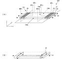
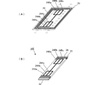
図2は第1の実施形態に係る磁性体アンテナ101の構成を示す図であり、(A)は磁性体アンテナ101で用いられるフレキシブル基板の展開状態の斜視図、(B)は磁性体アンテナ101で用いられる磁性体コア及びフレキシブル基板の折り曲げた状態での斜視図、(C)は磁性体アンテナ101の斜視図である。
<< First Embodiment >>
2A and 2B are diagrams showing a configuration of the
図2に示すように、磁性体アンテナ101は、コイル導体24を形成したフレキシブル基板23と磁性体コア22とを備えている。フレキシブル基板23には矩形渦巻状のコイル導体24が形成されていて、コイル導体24の巻回中心部を導体開口部CWとして形成されている。すなわち、この導体開口部CWを取り囲むように渦巻状のコイル導体24が形成されている。
As shown in FIG. 2, the
図2(A)中の4本の二点鎖線は、このフレキシブル基板23の折り曲げ箇所を示している。図2に示すように、磁性体コア22に対して、フレキシブル基板23を二点鎖線に沿って折り曲げるとともに、このフレキシブル基板23で磁性体コア22の上面、左右の側面、及び下面の一部を包むように、フレキシブル基板23が配置される。
Four two-dot chain lines in FIG. 2A indicate the bent portions of the
磁性体コア22は矩形板状を成している。すなわち、磁性体コア22は平行な少なくとも2辺を備えた板状を成している。そして、フレキシブル基板23は、導体開口部CWの中心から離れたコイル導体24の2辺に沿って且つ磁性体コア22の2辺に沿って折り曲げられる。
The
このような構成により、磁性体コア22の主面に対して垂直に透過する磁束がコイル導体24のループ内を過ぎることになり、磁束の放射効率が高まる。また、コイル導体24の2辺が磁性体コア22の2辺の近傍に位置することになるので、コイル導体24が磁性体コア22の磁束透過面の一部を大きく塞ぐことがなく、アンテナの開口が広く確保できる。そのため、磁束の放射効率が高まり、アンテナの感度が高まって、通信可能な距離が延びる。
With such a configuration, the magnetic flux transmitted perpendicularly to the main surface of the
図2(A)に示したコイル導体24の両端部はコイル導体接続部であり、このコイル導体接続部が実装先の回路基板上の電極に導通するように磁性体アンテナ101が実装される。このようにして磁性体アンテナ101が回路基板に実装された状態で、上記回路基板に形成された導体(グランドパターン)と磁性体アンテナ101とによってアンテナ装置が構成されることになる。
Both ends of the
《第2の実施形態》
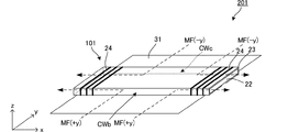
図3は第2の実施形態に係る磁性体アンテナ及びアンテナ装置の構成を示す図であり(A)はアンテナ装置の斜視図、(B)はその磁性体アンテナのコイル導体に流れる電流及び磁性体コアを透過する磁束について示している。
<< Second Embodiment >>
3A and 3B are diagrams showing the configuration of the magnetic antenna and the antenna device according to the second embodiment. FIG. 3A is a perspective view of the antenna device, and FIG. The magnetic flux passing through the core is shown.
図3(A)に示すように、金属板31に磁性体アンテナ101を実装することによってアンテナ装置201が構成される。金属板31は、例えば回路基板に形成された導体(グランドパターン)である。この金属板31が、本発明に係る「面状に広がる導体を有する板材」に相当する。
As shown in FIG. 3A, the
図3(A)において破線は主な磁束を表している。磁束を通さない金属板31の上に、磁性体アンテナ101が配置されることにより、金属板31に対して垂直方向からの磁束MFaがコイル導体の開口部CWaより入射して磁性体コア22の左右の端部から抜ける磁路が形成される。また、金属板31に対して垂直方向からの磁束MFbがコイル導体の開口部CWbより入射して磁性体コア22の左右の端部から抜ける磁路が形成される。同様に、金属板31に対して垂直方向からの磁束MFcがコイル導体の開口部CWcより入射して磁性体コア22の左右の端部から抜ける磁路が形成される。
In FIG. 3A, a broken line represents main magnetic flux. By disposing the
図3(B)は、磁性体コア22を透過する磁束とコイル導体24に流れる電流との関係を表している。但し、図の煩雑化を避けるためにコイル導体24はワンターンとして表している。この図に示すように、磁性体コア22を中央から両端面方向に磁束が透過すると、この磁束がコイル導体24のループ内を過ぎるため、起電力が発生する。したがって、図3(A)に示したように、磁束MFa,MFb,MFcが磁性体コア22を透過する際に、コイル導体24に起電力が発生する。
FIG. 3B shows the relationship between the magnetic flux passing through the
図4は、アンテナ装置201に対して、金属板の面に平行な向きに磁束が向く場合について、形成される磁路の様子を示している。金属板31の面に対して平行な+y方向に磁束MF(+y)が向く場合、図4中に破線で示すように、コイル導体24の開口部CWbより入射して磁性体コア22の左右の端部から抜ける磁路が形成される。同様に、−y方向に磁束MF(-y)が向く場合、図4中に破線で示すように、コイル導体24の開口部CWcより入射して磁性体コア22の左右の端部から抜ける磁路が形成される。
FIG. 4 shows the state of the magnetic path formed when the magnetic flux is directed to the
この磁路には方向性がないので、磁束がx方向に向く場合には、磁束は磁性体コア22の右又は左の端部から入射し、コイル導体24の開口部CWb,CWcより抜ける。
Since this magnetic path has no directionality, when the magnetic flux is directed in the x direction, the magnetic flux enters from the right or left end of the
なお、磁性体アンテナ101をy方向に直進する磁束やx方向に直進する磁束もあるが、コイル導体への起電力の誘起には寄与しない。 There are magnetic fluxes that move straight in the y direction and magnetic fluxes that move in the x direction, but they do not contribute to the induction of electromotive force in the coil conductor.
このようにして、磁束の向きは図3(A)に示したz方向だけでなく、x方向、y方向についても高い感度を有するアンテナ装置が得られる。 In this way, an antenna device having high sensitivity can be obtained not only in the z direction shown in FIG. 3A but also in the x and y directions.
なお、上記回路基板以外にも、例えば液晶表示パネルの裏面に配置されるシールド板に磁性体アンテナを配置して、このシール板と磁性体アンテナとによってアンテナ装置を構成してもよい。 In addition to the circuit board, for example, a magnetic antenna may be disposed on a shield plate disposed on the back surface of the liquid crystal display panel, and the antenna device may be configured by the seal plate and the magnetic antenna.
《第3の実施形態》
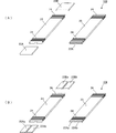
図5は第3の実施形態に係る磁性体アンテナ102の構成を示す図であり、(A)は磁性体アンテナ102で用いるフレキシブル基板の展開図、(B)は磁性体アンテナ102で用いる磁性体コア22の斜視図、(C)は磁性体アンテナ102の斜視図である。
<< Third Embodiment >>
5A and 5B are diagrams showing the configuration of the
この第3の実施形態に係る磁性体アンテナ102では、フレキシブル基板23に2つの矩形渦巻き状のコイル導体24a,24bが形成されている。両者の巻回方向は互いに逆であり、フレキシブル基板23上で直列接続されている。矩形渦巻き状を成すコイル導体24a,24bのそれぞれの内終端にはコイル導体の接続部25a,25bが形成されている。
In the
図5(A)中の4本の二点鎖線は、このフレキシブル基板23の折り曲げ箇所を示している。フレキシブル基板23は、導体開口部CWa,CWbの中心から離れたコイル導体24a,24bの2辺に沿って、且つ磁性体コア22の2辺に沿って折り曲げられる。
Four two-dot chain lines in FIG. 5A indicate the bent portions of the
このような構成により、磁性体コア22の主面に対して垂直に透過する磁束がコイル導体24のループ内を過ぎることになり、磁束の放射効率が高まる。また、コイル導体24の2辺が磁性体コア22の2辺の近傍に位置することになるので、コイル導体24が磁性体コア22の磁束透過面の一部を大きく塞ぐことがなく、アンテナの開口が広く確保できる。そのため、磁束の放射効率が高まり、アンテナの感度が高まって、通信可能な距離が延びる。
With such a configuration, the magnetic flux transmitted perpendicularly to the main surface of the
また、この磁性体アンテナ102を第2の実施形態で図3に示したように金属板に近接させた場合にも、図3(A)や図4に示した磁路が形成され、第2の実施形態の場合と同様の効果を奏する。
Further, when this
図5に示した例では、2つのコイル導体24a,24bの接続パターンが簡素なものとなり、配線同士の絶縁が不要であるので、実装先の回路基板上で直列接続する必要もなくなる。2つのコイル導体を並列接続する場合や実装先の回路基板上で直列接続または並列接続する場合には、2つのコイル導体のループを過ぎる磁束によってそれぞれ生じる起電力の向きが加算される方向に接続すればよいので、2つのコイル導体の巻回方向は同方向・逆方向のいずれでも構成できる。
In the example shown in FIG. 5, since the connection pattern of the two
このように2つのコイル導体を用いれば、2つのコイル導体の接続方法(直列/並列)を適宜選ぶことにより、アンテナのインピータンスを広範囲に亘って設計できるようになる。 If two coil conductors are used in this way, the antenna impedance can be designed over a wide range by appropriately selecting the connection method (series / parallel) of the two coil conductors.
なお、各実施形態では、フレキシブル基板を4本のラインで90度に折り曲げて磁性体コアの三面を包むように配置したが、フレキシブル基板は90度に折り曲げる必要はなく、湾曲させて磁性体コアに巻き付けるように配置してもよい。 In each embodiment, the flexible substrate is bent at 90 degrees by four lines so as to wrap around the three surfaces of the magnetic core. You may arrange | position so that it may wind.
《第4の実施形態》
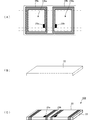
図6は第4の実施形態に係る磁性体アンテナ103,104の構成を示す図であり、(A)は磁性体アンテナ103の斜視図及びその分解斜視図である。また、(A)は磁性体アンテナ103の斜視図及びその分解斜視図である。
<< Fourth Embodiment >>
FIG. 6 is a diagram showing the configuration of the
図6(A)に示すように、磁性体アンテナ103は、コイル導体24が形成されたフレキシブル基板23と2つの磁性体コア22A,22Bとを備えている。この2つのコア22A,22Bはフレキシブル基板23のコイル導体24の巻回位置に配置される。フレキシブル基板23及びそれに対するコイル導体24の形成パターンは図2に示したものと同様である。
As shown in FIG. 6A, the
このように磁性体コアを2つに分割するとともに、それぞれを必要な位置にのみ配置することにより、磁性体コア22A,22Bは、磁路としての作用を保ったまま、その耐衝撃性が高まる。また、磁性体コアの占有体積が削減され軽量化が図れる。
As described above, by dividing the magnetic core into two parts and arranging them only at necessary positions, the
図6(B)に示す例は、フレキシブル基板23の両端部に配置する磁性体コアが更に2分割されたものである。ここで、一方端の磁性体コア22Aa,22Abは一定の微小間隙を設けて並設される。他方端の磁性体コア22Ba,22Bbも一定の微小間隙を設けて並設される。
In the example shown in FIG. 6B, the magnetic cores arranged at both ends of the
このように磁性体コアを全体で4つに分割することにより、各磁性体コア22Aa,22Ab,22Ba,22Bbの耐衝撃性がさらに高まる。
なお、機器の落下等に起因する衝撃によって、並設されている磁性体コア22Aa,22Ab同士、及び磁性体コア22Ba,22Bb同士が当接しないように、磁性体コア22Aa−22Ab間、及び22Ba−22Bb間にそれぞれ軟質のスペーサを介在させてもよい。また、各磁性体コア22Aa,22Ab,22Ba,22Bbをフレキシブル基板23または実装先の回路基板に接着してもよい。
Thus, by dividing the magnetic core into four in total, the impact resistance of each magnetic core 22Aa, 22Ab, 22Ba, 22Bb is further enhanced.
The magnetic cores 22Aa and 22Ab and the magnetic cores 22Ba and 22Bb are not in contact with each other due to an impact caused by a fall of the device, and between the magnetic cores 22Aa and 22Ab and 22Ba. A soft spacer may be interposed between -22Bb. Further, the magnetic cores 22Aa, 22Ab, 22Ba, and 22Bb may be bonded to the
《第5の実施形態》
図7は第5の実施形態に係る磁性体アンテナ105の構成を示す図であり、(A)は磁性体アンテナ105で用いるフレキシブル基板の展開状態の斜視図、(B)は磁性体アンテナ105の斜視図である。
<< Fifth Embodiment >>
7A and 7B are diagrams showing a configuration of the
図7に示すように、磁性体アンテナ105は、コイル導体24を形成したフレキシブル基板23と磁性体コア22とを備えている。フレキシブル基板23には全体的には矩形渦巻状のコイル導体24が形成されていて、その一部にインダクタンス調整用のコイル導体パターン24Aa,24Ab,24Ac,24Ba,24Bb,24Bcが形成されている。
As shown in FIG. 7, the
図7(A)中の4本の二点鎖線は、このフレキシブル基板23の折り曲げ箇所を示している。図7に示すように、磁性体コア22に対して、フレキシブル基板23を二点鎖線に沿って折り曲げるとともに、このフレキシブル基板23で磁性体コア22の上面、左右の側面、及び下面の一部を包むように、フレキシブル基板23が配置される。
Four two-dot chain lines in FIG. 7A indicate the bent portions of the
このような構成により、インダクタンス調整用のコイル導体パターン24Aa,24Ab,24Ac,24Ba,24Bb,24Bcのうち所定の一つまたは複数のコイル導体パターンをレーザトリミングすることにより、磁性体アンテナ105のインダクタンスを所定値に定めることが可能となる。
With such a configuration, the inductance of the
22…磁性体コア
23…フレキシブル基板
24…コイル導体
24a,24b…コイル導体
25a,25b…接続部
31…金属板
101〜105…磁性体アンテナ
201…アンテナ装置
CW…導体開口部
MFa…磁束
MF(+y),MF(-y)…磁束
DESCRIPTION OF
Claims (4)
前記磁性体コアは平行な少なくとも2辺を備えた板状を成し、
前記コイル導体は、巻回中心部を導体開口部とする、平行な少なくとも2辺を備える矩形渦巻き状を成し、
前記フレキシブル基板は、前記導体開口部の中心から離れた前記コイル導体の2辺に沿って且つ前記磁性体コアの前記2辺に沿って折り曲げられたことを特徴とする磁性体アンテナ。 In the magnetic antenna in which the flexible substrate on which the coil conductor is formed is wound along the surface of the magnetic core,
The magnetic core has a plate shape with at least two parallel sides,
The coil conductor has a rectangular spiral shape having at least two sides parallel to each other with the winding center as a conductor opening.
The magnetic antenna according to claim 1, wherein the flexible substrate is bent along two sides of the coil conductor away from a center of the conductor opening and along the two sides of the magnetic core.
Priority Applications (3)
| Application Number | Priority Date | Filing Date | Title |
|---|---|---|---|
| JP2008220739A JP4957683B2 (en) | 2008-08-29 | 2008-08-29 | Antenna device |
| US12/507,272 US8294629B2 (en) | 2008-08-29 | 2009-07-22 | Magnetic antenna and antenna device |
| DE102009038824A DE102009038824A1 (en) | 2008-08-29 | 2009-08-25 | Magnetic antenna and antenna device |
Applications Claiming Priority (1)
| Application Number | Priority Date | Filing Date | Title |
|---|---|---|---|
| JP2008220739A JP4957683B2 (en) | 2008-08-29 | 2008-08-29 | Antenna device |
Publications (2)
| Publication Number | Publication Date |
|---|---|
| JP2010056982A true JP2010056982A (en) | 2010-03-11 |
| JP4957683B2 JP4957683B2 (en) | 2012-06-20 |
Family
ID=41606380
Family Applications (1)
| Application Number | Title | Priority Date | Filing Date |
|---|---|---|---|
| JP2008220739A Active JP4957683B2 (en) | 2008-08-29 | 2008-08-29 | Antenna device |
Country Status (3)
| Country | Link |
|---|---|
| US (1) | US8294629B2 (en) |
| JP (1) | JP4957683B2 (en) |
| DE (1) | DE102009038824A1 (en) |
Cited By (4)
| Publication number | Priority date | Publication date | Assignee | Title |
|---|---|---|---|---|
| JP2014103749A (en) * | 2012-11-19 | 2014-06-05 | Toshiba Corp | Wireless power transmission device |
| WO2014142345A1 (en) | 2013-03-15 | 2014-09-18 | Ricoh Company, Ltd. | Antenna device |
| US10396463B2 (en) | 2015-11-19 | 2019-08-27 | Ricoh Company, Ltd. | Antenna device |
| US10522910B2 (en) | 2017-01-10 | 2019-12-31 | Ricoh Company, Ltd. | Antenna device, communication device, and method for producing antenna device |
Families Citing this family (22)
| Publication number | Priority date | Publication date | Assignee | Title |
|---|---|---|---|---|
| US9190711B2 (en) * | 2010-07-28 | 2015-11-17 | Panasonic Intellectual Property Management Co., Ltd. | Antenna device and communication apparatus including the same |
| WO2012144482A1 (en) * | 2011-04-18 | 2012-10-26 | 株式会社村田製作所 | Antenna device and communication terminal device |
| WO2012174634A1 (en) * | 2011-06-20 | 2012-12-27 | Research In Motion Limited | Near field communication antenna |
| CN103348533B (en) * | 2011-08-25 | 2015-04-01 | 株式会社村田制作所 | Antenna device |
| US8669909B2 (en) | 2011-11-30 | 2014-03-11 | Panasonic Corporation | Antenna, antenna apparatus, and communication apparatus |
| US9520917B2 (en) | 2012-02-13 | 2016-12-13 | Intel Corporation | Antenna configuration to facilitate near field coupling |
| JP5639606B2 (en) * | 2012-02-27 | 2014-12-10 | 三智商事株式会社 | Wireless IC tag |
| WO2014085659A1 (en) * | 2012-11-28 | 2014-06-05 | The Board Of Trustees Of The University Of Alabama For And On Behalf Of The University Of Alabama | Dual-polarized magnetic antennas |
| US10505269B2 (en) | 2013-04-28 | 2019-12-10 | The Board Of Trustees Of The University Of Alabama For And On Behalf Of The University Of Alabama | Magnetic antenna structures |
| WO2015098795A1 (en) * | 2013-12-26 | 2015-07-02 | 株式会社村田製作所 | Antenna device and electronic appliance |
| WO2016056736A1 (en) | 2014-10-10 | 2016-04-14 | 에이큐 주식회사 | Near field communication antenna and smart phone having antenna |
| CN104485509A (en) * | 2014-12-19 | 2015-04-01 | 周祥 | Space division antenna for RFID system of supermarket and warehousing |
| US10461398B2 (en) * | 2015-04-03 | 2019-10-29 | Fit Pay, Inc. | Accordion antenna structure with simplified construction |
| JP6627252B2 (en) * | 2015-04-28 | 2020-01-08 | Tdk株式会社 | Antenna device |
| US10522912B2 (en) * | 2016-05-12 | 2019-12-31 | Tdk Corporation | Antenna device and mobile wireless device provided with the same |
| US10547112B2 (en) | 2016-09-02 | 2020-01-28 | AQ Corporation | Smartphone antenna in flexible PCB |
| US10074891B2 (en) | 2016-09-02 | 2018-09-11 | AQ Corporation | Smartphone antenna in flexible PCB |
| USD850424S1 (en) | 2016-12-14 | 2019-06-04 | AQ Corporation | Flexible PCB dual antenna module for use in smartphone |
| US10003120B2 (en) | 2016-09-02 | 2018-06-19 | AQ Corporation | Smartphone antenna in flexible PCB |
| US11528058B2 (en) * | 2016-09-06 | 2022-12-13 | Apple Inc. | Inductive charging coil configuration for wearable electronic devices |
| US11102886B2 (en) * | 2019-09-30 | 2021-08-24 | Samsung Electro-Mechanics Co., Ltd. | Printed circuit board |
| US11303011B2 (en) | 2019-11-27 | 2022-04-12 | AQ Corporation | Smartphone antenna in flexible PCB |
Citations (6)
| Publication number | Priority date | Publication date | Assignee | Title |
|---|---|---|---|---|
| JP2003022912A (en) * | 2001-03-30 | 2003-01-24 | Mitsubishi Materials Corp | Antenna coil, identification tag using the same, reader- writer apparatus, reader and writer |
| JP2005318329A (en) * | 2004-04-28 | 2005-11-10 | Sharp Corp | Antenna mounting member and communication terminal |
| JP2005333244A (en) * | 2004-05-18 | 2005-12-02 | Mitsubishi Electric Corp | Mobile telephone set |
| JP2008035464A (en) * | 2006-03-13 | 2008-02-14 | Murata Mfg Co Ltd | Portable electronic device |
| JP2008035459A (en) * | 2006-07-07 | 2008-02-14 | Murata Mfg Co Ltd | Antenna device |
| JP2008048376A (en) * | 2006-07-07 | 2008-02-28 | Murata Mfg Co Ltd | Antenna coil to be mounted on circuit board and antenna device |
Family Cites Families (1)
| Publication number | Priority date | Publication date | Assignee | Title |
|---|---|---|---|---|
| JP4893135B2 (en) * | 2006-07-20 | 2012-03-07 | 株式会社村田製作所 | Magnetic material antenna and antenna device |
-
2008
- 2008-08-29 JP JP2008220739A patent/JP4957683B2/en active Active
-
2009
- 2009-07-22 US US12/507,272 patent/US8294629B2/en active Active
- 2009-08-25 DE DE102009038824A patent/DE102009038824A1/en not_active Withdrawn
Patent Citations (6)
| Publication number | Priority date | Publication date | Assignee | Title |
|---|---|---|---|---|
| JP2003022912A (en) * | 2001-03-30 | 2003-01-24 | Mitsubishi Materials Corp | Antenna coil, identification tag using the same, reader- writer apparatus, reader and writer |
| JP2005318329A (en) * | 2004-04-28 | 2005-11-10 | Sharp Corp | Antenna mounting member and communication terminal |
| JP2005333244A (en) * | 2004-05-18 | 2005-12-02 | Mitsubishi Electric Corp | Mobile telephone set |
| JP2008035464A (en) * | 2006-03-13 | 2008-02-14 | Murata Mfg Co Ltd | Portable electronic device |
| JP2008035459A (en) * | 2006-07-07 | 2008-02-14 | Murata Mfg Co Ltd | Antenna device |
| JP2008048376A (en) * | 2006-07-07 | 2008-02-28 | Murata Mfg Co Ltd | Antenna coil to be mounted on circuit board and antenna device |
Cited By (5)
| Publication number | Priority date | Publication date | Assignee | Title |
|---|---|---|---|---|
| JP2014103749A (en) * | 2012-11-19 | 2014-06-05 | Toshiba Corp | Wireless power transmission device |
| WO2014142345A1 (en) | 2013-03-15 | 2014-09-18 | Ricoh Company, Ltd. | Antenna device |
| US10164337B2 (en) | 2013-03-15 | 2018-12-25 | Ricoh Company, Ltd. | Antenna device |
| US10396463B2 (en) | 2015-11-19 | 2019-08-27 | Ricoh Company, Ltd. | Antenna device |
| US10522910B2 (en) | 2017-01-10 | 2019-12-31 | Ricoh Company, Ltd. | Antenna device, communication device, and method for producing antenna device |
Also Published As
| Publication number | Publication date |
|---|---|
| US8294629B2 (en) | 2012-10-23 |
| US20100053014A1 (en) | 2010-03-04 |
| JP4957683B2 (en) | 2012-06-20 |
| DE102009038824A1 (en) | 2010-03-04 |
Similar Documents
| Publication | Publication Date | Title |
|---|---|---|
| JP4957683B2 (en) | Antenna device | |
| JP4905506B2 (en) | Antenna device | |
| JP4131294B2 (en) | Antenna coil and antenna device | |
| US8354971B2 (en) | Antenna device | |
| JP5510443B2 (en) | Antenna device and portable terminal | |
| JP4893631B2 (en) | Antenna device | |
| EP2296228B1 (en) | Antenna, antenna unit, and communication device using them | |
| JP5287289B2 (en) | Antenna device | |
| JP2016174417A (en) | Antenna device and communication terminal device | |
| JP2010245776A (en) | Antenna | |
| JP2010154007A (en) | Magnetic antenna and antenna device | |
| CN103620868A (en) | Antenna apparatus and communication terminal apparatus | |
| JP5510547B2 (en) | Antenna device and communication terminal device | |
| JP6589403B2 (en) | Antenna device and coil component used therefor | |
| JP5321236B2 (en) | Magnetic material antenna and antenna device | |
| JP4711010B2 (en) | Antenna device | |
| JP2011234174A (en) | Antenna device | |
| JP5093412B2 (en) | Antenna coil and antenna device | |
| JP5293369B2 (en) | Magnetic material antenna and antenna device | |
| JP4807463B2 (en) | Antenna device | |
| JP2009206975A (en) | Magnetic body antenna, and antenna apparatus | |
| JP5077477B2 (en) | Antenna and mobile phone terminal |
Legal Events
| Date | Code | Title | Description |
|---|---|---|---|
| A621 | Written request for application examination |
Free format text: JAPANESE INTERMEDIATE CODE: A621 Effective date: 20101117 |
|
| A977 | Report on retrieval |
Free format text: JAPANESE INTERMEDIATE CODE: A971007 Effective date: 20110804 |
|
| A131 | Notification of reasons for refusal |
Free format text: JAPANESE INTERMEDIATE CODE: A131 Effective date: 20111129 |
|
| A521 | Request for written amendment filed |
Free format text: JAPANESE INTERMEDIATE CODE: A523 Effective date: 20120130 |
|
| RD02 | Notification of acceptance of power of attorney |
Free format text: JAPANESE INTERMEDIATE CODE: A7422 Effective date: 20120130 |
|
| TRDD | Decision of grant or rejection written | ||
| A01 | Written decision to grant a patent or to grant a registration (utility model) |
Free format text: JAPANESE INTERMEDIATE CODE: A01 Effective date: 20120221 |
|
| A01 | Written decision to grant a patent or to grant a registration (utility model) |
Free format text: JAPANESE INTERMEDIATE CODE: A01 |
|
| A61 | First payment of annual fees (during grant procedure) |
Free format text: JAPANESE INTERMEDIATE CODE: A61 Effective date: 20120305 |
|
| FPAY | Renewal fee payment (event date is renewal date of database) |
Free format text: PAYMENT UNTIL: 20150330 Year of fee payment: 3 |
|
| R150 | Certificate of patent or registration of utility model |
Ref document number: 4957683 Country of ref document: JP Free format text: JAPANESE INTERMEDIATE CODE: R150 Free format text: JAPANESE INTERMEDIATE CODE: R150 |