JP2010055200A - Server explicit selection type reverse proxy device, data relay method therefor, and program thereof - Google Patents
Server explicit selection type reverse proxy device, data relay method therefor, and program thereof Download PDFInfo
- Publication number
- JP2010055200A JP2010055200A JP2008217035A JP2008217035A JP2010055200A JP 2010055200 A JP2010055200 A JP 2010055200A JP 2008217035 A JP2008217035 A JP 2008217035A JP 2008217035 A JP2008217035 A JP 2008217035A JP 2010055200 A JP2010055200 A JP 2010055200A
- Authority
- JP
- Japan
- Prior art keywords
- identifier
- network
- destination
- host
- reverse proxy
- Prior art date
- Legal status (The legal status is an assumption and is not a legal conclusion. Google has not performed a legal analysis and makes no representation as to the accuracy of the status listed.)
- Granted
Links
Images


Abstract
Description
本発明は、WWW(World Wide Web)に代表されるようなハイパーテキスト転送プロトコルデータでデータ通信を行うインターネット通信技術を構成する技術である。特に、インターネット通信分野のうち、企業内に閉じたイントラネットから、企業外のVPN(Virtual Private Network)にセキュアにアクセスするためのVPN通信分野に属する。 The present invention is a technology that constitutes an Internet communication technology for performing data communication using hypertext transfer protocol data represented by WWW (World Wide Web). In particular, the Internet communication field belongs to the VPN communication field for securely accessing a VPN (Virtual Private Network) outside the company from an intranet closed within the company.
従来のリバースプロキシー装置は、ユーザとwebサーバ間でのハイパーテキスト転送プロトコルデータによる中継装置に位置づけられ、主としてapacheやsquidと呼ばれるプログラムを用いて実現されている。例えば、ユーザを配置した企業のイントラネット(第一のネットワーク)と、Webサーバを配置したアプリケーションサービスプロバイダのネットワーク(第二のネットワーク)を相互接続するために有効である。このようなネットワーク構成において、ユーザは、宛先統一資源位置指定子のホスト識別子にリバースプロキシー装置の識別子を記述して、リバースプロキシー装置宛にデータを送信する。リバースプロキシー装置は、自宛のホスト識別子を、実際のwebサーバのホスト識別子に変換して、データをwebサーバ宛に転送する。この際、データ中継毎に異なるwebサーバのホスト識別子に変換してデータ転送することで、複数のwebサーバ間での負荷分散が可能となる。 A conventional reverse proxy device is positioned as a relay device using hypertext transfer protocol data between a user and a web server, and is mainly realized by using a program called apache or squid. For example, it is effective for interconnecting a company intranet (first network) in which a user is arranged with an application service provider network (second network) in which a web server is arranged. In such a network configuration, the user describes the identifier of the reverse proxy device in the host identifier of the destination unified resource location specifier, and transmits data to the reverse proxy device. The reverse proxy device converts the host identifier addressed to itself into the host identifier of the actual web server, and transfers the data to the web server. At this time, by converting the data to a different web server host identifier for each data relay and transferring the data, it is possible to distribute the load among the plurality of web servers.
リバースプロキシー装置について記載された文献としては、例えば非特許文献1、特許文献1がある。
For example, Non-Patent
従来のリバースプロキシー装置では、転送先のwebサーバを複数指定することが可能であった。しかし、ユーザは、リバースプロキシー装置経由でハイパーテキスト転送プロトコルデータの中継を行う場合、リバースプロキシー装置の識別子をホスト識別子とした統一資源位置指定子を宛先として指定することしかできないため、これらのwebサーバを明示的に指定できなかった。このため、同様のコンテンツを有したwebサーバ間での負荷分散は行えても、Webサーバ毎に異なるコンテンツを配備して、要求されるコンテンツに応じて、Webサーバを選択することができなかった。そこで、本発明では、リバースプロキシー装置経由の通信において、送信ユーザが宛先webサーバを明示的に指定した通信を実現することを解決すべき課題とする。 In the conventional reverse proxy device, it is possible to specify a plurality of transfer destination web servers. However, when relaying hypertext transfer protocol data via a reverse proxy device, a user can only specify a uniform resource location specifier with the identifier of the reverse proxy device as a host identifier as a destination. Could not be specified explicitly. For this reason, even if load balancing can be performed among web servers having similar contents, it is not possible to deploy different contents for each web server and select the web server according to the requested contents. . Therefore, in the present invention, it is an object to be solved to realize communication in which a transmission user explicitly designates a destination web server in communication via a reverse proxy device.
本明細書において開示される発明のうち、代表的なものの概要を簡単に説明すれば、以下のとおりである。 Of the inventions disclosed in this specification, the outline of typical ones will be briefly described as follows.
請求項1の発明では、リバースプロキシー装置が、宛先統一資源位置指定子の変換の際に、ディレクトリ識別子の内容に応じて異なるホスト識別子を特定し変換し、ディレクトリ識別子の内容の一部を削除して、ディレクトリ識別子を再構成することで変換することを特徴とする。 In the first aspect of the invention, the reverse proxy device specifies and converts a different host identifier according to the contents of the directory identifier and converts a part of the contents of the directory identifier when converting the destination uniform resource locator. Thus, the directory identifier is converted by reconstructing.
また、請求項2の発明では、リバースプロキシー装置が、さらに、宛先統一資源位置指定子の変換の際に、ディレクトリ識別子の一部の領域を、宛先ホストの識別部と解釈して変換することを特徴とする。
In the invention of
一方、請求項3の発明では、リバースプロキシー装置が、ディレクトリ識別子の一部の領域を、ユーザ識別子の識別部と解釈して予め決められたユーザ識別子を有しない場合に、転送先のホストへのハイパーテキスト転送プロトコルデータの中継を行わないことを特徴とする。 On the other hand, in the third aspect of the invention, when the reverse proxy device interprets a part of the directory identifier as a user identifier identifier and does not have a predetermined user identifier, The hypertext transfer protocol data is not relayed.
請求項4の発明では、送信元ユーザのユーザ識別子と宛先ネットワークの識別子の組と、その組に対応する転送または廃棄のいずれかの処理内容を登録する認証テーブルと、ハイパーテキスト転送プロトコルデータの転送または廃棄の判断を行う認証手段と、を備え、前記認証手段は、受信したハイパーテキスト転送プロトコルデータのディレクトリ識別子に記述されたユーザ識別子と宛先ネットワークの識別子から、前記認証テーブルを参照して、転送または廃棄の判断を行う、ことを特徴とする。 In the invention of claim 4, a pair of a user identifier of a transmission source user and an identifier of a destination network, an authentication table for registering processing contents of either transfer or discard corresponding to the pair, and transfer of hypertext transfer protocol data Or an authentication unit that determines discarding, and the authentication unit refers to the authentication table based on the user identifier described in the directory identifier of the received hypertext transfer protocol data and the identifier of the destination network. Or it is characterized by making a judgment of disposal.
さらに、請求項5の発明では、リバースプロキシー装置が、それぞれ、統一資源位置指定子とインターネットプロトコルアドレスの体系が異なる2つのネットワークを収容するインタフェース機能を有することを特徴とする。 Further, the invention of claim 5 is characterized in that each reverse proxy device has an interface function for accommodating two networks having different unified resource locator and Internet protocol address systems.
請求項6の発明では、第一のネットワークで定義されるホスト識別子と第二のネットワークで定義されるホスト識別子の対応関係を登録する変換テーブルを備え、前記識別子変換手段は、第一のネットワークから受信したハイパーテキスト転送プロトコルデータの宛先統一資源位置指定子のディレクトリ識別子に記述された第一のネットワークで定義されるホスト識別子から、前記変換テーブルを参照して、第二のネットワークで定義されるホスト識別子を得て、これを宛先ホスト識別子とする、ことを特徴とする。 The invention according to claim 6 further comprises a conversion table for registering a correspondence relationship between the host identifier defined in the first network and the host identifier defined in the second network, and the identifier conversion means includes: The host defined in the second network by referring to the conversion table from the host identifier defined in the first network described in the directory identifier of the destination uniform resource locator of the received hypertext transfer protocol data An identifier is obtained, and this is used as a destination host identifier.
請求項7の発明では、変換後のディレクトリ識別子は、受信したハイパーテキスト転送プロトコルデータの宛先統一資源位置指定子のディレクトリ識別子に記述された宛先ホスト内でのディレクトリ識別子であることを特徴とする。 The directory identifier after conversion is a directory identifier in the destination host described in the directory identifier of the destination unified resource location specifier of the received hypertext transfer protocol data.
さらに、請求項8の発明は、請求項1の発明の内容を実現するデータ中継方法であり、請求項9の発明は、請求項1ないし7のうちいずれか1項に記載のリバースプロキシー装置として、コンピュータを機能させるためのプログラムである。
Further, the invention of claim 8 is a data relay method for realizing the contents of the invention of
本発明により、単一のリバースプロキシー装置において、送信ユーザが宛先webサーバを明示的に指定して転送することが可能となる。 According to the present invention, in a single reverse proxy device, a transmission user can explicitly designate and transfer a destination web server.
本発明の構成例について説明する。 A configuration example of the present invention will be described.
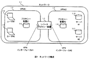
図1は、本発明のネットワーク構成を示す。1−1はネットワーク、1−2はVPN#1、1−3はVPN#2である。1−5は本発明の実施形態のサーバ明示選択型リバースプロキシー装置である。1−6はユーザ#1(より正確にはユーザ#1の端末)、1−7はユーザ#2(より正確にはユーザ#2の端末)である。1−8はプロキシー装置#1、1−9はプロキシー装置#2、1−10はサーバ端末#1、1−11はサーバ端末#2である。
FIG. 1 shows a network configuration of the present invention. 1-1 is a network, 1-2 is
この構成では、ネットワーク1−1がVPN#1とVPN#2で構成される。VPN#1はユーザ#1およびユーザ#2を収容する。また、VPN#1は中継装置として、プロキシー装置#1を有する。VPN#2はサーバ端末#1およびサーバ端末#2を収容する。また、VPN#2は中継装置として、プロキシー装置#2を有する。VPN#1とVPN#2は、サーバ明示選択型リバースプロキシー装置1−5を介して接続される。サーバ明示選択型リバースプロキシー装置1−5は、VPNインタフェース#1でVPN#1を収容し、VPNインタフェース#2でVPN#2を収容する。
In this configuration, the network 1-1 is configured with
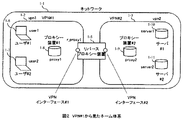
図2は、VPN#1から見たネーム体系を示す。VPN#1には、vpn1、VPN#2には、vpn2、ユーザ#1には、user1、ユーザ#2には、user2、サーバ端末#1には、server1、サーバ端末#2には、server2、プロキシー装置#1には、proxy1、プロキシー装置#2には、proxy2、サーバ明示選択型リバースプロキシー装置1−5にはr_proxy1とネームを付与する。
FIG. 2 shows the name system as seen from
図3は、VPN#2から見たネーム体系を示す。VPN#1には、vpn1、VPN#2には、vpn0、サーバ端末#1には、server0、サーバ端末#2には、server1、プロキシー装置#2には、proxy0、サーバ明示選択型リバースプロキシー装置1−5にはr_proxy0とネームを付与する。ここで、VPN#1から見たネーム体系とVPN#2から見たネーム体系は、異なることに注意する必要がある。
FIG. 3 shows the name system as seen from
図4は、サーバ明示選択型リバースプロキシー装置における宛先統一資源位置指定子の変換処理例である。この図は、上部に示す入力前の宛先統一資源位置指定子4−1と下部に示す出力後の宛先統一資源位置指定子4−2で構成される。 FIG. 4 shows an example of conversion processing of the destination unified resource location specifier in the server explicit selection type reverse proxy device. This figure is composed of a destination uniform resource location specifier 4-1 before input shown at the top and a destination uniform resource location specifier 4-2 after output shown at the bottom.
宛先統一資源位置指定子はアクセス手段識別子、ホスト識別子、ディレクトリ識別子で構成される。 The destination uniform resource location specifier includes an access means identifier, a host identifier, and a directory identifier.
入力前の宛先統一資源位置指定子4−1において、ホスト識別子は、送信元ユーザの帰属するVPNから見たサーバ明示選択型リバースプロキシー装置の識別子、送信元ユーザの帰属するVPNの識別子で構成され、ディレクトリ識別子は、送信元ユーザの帰属するVPNから見た送信元ユーザの識別子、送信元ユーザの帰属するVPNから見た宛先サーバの識別子、送信元ユーザの帰属するVPNから見た宛先サーバの帰属するVPNの識別子、宛先サーバ内でのディレクトリ識別子で構成される。 In the destination uniform resource location specifier 4-1 before input, the host identifier is composed of an identifier of the server explicit selection type reverse proxy device viewed from the VPN to which the transmission source user belongs, and an identifier of the VPN to which the transmission source user belongs. The directory identifier is the identifier of the transmission source user as seen from the VPN to which the transmission source user belongs, the identifier of the destination server as seen from the VPN to which the transmission source user belongs, and the attribution of the destination server as seen from the VPN to which the transmission source user belongs VPN identifiers and directory identifiers in the destination server.
この例では、入力前の宛先統一資源位置指定子4−1において、アクセス手段識別子として、http、送信元ユーザの帰属するVPNから見たサーバ明示選択型リバースプロキシー装置の識別子として、r_proxy1、送信元ユーザの帰属するVPNの識別子としてvpn1、送信元ユーザの帰属するVPNから見た送信元ユーザの識別子として、user1、送信元ユーザの帰属するVPNから見た宛先サーバの識別子として、server1、送信元ユーザの帰属するVPNから見た宛先サーバの帰属するVPNの識別子として、vpn2、宛先サーバ内でのディレクトリ識別子として、folder1/file1、が指定されている。 In this example, in the destination unified resource location specifier 4-1 before input, http is used as the access means identifier, and r_proxy1 is the sender explicit identifier of the server as seen from the VPN to which the sender belongs. Vpn1 as the VPN identifier to which the user belongs, user1 as the source user identifier as seen from the VPN to which the source user belongs, server1 as the destination server identifier as seen from the VPN to which the source user belongs, and source user Vpn2 is specified as the VPN identifier to which the destination server belongs as seen from the VPN to which the server belongs, and folder1 / file1 is specified as the directory identifier in the destination server.
また、出力後の宛先統一資源位置指定子4−2において、ホスト識別子は、宛先サーバの帰属するVPNから見た宛先サーバの識別子、宛先サーバの帰属するVPNから見た宛先サーバの帰属するVPNの識別子から構成され、ディレクトリ識別子は、宛先サーバ内でのディレクトリ識別子で構成される。 In the destination unified resource location specifier 4-2 after output, the host identifier is the identifier of the destination server viewed from the VPN to which the destination server belongs, and the VPN to which the destination server belongs from the VPN to which the destination server belongs. The directory identifier is composed of a directory identifier in the destination server.
この例では、出力後の宛先統一資源位置指定子4−2において、アクセス手段識別子として、http、宛先サーバの帰属するVPNから見た宛先サーバの識別子として、server0、宛先サーバの帰属するVPNから見た宛先サーバの帰属するVPNの識別子として、vpn0、宛先サーバ内でのディレクトリ識別子として、folder1/file1、が指定されている。 In this example, in the destination unified resource location specifier 4-2 after output, the access means identifier is http, the destination server identifier as seen from the VPN to which the destination server belongs, server0, and the destination server as seen from the VPN to which the destination server belongs. In addition, vpn0 is designated as the VPN identifier to which the destination server belongs, and folder1 / file1 is designated as the directory identifier in the destination server.
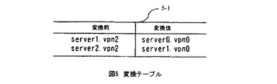
図5に、変換テーブル5−1を示す。この変換テーブル5−1では、変換前としての送信元ユーザの帰属するVPNから見た宛先サーバの識別子と送信元ユーザの帰属するVPNから見た宛先サーバの帰属するVPNの識別子の組から、変換後としての宛先サーバの帰属するVPNから見た宛先サーバの識別子と宛先サーバの帰属するVPNから見た宛先サーバの帰属するVPNの識別子の組が導かれる。 FIG. 5 shows the conversion table 5-1. In this conversion table 5-1, a conversion is made from a pair of the identifier of the destination server seen from the VPN to which the transmission source user belongs and the VPN identifier to which the destination server belongs seen from the VPN to which the transmission source user belongs. A set of the identifier of the destination server seen from the VPN to which the destination server belongs and the identifier of the VPN to which the destination server belongs seen from the VPN to which the destination server belongs is derived.
例えば、変換前のserver1.vpn2からは、変換後のserver0.vpn0が、変換前のserver2.vpn2からは、変換後のserver1.vpn0が導かれる。ここで「.」は識別子同士の境界点を示す記号である。 For example, server1. From vpn2, converted server0. If vpn0 is server2. From vpn2, converted server1. vpn0 is derived. Here, “.” Is a symbol indicating a boundary point between identifiers.
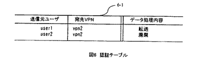
図6に、認証テーブル6−1を示す。この認証テーブル6−1では、送信元ユーザの帰属するVPNから見た送信元ユーザの識別子と送信元ユーザの帰属するVPNから見た宛先VPNの識別子の組から、データ処理内容として「転送」あるいは「廃棄」が導かれる。 FIG. 6 shows the authentication table 6-1. In this authentication table 6-1, “transfer” or “transfer” or “data transfer” is selected as the data processing content from the set of the identifier of the transmission source user viewed from the VPN to which the transmission source user belongs and the identifier of the destination VPN viewed from the VPN to which the transmission source user belongs. “Discard” is led.
例えば、user1とvpn2の組からは「転送」が、user2とvpn2の組からは「廃棄」が、が導かれる。 For example, “transfer” is derived from the set of user1 and vpn2, and “discard” is derived from the set of user2 and vpn2.
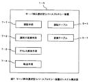
図7に、本発明の実施形態のサーバ明示選択型リバースプロキシー装置1−5のシステム構成図を示す。 FIG. 7 is a system configuration diagram of the server explicit selection type reverse proxy device 1-5 according to the embodiment of this invention.
7−1は、受信したハイパーテキスト転送プロトコルデータのディレクトリ識別子に記述されたユーザ識別子と宛先ネットワークの識別子から、認証テーブル6−1を参照して、転送または廃棄の判断を行う認証手段である。7−2は、VPN#1から受信したハイパーテキスト転送プロトコルデータに記述された、ホスト識別子とディレクトリ識別子を含んで構成される宛先統一資源位置指定子に対して、ディレクトリ識別子の内容に応じて宛先ホスト識別子を特定し、前記宛先統一資源位置指定子に記述されたホスト識別子を、特定した宛先ホストに変換すると共に、前記宛先統一資源位置指定子に記述されたディレクトリ識別子を、該ディレクトリ識別子の内容の一部を削除したディレクトリ識別子に変換する識別子変換手段である。7−3は、アドレス解決を行うアドレス解決手段である。7−4は、ホスト識別子とディレクトリ識別子が変換された宛先統一資源位置指定子が記述されたハイパーテキスト転送プロトコルを、VPN#2に転送する転送手段である。
Reference numeral 7-1 denotes an authentication unit that refers to the authentication table 6-1 and determines whether to transfer or discard the user identifier described in the directory identifier of the received hypertext transfer protocol data and the identifier of the destination network. 7-2 is a destination according to the contents of the directory identifier for the destination uniform resource location specifier including the host identifier and the directory identifier described in the hypertext transfer protocol data received from
6−1は、図6に示す認証テーブルである。認証テーブル6−1には、送信元ユーザのユーザ識別子と宛先ネットワークの識別子の組と、その組に対応する転送または廃棄のいずれかの処理内容が登録される。5−1は、図5に示す変換テーブルである。変換テーブルには、VPN#1で定義されるホスト識別子とVPN#2で定義されるホスト識別子の対応関係が登録される。
6-1 is an authentication table shown in FIG. In the authentication table 6-1, a set of the user identifier of the transmission source user and the identifier of the destination network and the processing contents of either transfer or discard corresponding to the set are registered. 5-1 is a conversion table shown in FIG. In the conversion table, the correspondence between the host identifier defined by
識別子変換手段7−2は、VPN#1から受信したハイパーテキスト転送プロトコルデータの宛先統一資源位置指定子のディレクトリ識別子に記述されたVPN#1で定義されるホスト識別子から、変換テーブル5−1を参照して、VPN#2で定義されるホスト識別子を得て、これを宛先ホスト識別子とする。
The identifier conversion unit 7-2 obtains the conversion table 5-1 from the host identifier defined by
アドレス解決手段7−3は、ハイパーテキスト転送プロトコルデータをVPNインタフェース#2からVPN#2に送信する場合は、図示していないVPN#2におけるDNS(Domain Name System)サーバを用いて、VPN#2で定義される宛先統一資源位置指定子のホスト識別子から、VPN#2で定義される宛先インターネットプロトコルアドレスを解決し、ハイパーテキスト転送プロトコルデータをVPNインタフェース#1からVPN#1に送信する場合は、図示していないVPN#1におけるDNSサーバを用いて、VPN#1で定義される宛先統一資源位置指定子のホスト識別子から、VPN#1で定義される宛先インターネットプロトコルアドレスを解決する。なお、本実施形態ではDNSサーバを用いてアドレス解決を行っているが、その他の方法を用いてもよい。
When the hypertext transfer protocol data is transmitted from the
上述の構成における動作例について説明する。 An operation example in the above configuration will be described.
ここでは、図1において、ユーザ#1から、サーバ端末#1のfolder1/file1へハイパーテキスト転送プロトコルレイヤでアクセスする例について説明する。
Here, an example in which the
ユーザ#1は、図4に示す宛先統一資源位置指定子http://r_proxy1.vpn1/user1/server1.vpn2/folder1/file1を付与したハイパーテキスト転送プロトコルデータを送信する。この際、プロキシーとして、プロキシー装置(proxy1)が付与されていたとすると、送信データはプロキシー装置#1へ到達する。
The
プロキシー装置#1は、受信したハイパーテキスト転送プロトコルデータの宛先統一資源位置指定子を参照し、宛先のホスト識別子として、サーバ明示選択型リバースプロキシー装置1−5のホスト識別子r_proxy1を特定するため、これをサーバ明示選択型リバースプロキシー装置1−5へ転送する。
The
サーバ明示選択型リバースプロキシー装置1−5は、基本的にはリバースプロキシーと同様に動作する。ただし以下の説明については、リバースプロキシーとは異なる動作を行う。 The server explicit selection type reverse proxy device 1-5 basically operates in the same manner as the reverse proxy. However, the following explanation is different from the reverse proxy.
サーバ明示選択型リバースプロキシー装置1−5は、VPNインタフェース#1において、ハイパーテキスト転送プロトコルデータを受信すると、認証手段7−1が、図6の認証テーブルに基づいて、宛先統一資源位置指定子http://r_proxy1.vpn1/user1/server1.vpn2/folder1/file1において、送信元ユーザの帰属するVPNから見た送信元ユーザの識別子user1と送信元ユーザの帰属するVPNから見た宛先VPNの識別子vpn2から、データ処理内容としての「転送」を導く。
When the server explicit selection type reverse proxy device 1-5 receives the hypertext transfer protocol data in the
仮に、送信元ユーザの帰属するVPNから見た送信元ユーザの識別子がuser2で送信元ユーザの帰属するVPNから見た宛先VPNの識別子がvpn2であった場合は、データ処理内容として「廃棄」が導かれるため、該当データが廃棄されて処理がここで終わる。 If the source user identifier seen from the VPN to which the source user belongs is user2 and the destination VPN identifier seen from the VPN to which the source user belongs is vpn2, “discard” is set as the data processing content. Therefore, the corresponding data is discarded and the processing ends here.
ここでは、データ処理内容として「転送」が導かれたので、該当データの転送処理を行う。具体的には、識別子変換手段7−2が、図5の変換テーブル5−1を参照し、送信元ユーザの帰属するVPNから見た宛先サーバの識別子server1と送信元ユーザの帰属するVPNから見た宛先サーバの帰属するVPNの識別子vpn2の組から、変換後としての宛先サーバの帰属するVPNから見た宛先サーバの識別子server0と宛先サーバの帰属するVPNから見た宛先サーバの帰属するVPNの識別子vpn0の組を導く。 Here, since “transfer” is derived as the data processing content, the transfer processing of the corresponding data is performed. Specifically, the identifier conversion unit 7-2 refers to the conversion table 5-1 in FIG. 5 and sees from the destination server identifier server1 and the VPN to which the transmission source user belongs, as viewed from the VPN to which the transmission source user belongs. From the set of VPN identifiers vpn2 to which the destination server belongs, the destination server identifier server0 seen from the VPN to which the destination server belongs after conversion and the VPN identifier to which the destination server belongs as seen from the VPN to which the destination server belongs. A set of vpn0 is derived.
この結果から、図4に示すように、宛先統一資源位置指定子をhttp://r_proxy1.vpn1/user1/server1.vpn2/folder1/file1からhttp://server0.vpn0/folder1/file1へ変換する。 From this result, as shown in FIG. 4, the destination unified resource location specifier is changed to http: // r_proxy1. vpn1 / user1 / server1. vpn2 / folder1 / file1 to http: // server0. Convert to vpn0 / folder1 / file1.
この後、アドレス解決手段7−3が、VPN#2で定義される宛先統一資源位置指定子のホスト識別子(server0.vpn0)から、VPN#2で定義される宛先インターネットプロトコルアドレスを解決し、転送手段7−4が、変換後の宛先統一資源位置指定子を付与したハイパーテキスト転送プロトコルデータをVPNインタフェース#2から送信する。
Thereafter, the address resolving means 7-3 resolves the destination Internet protocol address defined by
最終的には、変換後の宛先統一資源位置指定子のホスト識別子server0に従って、該当データがVPN#2内のサーバ端末#1へ転送される。サーバ端末#1は、宛先統一資源位置指定子のディレクトリ識別子folder1/file1を参照して、該当データを抽出し、返送する。
Eventually, the corresponding data is transferred to the
サーバ端末#1からユーザ#1へ向けての返送データは、サーバ明示選択型リバースプロキシー装置1−5が、リバースプロキシー装置と同様に動作することで、従来通りのシーケンスで転送される。この場合、アドレス解決手段7−3が、VPN#1で定義される宛先統一資源位置指定子のホスト識別子から、VPN#1で定義される宛先インターネットプロトコルアドレスを解決することはいうまでもない。
Return data from the
この結果、ユーザ#1から、サーバ端末#1のfolder1/file1へハイパーテキスト転送プロトコルレイヤでアクセスできることになる。
As a result, the
上述のように、本発明の実施形態によれば、単一のリバースプロキシー装置において、送信ユーザが宛先webサーバを明示的に指定して転送することが可能となる。このため、第一のネットワークにユーザを配置し、第二のネットワークに異なるコンテンツを有したwebサーバを用意してサービス提供を行うことが可能となる。ここで、第一のネットワークと第二のネットワークは異なるホスト識別子およびアドレスで運用されていても良い。 As described above, according to the embodiment of the present invention, in a single reverse proxy apparatus, a transmission user can explicitly designate and transfer a destination web server. For this reason, it is possible to provide a service by arranging a user on the first network and preparing a web server having different contents on the second network. Here, the first network and the second network may be operated with different host identifiers and addresses.
この結果として、第一のネットワークを企業のイントラネットと位置付けてユーザを配置し、第二のネットワークをアプリケーションサービスプロバイダのネットワークと位置づけてwebサーバを配置した上で、第一のネットワークと第二のネットワークを本発明のリバースプロキシー装置のみを介して相互接続した場合に、第一のネットワーク内では、第二のネットワーク内でのwebサーバの増設等にかかわらず、リバースプロキシー装置宛の統一資源位置指定子におけるホスト識別子とアドレスのみ管理しておけば良いという効果が得られ、一方で、第二のネットワーク内では、第一のネットワークに影響を与えることなくwebサーバの増設が行えるという効果が得られる。 As a result, the first network is positioned as the corporate intranet, the user is positioned, the second network is positioned as the application service provider network, the web server is positioned, and then the first network and the second network are positioned. Are connected to each other only through the reverse proxy device of the present invention, the unified resource location specifier addressed to the reverse proxy device in the first network regardless of the addition of the web server in the second network, etc. In the second network, there is an effect that only the host identifier and the address need to be managed. On the other hand, in the second network, it is possible to increase the number of web servers without affecting the first network.
本発明の実施形態のサーバ明示選択型リバースプロキシー装置は、コンピュータとプログラムで構成することができる。また、そのプログラムの一部または全部をハードウェアで構成してもよい。 The server explicit selection type reverse proxy device according to the embodiment of the present invention can be configured by a computer and a program. Moreover, you may comprise a part or all of the program with a hardware.
以上、本発明者によってなされた発明を、前記実施形態に基づき具体的に説明したが、本発明は、前記実施形態に限定されるものではなく、その要旨を逸脱しない範囲において種々変更可能であることは勿論である。 As mentioned above, the invention made by the present inventor has been specifically described based on the embodiment. However, the invention is not limited to the embodiment, and various modifications can be made without departing from the scope of the invention. Of course.
1−1 ネットワーク
1−2 VPN#1
1−3 VPN#2
1−5 サーバ明示選択型リバースプロキシー装置
1−6 ユーザ#1
1−7 ユーザ#2
1−8 プロキシー装置#1
1−9 プロキシー装置#2
1−10 サーバ端末#1
1−11 サーバ端末#2
4−1 入力前の統一資源位置指定子
4−2 出力後の統一資源位置指定子
5−1 変換テーブル
6−1 認証テーブル
7−1 認証手段
7−2 識別子変換手段
7−3 アドレス解決手段
7−4 転送手段
1-1 Network 1-2
1-3
1-5 Server explicit selection type reverse proxy device 1-6
1-7
1-8
1-9
1-10
1-11
4-1 Unified Resource Location Specifier Before Input 4-2 Unified Resource Location Specifier After Output 5-1 Conversion Table 6-1 Authentication Table 7-1 Authentication Unit 7-2 Identifier Conversion Unit 7-3 Address Resolution Unit 7 -4 Transfer means
Claims (9)
第一のネットワークから受信したハイパーテキスト転送プロトコルデータに記述された、ホスト識別子とディレクトリ識別子を含んで構成される宛先統一資源位置指定子に対して、ディレクトリ識別子の内容に応じて宛先ホスト識別子を特定し、前記宛先統一資源位置指定子に記述されたホスト識別子を、特定した宛先ホストに変換すると共に、前記宛先統一資源位置指定子に記述されたディレクトリ識別子を、該ディレクトリ識別子の内容の一部を削除したディレクトリ識別子に変換する識別子変換手段と、
ホスト識別子とディレクトリ識別子が変換された宛先統一資源位置指定子が記述されたハイパーテキスト転送プロトコルを、第二のネットワークに転送する転送手段と、
を有することを特徴とするリバースプロキシー装置。 A reverse proxy device that relays hypertext transfer protocol data between a first network and a second network,
The destination host identifier is specified according to the contents of the directory identifier for the destination uniform resource location specifier that includes the host identifier and directory identifier described in the hypertext transfer protocol data received from the first network. And converting the host identifier described in the destination uniform resource location specifier to the specified destination host, and converting the directory identifier described in the destination uniform resource location specifier into a part of the contents of the directory identifier. An identifier conversion means for converting to a deleted directory identifier;
Transfer means for transferring a hypertext transfer protocol in which a destination uniform resource location specifier in which a host identifier and a directory identifier are converted is described to a second network;
The reverse proxy apparatus characterized by having.
前記識別子変換手段は、ディレクトリ識別子の一部の領域を、宛先ホストの識別部と解釈して変換することを特徴とするリバースプロキシー装置。 The reverse proxy device according to claim 1,
The reverse proxy apparatus characterized in that the identifier converting means interprets and converts a partial area of the directory identifier as an identification unit of a destination host.
ディレクトリ識別子の一部の領域を、ユーザ識別子の識別部と解釈して予め決められたユーザ識別子を有しない場合に、転送先のホストへのハイパーテキスト転送プロトコルデータの中継を行わないことを特徴とするリバースプロキシー装置。 The reverse proxy device according to claim 1 or 2,
When a partial area of the directory identifier is interpreted as a user identifier identifier and does not have a predetermined user identifier, hypertext transfer protocol data is not relayed to a transfer destination host. Reverse proxy device to do.
送信元ユーザのユーザ識別子と宛先ネットワークの識別子の組と、その組に対応する転送または廃棄のいずれかの処理内容を登録する認証テーブルと、
ハイパーテキスト転送プロトコルデータの転送または廃棄の判断を行う認証手段と、
を備え、
前記認証手段は、受信したハイパーテキスト転送プロトコルデータのディレクトリ識別子に記述されたユーザ識別子と宛先ネットワークの識別子から、前記認証テーブルを参照して、転送または廃棄の判断を行う、
ことを特徴とするリバースプロキシー装置。 The reverse proxy device according to claim 3,
An authentication table for registering a combination of a user identifier of a transmission source user and an identifier of a destination network, and processing contents of either transfer or discard corresponding to the combination;
An authentication means for determining whether to transfer or discard the hypertext transfer protocol data;
With
The authentication unit refers to the authentication table based on the user identifier described in the directory identifier of the received hypertext transfer protocol data and the identifier of the destination network, and determines whether to transfer or discard.
A reverse proxy device characterized by that.
第一のネットワークを収容する第一のネットワークインタフェースと第二のネットワークを収容する第二のネットワークインタフェースとアドレス解決手段とを有し、
第一のネットワークインタフェースは、第一のネットワークで定義される統一資源位置指定子のホスト識別子、第一のネットワークで定義されるインターネットプロトコルアドレスが付与され、
第二のネットワークインタフェースは、第二のネットワークで定義される統一資源位置指定子のホスト識別子、第二のネットワークで定義されるインターネットプロトコルアドレスが付与され、
前記識別子変換手段は、第一のネットワークインタフェースからハイパーテキスト転送プロトコルデータを受信すると、第一のネットワークで定義される宛先統一資源位置指定子のディレクトリ識別子の一部から、第二のネットワークで定義される宛先統一資源位置指定子のホスト識別子を生成し、第一のネットワークで定義される宛先統一資源位置指定子のディレクトリ識別子の一部を削除して、第二のネットワークで定義される宛先統一資源位置指定子のディレクトリ識別子を生成し、これらを用いて、第一のネットワークで定義される宛先統一資源位置指定子を、第二のネットワークで定義される宛先統一資源位置指定子に変換し、
前記アドレス解決手段は、ハイパーテキスト転送プロトコルデータを第二のネットワークインタフェースから第二のネットワークに送信する場合は、第二のネットワークで定義される宛先統一資源位置指定子のホスト識別子から、第二のネットワークで定義される宛先インターネットプロトコルアドレスを解決し、ハイパーテキスト転送プロトコルデータを第一のネットワークインタフェースから第一のネットワークに送信する場合は、第一のネットワークで定義される宛先統一資源位置指定子のホスト識別子から、第一のネットワークで定義される宛先インターネットプロトコルアドレスを解決する、
ことを特徴とするリバースプロキシー装置。 The reverse proxy device according to any one of claims 1 to 4,
A first network interface that accommodates the first network, a second network interface that accommodates the second network, and an address resolution means;
The first network interface is given the host identifier of the unified resource locator defined in the first network, the Internet protocol address defined in the first network,
The second network interface is given the host identifier of the unified resource locator defined in the second network, the Internet protocol address defined in the second network,
When the identifier conversion means receives the hypertext transfer protocol data from the first network interface, the identifier conversion means is defined in the second network from a part of the directory identifier of the destination uniform resource location specifier defined in the first network. Destination uniform resource locator host identifier is generated, a part of the destination uniform resource locator directory identifier defined in the first network is deleted, and the destination uniform resource defined in the second network Generate a directory identifier for the location specifier, and use these to convert the destination uniform resource location specifier defined in the first network to the destination uniform resource location specifier defined in the second network,
When the hypertext transfer protocol data is transmitted from the second network interface to the second network, the address resolution means uses the host identifier of the destination unified resource locator defined in the second network, When resolving the destination Internet protocol address defined in the network and sending hypertext transfer protocol data from the first network interface to the first network, the destination unified resource locator defined in the first network Resolving the destination internet protocol address defined in the first network from the host identifier,
A reverse proxy device characterized by that.
第一のネットワークで定義されるホスト識別子と第二のネットワークで定義されるホスト識別子の対応関係を登録する変換テーブルを備え、
前記識別子変換手段は、第一のネットワークから受信したハイパーテキスト転送プロトコルデータの宛先統一資源位置指定子のディレクトリ識別子に記述された第一のネットワークで定義されるホスト識別子から、前記変換テーブルを参照して、第二のネットワークで定義されるホスト識別子を得て、これを宛先ホスト識別子とする、
ことを特徴とするリバースプロキシー装置。 The reverse proxy device according to claim 5,
A conversion table for registering the correspondence between the host identifier defined in the first network and the host identifier defined in the second network;
The identifier converting means refers to the conversion table from the host identifier defined in the first network described in the directory identifier of the destination uniform resource locator of the hypertext transfer protocol data received from the first network. To obtain a host identifier defined in the second network and use this as the destination host identifier.
A reverse proxy device characterized by that.
変換後のディレクトリ識別子は、受信したハイパーテキスト転送プロトコルデータの宛先統一資源位置指定子のディレクトリ識別子に記述された宛先ホスト内でのディレクトリ識別子であることを特徴とするリバースプロキシー装置。 The reverse proxy device according to any one of claims 1 to 6,
The reverse proxy device, wherein the converted directory identifier is a directory identifier in the destination host described in the directory identifier of the destination unified resource locator of the received hypertext transfer protocol data.
前記リバースプロキシー装置は、識別子変換手段と転送手段とを備え、
前記識別子変換手段が、第一のネットワークから受信したハイパーテキスト転送プロトコルデータに記述された、ホスト識別子とディレクトリ識別子を含んで構成される宛先統一資源位置指定子に対して、ディレクトリ識別子の内容に応じて宛先ホスト識別子を特定し、前記宛先統一資源位置指定子に記述されたホスト識別子を、特定した宛先ホストに変換すると共に、前記宛先統一資源位置指定子に記述されたディレクトリ識別子を、該ディレクトリ識別子の内容の一部を削除したディレクトリ識別子に変換し、
前記転送手段が、ホスト識別子とディレクトリ識別子が変換された宛先統一資源位置指定子が記述されたハイパーテキスト転送プロトコルを、第二のネットワークに転送する、
ことを特徴とするデータ中継方法。 A data relay method in a reverse proxy device that relays hypertext transfer protocol data between a first network and a second network,
The reverse proxy device includes an identifier conversion unit and a transfer unit,
Depending on the contents of the directory identifier for the destination uniform resource location specifier including the host identifier and the directory identifier described in the hypertext transfer protocol data received from the first network by the identifier conversion means. The destination host identifier is specified, the host identifier described in the destination uniform resource location specifier is converted into the specified destination host, and the directory identifier described in the destination uniform resource location specifier is converted to the directory identifier. Is converted to a deleted directory identifier,
The transfer means transfers a hypertext transfer protocol in which a destination uniform resource locator in which a host identifier and a directory identifier are converted is described to a second network;
A data relay method.
Priority Applications (1)
| Application Number | Priority Date | Filing Date | Title |
|---|---|---|---|
| JP2008217035A JP5083983B2 (en) | 2008-08-26 | 2008-08-26 | Server explicit selection type reverse proxy device, data relay method thereof, and program thereof |
Applications Claiming Priority (1)
| Application Number | Priority Date | Filing Date | Title |
|---|---|---|---|
| JP2008217035A JP5083983B2 (en) | 2008-08-26 | 2008-08-26 | Server explicit selection type reverse proxy device, data relay method thereof, and program thereof |
Publications (2)
| Publication Number | Publication Date |
|---|---|
| JP2010055200A true JP2010055200A (en) | 2010-03-11 |
| JP5083983B2 JP5083983B2 (en) | 2012-11-28 |
Family
ID=42071081
Family Applications (1)
| Application Number | Title | Priority Date | Filing Date |
|---|---|---|---|
| JP2008217035A Expired - Fee Related JP5083983B2 (en) | 2008-08-26 | 2008-08-26 | Server explicit selection type reverse proxy device, data relay method thereof, and program thereof |
Country Status (1)
| Country | Link |
|---|---|
| JP (1) | JP5083983B2 (en) |
Cited By (2)
| Publication number | Priority date | Publication date | Assignee | Title |
|---|---|---|---|---|
| JP2017157950A (en) * | 2016-02-29 | 2017-09-07 | 株式会社Nttドコモ | Session control method and communication system |
| JP2019161403A (en) * | 2018-03-12 | 2019-09-19 | 富士ゼロックス株式会社 | Information processing apparatus and program |
Citations (2)
| Publication number | Priority date | Publication date | Assignee | Title |
|---|---|---|---|---|
| JP2004295166A (en) * | 2003-03-25 | 2004-10-21 | Nec Corp | Remote access system and remote access method |
| JP2005252762A (en) * | 2004-03-05 | 2005-09-15 | Nippon Telegr & Teleph Corp <Ntt> | Method and system for controlling vpn connection |
-
2008
- 2008-08-26 JP JP2008217035A patent/JP5083983B2/en not_active Expired - Fee Related
Patent Citations (2)
| Publication number | Priority date | Publication date | Assignee | Title |
|---|---|---|---|---|
| JP2004295166A (en) * | 2003-03-25 | 2004-10-21 | Nec Corp | Remote access system and remote access method |
| JP2005252762A (en) * | 2004-03-05 | 2005-09-15 | Nippon Telegr & Teleph Corp <Ntt> | Method and system for controlling vpn connection |
Cited By (3)
| Publication number | Priority date | Publication date | Assignee | Title |
|---|---|---|---|---|
| JP2017157950A (en) * | 2016-02-29 | 2017-09-07 | 株式会社Nttドコモ | Session control method and communication system |
| JP2019161403A (en) * | 2018-03-12 | 2019-09-19 | 富士ゼロックス株式会社 | Information processing apparatus and program |
| JP7124357B2 (en) | 2018-03-12 | 2022-08-24 | 富士フイルムビジネスイノベーション株式会社 | Information processing device and program |
Also Published As
| Publication number | Publication date |
|---|---|
| JP5083983B2 (en) | 2012-11-28 |
Similar Documents
| Publication | Publication Date | Title |
|---|---|---|
| JP4159337B2 (en) | How to resolve virtual network names | |
| US10469444B2 (en) | System and method for direct connections between previously unconnected network devices across one or more unknown networks | |
| EP2266064B1 (en) | Request routing | |
| US8533780B2 (en) | Dynamic content-based routing | |
| CN100571188C (en) | A kind of method and SSL gateway that improves SSL gateway processes efficient | |
| US10009271B2 (en) | Routing method and network transmission apparatus | |
| EP3080973B1 (en) | Proxy interception | |
| US8438614B2 (en) | Communication system, relay apparatus, terminal apparatus and computer readable medium | |
| KR20140035385A (en) | Combined cdn reverse proxy and an edge forward proxy with secure connections | |
| US8305933B2 (en) | Method and apparatus for detecting devices on a local area network | |
| Yan et al. | Is DNS ready for ubiquitous Internet of Things? | |
| JP4820780B2 (en) | Connection destination migration method and connection destination migration system | |
| WO2013120315A1 (en) | Method for processing domain name information, wireless router, and client | |
| JP5083983B2 (en) | Server explicit selection type reverse proxy device, data relay method thereof, and program thereof | |
| JP5137200B2 (en) | Hypertext transfer protocol network and data transfer method | |
| JP5137201B2 (en) | User authentication type reverse proxy device, data relay method thereof, and program thereof | |
| Jeong et al. | Lisp controller: a centralized lisp management system for isp networks | |
| WO2013034100A2 (en) | Communications system and method for terminals based on different network protocols | |
| JP5073616B2 (en) | User identification type reverse proxy device, data relay method thereof, and program thereof | |
| JP2006074594A (en) | User edge router, gateway router, system, method and program for multi-homing communication | |
| US20230336793A1 (en) | Streaming proxy service | |
| WO2012075770A1 (en) | Blocking method and system in an identity and location separation network | |
| KR20020079271A (en) | Method for employing host having global domain which forwarding private IP address | |
| JP2007166659A (en) | Name resolution server and packet transfer apparatus | |
| JP2008206081A (en) | Data relaying apparatus and data relaying method used for multi-homing communication system |
Legal Events
| Date | Code | Title | Description |
|---|---|---|---|
| A621 | Written request for application examination |
Free format text: JAPANESE INTERMEDIATE CODE: A621 Effective date: 20110603 |
|
| A521 | Written amendment |
Free format text: JAPANESE INTERMEDIATE CODE: A821 Effective date: 20110603 |
|
| A131 | Notification of reasons for refusal |
Free format text: JAPANESE INTERMEDIATE CODE: A131 Effective date: 20120612 |
|
| A521 | Written amendment |
Free format text: JAPANESE INTERMEDIATE CODE: A523 Effective date: 20120810 |
|
| TRDD | Decision of grant or rejection written | ||
| A01 | Written decision to grant a patent or to grant a registration (utility model) |
Free format text: JAPANESE INTERMEDIATE CODE: A01 Effective date: 20120828 |
|
| A01 | Written decision to grant a patent or to grant a registration (utility model) |
Free format text: JAPANESE INTERMEDIATE CODE: A01 |
|
| A61 | First payment of annual fees (during grant procedure) |
Free format text: JAPANESE INTERMEDIATE CODE: A61 Effective date: 20120831 |
|
| R150 | Certificate of patent or registration of utility model |
Free format text: JAPANESE INTERMEDIATE CODE: R150 |
|
| FPAY | Renewal fee payment (event date is renewal date of database) |
Free format text: PAYMENT UNTIL: 20150914 Year of fee payment: 3 |
|
| S531 | Written request for registration of change of domicile |
Free format text: JAPANESE INTERMEDIATE CODE: R313531 |
|
| R350 | Written notification of registration of transfer |
Free format text: JAPANESE INTERMEDIATE CODE: R350 |
|
| S111 | Request for change of ownership or part of ownership |
Free format text: JAPANESE INTERMEDIATE CODE: R313117 |
|
| R350 | Written notification of registration of transfer |
Free format text: JAPANESE INTERMEDIATE CODE: R350 |
|
| LAPS | Cancellation because of no payment of annual fees |