JP2010054986A - Optical device having image blur correction function, and control method of same - Google Patents
Optical device having image blur correction function, and control method of same Download PDFInfo
- Publication number
- JP2010054986A JP2010054986A JP2008222017A JP2008222017A JP2010054986A JP 2010054986 A JP2010054986 A JP 2010054986A JP 2008222017 A JP2008222017 A JP 2008222017A JP 2008222017 A JP2008222017 A JP 2008222017A JP 2010054986 A JP2010054986 A JP 2010054986A
- Authority
- JP
- Japan
- Prior art keywords
- angular velocity
- blur
- frequencies
- radius
- correction amount
- Prior art date
- Legal status (The legal status is an assumption and is not a legal conclusion. Google has not performed a legal analysis and makes no representation as to the accuracy of the status listed.)
- Granted
Links
Images


Classifications
-
- G—PHYSICS
- G03—PHOTOGRAPHY; CINEMATOGRAPHY; ANALOGOUS TECHNIQUES USING WAVES OTHER THAN OPTICAL WAVES; ELECTROGRAPHY; HOLOGRAPHY
- G03B—APPARATUS OR ARRANGEMENTS FOR TAKING PHOTOGRAPHS OR FOR PROJECTING OR VIEWING THEM; APPARATUS OR ARRANGEMENTS EMPLOYING ANALOGOUS TECHNIQUES USING WAVES OTHER THAN OPTICAL WAVES; ACCESSORIES THEREFOR
- G03B5/00—Adjustment of optical system relative to image or object surface other than for focusing
-
- G—PHYSICS
- G03—PHOTOGRAPHY; CINEMATOGRAPHY; ANALOGOUS TECHNIQUES USING WAVES OTHER THAN OPTICAL WAVES; ELECTROGRAPHY; HOLOGRAPHY
- G03D—APPARATUS FOR PROCESSING EXPOSED PHOTOGRAPHIC MATERIALS; ACCESSORIES THEREFOR
- G03D17/00—Dark-room arrangements not provided for in the preceding groups; Portable dark-rooms
Landscapes
- Physics & Mathematics (AREA)
- General Physics & Mathematics (AREA)
- Adjustment Of Camera Lenses (AREA)
- Studio Devices (AREA)
Abstract
Description
本発明は、カメラに加わるブレを検出し、そのブレによる撮影画像の劣化を防止する防振システムに関し、特に撮影倍率の大きな撮影条件においても良好なブレ補正を行える像ブレ補正機能を有する光学機器及びその制御方法に関するものである。 The present invention relates to an anti-vibration system that detects blur applied to a camera and prevents deterioration of a captured image due to the blur, and in particular, an optical apparatus having an image blur correction function that can perform favorable blur correction even under shooting conditions with a large shooting magnification. And a control method thereof.
カメラ等の撮影装置に加わるブレは、しばしば像ブレとなって撮影画像の像劣化を引き起こす。そのブレの影響を低減するために、角速度計を用いてカメラのブレを検知し、レンズの一部を動かしたり、撮像素子が出力する各撮影フレームの切り出し位置を変更したりすることによって撮像素子面上の像ブレを低減させる技術がある。角速度計を用いたこの技術で検出できるいわゆる角度ブレは、ほとんどの撮影条件においてその影響が大きいので、この技術は現在有効な像ブレ補正機能として様々な光学機器に搭載されている。 Blur applied to a photographing device such as a camera often causes image blurring and causes image degradation of the photographed image. In order to reduce the influence of the blur, the image sensor is detected by detecting camera shake using an angular velocity meter, moving a part of the lens, or changing the cutout position of each shooting frame output by the image sensor. There is a technique for reducing image blur on a surface. The so-called angular blur that can be detected by this technique using an angular velocity meter has a great influence on almost all photographing conditions, and therefore this technique is currently installed in various optical devices as an effective image blur correction function.
一般的な撮影条件においては角度ブレがブレの支配的要因であるため、前述した技術によって高精度なブレ補正が実現している。しかし、至近距離での撮影(撮影倍率の高い撮影条件)では、角速度計のみでは検出できない、カメラの光軸に対して垂直な方向に加わる、いわゆるシフトブレによる像劣化も無視できない。例えば被写体に20cm程度まで接近して撮影する条件や、被写体は1m程度に位置していても、撮影光学系の焦点距離が非常に大きい場合(例えば400mm)では、積極的にシフトブレを検出して補正を行う必要がでてくる。 Under general shooting conditions, angular blur is the dominant factor in blurring, and thus the above-described technique realizes highly accurate blur correction. However, in close-up shooting (shooting conditions with a high shooting magnification), image degradation caused by so-called shift blur, which cannot be detected with only an angular velocity meter, is applied in a direction perpendicular to the optical axis of the camera. For example, in the case where the subject is photographed close to about 20 cm, or when the subject is located at about 1 m and the focal length of the photographing optical system is very large (for example, 400 mm), the shift blur is positively detected. It will be necessary to make corrections.
特許文献1では、カメラ本体の加速度を検出する加速度計を設け、加速度計の出力の2階積分からシフトブレを求め、別に設けた角速度計の出力の積分から角度ブレを求め、それらの合成信号でブレ補正を行う開示が有る。しかし加速度計の出力は、特に手ブレの周波数域において外乱ノイズや温度などの環境変化の影響を受けやすい。2階積分することでそれらの不安定要因はさらに拡大され、シフトブレの高精度な補正が難しいという問題がある。 In Patent Document 1, an accelerometer for detecting the acceleration of the camera body is provided, shift blur is obtained from the second-order integration of the output of the accelerometer, angular blur is obtained from the integration of the output of the angular velocity meter provided separately, and their combined signals are used. There is a disclosure of performing blur correction. However, the output of the accelerometer is susceptible to environmental changes such as disturbance noise and temperature, particularly in the frequency range of camera shake. These instability factors are further expanded by second-order integration, and there is a problem that it is difficult to correct shift blur with high accuracy.
また、特許文献2では、シフトブレをカメラから離れた場所に回転中心がある角度ブレとみなして求める開示が有る。この方法は角速度計と加速度計を設け、それらの出力からブレの回転半径と角度を求め、ブレ補正を行う。この方法では、加速度計の出力を1階積分した出力から回転半径の算出ができるため、上記のような加速度計の不安定要因を軽減することができる。
回転半径を用いてシフトブレを求める特許文献1のような方法においては、回転半径を正確に求める必要がある。しかし、カメラに加わるブレは通常複数の周波数成分を持ち、各周波数において回転半径が異なる場合が多い。従って各周波数に応じた回転半径を求めなければ、正確な補正が難しいという問題がある。また単一の周波数から求めた回転半径のみを使用すると、他の周波数成分のシフトブレが正確に補正できず大きな補正残りとなってしまう場合がある。 In the method as in Patent Document 1 in which the shift blur is obtained using the rotation radius, it is necessary to accurately obtain the rotation radius. However, the blur applied to the camera usually has a plurality of frequency components, and the radius of rotation is often different at each frequency. Accordingly, there is a problem that accurate correction is difficult unless the rotation radius corresponding to each frequency is obtained. If only the radius of rotation obtained from a single frequency is used, shift blurring of other frequency components cannot be corrected accurately, resulting in a large correction remaining.
そこで本発明の目的は、角速度計、加速度計を用いて、シフトブレによる像ブレを補正する機能を有するカメラなどの光学機器において、シフトブレに含まれる複数の周波数成分を考慮した補正を行うことで、より高い補正精度を実現することである。 Therefore, an object of the present invention is to perform correction in consideration of a plurality of frequency components included in shift blur in an optical apparatus such as a camera having a function of correcting image blur due to shift blur using an angular velocity meter and an accelerometer. It is to achieve higher correction accuracy.
上記課題に鑑み、本発明は請求項1に記載のとおり、像ブレ補正機能を有する光学機器であって、前記光学機器の角速度を検出する角速度検出手段と、前記光学機器の加速度を検出する加速度検出手段と、前記像ブレを補正するために必要な補正量を決定する補正量決定手段と、前記補正量に基づいて前記像ブレを補正するブレ補正手段と、を有し、前記補正量決定手段は、異なる複数の周波数において前記光学機器に加わるブレの回転半径をそれぞれ取得し、前記角速度及び加速度の少なくとも一方の情報に基づいて前記複数の周波数における回転半径にそれぞれ重みを付け、その結果を基に前記補正量を決定することを特徴とする。 In view of the above problems, according to the present invention, an optical apparatus having an image blur correction function according to claim 1, an angular velocity detecting means for detecting an angular velocity of the optical apparatus, and an acceleration for detecting an acceleration of the optical apparatus. And a correction amount determination unit that determines a correction amount necessary to correct the image blur, and a blur correction unit that corrects the image blur based on the correction amount. The means obtains the rotation radius of the blur applied to the optical apparatus at different frequencies, respectively, weights the rotation radius at the plurality of frequencies based on at least one information of the angular velocity and acceleration, and obtains the result. The correction amount is determined based on this.
また本発明は請求項7に記載のとおり、像ブレ補正機能を有する光学機器を制御する制御方法であって、前記光学機器の角速度を検出する角速度検出ステップと、前記光学機器の加速度を検出する加速度検出ステップと、前記像ブレを補正するために必要な補正量を決定する補正量決定ステップと、前記補正量に基づいて前記像ブレを補正するブレ補正ステップと、を有し、前記補正量決定ステップでは、異なる複数の周波数において前記光学機器に加わるブレの回転半径をそれぞれ取得し、前記角速度及び加速度の少なくとも一方の情報に基づいて前記複数の周波数における回転半径にそれぞれ重みを付け、その結果を基に前記補正量を決定することを特徴とする。 According to a seventh aspect of the present invention, there is provided a control method for controlling an optical device having an image blur correction function, the angular velocity detecting step for detecting the angular velocity of the optical device, and the acceleration of the optical device. An acceleration detection step; a correction amount determination step for determining a correction amount necessary for correcting the image blur; and a blur correction step for correcting the image blur based on the correction amount. In the determination step, the rotation radii of the shake applied to the optical apparatus at different frequencies are respectively obtained, and the rotation radii at the plurality of frequencies are respectively weighted based on at least one information of the angular velocity and acceleration, and as a result The correction amount is determined based on the above.
本発明によれば、シフトブレによる像ブレの補正量の決定において、ブレに含まれる複数の周波数成分の分布を考慮することで、より補正精度の高い補正量の決定を行うことができる。 According to the present invention, in determining the correction amount of image blur due to shift blur, it is possible to determine a correction amount with higher correction accuracy by considering the distribution of a plurality of frequency components included in the blur.
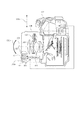
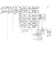
本発明に利用できる光学機器の例を示す。図1はカメラ本体107と交換レンズ106とで構成されるカメラシステムを示している。交換レンズ106に搭載される防振システムは光軸108に対して矢印101b、102bで示すシフトブレY及び角度ブレθに対してブレ補正を行う。
The example of the optical apparatus which can be utilized for this invention is shown. FIG. 1 shows a camera system including a
図1において、101は加速度検出手段(以下、加速度計)であり、矢印101aは加速度計101の検出方向である。102は角速度検出手段(以下、角速度計)であり、矢印102aは角速度計102の検出方向である。103はレンズCPUであり、像ブレを補正するのに必要な補正量を決定する補正量決定手段である。また、アクチュエータ104、コイル105は合わせて補正量決定手段から得られる補正量に基づいてブレ補正を行うブレ補正手段である。加速度計101と角速度計102の出力はレンズCPU103に入力後、演算され、コイル105のブレ補正目標値に変換される。レンズCPU103の出力はアクチュエータ104を介して、コイル105に入力され、ブレ補正レンズ109を駆動させてブレ補正を行う。
In FIG. 1,
ここで本実施例では、算出された補正量に基づいてブレ補正レンズを光軸に垂直な面内で移動させる、いわゆる光学防振を用いている。しかし補正量に基づいた補正の方法は光学防振に限らず、特開2008−048013号公報に示されるような方法でもよい。すなわち、撮像素子が出力する各撮影フレームの切り出し位置を変更することでブレの影響を軽減させる電子防振を用いたり、それらの組み合わせで補正を行ったりすることによっても本発明の目的は達成できる。 Here, in this embodiment, so-called optical image stabilization is used in which the blur correction lens is moved in a plane perpendicular to the optical axis based on the calculated correction amount. However, the correction method based on the correction amount is not limited to optical image stabilization, and may be a method as disclosed in Japanese Patent Laid-Open No. 2008-048013. That is, the object of the present invention can also be achieved by using electronic image stabilization that reduces the influence of blurring by changing the cut-out position of each shooting frame output by the image sensor, or by correcting with a combination thereof. .
図1では、カメラの鉛直方向(ピッチ方向)に生じるブレの構成を示したが、実際はカメラに水平でカメラの光軸に垂直な方向(ヨー方向)に生じるブレにも加速度計、角速度計がそれぞれ設けられており、ピッチ方向と同様の処理によりブレ補正が行われている。 In FIG. 1, the configuration of the shake that occurs in the vertical direction (pitch direction) of the camera is shown. Each is provided and shake correction is performed by the same processing as in the pitch direction.
また今回は、加速度計、角速度計をそれぞれ2つずつ用いた構成での説明を行ったが、検出軸が2軸あり、ピッチ、ヨー方向のブレを同時に検出できる計器を用いても良い。 In addition, this time, an explanation has been given of a configuration in which two accelerometers and two angular velocity meters are used, but an instrument that has two detection axes and can simultaneously detect pitch and yaw shakes may be used.
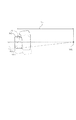
本実施例では、カメラに加わるシフトブレを、カメラから離れた場所に回転中心がある時の角度ブレとみなして求める。図2はカメラに加わるシフトブレY(101b)と角度ブレθ(102b)を示した図である。撮影光学系の主点位置におけるシフトブレY(101b)と角度ブレθ(102b)と、ブレの回転中心O(302p)を定めた場合の回転半径L(301)は下記の式で表すことができる。なお、回転半径L(301)は回転中心O(302p)から加速度計101までの水平距離である。
L=Y/tanθ・・・・(1)
L=V/tanω・・・・(2)
式(1)は加速度計101の出力を2階積分して算出したシフトブレY(101a)と、角速度計102の出力を1階積分した角度ブレθ(102b)から回転半径L(301)を求めた式である。式(2)は加速度計101の出力を1階積分して決定した速度Vと角速度計102の出力である角速度ωから回転半径L(301)を求めた式であり、式(1)、(2)のいずれの方法でも回転半径L(301)を求めることができる。
In this embodiment, the shift blur applied to the camera is determined as an angular blur when the center of rotation is located away from the camera. FIG. 2 is a diagram showing shift blur Y (101b) and angle blur θ (102b) applied to the camera. The shift blur Y (101b) and angle blur θ (102b) at the principal point position of the photographing optical system and the rotation radius L (301) when the rotation center O (302p) of the blur is determined can be expressed by the following equations. . The rotation radius L (301) is the horizontal distance from the rotation center O (302p) to the
L = Y / tan θ (1)
L = V / tan ω (2)
Equation (1) calculates the rotation radius L (301) from the shift blur Y (101a) calculated by second-order integration of the output of the
ここで、ブレの角度、角速度は小さいため、式(1)、(2)は下記の式で近似することができる。
L=Y/θ・・・・(3)
L=V/ω・・・・(4)
式(3)は加速度計101の出力を2階積分して求めた変位Yと、角速度計102の出力を1階積分して求めた角度θから求めた回転半径Lである。式(4)は加速度計101の出力を1階積分して求めた速度Vと、角速度計102の出力である角速度ωから回転半径Lを求めたものであるが、式(3)、式(4)のいずれの方法でも回転半径を求めることができる。
Here, since the blur angle and the angular velocity are small, the equations (1) and (2) can be approximated by the following equations.
L = Y / θ (3)
L = V / ω (4)
Equation (3) is a rotation radius L obtained from a displacement Y obtained by second-order integration of the output of the
ここで、撮影光学系の撮像面に生じるブレδについて説明する。撮影光学系の主点位置におけるシフトブレYと撮影光学系の角度ブレθ及び、撮影光学系の焦点距離f、撮影倍率βより撮像面に生じるブレδは下記の式(5)で求められる。
δ=(1+β)fθ+βY・・・・(5)
ここで、右辺第1項は角度ブレ量であり、右辺第2項はシフトブレ量である。右辺第1項の焦点距離f、撮影倍率βは撮影光学系のズーム及びフォーカス情報により得られ、角度θは角速度計の積分結果より求まるため、その情報に応じて図2のブロック図のように角度ブレ補正を行うことができる。右辺第2項では、加速度計の2階積分値であるシフトブレYとズーム及びフォーカス情報によって得られる撮影倍率βから、シフトブレ量を求めることができる。
Here, the blur δ occurring on the imaging surface of the imaging optical system will be described. Based on the shift blur Y at the principal point position of the photographing optical system, the angular blur θ of the photographing optical system, the focal length f of the photographing optical system, and the photographing magnification β, the blur δ generated on the imaging surface is obtained by the following equation (5).
δ = (1 + β) fθ + βY (5)
Here, the first term on the right side is the angle blur amount, and the second term on the right side is the shift blur amount. The focal length f and the imaging magnification β in the first term on the right side are obtained from zoom and focus information of the imaging optical system, and the angle θ is obtained from the integration result of the angular velocity meter, and accordingly, as shown in the block diagram of FIG. Angle blur correction can be performed. In the second term on the right side, the shift blur amount can be obtained from the shift blur Y which is the second order integral value of the accelerometer and the photographing magnification β obtained from the zoom and focus information.
しかし、本発明においては、式(5)を下記の式(6)のように書き直したブレδに対してブレ補正を行っている。
δ=(1+β)fθ+βLθ・・・・(6)
即ち、シフトブレに関しては加速度計出力を2階積分することで求められるシフトブレ変位Yを用いるのではなく、一度式(4)により、回転半径Lを求める。そして、回転半径Lと、角速ブレθとズーム及びフォーカス情報によって得られる撮影倍率βによりシフトブレ補正量を算出している。
However, in the present invention, the blur correction is performed on the blur δ that is rewritten from the formula (5) as the following formula (6).
δ = (1 + β) fθ + βLθ (6)
That is, regarding the shift blur, the rotation radius L is obtained once by the equation (4) instead of using the shift blur displacement Y obtained by second-order integration of the accelerometer output. Then, the shift blur correction amount is calculated from the rotation radius L, the angular velocity blur θ, and the shooting magnification β obtained from the zoom and focus information.
前述した通り、シフトブレは複数の周波数成分を含んでおり、個々に回転半径が異なる場合が多い。そこで本実施例ではシフトブレによる像ブレを補正する補正量の決定において、複数の周波数それぞれにおいて回転半径を取得する。以下に示す各実施例では、異なる3つの周波数においてそれぞれ回転半径を取得している。さらに得られた複数の回転半径を合成し、補正量を決定する。 As described above, shift blur includes a plurality of frequency components, and the radius of rotation is often different individually. Therefore, in this embodiment, in determining the correction amount for correcting the image blur due to the shift blur, the rotation radius is acquired at each of a plurality of frequencies. In each example described below, the rotation radii are acquired at three different frequencies. Further, a plurality of rotation radii obtained are combined to determine a correction amount.
また回転半径の合成を行う際、各回転半径の値の信頼性を評価し、その評価に応じて回転半径に重み付けをして合成を行うことを特徴とする。ここで重み付けとは複数の成分を合成する際、各成分に、ある指標に基づいた係数を掛けて演算を行う事を指す。また信頼性の評価は、角速度計及び加速度計の出力の少なくとも一方を基に行う。 Further, when combining the turning radii, the reliability of the values of the respective turning radii is evaluated, and the combining is performed by weighting the turning radii according to the evaluation. Here, the weighting means that, when a plurality of components are combined, calculation is performed by multiplying each component by a coefficient based on a certain index. The reliability is evaluated based on at least one of the outputs of the angular velocity meter and the accelerometer.
以下に実施例を示し、詳細に説明する。 Hereinafter, examples will be shown and described in detail.
本実施例では、角速度計102の出力である角速度と、加速度計101の出力から得られる速度との位相差を基に各回転半径の値の信頼性を評価する。その評価結果を反映して、各回転半径に重みを付けて合成し、その値を基に補正量が決定される。
In this embodiment, the reliability of the value of each turning radius is evaluated based on the phase difference between the angular velocity, which is the output of the
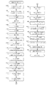
図3は上記のような補正量の決定とブレ補正を実現する防振システムのブロック図である。なお、このブロック図ではカメラのピッチ方向のブレを検出する構成を示しているが、ヨー方向も同様の構成であるため、ここではピッチ方向のみ説明を行う。 FIG. 3 is a block diagram of an anti-vibration system that realizes the correction amount determination and blur correction as described above. Although this block diagram shows a configuration for detecting blur in the pitch direction of the camera, the yaw direction has the same configuration, so only the pitch direction will be described here.
まず、先行技術にも開示がある角度ブレの補正について説明を行う。角速度計102の出力はレンズCPU103に取り込まれる。そしてその出力はハイパスフィルタ(以下、HPF)201に入力され、直流成分がカットされる。HPF201の出力は、積分フィルタ202により積分され、角度出力θに変換される。なお、これらHPFや積分フィルタ処理は、量子化された角速度計102の出力をレンズCPU103内で演算処理することで得られ、公知の差分方程式などで実現可能である。また、レンズCPU103に入力される前に、コンデンサや抵抗を利用してアナログ回路で実現することも可能である。
First, correction of angular blur, which is also disclosed in the prior art, will be described. The output of the
ここで、HPF201と積分フィルタ202のカットオフ周波数について説明する。一般的にブレの周波数域は1Hzから10Hzであるため、カットオフ周波数はブレの周波数域から離れた、0.1Hz以下の周波数成分をカットする1次のフィルタ特性にしている。積分フィルタ202の出力は敏感度調整手段203に入力される。敏感度調整手段203は不図示のフォーカスエンコーダやズームエンコーダからレンズCPU103に入力される、ズーム及びフォーカス情報204の出力に基づいて積分フィルタ202の出力を調整して、角度ブレ補正の目標値を決定する。敏感度調整手段203で調整を行う理由は、ズームやフォーカスなどレンズの光学状態の変化によって、コイル105のブレ補正ストロークに対する、カメラ像面でのブレ補正の敏感度が変化するためである。
Here, the cutoff frequencies of the
角度ブレ補正の目標値である敏感度調整手段203の出力は、ブレ補正の目標値としてレンズCPU103から出力される。レンズCPU103から出力されたブレ補正の目標値は、ドライバ104を介してコイル105に入力され、図1に示したブレ補正レンズ109を駆動させてブレ補正が行われる。
The output of the
なお、本発明では、角度ブレ補正の目標値である敏感度調整手段203の出力と、後述するシフトブレ補正の目標値である出力補正手段221の出力が、CPU103で加算されて、ドライバ104に出力される。
In the present invention, the output of the
次にシフトブレ補正のブロックについて説明する。角速度計102の出力はレンズCPU103に取り込まれる。そしてその出力は、HPF201に入力され、直流成分がカットされる。HPF201の出力は、位相調整フィルタ205により位相調整が行われる。ここで位相調整フィルタ205で位相調整を行うのは、後述する積分フィルタ210の出力との位相を合わせるためである。積分フィルタ210のカットオフ周波数は0.1Hzであるため、位相調整フィルタ205も0.1HzのHPFとなっている。位相調整フィルタ205の出力は、帯域抽出手段としてバンドパスフィルタ(以下、BPF)である角速度BPF206、207、208に入力され、それぞれのフィルタに設定された帯域の周波数成分が抽出され、出力される。本実施例では帯域抽出手段の役割を補正量決定手段であるレンズCPU109が兼ねているが、別途帯域抽出手段としてアナログのBPFなどを用いてもよい。
Next, the shift blur correction block will be described. The output of the
加速度計101の出力はHPF209に入力され、直流成分がカットされる。HPF209の出力は、積分フィルタ210に入力され、速度に変換される。このときのHPF209のカットオフ周波数は、HPF201と同じ0.1Hzであり、積分フィルタ210のカットオフ周波数は前述した通り、位相調整フィルタ205と同じ0.1Hzとなっている。積分フィルタ210はローパスフィルタ(以下、LPF)で構成されている。また位相調整フィルタ205は入力からLPF演算結果を減算することによってHPF演算を行っているため、積分フィルタ210と出力の位相は一致している。積分フィルタ210の出力は、速度BPF211、212、213に入力され、それぞれのフィルタに設定された周波数成分が出力される。
The output of the
ここで、第1の角速度BPF206、第1の速度BPF211はピークが2Hzの信号、第2の角速度BPF207、第2の速度BPF212はピークが5Hzの信号、第3の角速度BPF208、第3の速度BPF213はピークが10Hzの信号を出力する。
Here, the first angular velocity BPF 206 and the first velocity BPF 211 are signals with a peak of 2 Hz, the second angular velocity BPF 207 and the second velocity BPF 212 are signals with a peak of 5 Hz, a third
第1の角速度BPF206と第1の速度BPF211の出力は第1の回転半径演算手段214に入力される。同様に第2の角速度BPF207と第2の速度BPF212の出力は第2の回転半径演算手段215に入力される。さらに第3の角速度BPF208と第3の速度BPF213の出力は第3の回転半径演算手段216に入力されて、それぞれ式(4)に従い回転半径が算出される。
Outputs of the first angular velocity BPF 206 and the first velocity BPF 211 are input to the first turning radius calculation means 214. Similarly, the outputs of the second angular velocity BPF 207 and the second velocity BPF 212 are input to the second turning radius calculation means 215. Further, the outputs of the third
また、第1の角速度BPF206と第1の速度BPF211と第1の回転半径演算手段214の出力は、第1の位相差演算手段217に入力される。同様に第2の角速度BPF207と第2の速度BPF212と第2の回転半径演算手段215の出力は、第2の位相差演算手段218に入力される。さらに、第3の角速度BPF208と第3の速度BPF213と第3の回転半径演算手段219に入力されて、それぞれの速度と角速度の位相差が算出される。位相差の演算方法については後述する。
The first angular velocity BPF 206, the first velocity BPF 211, and the outputs of the first turning radius calculating means 214 are input to the first phase difference calculating means 217. Similarly, the second angular velocity BPF 207, the second velocity BPF 212, and the outputs of the second turning radius calculating means 215 are input to the second phase difference calculating means 218. Further, it is inputted to the third
次に、位相差演算手段217、218、219の出力に基づき、合成比補正手段220内で、回転半径演算手段214、215、216の出力の合成比を調整し、出力補正手段221に出力する。合成比補正手段220での演算方法が本実施例の特徴部分であり、後述する。
Next, based on the output of the phase difference calculation means 217, 218, 219, the composition ratio of the rotation radius calculation means 214, 215, 216 is adjusted in the composition ratio correction means 220 and output to the output correction means 221. . The calculation method in the composition
出力補正手段221では、積分フィルタ202の出力である角度θと合成比補正手段220の出力である回転半径Lから、式(3)に従いシフトブレ量Yを算出する。さらに、ズーム及びフォーカス情報204の出力に基づいてシフトブレ量Yを補正し、シフトブレ補正目標値を算出する。
The
出力補正手段221の出力であるシフトブレ補正目標値は、敏感度調整手段203の出力である角度ブレ補正目標値と加算され、ブレ補正目標値としてレンズCPU103より出力される。レンズCPU103の出力はドライバ104を介してコイル105に入力され、ブレ補正レンズ109を駆動させることによってブレ補正が行われる。
The shift blur correction target value output from the
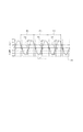
次に、回転半径の演算方法について説明する。図4(a)の波形は第1の回転半径演算手段214に入力された第1の角速度BPF206の出力波形であり、図4(b)の波形は第1の速度BPF211の出力波形である。矢印401、402、403はサンプリング周期であり、この周期間の第1の角速度BPF206と第1の速度BPF211の変位量を矢印404、405、406及び、407、408、409に示す。サンプリング周期401における角速度ωの変位量404及び、速度Vの変位量407と式(4)を用いて、回転半径Lを算出する。また、このとき第1の角速度BPF206と第1の速度BPF211の符号が逆の状態、つまり、シフトブレと角度ブレの向きが逆である場合、シフトブレは角度ブレを減少させる方向に働くため、回転半径Lはマイナスで算出する。また、サンプリング周期402、403においても同様の処理を行う。ここでサンプリング周期は、検出したいブレの周波数の中で最も高い10Hzにおいて、変曲点が2回入らないような周期、例えば25msec程度にするのが好ましい。
Next, a method for calculating the turning radius will be described. The waveform of FIG. 4A is an output waveform of the first angular velocity BPF 206 input to the first turning radius calculation means 214, and the waveform of FIG. 4B is an output waveform of the first velocity BPF 211.
この様にして角速度計、加速度計からの出力に基づいてサンプリング周期毎に算出した回転半径Lを、時系列でこれら複数の組を平均化したものを合成比補正手段220に出力する。ここで、回転半径Lを時系列で平均化したものを用いるのは、突発的な振幅の変化によって演算精度が低くなることを避けるためである。第2の回転半径演算手段215、第3の回転半径演算手段216でも同様の処理を行って回転半径を取得し、合成比補正手段220に出力している。 In this way, the rotation radius L calculated for each sampling period based on the outputs from the angular velocity meter and the accelerometer is output to the composite ratio correction means 220 by averaging these plural sets in time series. Here, the reason why the rotation radius L is averaged in time series is used in order to avoid a reduction in calculation accuracy due to a sudden change in amplitude. The second turning radius calculation means 215 and the third turning radius calculation means 216 perform the same processing to acquire the turning radius and output it to the composition ratio correction means 220.
次に、位相差の演算方法について説明する。図5(a)の波形は、第1の位相差演算手段217、第1の速度BPF211の出力波形である。図5(b)の波形は、第1の角速度BPF206に第1の回転半径演算手段214で求めた回転半径Lを乗じた波形507である。図5(c)の波形は、第1の速度BPF211と波形507の差分の波形508である。式(4)より回転半径Lに角速度ωを乗じた信号は速度Vであることから、波形507と第1の速度BPF211の波形は次元が揃っていることがわかる。 Next, a method for calculating the phase difference will be described. The waveform in FIG. 5A is an output waveform of the first phase difference calculation means 217 and the first speed BPF 211. The waveform shown in FIG. 5B is a waveform 507 obtained by multiplying the first angular velocity BPF 206 by the rotation radius L obtained by the first rotation radius calculation means 214. The waveform in FIG. 5C is a difference waveform 508 between the first speed BPF 211 and the waveform 507. From Expression (4), the signal obtained by multiplying the rotation radius L by the angular velocity ω is the velocity V, so that it can be seen that the waveforms of the waveform 507 and the first velocity BPF 211 have the same dimensions.
また、回転半径Lは図4を用いて説明した方法で求めているため、波形507はその逆算値となり、第1の速度BPF211の波形と振幅がほぼ等しくなるはずである。しかし、第1の速度BPF211と波形507は、その位相がずれている可能性がある。第1の位相差演算手段217では第1の速度BPF211と、波形508を一定周期でサンプリングし、その周期間での変位量の比から、角速度ωと速度Vの位相のずれ量を算出している。矢印501、502、503はサンプリング周期であり、この周期間の第1の速度BPF211と波形508の変位量を矢印504、505、506及び、509、510、511に示す。このとき、サンプリング周期は回転半径演算のサンプリング周期と同一であることが望ましい。
Further, since the rotation radius L is obtained by the method described with reference to FIG. 4, the waveform 507 is an inverse calculation value, and the amplitude of the waveform of the first velocity BPF 211 should be almost equal. However, the first speed BPF 211 and the waveform 507 may be out of phase. The first phase difference calculation means 217 samples the first velocity BPF 211 and the waveform 508 at a constant cycle, and calculates the amount of phase shift between the angular velocity ω and the velocity V from the ratio of the displacement amount between the cycles. Yes.
この様にして求めた位相のずれ量を所定の回数で平均化して、合成比補正手段220に出力する。ここで平均化するのは前述した回転半径の演算と同様、突発的な振幅や位相の変化によって演算精度が低くなることを避けるためである。第2の位相差演算手段218及び、第3の位相差演算手段219でも同様の処理を行って位相差を算出し、合成比補正手段220に出力している。 The phase shift amount thus obtained is averaged a predetermined number of times and output to the synthesis ratio correction means 220. The averaging is performed in order to avoid a decrease in calculation accuracy due to a sudden change in amplitude or phase, similar to the calculation of the turning radius described above. The second phase difference calculation means 218 and the third phase difference calculation means 219 perform the same processing to calculate the phase difference and output it to the synthesis ratio correction means 220.
次に、合成比補正手段220で行う処理を示す。合成比補正手段220では、各位相差演算手段の出力である角速度ωと速度Vの位相のずれ量が小さな周波数ほど、その周波数で取得された回転半径の合成比を大きくしている。ここで、ずれ量が小さいほど合成比を大きくしている理由について図5を用いて説明する。ブレの回転中心位置が一箇所で固定されている場合、第1の速度BPF211と波形507は一致する。しかし、回転中心が複数あり、それらの回転中心からの合成ブレを加速度計が検出している場合、各回転中心のブレの大きさによって速度信号と角速度信号の位相がずれてしまうためである。つまり、位相のずれが小さな周波数ほど、取得された回転半径の信頼性が高い。そのため、合成比補正手段220では、位相のずれが小さな周波数の回転半径ほど合成比を大きくすることによって、出力補正手段221で決定するシフトブレの補正量の補正精度を向上させている。また、本実施例では回転半径の演算の前に速度Vと角速度ωにBPFをかけているため、加速度計の出力の低周波成分に影響を及ぼすドリフトの影響が低減されている。
Next, processing performed by the synthesis
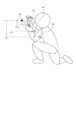
次に、合成比補正手段220で行う回転半径の合成比の調整方法について図6を用いて説明する。図6は人がカメラを構えた際のブレのイメージ図である。601、602、603はそれぞれ2Hz、5Hz、10Hzのブレの回転中心位置であり、604、605、606はレンズの主点位置に取り付けられた加速度計101からそれぞれの回転中心位置601、602、603までのピッチ方向における回転半径である。
Next, a method for adjusting the composition ratio of the rotation radii performed by the composition
ここで、2Hz、5Hz、10Hzの回転半径601をL1、L2、L3、角速度と速度の位相のずれをθ1、θ2、θ3としたとき、合成比補正手段220では下記の式を用いて補正用の回転半径を算出している。
Here, when the rotation radii 601 of 2 Hz, 5 Hz, and 10 Hz are L1, L2, and L3, and the phase shift between the angular velocity and the velocity is θ1, θ2, and θ3, the composition
![]()
![]()
式(7)では位相差の値が小さいものに対応する周波数の回転半径ほど、より大きい係数が振られ、重みがつけられている。 In equation (7), a larger coefficient is assigned and weighted as the rotational radius of the frequency corresponding to the smaller phase difference value.
次に、本実施例で行われるブレ補正処理について、図11のフローチャートを用いて説明する。ブレ補正処理は一定周期毎に発生するタイマー割り込み処理により行われる。本実施例ではステップ400が角速度検出ステップ、ステップ401加速度検出ステップ、ステップ406が速度取得ステップ、ステップ407〜412が帯域抽出ステップを担っている。また、ステップ413〜415が回転半径取得ステップ、ステップ416〜419が重み付けステップ、ステップ420が決定ステップである。
Next, the blur correction process performed in the present embodiment will be described with reference to the flowchart of FIG. The blur correction process is performed by a timer interrupt process that occurs at regular intervals. In this embodiment, step 400 is an angular velocity detection step, step 401 is an acceleration detection step, step 406 is a velocity acquisition step, and steps 407 to 412 are band extraction steps. Further, steps 413 to 415 are rotation radius acquisition steps,
(ステップ400)角速度計102pの信号をA/D変換する。A/D変換結果は、VAD_DATで設定される不図示のRAM領域に格納する。 (Step 400) The signal of the angular velocity meter 102p is A / D converted. The A / D conversion result is stored in a RAM area (not shown) set by VAD_DAT.
(ステップ401)加速度計101pの信号をA/D変換する。A/D変換結果は、ACCAD_DATで設定される不図示のRAM領域に格納する。 (Step 401) The signal of the accelerometer 101p is A / D converted. The A / D conversion result is stored in a RAM area (not shown) set by ACCAD_DAT.
(ステップ402)角速度計102pの信号VAD_DATを入力として、HPF401で演算を行う。 (Step 402) The signal VAD_DAT of the angular velocity meter 102p is inputted, and the HPF 401 performs calculation.
(ステップ403)ステップ402の演算結果を入力として、積分フィルタ202で積分演算を行う。その結果をDEG_DATで設定される不図示のRAM領域に格納する。DEG_DATはブレ角変位信号である。
(Step 403) Using the calculation result of step 402 as an input, the
(ステップ404)ステップ402の演算結果を入力として、位相調整フィルタ205で位相調整の演算を行う。この処理は、この後行われる加速度計101pの信号処理(HPF及び積分)と位相を合わせるために行われる。
(Step 404) Using the calculation result of step 402 as an input, the
(ステップ405)ACCAD_DATを入力として、HPF209で演算を行う。
(Step 405) With ACCAD_DAT as an input, the
(ステップ406)ステップ405の演算結果を入力として、積分フィルタ210で積分演算を行う。この演算結果はシフトブレの速度Vを表す信号ということになる。
(Step 406) The
(ステップ407)ステップ404の演算結果を入力として、透過率のピークを2Hzとする第1の角速度BPF206で演算を行う。この結果をW_BPF2HZ_DATで設定される不図示のRAM領域に格納する。 (Step 407) Using the calculation result of step 404 as an input, the calculation is performed with the first angular velocity BPF 206 having a transmittance peak of 2 Hz. The result is stored in a RAM area (not shown) set by W_BPF2HZ_DAT.
(ステップ408)ステップ404の演算結果を入力として、透過率のピークを5Hzとする第2の角速度BPF207で演算を行う。この結果をW_BPF5HZ_DATで設定される不図示のRAM領域に格納する。 (Step 408) Using the calculation result of step 404 as an input, the calculation is performed with the second angular velocity BPF 207 in which the transmittance peak is 5 Hz. This result is stored in a RAM area (not shown) set by W_BPF5HZ_DAT.
(ステップ409)ステップ404の演算結果を入力として、透過率のピークを10Hzとする第3の角速度BPF208で演算を行う。この結果をW_BPF10HZ_DATで設定される不図示のRAM領域に格納する。
(Step 409) Using the calculation result of step 404 as an input, the calculation is performed at the third
(ステップ410)ステップ406の演算結果を入力として、透過率のピークを2Hzとする第1の速度BPF211で演算を行う。この結果をV_BPF2HZ_DATで設定される不図示のRAM領域に格納する。 (Step 410) Using the calculation result of step 406 as an input, the calculation is performed at the first speed BPF 211 with a transmittance peak of 2 Hz. This result is stored in a RAM area (not shown) set by V_BPF2HZ_DAT.
(ステップ411)ステップ406の積分演算結果を入力として、透過率のピークを5Hzとする第2の速度BPF212で演算を行う。この結果をV_BPF5HZ_DATで設定される不図示のRAM領域に格納する。 (Step 411) Using the integration calculation result of Step 406 as an input, the calculation is performed at the second speed BPF 212 in which the transmittance peak is 5 Hz. This result is stored in a RAM area (not shown) set by V_BPF5HZ_DAT.
(ステップ412)ステップ406の積分演算結果を入力として、透過率のピークを10Hzとする速度BPF3213で演算を行う。この結果をV_BPF10HZ_DATで設定される不図示のRAM領域に格納する。 (Step 412) Using the integration calculation result of step 406 as an input, calculation is performed at a speed BPF 3213 where the transmittance peak is 10 Hz. This result is stored in a RAM area (not shown) set by V_BPF10HZ_DAT.
(ステップ413)W_BPF2HZ_DATとV_BPF2HZ_DATを比較し、回転半径L_2Hzを取得する。 (Step 413) W_BPF2HZ_DAT and V_BPF2HZ_DAT are compared, and a rotation radius L_2Hz is obtained.
(ステップ414)W_BPF5HZ_DATとV_BPF5HZ_DATを比較し、回転半径L_5Hzを取得する。 (Step 414) W_BPF5HZ_DAT and V_BPF5HZ_DAT are compared, and a rotation radius L_5 Hz is obtained.
(ステップ415)W_BPF10HZ_DATとV_BPF10HZ_DATを比較し、回転半径L_10Hzを取得する。 (Step 415) W_BPF10HZ_DAT and V_BPF10HZ_DAT are compared to obtain a turning radius L_10Hz.
(ステップ416)W_BPF2HZ_DATとV_BPF2HZ_DATと2Hzの回転半径L1の積を比較し、フィルタ透過帯域(2Hz)に対応したブレ信号の位相差θ1を算出する。 (Step 416) The product of W_BPF2HZ_DAT, V_BPF2HZ_DAT, and the rotation radius L1 of 2 Hz is compared, and the phase difference θ1 of the blur signal corresponding to the filter transmission band (2 Hz) is calculated.
(ステップ417)W_BPF5HZ_DATとV_BPF5HZ_DATと5Hzの回転半径L2の積を比較し、フィルタ透過帯域(5Hz)に対応したブレ信号の位相差θ2を算出する。 (Step 417) The product of W_BPF5HZ_DAT, V_BPF5HZ_DAT, and the rotation radius L2 of 5 Hz is compared, and the phase difference θ2 of the blur signal corresponding to the filter transmission band (5 Hz) is calculated.
(ステップ418)W_BPF10HZ_DATとV_BPF10HZ_DATと10Hzの回転半径L3の積を比較し、フィルタ透過帯域(10Hz)に対応したブレ信号の位相差θ3を算出する。 (Step 418) The product of W_BPF10HZ_DAT, V_BPF10HZ_DAT, and the rotation radius L3 of 10 Hz is compared, and the phase difference θ3 of the blur signal corresponding to the filter transmission band (10 Hz) is calculated.
(ステップ419)位相差が小さい周波数ほど大きい重み付けを行った回転半径Lを取得する(式(7))。 (Step 419) The turning radius L, which is weighted as the frequency with a smaller phase difference, is obtained (formula (7)).
(ステップ420)ズーム・フォーカス204のポジションから算出される撮影倍率β、焦点距離f、ステップ403で算出されたブレ角変位DEG_DAT、光学防振敏感度補正値αから、以下のような演算を行い、補正量を決定する。その演算結果は、SFTDRVで設定される不図示のRAM領域に格納する。
α{(1+β)×f×DEG_DAT+β×L×DEG_DAT}
(Step 420) The following calculation is performed from the photographing magnification β calculated from the position of the zoom / focus 204, the focal length f, the blur angular displacement DEG_DAT calculated in
α {(1 + β) × f × DEG_DAT + β × L × DEG_DAT}
(ステップ421)ブレ補正レンズの変位信号をA/D変換し、A/D結果をSFTPST で設定される不図示のRAM領域に格納する。 (Step 421) The displacement signal of the blur correction lens is A / D converted, and the A / D result is stored in a RAM area (not shown) set by SFTPST.
(ステップ422)フィードバック演算(SFTDRV−SFTPST)を行う。演算結果はSFT_DTで設定される不図示のRAM領域に格納する。 (Step 422) A feedback calculation (SFTDRV-SFTPST) is performed. The calculation result is stored in a RAM area (not shown) set by SFT_DT.
(ステップ423)ループゲインLPG_DTとSFT_DTを乗算する。演算結果はSFT_PWMで設定される不図示のRAM領域に格納する。 (Step 423) The loop gain LPG_DT is multiplied by SFT_DT. The calculation result is stored in a RAM area (not shown) set by SFT_PWM.
(ステップ424)安定な制御系にするために位相補償演算を行う。 (Step 424) Phase compensation calculation is performed in order to obtain a stable control system.
(ステップ425)ステップ423の演算結果をブレ補正駆動信号としてドライバ104に出力しブレ補正を行う。
(Step 425) The calculation result of step 423 is output to the
以上のように、本実施例ではステップ419において、角速度と速度の位相差が小さい周波数の回転半径ほど大きい重み付けを行った回転半径Lを取得する。そして、取得された回転半径Lに基づいて補正量を決定するので、より適正なシフトブレ補正を行うことが可能となる。重み付けの演算式としては、特に式(7)に限られたものではなく、位相差の値が小さいほど、それに対応する周波数域の回転半径に大きい重みが付くような演算式であればよい。 As described above, in the present embodiment, in step 419, the rotation radius L is obtained by weighting the rotation radius having the smaller frequency difference between the angular velocity and the velocity. Since the correction amount is determined based on the acquired rotation radius L, more appropriate shift blur correction can be performed. The calculation formula for weighting is not particularly limited to the formula (7), and any calculation formula may be used as long as the value of the phase difference is small, the rotation radius in the corresponding frequency range is given a large weight.
本実施例では異なる3つの周波数における回転半径を求め合成を行っているが、少なくとも2つの周波数における回転半径を求めていれば、本実施例を適用できるのは言うまでもない。 In this embodiment, turning radii at three different frequencies are obtained and synthesized, but it goes without saying that this embodiment can be applied if turning radii at at least two frequencies are obtained.
また本実施例では角速度と速度の位相差を評価手段とすることによって、他の実施例とは違い、回転中心がどの程度のばらつきを有しているかという観点で、各回転半径の信頼性を評価することが出来る。 In addition, in this embodiment, by using the phase difference between the angular velocity and the velocity as an evaluation means, unlike the other embodiments, the reliability of each rotation radius is improved in terms of how much the rotation center has a variation. Can be evaluated.
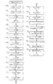
次に、本発明の実施例2について説明する。なお、簡略化のため実施例1と同一な構成については同一の符号を付して説明を省略し、本実施例に特徴的な部分のみを説明する。 Next, a second embodiment of the present invention will be described. For the sake of simplification, the same components as those in the first embodiment are denoted by the same reference numerals and description thereof is omitted, and only the characteristic features of the present embodiment will be described.
本実施例におけるカメラのメカ構成、ハード構成は実施例1と同じである。図8は本発明である実施例2におけるブロック図である。図2と図8のブロック図の違いは以下の通りである。 The mechanical configuration and hardware configuration of the camera in this embodiment are the same as those in the first embodiment. FIG. 8 is a block diagram according to the second embodiment of the present invention. Differences between the block diagrams of FIGS. 2 and 8 are as follows.
・位相差演算手段217、218、219の代わりに、角速度計102の振幅を算出する振幅演算手段701、702、703が設けられている。すなわち、実施例2では少なくとも2つの周波数(第1の周波数、第2の周波数)において、第1の振幅演算手段、第2の振幅演算手段の出力を基に、回転半径の合成が行われ、補正量が決定される。
-Instead of the phase difference calculation means 217, 218, 219, amplitude calculation means 701, 702, 703 for calculating the amplitude of the
・実施例1における合成比補正手段220の処理は、角速度と速度の位相差が小さな回転半径ほど大きな合成比にしていたが、本実施例では、角速度の振幅が大きな回転半径ほど大きな合成比にしている。
In the first embodiment, the composition
まず、角速度の振幅を用いて回転半径の合成比を調整する理由について説明する。回転半径の演算は式(4)を用いて行っている。式(4)より、回転半径と角速度は反比例しており、角速度がゼロ近傍にある場合、回転半径の値は著しく大きくなってしまう。通常のブレの回転中心が、たかだか撮影者の体近傍にあるであろうことを考慮すると、このとき算出される値は信頼性が低いと考えられる。 First, the reason why the rotation radius composition ratio is adjusted using the angular velocity amplitude will be described. The calculation of the turning radius is performed using Equation (4). From equation (4), the turning radius and the angular velocity are inversely proportional, and when the angular velocity is near zero, the value of the turning radius becomes remarkably large. Considering that the normal rotation center of blurring will be at most near the photographer's body, the value calculated at this time is considered to be unreliable.
以上のことから本実施例では、角速度の振幅が大きな周波数の回転半径ほど大きい重み付けになっている。 From the above, in the present embodiment, the weighting is greater as the rotational radius of the frequency with the larger angular velocity amplitude.
次に、振幅の演算方法について図8を用いて説明する。図9は第1の振幅演算手段(701)に入力された第1の角速度BPF206の出力波形である。矢印801、802、803はサンプリング周期であり、この周期間の第1の角速度BPF206の変位量を矢印804、805、806に示す。
Next, an amplitude calculation method will be described with reference to FIG. FIG. 9 shows an output waveform of the first angular velocity BPF 206 inputted to the first amplitude calculating means (701).
このようにしてサンプリング周期毎に求めた角速度の振幅を、所定の回数で平均化して合成比補正手段220に出力している。このとき、サンプリング周期は、回転半径演算手段におけるサンプリング周期と同一であることが好ましい。第2の振幅演算手段(702)、3(703)についても同様の処理を行い、合成比補正手段220に振幅を出力している。 The angular velocity amplitude thus obtained for each sampling period is averaged a predetermined number of times and output to the synthesis ratio correction means 220. At this time, it is preferable that the sampling period is the same as the sampling period in the turning radius calculating means. The same processing is performed for the second amplitude calculation means (702) and 3 (703), and the amplitude is output to the synthesis ratio correction means 220.
次に本実施例における合成比補正手段220で行う回転半径の合成比の調整方法について図6を用いて説明する。2Hzの回転半径601をL1、角速度の振幅をδ1、5Hzの回転半径602をL2、角速度の振幅をδ2、10Hzの回転半径をL3、角速度の振幅をδ3とする。このとき、合成比補正手段220では下記の式を用いて補正用の回転半径を算出している。
Next, a method for adjusting the composition ratio of the rotation radii performed by the composition
![]()
![]()
図10に実施例3におけるブレ補正動作のフローチャートを示す。主要な部分の動作をステップ501〜504に示し、そのほかの部分の動作は実施例1と同様のため、同じステップ番号を付して説明は省略する。
(ステップ501)W_BPF2HZ_DATの振幅δ1を算出する。
(ステップ502)W_BPF5HZ_DATの振幅δ2を算出する。
(ステップ503)W_BPF10HZ_DATの振幅δ3を算出する。
(ステップ504)角速度の振幅が大きな周波数のほど高い重み付けを行った回転半径を算出する(式(8))。
FIG. 10 shows a flowchart of the blur correction operation in the third embodiment. The operation of the main part is shown in steps 501 to 504, and the operation of the other parts is the same as that of the first embodiment.
(Step 501) The amplitude δ1 of W_BPF2HZ_DAT is calculated.
(Step 502) The amplitude δ2 of W_BPF5HZ_DAT is calculated.
(Step 503) The amplitude δ3 of W_BPF10HZ_DAT is calculated.
(Step 504) The turning radius with higher weighting is calculated for a frequency with a larger angular velocity amplitude (equation (8)).
以上のように、本実施例では上記の式(8)を用いて、角速度の振幅の値が大きいほど、それに対応する周波数域の回転半径に大きい重みが付くように演算が行われる。しかし、重み付けの演算式としては、特に上記の式(8)に限られたものではなく、角速度の振幅の値が大きいほど、それに対応する周波数域の回転半径に大きい重みが付くような演算式であればよい。 As described above, in the present embodiment, the calculation is performed using the above equation (8) so that the greater the value of the angular velocity amplitude, the greater the weighting is given to the rotation radius of the corresponding frequency region. However, the calculation formula for weighting is not particularly limited to the above formula (8), and the calculation formula is such that the greater the value of the angular velocity amplitude, the greater the weight of the corresponding rotation radius in the frequency region. If it is.
また本実施例では角速度の振幅の値を見て重み付けを行っているが、本実施例の目的は不自然に大きい値で算出された回転半径の重み付けを小さくすることであり、回転半径の値そのものを見て重み付けを行ってもよい。すなわち各周波数における回転半径の値を用いて、回転半径が大きい方に回転半径が小さい方に比べて小さい重み付けを行ってもよい。 In this embodiment, weighting is performed by looking at the value of the amplitude of the angular velocity. However, the purpose of this embodiment is to reduce the weight of the turning radius calculated with an unnaturally large value. You may weight by looking at itself. That is, using the value of the rotation radius at each frequency, a smaller weight may be applied to the larger rotation radius than to the smaller rotation radius.
また本実施例では異なる3つの周波数における回転半径を求め、重み付けを行っているが、少なくとも2つの周波数における回転半径を求め、それぞれの信頼性を評価し重み付けを行えば、本実施例の効果が得られるのは言うまでもない。 In this embodiment, the radii of rotation at three different frequencies are obtained and weighted. However, if the radii of rotation at at least two frequencies are obtained, and the reliability is evaluated and weighted, the effects of the present embodiment can be obtained. Needless to say, you can get it.
また本実施例では角速度の振幅によって各回転半径に重み付けをすることによって、各周波数のいずれかにおいて回転半径が著しく大きな値となっても、精度の高いブレ補正を行うことが可能となる。 Further, in this embodiment, by weighting each rotation radius with the amplitude of the angular velocity, it is possible to perform highly accurate blur correction even if the rotation radius becomes a significantly large value at any of the frequencies.
次に、本発明の実施例3について説明する。なお、簡略化のため実施例1、2と同一な構成については同一の符号を付して説明を省略し、実施例3に特徴的な部分のみを説明する。
Next,
本実施例におけるカメラのメカ構成、ハード構成は実施例1と同じである。図11は本発明である実施例2におけるブロック図であり、図7との違いは以下の通りである。 The mechanical configuration and hardware configuration of the camera in this embodiment are the same as those in the first embodiment. FIG. 11 is a block diagram according to the second embodiment of the present invention. The difference from FIG. 7 is as follows.
・振幅演算手段701、702、703に入力される信号が、BPF後の角速度信号から、BPF後の速度信号に変わっている。 The signal input to the amplitude calculation means 701, 702, 703 is changed from the angular velocity signal after BPF to the velocity signal after BPF.
・実施例2での合成比補正手段220の処理は、角速度の振幅が大きな回転半径ほど大きな合成比にしていたが、本実施例では速度の振幅が大きな回転半径ほど大きな重み付けにしている。
In the second embodiment, the composition
まず、速度の振幅を基準にして合成比を調整する理由について説明する。回転半径の演算は式(4)を用いて行っている。式(4)より、回転半径と速度は比例しており、速度が大きいほどシフトブレ量が大きくなることがわかる。 First, the reason for adjusting the synthesis ratio based on the velocity amplitude will be described. The calculation of the turning radius is performed using Equation (4). From equation (4), it can be seen that the radius of rotation is proportional to the speed, and that the amount of shift blur increases as the speed increases.
以上のことから本実施例では、速度が大きな周波数の回転半径ほど高い重み付けにしている。 From the above, in this embodiment, the higher the speed, the higher the weight of the rotation radius.
振幅演算手段701、702、703で行う振幅の演算方法は、前述した角速度の振幅の演算方法と基本的に同じであり、異なる点は入力が角速度から速度に変わっている点である。 The amplitude calculation method performed by the amplitude calculation means 701, 702, and 703 is basically the same as the above-described angular velocity amplitude calculation method, and the difference is that the input is changed from the angular velocity to the velocity.
また、合成比補正手段220で行う回転半径の重み付けの演算方法についても同様で、異なる点は角速度の振幅ではなく、速度の振幅を用いる点である。
The same applies to the calculation method of the weighting of the radius of rotation performed by the composition
2Hzの回転半径601をL1、速度の振幅をγ1、5Hzの回転半径602をL2、速度の振幅をγ2、10Hzの回転半径をL3、速度の振幅をγ3とする。このとき、合成比補正手段220では下記の式を用いて補正用の回転半径を算出する。
The
![]()
![]()
図12に実施例3におけるブレ補正動作のフローチャートを示す。主要な部分の動作ステップを601〜603に示し、そのほかの動作は実施例1と同様のため、同じステップ番号を付して説明は省略する。
(ステップ601)V_BPF2HZ_DATの振幅δ1を算出する。
(ステップ602)V_BPF5HZ_DATの振幅δ2を算出する。
(ステップ603)V_BPF10HZ_DATの振幅δ3を算出する。
FIG. 12 shows a flowchart of the blur correction operation in the third embodiment. The operation steps of the main part are indicated by
(Step 601) The amplitude δ1 of V_BPF2HZ_DAT is calculated.
(Step 602) The amplitude δ2 of V_BPF5HZ_DAT is calculated.
(Step 603) The amplitude δ3 of V_BPF10HZ_DAT is calculated.
以上のように、本実施例では、速度の振幅の値が大きいほど、それに対応する周波数域の回転半径に大きい重みが付くように演算が行われる。しかし、重み付けの演算式としては、特に上記の式(9)に限られたものではなく、速度の振幅の値が大きいほど、それに対応する回転半径に大きい重みが付くような演算式であればよい。 As described above, in this embodiment, the calculation is performed so that the greater the velocity amplitude value, the greater the weight of the corresponding rotation radius in the frequency region. However, the calculation formula for weighting is not particularly limited to the above formula (9), and any calculation formula can be used as long as the value of the velocity amplitude is increased, the corresponding rotation radius is given a greater weight. Good.
本実施例では異なる3つの周波数における回転半径を求め合成を行っているが、少なくとも2つの周波数における回転半径を求めていれば、本発明を適用できるのは言うまでもない。 In this embodiment, the radii of rotation at three different frequencies are obtained and synthesized, but it goes without saying that the present invention can be applied if the radii of rotation at at least two frequencies are obtained.
また本実施例では速度の振幅によって各回転半径に重み付けをすることによって、実質的なシフトブレの量を考慮した重み付けができる。これはもともと加速度計の出力がブレの成分のうちシフトブレのみを検出していることに起因する。すなわち、速度の振幅が小さいものはそもそもシフトブレの影響が小さいと判断できるからである。 Further, in this embodiment, weighting can be performed in consideration of a substantial shift blur amount by weighting each rotation radius according to the velocity amplitude. This is due to the fact that the output of the accelerometer detects only shift blur among the blur components. That is, it can be determined that the effect of shift blur is small in the first place when the velocity amplitude is small.
以上のように回転半径の値の信頼性を評価するものとして3つ実施例に挙げたが、評価する指標は上記に限られるものではなく、角速度計、加速度計の出力の少なくとも一方に基づいた値であればよい。特に本発明と同様に、角速度と速度(あるいは加速度)の位相差や、角速度の振幅、速度の振幅を実質的に見ていると考えられるものには当然本発明は適用できる。また、前述した3つの評価方法や他の評価方法と各実施例を組み合わせて用いると、さらに補正精度をあげることができる。 As described above, three examples are given to evaluate the reliability of the value of the radius of rotation, but the index to be evaluated is not limited to the above, and is based on at least one of the output of the angular velocity meter and the accelerometer. Any value is acceptable. In particular, as in the present invention, the present invention is naturally applicable to a case where it is considered that the phase difference between the angular velocity and the velocity (or acceleration), the angular velocity amplitude, and the velocity amplitude are substantially viewed. Further, when the above-described three evaluation methods and other evaluation methods are used in combination with each embodiment, the correction accuracy can be further increased.
また実施例ではデジタル1眼レフカメラに具備される交換レンズを例にして像ブレ補正機能を有する光学機器の説明をした。しかし本発明は小型で高性能なシステムにまとめることが可能なのでデジタルコンパクトカメラ、ビデオカメラや監視カメラ、ウェブカメラ、携帯電話のカメラ機能等にも展開できる。 In the embodiments, an optical device having an image blur correction function has been described by taking an interchangeable lens provided in a digital single lens reflex camera as an example. However, since the present invention can be integrated into a small and high-performance system, it can be expanded to a digital compact camera, a video camera, a surveillance camera, a web camera, a camera function of a mobile phone, and the like.
101 加速度計
102 角速度計
104 アクチュエータ
105 コイル
109 ブレ補正レンズ
214 回転半径演算手段
217 位相差演算手段
220 合成比補正手段
221 出力補正手段
DESCRIPTION OF
Claims (14)
前記光学機器の角速度を検出する角速度検出手段と、
前記光学機器の加速度を検出する加速度検出手段と、
前記像ブレを補正するために必要な補正量を決定する補正量決定手段と、
前記補正量に基づいて前記像ブレを補正するブレ補正手段と、
前記補正量決定手段は、異なる複数の周波数において前記光学機器に加わるブレの回転半径をそれぞれ取得し、前記角速度及び加速度の少なくとも一方の情報に基づいて前記複数の周波数における回転半径にそれぞれ重みを付け、その結果を基に前記補正量を決定することを特徴とする光学機器。 An optical instrument having an image blur correction function,
Angular velocity detection means for detecting the angular velocity of the optical instrument;
Acceleration detecting means for detecting the acceleration of the optical device;
Correction amount determining means for determining a correction amount necessary for correcting the image blur;
Blur correction means for correcting the image blur based on the correction amount;
The correction amount determination unit obtains the rotation radius of the blur applied to the optical apparatus at a plurality of different frequencies, and weights the rotation radius at the plurality of frequencies based on at least one of the angular velocity and acceleration information. An optical apparatus characterized in that the correction amount is determined based on the result.
前記光学機器の角速度を検出する角速度検出ステップと、
前記光学機器の加速度を検出する加速度検出ステップと、
異なる複数の周波数において前記光学機器に加わるブレの回転半径をそれぞれ取得する回転半径取得ステップと、
前記角速度及び加速度の少なくとも一方の情報に基づいて前記複数の周波数における回転半径にそれぞれ重みを付ける重み付けステップと、
前記重み付けステップにより得られた結果を基に像ブレを補正するために必要な補正量を決定する決定ステップと、を有することを特徴とする光学機器の制御方法。 A control method for controlling an optical apparatus having an image blur correction function,
An angular velocity detection step for detecting an angular velocity of the optical instrument;
An acceleration detecting step for detecting an acceleration of the optical device;
A rotation radius acquisition step of acquiring a rotation radius of a blur applied to the optical apparatus at a plurality of different frequencies, respectively;
A weighting step of weighting each of the turning radii at the plurality of frequencies based on at least one of the angular velocity and the acceleration;
A determining step for determining a correction amount necessary for correcting image blur based on the result obtained by the weighting step.
前記回転半径取得ステップは、前記複数の周波数における前記角速度と前記速度の比によって前記ブレの回転半径を取得することを特徴とする請求項8に記載の光学機器の制御方法。 A speed acquisition step of acquiring the speed of the optical device based on the acceleration information;
9. The method of controlling an optical instrument according to claim 8, wherein the turning radius obtaining step obtains the turning radius of the blur based on a ratio between the angular velocity and the velocity at the plurality of frequencies.
Priority Applications (4)
| Application Number | Priority Date | Filing Date | Title |
|---|---|---|---|
| JP2008222017A JP5111306B2 (en) | 2008-08-29 | 2008-08-29 | Optical apparatus having image blur correction function and control method thereof |
| CN200910167476.3A CN101661208B (en) | 2008-08-29 | 2009-08-25 | Apparatus having image shake correction function and method of controlling the same |
| US12/548,331 US8497915B2 (en) | 2008-08-29 | 2009-08-26 | Apparatus having image shake correction function and method of controlling the same and image shake correction apparatus used for optical apparatus |
| US13/928,733 US9007470B2 (en) | 2008-08-29 | 2013-06-27 | Apparatus having image shake correction function and method of controlling the same |
Applications Claiming Priority (1)
| Application Number | Priority Date | Filing Date | Title |
|---|---|---|---|
| JP2008222017A JP5111306B2 (en) | 2008-08-29 | 2008-08-29 | Optical apparatus having image blur correction function and control method thereof |
Publications (3)
| Publication Number | Publication Date |
|---|---|
| JP2010054986A true JP2010054986A (en) | 2010-03-11 |
| JP2010054986A5 JP2010054986A5 (en) | 2011-10-13 |
| JP5111306B2 JP5111306B2 (en) | 2013-01-09 |
Family
ID=41724792
Family Applications (1)
| Application Number | Title | Priority Date | Filing Date |
|---|---|---|---|
| JP2008222017A Active JP5111306B2 (en) | 2008-08-29 | 2008-08-29 | Optical apparatus having image blur correction function and control method thereof |
Country Status (3)
| Country | Link |
|---|---|
| US (2) | US8497915B2 (en) |
| JP (1) | JP5111306B2 (en) |
| CN (1) | CN101661208B (en) |
Cited By (7)
| Publication number | Priority date | Publication date | Assignee | Title |
|---|---|---|---|---|
| JP2012088466A (en) * | 2010-10-19 | 2012-05-10 | Canon Inc | Vibration-proof controller, imaging apparatus, and vibration-proof control method |
| JP2013130836A (en) * | 2011-12-22 | 2013-07-04 | Canon Inc | Vibration control device, vibration control method, optical instrument, and imaging apparatus |
| WO2013108434A1 (en) * | 2012-01-19 | 2013-07-25 | オリンパス株式会社 | Shaking amount detection device, imaging device, and shaking amount detection method |
| JP2013148717A (en) * | 2012-01-19 | 2013-08-01 | Olympus Corp | Shake amount detecting device, imaging apparatus, and shake amount detection method |
| JP2013246401A (en) * | 2012-05-29 | 2013-12-09 | Olympus Corp | Shake amount detection device, imaging apparatus, and shake amount detection method |
| JP2020148905A (en) * | 2019-03-13 | 2020-09-17 | キヤノン株式会社 | Imaging apparatus, method for controlling the same, program, and storage medium |
| US11381746B2 (en) | 2019-10-30 | 2022-07-05 | Canon Kabushiki Kaisha | Apparatus and method for setting a correction axis for image stabilization |
Families Citing this family (21)
| Publication number | Priority date | Publication date | Assignee | Title |
|---|---|---|---|---|
| JP5111306B2 (en) * | 2008-08-29 | 2013-01-09 | キヤノン株式会社 | Optical apparatus having image blur correction function and control method thereof |
| CN103477277B (en) * | 2011-04-12 | 2014-12-10 | 富士胶片株式会社 | Imaging device |
| EP2533518B1 (en) * | 2011-06-10 | 2014-09-10 | Canon Kabushiki Kaisha | Shake compensation apparatus, shake compensation control method, and image capturing apparatus and control method thereof |
| JP6098874B2 (en) * | 2012-09-04 | 2017-03-22 | パナソニックIpマネジメント株式会社 | Imaging apparatus and image processing apparatus |
| CN104685863B (en) * | 2012-09-27 | 2017-11-03 | 富士胶片株式会社 | Camera device and image processing method |
| GB2508471B (en) | 2012-11-29 | 2015-10-07 | Cooke Optics Ltd | Camera lens assembly |
| KR101932723B1 (en) * | 2012-12-28 | 2018-12-27 | 삼성전자주식회사 | Photographing apparatus |
| JP6074298B2 (en) * | 2013-03-18 | 2017-02-01 | キヤノン株式会社 | Imaging apparatus, image processing apparatus, and control method thereof |
| JP6045430B2 (en) * | 2013-04-18 | 2016-12-14 | オリンパス株式会社 | Imaging apparatus and image blur correction method thereof |
| CN103533238A (en) * | 2013-09-30 | 2014-01-22 | 武汉烽火众智数字技术有限责任公司 | Image stabilization device and method for dome camera |
| JP6677098B2 (en) * | 2015-07-01 | 2020-04-08 | 株式会社リコー | Spherical video shooting system and program |
| CN105100614B (en) * | 2015-07-24 | 2018-07-31 | 小米科技有限责任公司 | The implementation method and device of optical anti-vibration, electronic equipment |
| CN107079085B (en) * | 2015-11-05 | 2019-10-25 | 华为技术有限公司 | A kind of stabilization photographic method, device and camera installation |
| JP6880979B2 (en) * | 2016-11-30 | 2021-06-02 | 株式会社リコー | Vibration suppressor and electronic equipment |
| JP6843651B2 (en) * | 2017-03-01 | 2021-03-17 | キヤノン株式会社 | Image processing device, control method of image processing device, and program |
| JP2018146663A (en) * | 2017-03-02 | 2018-09-20 | キヤノン株式会社 | Image tremor correction device, control method of the same, imaging device, and lens device |
| CN106713770B (en) * | 2017-03-27 | 2020-03-24 | 联想(北京)有限公司 | Photographing processing method and electronic equipment |
| CN108732922A (en) * | 2018-04-28 | 2018-11-02 | 桂林飞宇科技股份有限公司 | A kind of stabilizer control system and control method |
| CN112313576B (en) * | 2018-06-19 | 2022-09-06 | 杭州他若定位科技有限公司 | Camera mobile device support with stabilizing function |
| JPWO2021014716A1 (en) * | 2019-07-24 | 2021-01-28 | ||
| US11223767B1 (en) | 2020-12-16 | 2022-01-11 | Semiconductor Components Industries, Llc | Methods and apparatus for optical image stabilization |
Citations (4)
| Publication number | Priority date | Publication date | Assignee | Title |
|---|---|---|---|---|
| JPH07294979A (en) * | 1994-04-28 | 1995-11-10 | Canon Inc | Camera-shake correcting device |
| JP2004295027A (en) * | 2003-03-28 | 2004-10-21 | Nikon Corp | Blurring correction device |
| JP2005114845A (en) * | 2003-10-03 | 2005-04-28 | Nikon Corp | Vibration detecting device and blurring correcting device |
| JP2007019571A (en) * | 2005-07-05 | 2007-01-25 | Canon Inc | Optical apparatus and control program thereof |
Family Cites Families (6)
| Publication number | Priority date | Publication date | Assignee | Title |
|---|---|---|---|---|
| US6233009B1 (en) * | 1993-09-08 | 2001-05-15 | Canon Kabushiki Kaisha | Image-shake correcting device for detecting vibration frequency and for changing vibration characteristics |
| JP3513950B2 (en) * | 1993-12-14 | 2004-03-31 | 株式会社ニコン | Image stabilization camera |
| JP4717651B2 (en) * | 2006-02-07 | 2011-07-06 | キヤノン株式会社 | Image shake correction apparatus and imaging apparatus |
| US7797313B1 (en) * | 2006-03-28 | 2010-09-14 | Symantec Operating Corporation | Relevance ranking in a computer system |
| JP4717748B2 (en) | 2006-08-11 | 2011-07-06 | キヤノン株式会社 | Camera body and camera system having the same |
| JP5111306B2 (en) * | 2008-08-29 | 2013-01-09 | キヤノン株式会社 | Optical apparatus having image blur correction function and control method thereof |
-
2008
- 2008-08-29 JP JP2008222017A patent/JP5111306B2/en active Active
-
2009
- 2009-08-25 CN CN200910167476.3A patent/CN101661208B/en active Active
- 2009-08-26 US US12/548,331 patent/US8497915B2/en not_active Expired - Fee Related
-
2013
- 2013-06-27 US US13/928,733 patent/US9007470B2/en active Active
Patent Citations (4)
| Publication number | Priority date | Publication date | Assignee | Title |
|---|---|---|---|---|
| JPH07294979A (en) * | 1994-04-28 | 1995-11-10 | Canon Inc | Camera-shake correcting device |
| JP2004295027A (en) * | 2003-03-28 | 2004-10-21 | Nikon Corp | Blurring correction device |
| JP2005114845A (en) * | 2003-10-03 | 2005-04-28 | Nikon Corp | Vibration detecting device and blurring correcting device |
| JP2007019571A (en) * | 2005-07-05 | 2007-01-25 | Canon Inc | Optical apparatus and control program thereof |
Cited By (10)
| Publication number | Priority date | Publication date | Assignee | Title |
|---|---|---|---|---|
| JP2012088466A (en) * | 2010-10-19 | 2012-05-10 | Canon Inc | Vibration-proof controller, imaging apparatus, and vibration-proof control method |
| JP2013130836A (en) * | 2011-12-22 | 2013-07-04 | Canon Inc | Vibration control device, vibration control method, optical instrument, and imaging apparatus |
| US9568742B2 (en) | 2011-12-22 | 2017-02-14 | Canon Kabushiki Kaisha | Image stabilization apparatus, control method thereof, optical apparatus and image capturing apparatus |
| WO2013108434A1 (en) * | 2012-01-19 | 2013-07-25 | オリンパス株式会社 | Shaking amount detection device, imaging device, and shaking amount detection method |
| JP2013148717A (en) * | 2012-01-19 | 2013-08-01 | Olympus Corp | Shake amount detecting device, imaging apparatus, and shake amount detection method |
| US9386225B2 (en) | 2012-01-19 | 2016-07-05 | Olympus Corporation | Shaking amount detecting apparatus, image pickup apparatus, and shaking amount detecting method |
| JP2013246401A (en) * | 2012-05-29 | 2013-12-09 | Olympus Corp | Shake amount detection device, imaging apparatus, and shake amount detection method |
| JP2020148905A (en) * | 2019-03-13 | 2020-09-17 | キヤノン株式会社 | Imaging apparatus, method for controlling the same, program, and storage medium |
| JP7233260B2 (en) | 2019-03-13 | 2023-03-06 | キヤノン株式会社 | Image blur correction control device and its control method, program, storage medium |
| US11381746B2 (en) | 2019-10-30 | 2022-07-05 | Canon Kabushiki Kaisha | Apparatus and method for setting a correction axis for image stabilization |
Also Published As
| Publication number | Publication date |
|---|---|
| US8497915B2 (en) | 2013-07-30 |
| US20130287381A1 (en) | 2013-10-31 |
| CN101661208A (en) | 2010-03-03 |
| US9007470B2 (en) | 2015-04-14 |
| US20100053344A1 (en) | 2010-03-04 |
| JP5111306B2 (en) | 2013-01-09 |
| CN101661208B (en) | 2011-05-11 |
Similar Documents
| Publication | Publication Date | Title |
|---|---|---|
| JP5111306B2 (en) | Optical apparatus having image blur correction function and control method thereof | |
| JP5121911B2 (en) | Anti-shake control device, imaging device, and anti-shake control method | |
| JP6614810B2 (en) | Blur correction device, imaging device, and blur correction method | |
| JP5956749B2 (en) | Anti-vibration control device, control method therefor, and imaging device | |
| JP6362556B2 (en) | Control device, imaging device, control method, program, and storage medium | |
| JP5181001B2 (en) | Image blur correction apparatus, control method therefor, and imaging apparatus and optical apparatus equipped with the image blur correction apparatus | |
| JP5094606B2 (en) | Image shake correction apparatus, optical apparatus including the same, image pickup apparatus, and image shake correction apparatus control method | |
| JP2015034879A (en) | Image shake correction device and control method for the same, lens barrel, optical device and imaging device | |
| JP2010025961A (en) | Image stabilization control apparatus and image capturing apparatus | |
| JP2017090580A (en) | Image blur correction device and method | |
| JP2013130836A (en) | Vibration control device, vibration control method, optical instrument, and imaging apparatus | |
| JP5268546B2 (en) | Optical apparatus and control method thereof | |
| JP2007158853A (en) | Shake correcting device | |
| JP5631063B2 (en) | Tilt detection device, shake correction device, imaging device, and tilt detection method thereof | |
| JP6659126B2 (en) | Image blur correction device, image blur correction method, imaging device, and program | |
| JP2005257919A (en) | Image blurring correction device | |
| JP2010096938A (en) | Optical apparatus having image-blur correcting function and control method therefor | |
| KR101608828B1 (en) | Apparatus for vibration compensation of gyro sensor of mobile camera | |
| JP5984467B2 (en) | Image blur correction device, optical apparatus, imaging device, and image blur correction device control method | |
| JP2014041230A (en) | Optical device having image blur correction function and control method of the same | |
| JP2014016515A (en) | Optical apparatus having image blur correction function and control method of the same | |
| JP2010054985A (en) | Optical equipment and control method therefor | |
| JP2010060798A (en) | Optical equipment and control method thereof | |
| JP6448709B2 (en) | Image shake correction apparatus, image shake correction method, imaging apparatus, and optical apparatus | |
| JP2012123261A (en) | Vibration isolation controlling device |
Legal Events
| Date | Code | Title | Description |
|---|---|---|---|
| RD04 | Notification of resignation of power of attorney |
Free format text: JAPANESE INTERMEDIATE CODE: A7424 Effective date: 20100201 |
|
| RD01 | Notification of change of attorney |
Free format text: JAPANESE INTERMEDIATE CODE: A7421 Effective date: 20100630 |
|
| A521 | Request for written amendment filed |
Free format text: JAPANESE INTERMEDIATE CODE: A523 Effective date: 20110826 |
|
| A621 | Written request for application examination |
Free format text: JAPANESE INTERMEDIATE CODE: A621 Effective date: 20110826 |
|
| A977 | Report on retrieval |
Free format text: JAPANESE INTERMEDIATE CODE: A971007 Effective date: 20120827 |
|
| TRDD | Decision of grant or rejection written | ||
| A01 | Written decision to grant a patent or to grant a registration (utility model) |
Free format text: JAPANESE INTERMEDIATE CODE: A01 Effective date: 20120911 |
|
| A01 | Written decision to grant a patent or to grant a registration (utility model) |
Free format text: JAPANESE INTERMEDIATE CODE: A01 |
|
| A61 | First payment of annual fees (during grant procedure) |
Free format text: JAPANESE INTERMEDIATE CODE: A61 Effective date: 20121009 |
|
| FPAY | Renewal fee payment (event date is renewal date of database) |
Free format text: PAYMENT UNTIL: 20151019 Year of fee payment: 3 |
|
| R151 | Written notification of patent or utility model registration |
Ref document number: 5111306 Country of ref document: JP Free format text: JAPANESE INTERMEDIATE CODE: R151 |
|
| FPAY | Renewal fee payment (event date is renewal date of database) |
Free format text: PAYMENT UNTIL: 20151019 Year of fee payment: 3 |