JP2010054919A - Relief-type diffraction grating or hologram - Google Patents
Relief-type diffraction grating or hologram Download PDFInfo
- Publication number
- JP2010054919A JP2010054919A JP2008221177A JP2008221177A JP2010054919A JP 2010054919 A JP2010054919 A JP 2010054919A JP 2008221177 A JP2008221177 A JP 2008221177A JP 2008221177 A JP2008221177 A JP 2008221177A JP 2010054919 A JP2010054919 A JP 2010054919A
- Authority
- JP
- Japan
- Prior art keywords
- diffraction grating
- hologram
- information
- relief
- relief type
- Prior art date
- Legal status (The legal status is an assumption and is not a legal conclusion. Google has not performed a legal analysis and makes no representation as to the accuracy of the status listed.)
- Granted
Links
Images

Abstract
Description
本発明は、主にセキュリティ用途に使用される凹凸構造に関し、詳しくは、回折格子やホログラムなど、セキュリティ用途で使用される各種絵柄の中に、目視では確認困難な情報として組み込まれた凹凸構造による隠し情報を有するレリーフ型回折格子又はホログラムに関する。 The present invention relates to a concavo-convex structure mainly used for security applications, and more particularly, to a concavo-convex structure incorporated as information that is difficult to confirm visually in various patterns used for security applications such as diffraction gratings and holograms. The present invention relates to a relief type diffraction grating or hologram having hidden information.
(主なる用途)本発明のレリーフ型回折格子又はホログラムの主なる用途としては、偽造防止分野に使用される回折格子又はホログラムであって、具体的には、クレジットカード等の偽造されて使用されると、カード保持者やカード会社等に損害を与え得るもの、運転免許証、社員証、会員証等の身分証明書、入学試験用の受験票、パスポート等、紙幣、商品券、ポイントカード、株券、証券、抽選券、馬券、預金通帳、乗車券、通行券、航空券、種々の催事の入場券、遊戯券、交通機関や公衆電話用のプリペイドカード等がある。 (Main use) The main use of the relief type diffraction grating or hologram of the present invention is a diffraction grating or hologram used in the field of anti-counterfeiting. Specifically, it is used after being counterfeited such as a credit card. This can cause damage to cardholders and card companies, driver's licenses, employee ID cards, ID cards such as membership cards, admission tickets for entrance examinations, passports, banknotes, gift certificates, point cards, There are stock certificates, securities, lottery tickets, horse tickets, passbooks, boarding tickets, passports, air tickets, admission tickets for various events, play tickets, prepaid cards for transportation and public telephones, and the like.
これらはいずれも、経済的、もしくは社会的な価値を有する情報を保持した情報記録体であり、偽造による損害を防止する目的で、記録体そのものの真正性を識別できる機能を有することが望まれる。 Each of these is an information recording body that holds information having economic or social value, and it is desirable to have a function that can identify the authenticity of the recording body for the purpose of preventing damage caused by forgery. .
また、これら情報記録体以外であっても、高額商品、例えば、高級腕時計、高級皮革製品、貴金属製品、もしくは宝飾品等の、しばしば、高級ブランド品と言われるもの、または、それら高額商品の収納箱やケース等も偽造され得るものである。また、量産品でも有名ブランドのもの、例えば、オーディオ製品、電化製品等、または、それらに吊り下げられるタグも、偽造の対象となりやすい。 In addition to these information recording media, expensive products such as luxury watches, luxury leather products, precious metal products, jewelry, etc., often referred to as luxury brand products, or storage of such expensive products. Boxes and cases can also be forged. In addition, mass-produced products of famous brands, such as audio products, electrical appliances, etc., or tags that are hung on them are also subject to forgery.
さらに、著作物である音楽ソフト、映像ソフト、コンピュータソフト、もしくはゲームソフト等が記録された記憶体、またはそれらのケース等も、やはり偽造の対象となり得る。また、プリンター用のトナー、用紙など、交換する備品を純正材料に限定している製品などにも、偽造による損害を防止する目的で、そのものの真正性を識別できる機能を有することが望まれる。 Furthermore, a storage body in which music software, video software, computer software, game software, or the like, which is a copyrighted work, or cases thereof can also be forged. In addition, it is desirable that products such as printer toner, paper, and the like in which supplies to be replaced are limited to genuine materials have a function of identifying their authenticity for the purpose of preventing damage caused by forgery.
特に、本発明のレリーフ型回折格子又はホログラムは、同一のものを作成することが物理的にも経済的にも不可能なものが望まれる分野、すなわち、芸術品や、骨董品等の鑑定しなければその価値を証明できない分野、もしくは、非常に貴重なものであって模造品でないことを所有者や関係者のみ知り得る方法により確認する必要がある分野等に最適である。 In particular, the relief-type diffraction grating or hologram of the present invention is used in the field where it is physically impossible and economical to produce the same thing, that is, for arts and antiques. Otherwise, it is most suitable for the field where the value cannot be proved, or the field where it is necessary to confirm by the method that only the owner or the related person can know that it is very precious and not imitation.
高額な金券類に着目すると、近年、カラーコピー機による偽造事件が頻発している。
そのために、高額紙幣や商品券等の金券類は、デザインの一部にカラーコピー機のセンサーでは読み取ることができない小さな網点や細線を、同じ反射濃度でデザインされた絵柄の中に組み込んでいる。その結果、これらの高額紙幣や商品券をカラーコピー機によって複写しようとすると、コピー機のスキャナーが小さな網点や細線を読み落とし、その部分が白く抜けることでコピー品であると判別している。
Focusing on expensive cash vouchers, forgery cases with color copiers have frequently occurred in recent years.
For this reason, money vouchers such as high-value banknotes and gift certificates incorporate a small halftone dot or fine line that cannot be read by a color copier sensor in a part of the design, in a pattern designed with the same reflection density. . As a result, when trying to copy these high-value banknotes and gift certificates with a color copier, the copier scanner reads out small dots and fine lines, and those parts are identified as white and are identified as copies. .
(背景技術)
また、高度な複製技術を必要とするホログラムが、一部の高額紙幣や、その他の金券類に採用されている。
ホログラムは、また、その凹凸面に金属の反射層を形成することにより、ホログラムをコピーした時にホログラム形成部を黒に再現するため、コピー牽制手段として利用されている。
しかしながら、技術の進歩によって、ホログラムに近似の偽造品が出現するようになってきた。そして、このような偽造品をチェックするために、ホログラムの光回折構造即ち回折格子の中に判別困難な隠し情報を組み込んで真偽判別の手段として使用する技術が開示されている。
ところがこれらの技術を使用した製品も、見る角度によって隠し情報が微かに判別されてしまうという課題があった。
(Background technology)
In addition, holograms that require advanced duplication techniques have been adopted for some high-value banknotes and other cash vouchers.
Holograms are also used as copy restraining means because a metal reflection layer is formed on the uneven surface to reproduce the hologram forming portion in black when the hologram is copied.
However, due to technological progress, counterfeit products similar to holograms have appeared. In order to check such a counterfeit product, a technique is disclosed in which hidden information that is difficult to discriminate is incorporated into a light diffraction structure of a hologram, that is, a diffraction grating, and used as a means for discriminating authenticity.
However, products using these technologies also have a problem that hidden information is slightly discriminated depending on the viewing angle.
このような課題に対して、目視手段による判別が極めて困難な隠し情報を含む回折格子により構成された真贋識別構造及びその作製方法が提供されている(例えば、特許文献1参照)。特許文献1で開示されている技術は、回折格子で構成されたデザインの中に、第一の隠し情報を有し、その第一の隠し情報の中にさらに文字・記号又はこれらの組み合わせによる第ニの隠し情報を凹凸によって形成するものである。この第ニの隠し情報のサイズは、0.5μm〜50μmであり、簡易な顕微鏡を用いても判読が困難である。 In order to solve such a problem, an authenticity identification structure constituted by a diffraction grating including hidden information that is extremely difficult to discriminate by a visual means and a manufacturing method thereof are provided (for example, see Patent Document 1). The technique disclosed in Patent Document 1 has first hidden information in a design constituted by a diffraction grating, and the first hidden information further includes characters / symbols or a combination thereof. The hidden information is formed by unevenness. The size of the second hidden information is 0.5 μm to 50 μm and is difficult to read even with a simple microscope.
また、例え第ニの隠し情報として形成されている凹凸の情報を精密な顕微鏡で判読したとしても、その情報は無秩序(ランダムな)情報であり、且つ、そのサイズも無秩序に形成されているため、偽造を試みる場合は、回折格子デザインの全ての部分の情報及びサイズを判読し尽くして再現しなければ真正なものを作ることは不可能であるため、高い偽造防止効果を有する。 Moreover, even if the information on the unevenness formed as the second hidden information is read with a precise microscope, the information is random (random) information and the size is also formed randomly. When trying to counterfeit, since it is impossible to make an authentic one unless the information and size of all parts of the diffraction grating design are completely read and reproduced, it has a high anti-counterfeiting effect.
特許文献1に開示されている技術は、その無秩序性によって偽造防止効果を高めたものであるが、「無秩序」であることと、凹凸の「周期性」により透過光若しくは反射光の干渉を発生させて光を「強く」回折させるという「回折の原理・原則」とは、相反し、この技術により作成された回折格子又はホログラム全体を目視にて観察した場合、その回折画像やホログラム画像の明るさや色合いに大きなバラツキ・ムラが発生していた。 The technique disclosed in Patent Document 1 has improved anti-counterfeiting effect due to its disorder, but it is “disorder” and generates interference of transmitted light or reflected light due to “periodicity” of unevenness. This is contrary to the “diffraction principle / principle” of diffracting light “strongly”. When the entire diffraction grating or hologram produced by this technique is observed visually, the brightness of the diffraction image or hologram image There were large variations and unevenness in the shade.
前記課題を解決するために、本発明のレリーフ型回折格子又はホログラムの第1の態様は、回折格子線群の断面形状が、凸部(ライン部:L部)と凹部(スペース部:S部)からなるレリーフ型回折格子又はホログラムにおいて、当該回折格子線群に、少なくとも1本の「特定回折格子線」が混在しているものであって、且つ、当該回折格子線群の凹凸比(L/S比)と、前記特定回折格子線の凹凸比(凸部:所定情報表示面積と、凹部:非表示部面積との比)が同一であることを特徴とするものである。 In order to solve the above-described problems, the first aspect of the relief type diffraction grating or hologram of the present invention is that the diffraction grating line group has a cross-sectional shape of a convex part (line part: L part) and a concave part (space part: S part). ) In which the diffraction grating line group includes at least one “specific diffraction grating line”, and the concave-convex ratio (L / S ratio) and the concavo-convex ratio of the specific diffraction grating line (ratio of convex portion: predetermined information display area and concave portion: non-display portion area) are the same.
「特定回折格子線」とは、所定の文字、記号、図柄の何れか、または、これらの組み合わせ情報(以下所定情報という)を表示する一列の凹凸構造で構成された回折格子線であり、この所定情報を「隠し情報」と位置づける。
回折格子線群は、基本構造として、回折格子線が平行に複数並んでおり、この複数の線群の並びに垂直な方向での断面をみると、周期性を有する「回折格子線群のレリーフ形状(凹凸形状)」を観察できる。
このレリーフ形状は、「完全な周期性」(曲線が、その一周期分を、全く同一形状で繰り返して形成されている。)を有する。
The “specific diffraction grating line” is a diffraction grating line composed of a single line of uneven structure for displaying any one of predetermined characters, symbols, designs, or combination information thereof (hereinafter referred to as predetermined information). Predetermined information is positioned as “hidden information”.
As a basic structure, a plurality of diffraction grating lines are arranged in parallel as a basic structure, and when a cross section of the plurality of line groups in a vertical direction is seen, the “relief shape of the diffraction grating line group has a periodicity. (Uneven shape) can be observed.
This relief shape has “perfect periodicity” (the curve is formed by repeating one cycle of the same shape in exactly the same shape).
すなわち、回折格子線群の中の一本の回折格子線に垂直な方向での断面は、その格子線のところが、例えば一つの凸(凸部;ライン部又はL部)で構成され、それに続く格子線間の溝の部分が、一つの凹(凹部;スペース部又はS部)で構成されている形状となる(この一つずつの凹凸が一周期となる。この一周期分を「一本の格子線」という。)。この凹凸形状(一周期分)が、並んでいる他の回折格子線の垂直方向の断面と全て同一となっていることを意味する。
この回折格子線群の中に、少なくとも1本の特定回折格子線を混在させ、凹凸形状そのものは他と異なる形状としながらも、L/S比を同一とすることで、回折光の乱れを最小限に留めるものである。
That is, in the cross section in a direction perpendicular to one diffraction grating line in the diffraction grating line group, the position of the grating line is constituted by, for example, one convex (convex part; line part or L part), and the subsequent part. The groove portion between the lattice lines has a shape composed of one concave portion (concave portion; space portion or S portion) (one uneven portion is one cycle. Is called a grid line.) This means that the uneven shape (for one period) is all the same as the vertical section of the other diffraction grating lines arranged side by side.
In this diffraction grating line group, at least one specific diffraction grating line is mixed and the concavo-convex shape itself is different from the others, but the L / S ratio is the same, thereby minimizing the disturbance of diffracted light. It is a limit.
ある光源(観察する光ともいう。)で、この回折格子線群を照明した場合、その光源の光の波長と、この凹凸形状及び、その周期の大きさ、凹凸の数との関係から、この回折格子線群の回折光 [ 回折格子線群を透過もしくは反射するときに、この回折格子線群によって回折した光。再生画像もしくは回折画像ともいう。種々の回折格子線群の集合体(その周期や、平行に並べる角度を種々変えた回折格子線群の集まり)である場合は、個々の回折格子線群の再生画像が合わさり、より複雑な再生画像さらにはホログラム画像となる。 ] の回折強度及び回折角度(回折方向)等が決定される。 When this diffraction grating line group is illuminated with a certain light source (also referred to as light to be observed), the relationship between the wavelength of the light from the light source, the uneven shape, the period size, and the number of uneven portions Diffracted light of diffraction grating line group [Light diffracted by this diffraction grating line group when transmitted or reflected through the diffraction grating line group. Also called reconstructed image or diffraction image. In the case of an aggregate of various diffraction grating line groups (a collection of diffraction grating line groups whose period and angle arranged in parallel are varied), the reproduction images of the individual diffraction grating line groups are combined to create a more complex reproduction. It becomes an image and further a hologram image. The diffraction intensity, diffraction angle (diffraction direction), etc. are determined.
観察する光を可視光、赤外光若しくは紫外光とした場合、その波長は、ほぼ200nm〜4μmとなることから、上記した周期は、その2倍すなわち、400nm〜8μmとなる。もちろん、2次回折光まで考慮すると、400nm以下の周期のものも同様の効果を持つ。この範囲の中でどの数値を採用するかは、実際に使用する観察する光の波長もしくは波長域や、回折光により再現する再生画像、すなわち、回折画像やホログラム画像のデザインにより決定される。 When the light to be observed is visible light, infrared light, or ultraviolet light, the wavelength is approximately 200 nm to 4 μm, and thus the above period is twice that of 400 nm to 8 μm. Of course, in consideration of the second-order diffracted light, those having a period of 400 nm or less have the same effect. Which numerical value is adopted within this range is determined by the wavelength or wavelength range of the actually used observation light and the reproduction image reproduced by the diffracted light, that is, the design of the diffraction image or hologram image.
本発明のレリーフ型回折格子又はホログラムは、当該回折格子線群に、少なくとも1本の特定回折格子線、すなわち、所定の文字、記号、図柄の何れか、または、これらの組み合わせ情報(以下所定情報という)を表示する一列の凹凸構造からなる回折格子線が混在していて、且つ、当該回折格子線群の凹凸比(L/S比)と、その特定回折格子線の凹凸比(凸部:所定情報表示面積と、凹部:非表示部面積との比)を同一としている。 In the relief type diffraction grating or hologram of the present invention, the diffraction grating line group includes at least one specific diffraction grating line, that is, any one of predetermined characters, symbols, designs, or combination information thereof (hereinafter referred to as predetermined information). Diffraction line composed of a single line of concavo-convex structure for displaying the concavo-convex structure, and the concavo-convex ratio (L / S ratio) of the diffraction grating line group and the concavo-convex ratio of the specific diffraction grating line (convex part: The predetermined information display area and the ratio of the concave portion: non-display portion area) are the same.
上記したように、観察する光を回折格子線群に当てたとき、回折格子線群の表面でその光が反射又は透過するが、この反射光又は透過光の強度分布は、電磁波の反射、すなわち、フラウンフォーファーの2次波の回折理論により説明され、その矩形状回折格子の凸部と凹部の比、深さ及びその間隔に依存する。
本発明はこの理論から、特定回折格子線の凹凸比及びその間隔を回折格子線群のものと同一とすることで、回折光分布を均一なものとし、あたかも、特定回折格子が存在しなかったときと同一の回折効果、すなわち回折画像又はホログラム画像を得るものである。
As described above, when the light to be observed is applied to the diffraction grating line group, the light is reflected or transmitted on the surface of the diffraction grating line group. The intensity distribution of the reflected light or transmitted light is reflected by electromagnetic waves, that is, This is explained by the diffraction theory of the second-order wave of Fraunhofer, and depends on the ratio, depth and interval between the convex and concave portions of the rectangular diffraction grating.
Based on this theory, the present invention makes the diffracted light distribution uniform by making the unevenness ratio and spacing of the specific diffraction grating lines the same as that of the diffraction grating line group, as if there was no specific diffraction grating. The same diffraction effect as that at the time, that is, a diffraction image or a hologram image is obtained.
従って、目視若しくは、赤外線カメラや紫外線カメラにて上記画像を観察したとき、その特定回折格子線の存在に気づかせず、偽造防止性の高い回折格子又はホログラムを実現することができる。
さらに、その特定回折格子線には、所定情報を隠し情報として形成しており、別途、以下に説明する所定の確認方法によりその所定情報を判読して、その回折格子又はホログラムの真正性を判定することができる。
もちろん、その特定回折格子線は、離散的に複数存在してもよく、且つ、別々の所定情報を有していても良い。このことにより、偽造防止性がさらに高まる。
Accordingly, when the image is observed visually or with an infrared camera or an ultraviolet camera, it is possible to realize a diffraction grating or hologram with high anti-counterfeiting properties without noticing the presence of the specific diffraction grating line.
Furthermore, the specific information is formed as hidden information on the specific diffraction grating line, and the authenticity of the diffraction grating or hologram is determined by separately reading the predetermined information by a predetermined confirmation method described below. can do.
Of course, a plurality of the specific diffraction grating lines may exist discretely, and may have different predetermined information. This further increases the anti-counterfeiting property.
本発明において、単純な具体例を示すと、一本の特定回折格子線に沿って、隠し情報としての所定情報(例えば“H“という文字)が、活版印刷における「”H“文字の凸版」のように、凹凸形状で形成されている。これが、その特定回折格子線に沿って「HHHHHHH・・」と形成されている。この特定回折格子線と回折格子線群は平行に形成されていて、それらの格子線の間隔は一つの回折格子線群の中では同一となっている。 In the present invention, as a simple specific example, along with one specific diffraction grating line, predetermined information (for example, a letter “H”) as hidden information is “letterplate of“ H ”letter” in letterpress printing. As shown in FIG. This is formed as “HHHHHHH...” Along the specific diffraction grating line. The specific diffraction grating line and the diffraction grating line group are formed in parallel, and the interval between the grating lines is the same in one diffraction grating line group.
凹凸形状は、例えば、可視光に対応したものである場合、可視光波長程度の大きさ、すなわち、0.4μm〜0.8μmの大きさで所定情報を表わすが、さらに凹凸形状を複雑なものとすることができ、0.01μm以下のサイズでの微細な凹凸変化や、凹部から凸部へ変化していく曲線をも所定情報として取り入れることができるため、これらの微細な変化をも真正性判定の要素とでき、「偽造」することをさらに困難にすることができる。
凹凸形状の高さ、すなわちレリーフ形状深さの最大値は、回折光強度等の設計や、上記した形成方法により決定されるが、4.0μm以下、望ましくは、0.01μm〜2.0μmが好適である。
For example, when the uneven shape corresponds to visible light, the predetermined information is represented by a size of about visible light wavelength, that is, a size of 0.4 μm to 0.8 μm, but the uneven shape is more complicated. Since it is possible to incorporate a minute unevenness change with a size of 0.01 μm or less or a curve that changes from a concave part to a convex part as predetermined information, these fine changes are also genuine. It can be an element of determination, making it more difficult to “forge”.
The height of the concavo-convex shape, that is, the maximum value of the relief shape depth is determined by the design of the diffracted light intensity or the like and the above-described forming method, but is 4.0 μm or less, preferably 0.01 μm to 2.0 μm. Is preferred.
この凹凸部を形成するため、種々の方法が用いられる。特に電子線リソグラフィーやX線リソグラフィーを用いることにより、高解像度であって、且つ、形成面全体の凹凸形状の安定性(回折格子やホログラムの全面に渡ってその所定の凹凸形状が各々同一の形状であること。凹凸形状再現性、すなわち歪みの無い周期性、歪みの無い画像再現性を実現することに寄与する。)、及び、回折格子線の平行度(10mmで0.01μm以内)、間隔精度(10mm内で、各線のズレが0.05μm以内)に優れるレリーフ、すなわちレリーフ原盤を得ることができる。 Various methods are used to form the uneven portion. In particular, by using electron beam lithography or X-ray lithography, it has high resolution and the stability of the concavo-convex shape of the entire formation surface (the predetermined concavo-convex shape is the same shape over the entire surface of the diffraction grating or hologram). Contributes to realizing reproducibility of uneven shape, that is, periodicity without distortion and image reproducibility without distortion.), Parallelism of diffraction grating lines (within 0.01 μm at 10 mm), spacing A relief excellent in accuracy (within 10 mm, the deviation of each line is within 0.05 μm), that is, a relief master can be obtained.
また、これらリソグラフィー手法は、回折格子線の所定情報の位置精度が非常に高く、解像度も高いという特性があり、好適だが、さらに、現像処理において、露光/非露光部が単純な回折格子線群と、露光/非露光部が複雑に入り組んでいる特定回折格子線との現像特性の差(現像の回り込み、残存高さ等)が出にくい感光材料を使用することが好ましい。電子線レジスト用化合物には、ポジ型として、ポリメチルメタクリレート、ポリオレフィンスルフォン等、ネガ型電子線レジストとして、不飽和系高分子、エポキシ樹脂、シリコーン樹脂等が用いられるが、カリックスアレーン系レジスト等は特に高解像度である。また、電子線描画装置としては、加速電圧が高い(50kV以上)ものが好ましく、電子ビーム系をnmオーダーまで絞ることができる装置がより好ましい。
X線レジスト用化合物としては、ポリメチルメタクリレート等が用いられる。
In addition, these lithography methods have the characteristics that the positional accuracy of the predetermined information of the diffraction grating lines is extremely high and the resolution is high, which is preferable. In addition, in the development process, the exposure / non-exposure part is a simple diffraction grating line group. It is preferable to use a light-sensitive material in which a difference in development characteristics (development of the development, remaining height, etc.) is difficult to occur with respect to the specific diffraction grating line in which the exposed / non-exposed portions are complicated. For electron beam resist compounds, polymethyl methacrylate, polyolefin sulfone, etc. are used as positive types, and unsaturated polymers, epoxy resins, silicone resins, etc. are used as negative type electron beam resists, but calixarene resists, etc. Especially high resolution. Further, the electron beam drawing apparatus preferably has a high acceleration voltage (50 kV or more), and more preferably an apparatus capable of narrowing the electron beam system to the nm order.
As the X-ray resist compound, polymethyl methacrylate or the like is used.
このレリーフ原盤を用いて、レリーフ型回折格子又はホログラムの各種製造方法を採用することにより、高度な偽造防止性を有し、且つ、意匠性に優れる回折格子又はホログラムシートや、ラベル、転写箔を製造し、セキュリティー性を付与すべき各種媒体へ形成して、各種媒体の真正性の証明に使用する。
また、リソグラフィーを用いて凹凸形状を作成する場合は、そのリソグラフィー用の感光材料を均一に塗布し、露光・現像により所定パターンを形成するため、感光材料をほぼ全て残す部分と、感光材料を全て除去する部分とに分ける方法が、最も再現性高く、安定した凹凸形成方法であるため、「矩形の凹凸形状」とすることが、高い再現性・安定性を得る点で好適である。
Using this relief master, various types of manufacturing methods for relief type diffraction gratings or holograms can be used to produce diffraction gratings or hologram sheets, labels, and transfer foils that have high anti-counterfeiting properties and excellent design properties. Manufactured and formed into various media to be given security, and used for proof of authenticity of various media.
In addition, when creating a concavo-convex shape using lithography, the photosensitive material for lithography is uniformly applied, and a predetermined pattern is formed by exposure and development. Since the method of separating the portion to be removed is the most reproducible and stable method for forming irregularities, the “rectangular irregular shape” is preferable in terms of obtaining high reproducibility and stability.
矩形には、ブレーズド形状を含む。ブレーズドとした場合は、所定情報が斜面に形成されることから、情報の真上からの観察に対して、判読を困難とすることができる。
この凹凸形成には、感光材料として有機材料のみならず、シリコン基板そのものや、金属薄膜等の無機材料をエッチングする等を使用することもできる。金属薄膜の厚さ精度は、有機材料のそれよりも遥かに高く、安定性に優れた凹凸形状を得ることができる。
前記特定回折格子線の所定情報を、「白抜き表示」とし、回折格子線群の凸部の上面に、その画線部と非画線部の面積比が1/10以下として表示することも好適である。
この場合は、回折格子線群の断面が、矩形形状を基本形状とする回折格子線群であって、凸部のごく一部がへこんでいるように見える。
The rectangle includes a blazed shape. In the case of blazed, predetermined information is formed on the slope, so that it is difficult to interpret the observation from directly above the information.
In this unevenness formation, not only an organic material but also a silicon substrate itself or an inorganic material such as a metal thin film can be used as a photosensitive material. The thickness accuracy of the metal thin film is much higher than that of the organic material, and an uneven shape with excellent stability can be obtained.
The predetermined information of the specific diffraction grating line may be “white display”, and may be displayed on the upper surface of the convex part of the diffraction grating line group with the area ratio of the image line part to the non-image line part being 1/10 or less. Is preferred.
In this case, the cross section of the diffraction grating line group is a diffraction grating line group having a rectangular shape as a basic shape, and it seems that only a part of the convex portion is recessed.
本発明のレリーフ型回折格子又はホログラムの第2の態様は、前記第1の態様において、前記凹凸比が1/1であることを特徴とするものである。
矩形回折格子においては、L/S比が1/1の時が最も回折効率が大きいため、回折格子線群の凹凸比(L/S比)を1/1とし、且つ、特定回折格子線における凹部と凸部の面積比を1/1とすることにより、本発明のレリーフ型回折格子又はホログラムの回折効率を最大とすることができる。
According to a second aspect of the relief type diffraction grating or hologram of the present invention, in the first aspect, the unevenness ratio is 1/1.
In the rectangular diffraction grating, the diffraction efficiency is highest when the L / S ratio is 1/1. Therefore, the concave / convex ratio (L / S ratio) of the diffraction grating line group is set to 1/1, and the specific diffraction grating line By setting the area ratio of the concave portion to the convex portion to 1/1, the diffraction efficiency of the relief type diffraction grating or hologram of the present invention can be maximized.
本発明のレリーフ型回折格子又はホログラムの第1の態様によれば、回折格子線群の断面形状が、凸部(ライン部:L部)と凹部(スペース部:S部)からなるレリーフ型回折格子又はホログラムにおいて、当該回折格子線群に、少なくとも1本の特定回折格子線、すなわち、所定の文字、記号、図柄の何れか、または、これらの組み合わせ情報(以下所定情報という)を表示する一列の凹凸構造からなる回折格子線が混在しているものであって、且つ、当該回折格子線群の凹凸比(L/S比)と、前記特定回折格子線の凹凸比(凸部:所定情報表示面積と、凹部:非表示部面積との比)が同一であることを特徴とするレリーフ型回折格子又はホログラムを提供できる。 According to the first aspect of the relief type diffraction grating or hologram of the present invention, a relief type diffraction in which the cross-sectional shape of the diffraction grating line group includes a convex part (line part: L part) and a concave part (space part: S part). In a grating or hologram, a line for displaying at least one specific diffraction grating line, that is, any one of predetermined characters, symbols, designs, or combination information (hereinafter referred to as predetermined information) in the diffraction grating line group. The diffraction grating lines having the concavo-convex structure are mixed, and the concavo-convex ratio (L / S ratio) of the diffraction grating line group and the concavo-convex ratio of the specific diffraction grating line (convex portion: predetermined information). A relief type diffraction grating or hologram having the same display area and the ratio of the concave portion: non-display portion area) can be provided.
本発明のレリーフ型回折格子又はホログラムの第2の態様によれば、前記凹凸比が1/1である第1の態様のレリーフ型回折格子又はホログラムを提供できる。
特定回折格子線が、レリーフ型回折格子又はホログラムのどの位置にあるか探し出すことは容易でなく、また、その端から端まで全ての情報を読み出さなければならない(繰り返し情報であったとしても、途中から別の情報に変わっていることもあり得るため)。さらには、特定回折格子線が全体で何本あるかを知るために、結局、全ての回折格子線の端から端まで確認する作業を要することから、偽造することが非常に困難なレリーフ型回折格子又はホログラムを提供することができる。且つ、隠し情報を有することによるバラツキ・ムラのないレリーフ型回折格子又はホログラムを提供できる。
According to the 2nd aspect of the relief type diffraction grating or hologram of this invention, the relief type diffraction grating or hologram of the 1st aspect whose said uneven | corrugated ratio is 1/1 can be provided.
It is not easy to find out where the specific diffraction grating line is located on the relief type diffraction grating or hologram, and all information must be read from end to end (even if it is repeated information, it is not Because it may have changed to different information). Furthermore, in order to know how many specific diffraction grating lines there are, it is necessary to check all the diffraction grating lines from end to end, so that relief diffraction is very difficult to counterfeit. A grating or hologram can be provided. In addition, it is possible to provide a relief type diffraction grating or hologram free from variations and unevenness due to having hidden information.
以下、本発明の実施形態について、図面を参照しながら、詳細に説明する。
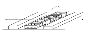
図1を参照して、本発明の所定情報を表わすレリーフ型回折格子の一例について説明する。
図1の回折格子線は、所定の文字、記号、図柄の何れか、または、これらの組み合わせ情報(以下所定情報という)を表示する一列の凹凸構造からなる所定情報を表わす、一列の凹凸構造からなる。この所定情報は、任意の文字、記号、図柄の何れか、または、これらの組み合わせ情報とすることができる。凹凸構造形成方法もサブミクロン加工(1μm以下のパターン加工)が可能な微細加工方法のいずれをも採用することができる。
Hereinafter, embodiments of the present invention will be described in detail with reference to the drawings.
With reference to FIG. 1, an example of a relief type diffraction grating representing predetermined information of the present invention will be described.
The diffraction grating lines in FIG. 1 represent a predetermined information consisting of a single line of concave / convex structure that displays any one of predetermined characters, symbols, designs, or combination information thereof (hereinafter referred to as predetermined information). Become. The predetermined information may be any character, symbol, or design, or combination information thereof. As the concavo-convex structure forming method, any of fine processing methods capable of submicron processing (pattern processing of 1 μm or less) can be adopted.
図1の例(レリーフ型回折格子A)では、の回折格子線群のL/Sを6/4(周期1.0μm(L:0.6μm、S:0.4μm)とし、特定回折格子線の所定情報として「HHH・・」という文字が設定されている。文字の高さ・幅は、0.6μm×0.5μm(周期1.0μm)であり、これは、電子線リソグラフィーにより形成できる。電子線レジストの厚さを0.3μmとし、現像処理をすることで、凹凸を有するレリーフ原盤を形成することができる。 In the example of FIG. 1 (relief-type diffraction grating A), L / S of the diffraction grating line group is 6/4 (period 1.0 μm (L: 0.6 μm, S: 0.4 μm)), and specific diffraction grating lines. The character “HHH...” Is set as the predetermined information of the character, and the height and width of the character is 0.6 μm × 0.5 μm (period 1.0 μm), which can be formed by electron beam lithography. A relief master having irregularities can be formed by developing the electron beam resist to a thickness of 0.3 μm.
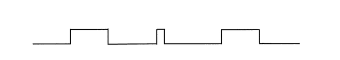
このレリーフ原盤のa―a断面をみると、図2のように回折格子線群の断面は単純な矩形となっており、一本形成した特定回折格子線の断面は凸部が所定情報により複雑な矩形を呈している。この凸部面積と凹部面積の比がどちらも6/4となっている。
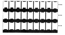
図3は、レリーフ型回折格子Aを上から見た図である。
これと同様に、同一所定情報の配列にて、周期、L/S比及び文字高さ・幅が、周期1.25μm、6/4、0.75μm×0.6μm、及び周期1.5μm、6/4、0.90μm×0.7μmの回折格子線群及び特定回折格子線を形成し、それぞれを図4の3つのエリア(B1、B2、B3)に配置して円形のレリーフ型回折格子体Bの原盤を作成できる。
Looking at the aa cross section of the relief master, the cross section of the diffraction grating line group is a simple rectangle as shown in FIG. 2, and the convex section of the cross section of the single specific diffraction grating line formed is complicated by predetermined information. A rectangular shape. The ratio of the convex area to the concave area is 6/4.
FIG. 3 is a view of the relief type diffraction grating A as viewed from above.
Similarly, in the same predetermined information array, the period, the L / S ratio, and the character height / width are the period 1.25 μm, 6/4, 0.75 μm × 0.6 μm, and the period 1.5 μm, 6/4, 0.90 μm × 0.7 μm diffraction grating line group and specific diffraction grating lines are formed and arranged in the three areas (B1, B2, B3) of FIG. The master of body B can be created.
これら回折格子線群のレリーフ周期や、レリーフ深さ(図2における高さ)を調節することにより、観察したときの色調や明るさ(光の強度)を制御することができ、また、各回折格子線群の配置方法等(回折格子線群の占有する形、面積及び点在させる方法等)を工夫することにより、複雑なデザインの回折格子や、カラーホログラムを形成することができる。すなわち、所定のエリアに、同一のピッチ、同一の角度を持つ回折格子線群を埋めてエリア毎の回折格子線群を形成し、個々のエリアには、所定の面積、所定のピッチ、角度が割り当てられていて、全エリアを白色光で観察すると、カラーホログラムを観察することができる。 By adjusting the relief period and relief depth (height in FIG. 2) of these diffraction grating lines, the color tone and brightness (light intensity) when observed can be controlled, and each diffraction By devising the arrangement method of the grating line group (the shape occupied by the diffraction grating line group, the area, the method of interspersing, etc.), it is possible to form a diffraction grating with a complicated design or a color hologram. That is, a diffraction grating line group having the same pitch and the same angle is filled in a predetermined area to form a diffraction grating line group for each area, and each area has a predetermined area, a predetermined pitch, and an angle. When assigned and observing the entire area with white light, a color hologram can be observed.
次に、上記した回折格子原盤を用いて、シート状のレリーフ型回折格子又はホログラムを作成する方法を述べる。
透明基材として、厚みを薄くすることが可能であって、機械的強度や、レリーフ型回折格子又はホログラムシート、ラベル、及び転写シートを製造する際の加工に耐える耐溶剤性および耐熱性を有するものを使用する。使用目的にもよるので、限定されるものではないが、フィルム状もしくはシート状のプラスチックが好ましい。
Next, a method for producing a sheet-like relief type diffraction grating or hologram using the above-described diffraction grating master will be described.
As a transparent substrate, it is possible to reduce the thickness, and it has mechanical strength and solvent resistance and heat resistance that can withstand processing when manufacturing a relief type diffraction grating or hologram sheet, label, and transfer sheet. Use things. Since it depends on the purpose of use, it is not limited, but a film-like or sheet-like plastic is preferable.
例えば、ポリエチレンテレフタレート(PET)、ポリカーボネート、ポリビニルアルコール、ポリスルホン、ポリエチレン、ポリプロピレン、ポリスチレン、ポリアリレート、トリアセチルセルロース(TAC)、ジアセチルセルロース、ポリエチレン/ビニルアルコール等の各種のプラスチックフィルムを例示することができる。
透明基材の厚さは、同様の配慮から、5〜50μm、特に5〜15μmとすることが望ましい。転写シートを形成する際、透明基材1に、通常用いられる酢酸セルロース樹脂やメタクリル樹脂等からなる剥離層を設けても良い。
For example, various plastic films such as polyethylene terephthalate (PET), polycarbonate, polyvinyl alcohol, polysulfone, polyethylene, polypropylene, polystyrene, polyarylate, triacetyl cellulose (TAC), diacetyl cellulose, and polyethylene / vinyl alcohol can be exemplified. .
From the same consideration, the thickness of the transparent substrate is desirably 5 to 50 μm, particularly 5 to 15 μm. When forming the transfer sheet, the transparent substrate 1 may be provided with a release layer made of a commonly used cellulose acetate resin, methacrylic resin or the like.
レリーフ型回折格子やホログラムを形成する層(以下ホログラム形成層という。)を構成するための透明な樹脂材料としては、各種の熱可塑性樹脂、熱硬化性樹脂、もしくは電離放射線硬化性樹脂を用いることができる。熱可塑性樹脂としてはアクリル酸エステル樹脂、アクリルアミド樹脂、ニトロセルロース樹脂、もしくはポリスチレン樹脂等が、また、熱硬化性樹脂としては、不飽和ポリエステル樹脂、アクリルウレタン樹脂、エポキシ変性アクリル樹脂、エポキシ変性不飽和ポリエステル樹脂、アルキッド樹脂、もしくはフェノール樹脂等が挙げられる。 Various thermoplastic resins, thermosetting resins, or ionizing radiation curable resins may be used as a transparent resin material for constituting a relief type diffraction grating or a hologram forming layer (hereinafter referred to as a hologram forming layer). Can do. Thermoplastic resins include acrylic ester resins, acrylamide resins, nitrocellulose resins, or polystyrene resins. Thermosetting resins include unsaturated polyester resins, acrylic urethane resins, epoxy-modified acrylic resins, and epoxy-modified unsaturated resins. A polyester resin, an alkyd resin, a phenol resin, etc. are mentioned.
これらの熱可塑性樹脂および熱硬化性樹脂は、1種もしくは2種以上を使用することができる。これらの樹脂の1種もしくは2種以上は、各種イソシアネート樹脂を用いて架橋させてもよいし、あるいは、各種の硬化触媒、例えば、ナフテン酸コバルト、もしくはナフテン酸亜鉛等の金属石鹸を配合するか、または、熱もしくは紫外線で重合を開始させるためのベンゾイルパーオキサイド、メチルエチルケトンパーオキサイド等の過酸化物、ベンゾフェノン、アセトフェノン、アントラキノン、ナフトキノン、アゾビスイソブチロニトリル、もしくはジフェニルスルフィド等を配合しても良い。 These thermoplastic resins and thermosetting resins can be used alone or in combination of two or more. One or more of these resins may be cross-linked using various isocyanate resins, or various curing catalysts, for example, metal soap such as cobalt naphthenate or zinc naphthenate may be blended. Or peroxide such as benzoyl peroxide and methyl ethyl ketone peroxide for initiating polymerization with heat or ultraviolet light, benzophenone, acetophenone, anthraquinone, naphthoquinone, azobisisobutyronitrile, or diphenyl sulfide good.
また、電離放射線硬化性樹脂としては、エポキシアクリレート、ウレタンアクリレート、アクリル変性ポリエステル等を挙げることができ、このような電離放射線硬化性樹脂に架橋構造を導入するか、もしくは粘度を調整する目的で、単官能モノマーもしくは多官能モノマー、またはオリゴマー等を配合して用いてもよい。微細な凹凸を精密に複製するためには、この粘度を0.001〜0.1パスカル秒とすると好適である。 Examples of the ionizing radiation curable resin include epoxy acrylate, urethane acrylate, acrylic-modified polyester, etc., for the purpose of introducing a crosslinked structure into such an ionizing radiation curable resin or adjusting the viscosity, A monofunctional monomer, a polyfunctional monomer, or an oligomer may be blended and used. In order to accurately reproduce fine irregularities, it is preferable that the viscosity is 0.001 to 0.1 Pascal second.
熱硬化性樹脂や電離放射線硬化性樹脂を用いる場合には、型面に未硬化の樹脂を密着させたまま、加熱もしくは電離放射線照射により、硬化を行わせ、硬化後に剥離することによって、硬化した透明な樹脂材料からなる層の片面にレリーフホログラムの微細凹凸を形成することができる。この方法によれば、0.01μm程度の微細な凹凸変化も精密に複製することができる。なお、同様な方法によりパターン状に形成して模様状としたレリーフ型回折格子を有するレリーフ型回折格子形成層も光回折構造として使用できる。 When thermosetting resin or ionizing radiation curable resin is used, curing is performed by heating or ionizing radiation irradiation while keeping the uncured resin in close contact with the mold surface, and then cured by peeling after curing. The fine irregularities of the relief hologram can be formed on one side of the layer made of a transparent resin material. According to this method, a minute unevenness change of about 0.01 μm can be accurately replicated. A relief type diffraction grating forming layer having a relief type diffraction grating formed into a pattern by a similar method can also be used as the optical diffraction structure.
このような微細な形状を精密に再現するため、また、複製後の熱収縮などの歪みや変形を最小とするため、低温・高圧下で複製を行うこともできる。
この場合、複製方式は、平板式もしくは、回転式を用い、線圧0.1トン/m〜10トン/m、複製温度は、通常60℃〜200℃とすることが好適である。
In order to accurately reproduce such a fine shape and to minimize distortion and deformation such as heat shrinkage after replication, replication can be performed at low temperature and high pressure.
In this case, it is preferable that the duplication method is a flat plate type or a rotary type, the linear pressure is 0.1 ton / m to 10 ton / m, and the duplication temperature is usually 60 ° C. to 200 ° C.
さらに、ホログラム形成層のホログラムレリーフ面に、一部または全面に反射性薄膜層を形成する。この薄膜は、入射した光を反射する必要があるため、ホログラム形成層よりも高い屈折率を有する薄膜であれば、特に限定されない。
反射性薄膜としては、真空薄膜法などにより形成される金属薄膜などの金属光沢反射層、又は透明反射層のいずれでもよいが、金属光沢反射層を部分的に設けたり、透明反射層を設けた場合は、その反射層に接して設けたセキュリティ対象物をこの透明反射層を通して確認できるので好ましい。
Further, a reflective thin film layer is formed on part or all of the hologram relief surface of the hologram forming layer. Since this thin film needs to reflect incident light, it is not particularly limited as long as it is a thin film having a higher refractive index than the hologram forming layer.
The reflective thin film may be either a metallic gloss reflective layer such as a metal thin film formed by a vacuum thin film method or a transparent reflective layer, but a metallic gloss reflective layer is provided partially or a transparent reflective layer is provided. In this case, it is preferable because the security object provided in contact with the reflective layer can be confirmed through the transparent reflective layer.
透明反射層としては、ほぼ無色透明な色相で、その光学的な屈折率がホログラム形成層のそれとは異なることにより、金属光沢が無いにもかかわらず、ホログラムなどの光輝性を視認できることから、透明なホログラムを作製することができる。例えば、ホログラム形成層よりも光屈折率の高い薄膜、例として、ZnS、TiO2、Al2O3、Sb2S3、SiO、SnO2、ITOなどがある。 As a transparent reflective layer, it is almost colorless and transparent, and its optical refractive index is different from that of the hologram forming layer. A simple hologram can be produced. For example, a thin film having a higher refractive index than that of the hologram forming layer, for example, ZnS, TiO 2 , Al 2 O 3 , Sb 2 S 3 , SiO, SnO 2 , ITO, etc.
好ましくは、金属酸化物又は窒化物であり、具体的には、Be、Mg、Ca、Cr、Mn、Cu、Ag、Al、Sn、In、Te、Ti、Fe、Co、Zn、Ge、Pb、Cd、Bi、Se、Ga、Rb、Sb、Pb、Ni、Sr、Ba、La、Ce、Auなどの酸化物又は窒化物他はそれらを2種以上を混合したものなどが例示できる。またアルミニウムなどの一般的な光反射性の金属薄膜も、厚みが20nm以下になると、透明性が出てきて透明反射層として使用できる。 Preferably, it is a metal oxide or nitride, specifically, Be, Mg, Ca, Cr, Mn, Cu, Ag, Al, Sn, In, Te, Ti, Fe, Co, Zn, Ge, Pb. Cd, Bi, Se, Ga, Rb, Sb, Pb, Ni, Sr, Ba, La, Ce, Au, and other oxides or nitrides, and the like can be exemplified by a mixture of two or more thereof. Also, a general light-reflective metal thin film such as aluminum can be used as a transparent reflective layer when it has a thickness of 20 nm or less and becomes transparent.
透明金属化合物の形成は、金属の薄膜と同様、ホログラム形成層のホログラムレリーフ面に、10〜2000nm程度、好ましくは20〜1000nmの厚さになるよう、蒸着、スパッタリング、イオンプレーティング、CVD(化学蒸着法)などの真空薄膜法などにより設ければよい。微細な凹凸を忠実に覆うには、特にCVDが好適である。但し、レリーフホログラムに接している面からの反射光だけでなく、反対面での反射光で同様の再生画像を得るためには、薄膜の凹凸をレリーフホログラムと同様の形状にする必要があり、上記薄膜の厚さを10nm程度とする。 As with the metal thin film, the transparent metal compound is formed by vapor deposition, sputtering, ion plating, CVD (chemical) on the hologram relief surface of the hologram forming layer so as to have a thickness of about 10 to 2000 nm, preferably 20 to 1000 nm. It may be provided by a vacuum thin film method such as a vapor deposition method. In order to faithfully cover fine irregularities, CVD is particularly suitable. However, in order to obtain the same reproduced image not only with the reflected light from the surface in contact with the relief hologram but also with the reflected light on the opposite surface, it is necessary to make the unevenness of the thin film the same shape as the relief hologram, The thickness of the thin film is about 10 nm.
レリーフ型回折格子又はホログラムは、転写形態で使用する場合は、上記反射層の上に、感熱接着剤層を形成して転写用フィルムと成し、熱せられた金属の型等によって、接着剤層を含めた極めて薄い樹脂層をセキュリティ対象物上に転写して使用する。
レリーフ型回折格子又はホログラムをラベル形態で使用する場合は、上記反射層の上に粘着剤層を形成し、粘着剤面を剥離紙で被覆して、基材フィルムを剥離紙と一緒に所定の大きさに打ち抜いてラベルとし、剥離紙を剥がしてセキュリティ対象物に貼付して使用する。
When the relief type diffraction grating or hologram is used in a transfer form, a heat-sensitive adhesive layer is formed on the reflective layer to form a transfer film, and the adhesive layer is formed by a heated metal mold or the like. A very thin resin layer including is transferred onto a security object and used.
When a relief type diffraction grating or hologram is used in the form of a label, an adhesive layer is formed on the reflective layer, the adhesive surface is covered with a release paper, and the base film is put together with the release paper in a predetermined manner. It is punched into a size to make a label, and the release paper is peeled off and attached to a security object for use.
もちろん、本発明のレリーフ型回折格子又はホログラムが、その意匠性や、偽造防止性だけでなく、セキュリティ対象物の唯一の真正性証明手段ということであれば、セキュリティ対象物から容易に剥離可能であってはならず、セキュリティ対象物を成形加工する際に本発明のレリーフ型回折格子又はホログラムを一体成形として埋め込んだり、本発明の格子又はホログラムを剥離しようとした時、セキュリティ対象物もしくは、本発明のレリーフ型回折格子又はホログラムそのものが破壊される等、セキュリティ対象物と一体不可分として、さらに偽造防止性を高めることが望ましい。 Of course, if the relief type diffraction grating or hologram of the present invention is not only the design property and anti-counterfeiting property, but also the only authenticity proof means for the security object, it can be easily peeled from the security object. When the security object is molded, the relief type diffraction grating or hologram of the present invention is embedded as an integral molding, or the security object or the present It is desirable to further improve anti-counterfeiting as an integral part of the security object such that the relief type diffraction grating or the hologram itself of the invention is destroyed.
所定情報は、任意でよく、ランダムなものであっても(ランダム数字発生器により発生したランダム数字など)、同一文字・記号・図柄の繰り返しとしてもよく、(その場合は回折効率の計算が容易となる)、目視では確認困難な情報として組み込む情報であるため、セキュリティ用途として採用された上記カラーホログラム画像としての各種絵柄に関連する情報や、このカラーホログラム画像が転写もしくは貼付されるセキュリティ対象物に関連する情報もしくは、関連する商品や、その商品を提供する会社の名称、マーク等、本発明のレリーフ型回折格子又はホログラムの真正性を証明できる情報を盛り込むこともできる。 The predetermined information may be arbitrary, may be random (such as a random number generated by a random number generator), or may be the same letter / symbol / design repeated (in this case, the diffraction efficiency can be easily calculated). Because it is information that is incorporated as information that is difficult to confirm visually, information related to various patterns as the color hologram image adopted for security applications, and security objects to which this color hologram image is transferred or pasted Or information relating to the relief diffraction grating or hologram of the present invention, such as the name of the company providing the product, the name of the company providing the product, or a mark, can be included.
上記例では、所定情報幅を0.5μm〜0.7μmとしたが、この幅に制限はなく任意に設定できる。例えば、回折格子線の端から橋まで一つの文字・記号・図柄であってもよく、例えばカラーホログラム画像の端から端まで、途中の回折格子線の途切れに関係なく、情報として、つながっているものであっても良い。
この所定情報は、目視や簡易顕微鏡では判別できないため、真正性を確認するためには
倍率の高い精密顕微鏡を用いてその情報を読み出し、「正規な情報」(所定情報を実際に物理的形状として形成した時の、真正であると判定するための情報。所定情報そのものだけでなく、形状等の情報を含めても良い。また、所定情報でなく、その形状を測定したデータ等や、部分的に変形した情報等を用いても良い。)か否かを判定する必要がある。
In the above example, the predetermined information width is 0.5 μm to 0.7 μm, but this width is not limited and can be arbitrarily set. For example, it may be a single character, symbol, or pattern from the end of the diffraction grating line to the bridge. For example, from the end of the color hologram image to the end, it is connected as information regardless of the interruption of the diffraction grating line on the way. It may be a thing.
Since this predetermined information cannot be discriminated by visual observation or a simple microscope, in order to confirm the authenticity, the information is read using a high-precision microscope, and “regular information” (the predetermined information is actually converted into a physical shape). Information for determining authenticity at the time of formation, which may include not only the predetermined information itself but also information such as the shape, etc. In addition to the predetermined information, the data obtained by measuring the shape, etc. It may be necessary to determine whether or not the information transformed into the above may be used.
真正性の判定者は、判定を行う時には、「正規な情報」に関する正確な知識を有する必要があるが、上記したようにカラーホログラム画像としての各種絵柄やセキュリティ対象物等に関する情報であれば、特段の照会等を必要とせず、判定者へ「関連情報が隠し文字として入っている。」程度の申し送りを事前にしておくことで、簡易に真正と類推することができる。もしくは、隠し文字の特徴の一部のみを申し送りして置く方法も使用できる。 The authenticator needs to have accurate knowledge about "regular information" when making a determination, but as described above, if it is information about various designs or security objects as a color hologram image, No special inquiry or the like is required, and it can be easily inferred to be authentic by preliminarily sending the judgment person about “related information is included as hidden characters”. Alternatively, it is also possible to use a method in which only a part of the hidden character feature is sent and placed.
もちろん、「真正性を鑑定する場合」(偽造品が真正品かの判定を何らかの証拠に用いる場合等、より信頼性の高い判定をする場合。)には、「正規な情報」として、例えば、文字、記号、図柄の情報だけでなく、そのサイズ、画線部の太さ、凹凸の高さ等、より多くの情報を設定し、その全てを確認することが好適である。
所定情報の「正規な情報」をデータで残す方法として、高解像度のレーザー顕微鏡による3次元形状情報を取得しておき、このデータと、鑑定のために測定した「真正性を確認するもの」のデータを照合し、「50%以上の一致」あるいは照合項目によっては「100%の一致」等のある程度の一致をもって「真正」と判断する方法を使用することも好適である。
Of course, when “authenticating authenticity” (when determining whether a counterfeit product is authentic, for example, when making a more reliable determination, such as when using some evidence), as “regular information”, for example, It is preferable to set not only information on characters, symbols, and designs but also more information such as the size, the thickness of the image portion, the height of the unevenness, and confirm all of them.
As a method of leaving the “regular information” of the predetermined information in the data, the three-dimensional shape information obtained by a high-resolution laser microscope is acquired, and this data and the “confirm authenticity” measured for the appraisal It is also preferable to use a method of collating data and determining “authentic” with a certain degree of coincidence such as “100% coincidence” or “100% coincidence” depending on the collation item.
これらの「正規な情報」は、真正性を鑑定する鍵となる情報であるため、物理的もしくは電子的に、セキュリティレベルの高い場所(物理的もしくは電子的)に保存、保管することが望ましい。もちろん、DES(Data Encryption Standard。暗号化方式の規格)やAES(Advanced Encryption Standard。同左。)等による暗号化を施してもよい。その場合は、共通鍵方式や、さらに秘匿性の高い公開鍵方式等の種々の鍵管理方式を併用し、複数の鑑定者へ鍵情報を秘匿性を維持しつつ提供することも好適である。 Since these “regular information” are key information for authenticating authenticity, it is desirable to store and store them physically or electronically in a place with high security level (physical or electronic). Of course, encryption by DES (Data Encryption Standard), AES (Advanced Encryption Standard, same as the left) or the like may be performed. In that case, it is also preferable to provide key information to a plurality of appraisers while maintaining the confidentiality by using various key management methods such as a common key method and a public key method with higher confidentiality.
単純な例では、所定の用紙に書いて、金庫等に保管してもよいし、電子データとして、アクセス制限(パスワード設定等)されたサーバーの所定のホルダに記録しておき、数人程度に限定した人のみが読み出しできるように、ホルダを読み出す際にも、パスワード入力を要求するシステムとしても良い。いずれにしても、正規な情報の秘匿性のレベルに対応し、且つ、可用性(使いやすさ)を考慮して管理方式を定めることが求められる。 In a simple example, it may be written on a predetermined sheet and stored in a safe or the like, or recorded as electronic data in a predetermined holder of a server that is restricted in access (password setting, etc.) The system may require a password input when reading the holder so that only a limited person can read it. In any case, it is required to define a management method in consideration of the level of confidentiality of legitimate information and considering availability (ease of use).
また、所定情報を回折格子線の途中で変更したり、回折格子線群のピッチ(周期)、角度を変えた時に変更することも偽造防止性を高めるために好適である。さらには、回折格子線群のピッチ、角度が同一のエリアにある回折格子線は、エリアとエリアの間のブランクに無関係に、「一続き」(ブランクがなく続いていると想定したときの並びを意味する)の所定情報を形成したものであってもよい。 It is also preferable to change the predetermined information in the middle of the diffraction grating line or to change it when the pitch (period) or angle of the diffraction grating line group is changed in order to improve the forgery prevention property. Furthermore, the diffraction grating lines in the area where the pitch and angle of the diffraction grating line group are the same are “continuous” (arranged assuming that there is no blank, regardless of the blank between the areas). The predetermined information may be formed.
こうすることで、全く「同一のもの」を偽造しようとする者が、本発明のレリーフ型回折格子又はホログラムの全ての回折格子線の全ての所定情報を解読しない限り、「同一のもの」を偽造することができない状況とすることができる。
もちろん、回折格子線群毎に、所定情報を変更してもよいが、この場合は、所定情報毎の回折効率を考慮した配置とする必要がある。
In this way, unless the person who tries to counterfeit the “same thing” completely decodes all the predetermined information of all the diffraction grating lines of the relief type diffraction grating or hologram of the present invention, It can be a situation that cannot be counterfeited.
Of course, the predetermined information may be changed for each diffraction grating line group, but in this case, it is necessary to arrange the diffraction efficiency for each predetermined information.
所定情報や、その凹凸形状に関する情報は、実際の絵柄としての情報や、凹凸設計情報、さらには各リソグラフィー形成情報(電子線リソグラフィーでは、電子線描画プログラム等)により真正性証明情報として保有できる。もちろん、回折格子線のピッチ、角度等の情報も同様である。
凹凸構造形成方法としては、上記した電子線リソグラフィー、X線リソグラフィー等の高精度なパターンを形成することができるリソグラフィー法のみならず、金属薄膜形成法等の高精度な均一膜厚さを形成することができる各種薄膜形成方法とそのパターン化方法を組み合わせる方法等を用いることができる。
Predetermined information and information on the uneven shape can be held as authenticity proof information by information as an actual pattern, uneven design information, and each lithography formation information (in electron beam lithography, an electron beam drawing program or the like). Of course, the same applies to information such as the pitch and angle of the diffraction grating lines.
As a method for forming the concavo-convex structure, not only a lithography method capable of forming a high-precision pattern such as the electron beam lithography and X-ray lithography described above, but also a high-precision uniform film thickness such as a metal thin film formation method is formed. Various thin film forming methods that can be used and methods for combining the patterning methods can be used.
レリーフ型回折格子Aの回折効率は、図3のレリーフ型回折格子体Bのそれぞれのエリア(B1、B2、B3)を、それぞれの光源、周期1.0μmのエリア、周期1.25μmのエリア、周期1.5μmのエリアを、対応する半導体レーザーで測定したところ、それぞれ、14%、15%、15%であった。レリーフ型回折格子体B全体を、全光源で照明したところ、それぞれのエリアが、それぞれの画像に分かれて鮮やかに観察された。 The diffraction efficiency of the relief type diffraction grating A is as follows: the respective areas (B1, B2, B3) of the relief type diffraction grating B in FIG. 3 are each light source, an area with a period of 1.0 μm, an area with a period of 1.25 μm, When an area with a period of 1.5 μm was measured with a corresponding semiconductor laser, they were 14%, 15%, and 15%, respectively. When the entire relief type diffraction grating B was illuminated with all light sources, each area was divided into each image and observed vividly.
また、隠し文字としての「HHH・・」は、目視ではもちろんのこと、簡易顕微鏡(倍率200倍、400倍)で判読しようとしたが、文字・記号まで読み取ることは出来なかった。しかし、所定の設定調整を施した高解像度レーザー顕微鏡では明確に判読できた。
もちろん、これより解像度の高い顕微鏡、例えば、共焦点レーザー顕微鏡 、電子顕微鏡
透過型電子顕微鏡 、走査型電子顕微鏡、走査型プローブ顕微鏡 、原子間力顕微鏡、走査型トンネル顕微鏡 、走査型近接場光顕微鏡 、X線顕微鏡等、物理的に測定が可能なように対応できる範囲で利用できる。さらに、共焦点法や、位相シフト干渉法等の解像度を向上する手法も利用できる。これらの顕微鏡映像を高解像度CCDカメラ等を用いた画像処理方法により、画像を精密につなぎ合わせて、広範囲のエリアに対する情報とすることもできる。
In addition, “HHH...” As a hidden character was read with a simple microscope (magnification 200 ×, 400 ×) as well as visually, but it was not possible to read even the character / symbol. However, it was clearly readable with a high-resolution laser microscope that had been adjusted to the specified setting.
Of course, higher resolution microscopes such as confocal laser microscopes, electron microscopes, transmission electron microscopes, scanning electron microscopes, scanning probe microscopes, atomic force microscopes, scanning tunneling microscopes, scanning near-field light microscopes, It can be used in a range that can be physically measured, such as an X-ray microscope. Furthermore, techniques for improving resolution such as confocal method and phase shift interferometry can also be used. By using an image processing method using a high-resolution CCD camera or the like for these microscopic images, the images can be joined together precisely to obtain information for a wide area.
但し、「真正性」判定(もしくは鑑定)をする手法は、上記した「多くの所定情報を読み出す方法」にこだわらず、一つの文字、記号や図柄もしくはさらにその一部に注目し、この一つの文字、記号や図柄もしくはさらにその一部を「精密に測定」して、その立体形状のみを「真正性」判定に使用する方法も用いることができる。
この場合、注目した部分を全て同一のものとせず、少し変形(太さを2倍としたり、欠陥を付加したりする。)しておき、それらの情報を、「真正性」判定用に使用することができる。すなわち、「真正性」判定に使用する情報は、セキュリティ管理をする側が定めることができ(その任意性がさらに偽造防止性を高める。)、偽造者からは到底類推できないものとすることが可能となる。
However, the method for determining (or appraising) “authenticity” is not limited to the above-mentioned “method of reading a large amount of predetermined information”, but paying attention to one character, symbol, symbol or part thereof, and this one It is also possible to use a method in which characters, symbols, symbols or parts thereof are “precisely measured” and only the three-dimensional shape is used for “authenticity” determination.
In this case, do not make all the focused parts the same, but slightly deform (double the thickness or add a defect) and use the information for “authenticity” determination can do. In other words, the information used for the “authenticity” determination can be determined by the security management side (the voluntary nature further enhances the anti-counterfeiting property), and it can be assumed that the counterfeiter cannot make any analogy. Become.
本発明の所定情報を表わすレリーフ型回折格子の別の例について説明する。
上記した例のレリーフ回折格子のL/S比を1/1として以下全て同様に作製し、レリーフ型回折格子A、及びレリーフ型回折格子体Bを得ることができる。
Another example of the relief type diffraction grating representing the predetermined information of the present invention will be described.
Relief type diffraction grating A and relief type diffraction grating B can be obtained in the same manner by setting the L / S ratio of the relief diffraction grating of the above-mentioned example to 1/1.
上記レリーフ型回折格子Aの回折効率は、上記レリーフ型回折格子体Bのそれぞれのエリア(B1、B2、B3)を、それぞれの光源、周期1.0μmのエリア、周期1.25μmのエリア、周期1.5μmのエリアを、対応する半導体レーザーで測定したところ、それぞれ、18%、19%、19%であった。上記レリーフ型回折格子体B全体を、全光源で照明したところ、それぞれのエリアが、それぞれの画像に分かれて鮮やかに観察された。 The diffraction efficiency of the relief type diffraction grating A is as follows: the respective areas (B1, B2, B3) of the relief type diffraction grating body B are each light source, an area having a period of 1.0 μm, an area having a period of 1.25 μm, and a period. When the area of 1.5 μm was measured with the corresponding semiconductor laser, they were 18%, 19%, and 19%, respectively. When the entire relief type diffraction grating B was illuminated with all light sources, each area was divided into each image and observed vividly.
(実施例1)
電子線レジストを0.3μm形成したパターン形成基盤に、予め用意した制御データにより、電子ビームの強度を変化させながら所定のレリーフ型回折格子パターンに沿って電子ビームを照射した。回折格子線群は、周期1.0μm、L/Sが6/4とし、特定回折格子線は、0.6μm幅の線上に、所定情報「HHH・・」、及びその繰り返し」を各文字サイズが、0.6μm×0.5μmとなるように照射した。
これと同様に、同一所定情報の配列にて、周期、L/S比及び文字高さ・幅が、周期1.25μm、6/4、0.75μm×0.6μm、及び周期1.5μm、6/4、0.90μm×0.7μmの回折格子線群及び特定回折格子線を形成すべく、それぞれを図3の3つのエリア(B1、B2、B3)が埋まるまで実施した。
この基盤を現像処理して、所望の凹凸レリーフ原盤を得た。
Example 1
An electron beam was irradiated along a predetermined relief type diffraction grating pattern while changing the intensity of the electron beam according to control data prepared in advance on a pattern formation substrate on which an electron beam resist was formed to 0.3 μm. The diffraction grating line group has a period of 1.0 μm, L / S is 6/4, and the specific diffraction grating line has a predetermined information “HHH... And its repetition” on a 0.6 μm width line. However, it irradiated so that it might become 0.6 micrometer x 0.5 micrometer.
Similarly, in the same predetermined information array, the period, the L / S ratio, and the character height / width are the period 1.25 μm, 6/4, 0.75 μm × 0.6 μm, and the period 1.5 μm, In order to form 6/4, 0.90 μm × 0.7 μm diffraction grating line groups and specific diffraction grating lines, each was carried out until the three areas (B1, B2, B3) in FIG. 3 were filled.
The substrate was developed to obtain a desired uneven relief master.
この原盤と、16μm厚さのポリエチレンテレフタレート(東レ製「ルミラー」)との間に、電離放射線硬化性樹脂として、
・<電離放射線硬化組成物A>
2−ヒドロキシエチルアクリレート 100重量部
ジブチルチンジラウリレート 0.1重量部
イソシアン酸メチル 50重量部
を反応させて得られた電離放射線硬化組成物Aを用いて、
・<電離放射線硬化組成物B>
電離放射線硬化組成物A 80重量部
ポリウレタン樹脂(デスモコール130、住友バイエルウレタン社製) 20重量部
上記、電離放射線硬化組成物Bを作製し、この電離放射線硬化組成物Bを10μm導入して、フィルムを送り出しながら電子線照射装置「エレクトロカーテン」(アメリカのESI社製)を用い、150KeV、15mAの条件で3Mradの線量を照射して、硬化させた。
Between this master and 16 μm thick polyethylene terephthalate (Toray “Lumilar”), as ionizing radiation curable resin,
・ <Ionizing radiation curable composition A>
2-hydroxyethyl acrylate 100 parts by weight Dibutyltin dilaurate 0.1 part by weight Ionizing radiation curable composition A obtained by reacting methyl isocyanate 50 parts by weight,
・ <Ionizing radiation curable composition B>
Ionizing radiation curable composition A 80 parts by weight Polyurethane resin (Desmocol 130, manufactured by Sumitomo Bayer Urethane Co., Ltd.) 20 parts by weight The above ionizing radiation curable composition B was prepared, and 10 μm of this ionizing radiation curable composition B was introduced. While sending out the film, an electron beam irradiation apparatus “Electro Curtain” (manufactured by ESI, USA) was used to irradiate with a dose of 3 Mrad under the conditions of 150 KeV and 15 mA to be cured.
この後、原盤と電子線レジストを剥離、除去し、硬化した透明な樹脂材料からなる層の片面にレリーフホログラムの微細凹凸を形成することができた。
この透明樹脂の表面に真空蒸着法によりアルミニウム薄膜100nmを形成し、ホログラムシートとした。このホログラムシートに接着剤を塗工し、パスポートの顔写真を一部覆うように接着した。
このパスポートのホログラム部分をハロゲンランプで照明し、目視で観察すると、円形ホログラムが3色に分かれて鮮明に見えた。さらに、倍率20倍と400倍の顕微鏡で拡大して確認したところ、所定情報を判読することは出来なかった。
After that, the master and the electron beam resist were peeled off and removed, and the fine irregularities of the relief hologram could be formed on one side of the layer made of a cured transparent resin material.
An aluminum thin film having a thickness of 100 nm was formed on the surface of the transparent resin by a vacuum deposition method to obtain a hologram sheet. An adhesive was applied to the hologram sheet and adhered so as to partially cover the face photograph of the passport.
When the hologram portion of this passport was illuminated with a halogen lamp and visually observed, the circular hologram was divided into three colors and looked clear. Furthermore, when it was enlarged and confirmed with a microscope with a magnification of 20 times and 400 times, predetermined information could not be read.
このホログラム部分を高解像度レーザー顕微鏡で観察することで、各レリーフ型回折格子の所定情報を判読することができ、予め極秘情報として入手した(パスポートを管理する関係者のみが所定情報のサイズ、並び等の情報(以下、所定情報関連情報という。)を知らされるという意味。)所定情報関連情報と、判読した情報を比較し、パスポートの真正性を確認した。
別途、このホログラムの回折効率を対応する半導体レーザーを用いて測定したところ、それぞれ、14%、15%、15%であり、高い回折効率を得た。
By observing this hologram portion with a high-resolution laser microscope, it is possible to read the predetermined information of each relief type diffraction grating, and obtained in advance as top secret information (only the person who manages the passport has the size and arrangement of the predetermined information) Etc. (hereinafter referred to as “predetermined information related information”). The passport authenticity was confirmed by comparing the predetermined information related information with the read information.
Separately, when the diffraction efficiency of this hologram was measured using a corresponding semiconductor laser, it was 14%, 15%, and 15%, respectively, and high diffraction efficiency was obtained.
(実施例2)
電子線レジストを0.3μm形成したパターン形成基盤に、予め用意した制御データにより、電子ビームの強度を変化させながら所定のレリーフ型回折格子パターンに沿って電子ビームを照射した。
L/S比を1/1とした以外は全て実施例1と同様とし、レリーフ型回折格子体B及びそれを適用したパスポートを得た。
このパスポートのホログラム部分をハロゲンランプで照明し、目視で観察すると、円形ホログラムが3色に分かれて鮮明に見えた。さらに、倍率20倍と400倍の顕微鏡で拡大して確認したところ、所定情報を判読することは出来なかった。
(Example 2)
An electron beam was irradiated along a predetermined relief type diffraction grating pattern while changing the intensity of the electron beam according to control data prepared in advance on a pattern formation substrate on which an electron beam resist was formed to 0.3 μm.
Except for setting the L / S ratio to 1/1, everything was the same as in Example 1, and a relief type diffraction grating B and a passport to which it was applied were obtained.
When the hologram portion of this passport was illuminated with a halogen lamp and visually observed, the circular hologram was divided into three colors and looked clear. Furthermore, when it was enlarged and confirmed with a microscope with a magnification of 20 times and 400 times, predetermined information could not be read.
このホログラム部分を高解像度レーザー顕微鏡で観察することで、各レリーフ型回折格子の所定情報を判読することができ、予め極秘情報として入手した(パスポートを管理する関係者のみが所定情報のサイズ、並び等の情報(以下、所定情報関連情報という。)を知らされるという意味。)所定情報関連情報と、判読した情報を比較し、パスポートの真正性を確認した。
別途、このホログラムの回折効率を対応する半導体レーザーを用いて測定したところ、それぞれ、18%、19%、19%であり、高い回折効率を得た。
By observing this hologram portion with a high-resolution laser microscope, it is possible to read the predetermined information of each relief type diffraction grating, and obtained in advance as top secret information (only the person who manages the passport has the size and arrangement of the predetermined information) Etc. (hereinafter referred to as “predetermined information related information”). The passport authenticity was confirmed by comparing the predetermined information related information with the read information.
Separately, when the diffraction efficiency of this hologram was measured using a corresponding semiconductor laser, it was 18%, 19%, and 19%, respectively, and a high diffraction efficiency was obtained.
(比較例)
所定情報として、「HHH・・」としたが、その文字のサイズを、文字高さ、文字幅とも0.3μm〜6.0μmの間でランダムに選択したサイズとしたことと、図3の円形エリアを全てこの条件で埋めた意外は、すべて実施例1と同様として、比較例を得た。
このパスポートのホログラム部分をハロゲンランプで照明し、目視で観察すると、円形ホログラムが3パターンに分かれておらず、少し虹色を呈しているだけであった。さらに、倍率20倍と400倍の顕微鏡で拡大して確認したところ、ところどころ所定情報を判読することができた。
(Comparative example)
As the predetermined information, “HHH...” Was used, but the character size and the character width and character width were randomly selected between 0.3 μm and 6.0 μm, and the circle in FIG. A comparative example was obtained in the same manner as in Example 1 except that the area was completely filled with this condition.
When the hologram portion of this passport was illuminated with a halogen lamp and visually observed, the circular hologram was not divided into three patterns, but only a little iridescent. Furthermore, when it was confirmed by magnifying with a microscope of 20 times and 400 times, predetermined information could be read in some places.
このホログラム部分を高解像度レーザー顕微鏡で観察することで、各レリーフ型回折格子の所定情報を全て判読することができ、予め極秘情報として入手した所定情報関連情報と、判読した情報を比較し、パスポートの真正性を確認することはできた。
別途、このホログラムの回折効率を各半導体レーザーを用いて測定したところ、2〜3%と低い回折効率を得た。これは、光が種々の方向へ回折しており、一方向へ集中していないためと推察された。
By observing this hologram part with a high-resolution laser microscope, it is possible to read all the predetermined information of each relief type diffraction grating, compare the read information with the predetermined information related information obtained in advance as confidential information, and passport We were able to confirm the authenticity of.
Separately, when the diffraction efficiency of this hologram was measured using each semiconductor laser, a diffraction efficiency as low as 2-3% was obtained. This is presumably because light is diffracted in various directions and is not concentrated in one direction.
(評価試験)ホログラムの再現性の評価は、意匠性については、ハロゲンランプ光原下にて目視判定した。ホログラムの明るさについては、回折格子の回折効率で評価した。
ハロゲンランプ:ローボルトハロゲンランプ35mm径ミラー付き
:電圧12V・光度2300cd(キャンデラ)
目視判定基準 :○ 再生画像が鮮やかにムラなく見える。隠し情報は見えない。
:× 隠し情報は見えないが、再生画像が暗く、ムラが見える。。
回折効率測定:光源:各色半導体レーザー:キコー技研MLXコリメートレーザー
:電圧DC4.8〜6.5V・平行光時ビーム径拡大6mm
:回折効率:反射光強度/入射光強度*100(%)
:判定基準:◎:回折効率が高い 回折効率 15%以上
:○:回折効率がやや高い 〃 5%〜15%
:×:回折効率が低い 〃 5%未満
(Evaluation test) The evaluation of the reproducibility of the hologram was visually determined for the design property under a halogen lamp light source. The brightness of the hologram was evaluated by the diffraction efficiency of the diffraction grating.
Halogen lamp: Low bolt halogen lamp with 35mm diameter mirror
: Voltage 12V, luminous intensity 2300cd (candela)
Visual judgment criteria: ○ The reproduced image looks vivid and uniform. Hidden information is not visible.
: X Hidden information is not visible, but the playback image is dark and uneven. .
Diffraction efficiency measurement: Light source: Each color semiconductor laser: Kiko Giken MLX collimated laser
: Voltage DC 4.8-6.5V, beam diameter expansion 6mm at the time of parallel light
: Diffraction efficiency: reflected light intensity / incident light intensity * 100 (%)
: Criteria: A: High diffraction efficiency Diffraction efficiency 15% or more
: ○: Slightly high diffraction efficiency 〃 5% ~ 15%
: ×: Low diffraction efficiency 未 満 Less than 5%
A レリーフ型回折格子(回折格子線群)
B レリーフ型回折格子体
B1、B2、B3 各回折格子線群
A Relief type diffraction grating (diffraction grating line group)
B Relief type diffraction grating bodies B1, B2, B3 Each diffraction grating line group
Claims (2)
Priority Applications (1)
| Application Number | Priority Date | Filing Date | Title |
|---|---|---|---|
| JP2008221177A JP5589268B2 (en) | 2008-08-29 | 2008-08-29 | Relief type diffraction grating or hologram |
Applications Claiming Priority (1)
| Application Number | Priority Date | Filing Date | Title |
|---|---|---|---|
| JP2008221177A JP5589268B2 (en) | 2008-08-29 | 2008-08-29 | Relief type diffraction grating or hologram |
Publications (2)
| Publication Number | Publication Date |
|---|---|
| JP2010054919A true JP2010054919A (en) | 2010-03-11 |
| JP5589268B2 JP5589268B2 (en) | 2014-09-17 |
Family
ID=42070897
Family Applications (1)
| Application Number | Title | Priority Date | Filing Date |
|---|---|---|---|
| JP2008221177A Active JP5589268B2 (en) | 2008-08-29 | 2008-08-29 | Relief type diffraction grating or hologram |
Country Status (1)
| Country | Link |
|---|---|
| JP (1) | JP5589268B2 (en) |
Cited By (1)
| Publication number | Priority date | Publication date | Assignee | Title |
|---|---|---|---|---|
| CN113146056A (en) * | 2021-02-26 | 2021-07-23 | 中国金币总公司 | Method for realizing optically variable scale color effect on surface of noble metal product |
Citations (6)
| Publication number | Priority date | Publication date | Assignee | Title |
|---|---|---|---|---|
| JP2003015510A (en) * | 2001-06-29 | 2003-01-17 | Toppan Printing Co Ltd | Display body comprising computer-generated hologram |
| JP2005215569A (en) * | 2004-02-02 | 2005-08-11 | Dainippon Printing Co Ltd | Computer-generated hologram and generation method thereof |
| JP2007507021A (en) * | 2003-06-25 | 2007-03-22 | オーファオデー キネグラム アーゲー | Optical security element |
| JP2007292899A (en) * | 2006-04-24 | 2007-11-08 | Dainippon Printing Co Ltd | Authenticity discrimination structure |
| JP2007290181A (en) * | 2006-04-24 | 2007-11-08 | Dainippon Printing Co Ltd | Authenticity discriminating structure |
| JP2008039889A (en) * | 2006-08-02 | 2008-02-21 | Dainippon Printing Co Ltd | Concealed image by uneven microstructure |
-
2008
- 2008-08-29 JP JP2008221177A patent/JP5589268B2/en active Active
Patent Citations (6)
| Publication number | Priority date | Publication date | Assignee | Title |
|---|---|---|---|---|
| JP2003015510A (en) * | 2001-06-29 | 2003-01-17 | Toppan Printing Co Ltd | Display body comprising computer-generated hologram |
| JP2007507021A (en) * | 2003-06-25 | 2007-03-22 | オーファオデー キネグラム アーゲー | Optical security element |
| JP2005215569A (en) * | 2004-02-02 | 2005-08-11 | Dainippon Printing Co Ltd | Computer-generated hologram and generation method thereof |
| JP2007292899A (en) * | 2006-04-24 | 2007-11-08 | Dainippon Printing Co Ltd | Authenticity discrimination structure |
| JP2007290181A (en) * | 2006-04-24 | 2007-11-08 | Dainippon Printing Co Ltd | Authenticity discriminating structure |
| JP2008039889A (en) * | 2006-08-02 | 2008-02-21 | Dainippon Printing Co Ltd | Concealed image by uneven microstructure |
Cited By (1)
| Publication number | Priority date | Publication date | Assignee | Title |
|---|---|---|---|---|
| CN113146056A (en) * | 2021-02-26 | 2021-07-23 | 中国金币总公司 | Method for realizing optically variable scale color effect on surface of noble metal product |
Also Published As
| Publication number | Publication date |
|---|---|
| JP5589268B2 (en) | 2014-09-17 |
Similar Documents
| Publication | Publication Date | Title |
|---|---|---|
| US11590790B2 (en) | Optical products, masters for fabricating optical products, and methods for manufacturing masters and optical products | |
| US8488242B2 (en) | Optically variable device with diffraction-based micro-optics, method of creating the same, and article employing the same | |
| US6975765B2 (en) | Optically variable form birefringent structure and method and system and method for reading same | |
| EP2152526B1 (en) | Holographic security device | |
| TW294636B (en) | ||
| JP5521475B2 (en) | Image forming body manufacturing method, image forming body, personal authentication medium manufacturing method, and personal authentication medium | |
| JP5321804B2 (en) | Diffraction grating | |
| JP2010072382A (en) | Diffraction grating recording medium | |
| JP4831321B2 (en) | Hidden information by uneven structure | |
| JP2003122233A (en) | Optical structure for genuineness certification, recording medium for genuineness certification and checking method | |
| JP5332441B2 (en) | Diffraction grating recording medium | |
| JP4940858B2 (en) | display | |
| JP5589268B2 (en) | Relief type diffraction grating or hologram | |
| JP5412773B2 (en) | Diffraction grating or hologram | |
| JP5359123B2 (en) | Diffraction grating or hologram | |
| JP5609070B2 (en) | Image forming body manufacturing method, image forming body, personal authentication medium manufacturing method, and personal authentication medium | |
| RU2642535C1 (en) | Multilayer protective element and method of its obtaining | |
| JP4788910B2 (en) | Holographic anisotropic reflection composite medium | |
| JP5282514B2 (en) | Authenticity identifier | |
| JP5447819B2 (en) | Authenticity identifier | |
| KR100817375B1 (en) | Anticounterfeit documents having optical variable elements by intaglio printing process and method for producing the same | |
| JP5381411B2 (en) | Stereoscopic display image and diffraction grating recording medium | |
| JP2019049620A (en) | Optical modulator and authenticity determination device | |
| JP2008261966A (en) | Texture by diffraction grating, and method for using the same |
Legal Events
| Date | Code | Title | Description |
|---|---|---|---|
| A621 | Written request for application examination |
Free format text: JAPANESE INTERMEDIATE CODE: A621 Effective date: 20110614 |
|
| A977 | Report on retrieval |
Free format text: JAPANESE INTERMEDIATE CODE: A971007 Effective date: 20130221 |
|
| A131 | Notification of reasons for refusal |
Free format text: JAPANESE INTERMEDIATE CODE: A131 Effective date: 20130509 |
|
| A521 | Written amendment |
Free format text: JAPANESE INTERMEDIATE CODE: A523 Effective date: 20130704 |
|
| RD01 | Notification of change of attorney |
Free format text: JAPANESE INTERMEDIATE CODE: A7421 Effective date: 20130826 |
|
| A131 | Notification of reasons for refusal |
Free format text: JAPANESE INTERMEDIATE CODE: A131 Effective date: 20131029 |
|
| A521 | Written amendment |
Free format text: JAPANESE INTERMEDIATE CODE: A523 Effective date: 20131203 |
|
| TRDD | Decision of grant or rejection written | ||
| A01 | Written decision to grant a patent or to grant a registration (utility model) |
Free format text: JAPANESE INTERMEDIATE CODE: A01 Effective date: 20140701 |
|
| A61 | First payment of annual fees (during grant procedure) |
Free format text: JAPANESE INTERMEDIATE CODE: A61 Effective date: 20140714 |
|
| R150 | Certificate of patent or registration of utility model |
Ref document number: 5589268 Country of ref document: JP Free format text: JAPANESE INTERMEDIATE CODE: R150 |