JP2010054894A - Optical terminal box - Google Patents
Optical terminal box Download PDFInfo
- Publication number
- JP2010054894A JP2010054894A JP2008220923A JP2008220923A JP2010054894A JP 2010054894 A JP2010054894 A JP 2010054894A JP 2008220923 A JP2008220923 A JP 2008220923A JP 2008220923 A JP2008220923 A JP 2008220923A JP 2010054894 A JP2010054894 A JP 2010054894A
- Authority
- JP
- Japan
- Prior art keywords
- termination box
- housing
- optical termination
- optical
- mounting
- Prior art date
- Legal status (The legal status is an assumption and is not a legal conclusion. Google has not performed a legal analysis and makes no representation as to the accuracy of the status listed.)
- Granted
Links
Images


Abstract
Description
本発明は、マンションやオフィスビルなどの構築物に引き込まれた光ケーブルから分岐光ファイバを分岐させる際に利用する光成端箱に関する。 The present invention relates to an optical termination box used when a branched optical fiber is branched from an optical cable drawn into a structure such as a condominium or an office building.
光成端箱は、配電室や配電ボックスの壁面に直接にネジ連結されることが多いが、据付け現場にDINレールなどの支持レールが配備されている場合には、支持レールへの取付け仕様に構成した光成端箱を予め箱製作して現場に持ち込む必要がある。 The optical termination box is often screwed directly to the wall of the distribution room or distribution box. However, if a support rail such as a DIN rail is installed at the installation site, the optical termination box must be attached to the support rail. The constructed optical termination box must be manufactured in advance and brought into the field.
支持レールへ電子機器を取付る構造としては、例えば、特許文献1に示されているように、電子機器における筐体の背面に備えた固定爪部を支持レールの一方のフランジ部へ係止した後、筐体の背面に備えた可動爪部を、支持レールの他方のフランジ部に弾性係合させる構造が用いられる。
従って、支持レールの有無に対応して、壁面に直接連結する仕様の筐体と、支持レールへ連結する仕様の筐体を予め製作する必要があり、筐体を製作する金型コストが高くなるのみならず、2種類の仕様の筐体を管理する手間も生じるものであった。 Accordingly, it is necessary to prepare in advance a case with a specification that is directly connected to the wall surface and a case with a specification that is connected to the support rail in accordance with the presence or absence of the support rail, and the mold cost for manufacturing the case increases. Not only that, it also takes time to manage two types of chassis.
本発明は、このような実情に着目してなされたものであって、支持レールの有無にかかわらず簡単に取付けることができる光成端箱、および、その取付け構造を提供することを目的とするものである。 The present invention has been made paying attention to such a situation, and an object thereof is to provide an optical termination box that can be easily attached regardless of the presence or absence of a support rail, and an attachment structure thereof. Is.
上記目的を達成するために、本発明は以下のように構成した。 In order to achieve the above object, the present invention is configured as follows.
第1の発明は、
光ケーブルから分岐光ファイバを分岐させる光成端箱であって、
前面が開放されたあるいは前面が開放可能な筐体と、
前記光ケーブルと前記分岐光ファイバとの間の分岐部位を支持するために、筐体底面と平行に前記筐体に収納されるベース板と、
光成端箱装着環境に配備される支持レールに当該光成端箱を取付ける取付け用金具を前記筐体の底面外側に着脱可能に取り付ける雄型連結具を挿通させるために前記筐体の底面に形成された連結孔と、
前記雄型連結具を筐体内側から前記連結孔を挿通させて前記取り付け用金具に連結させる作業を許容するために、前記ベース板に形成された切欠と、
を備える。
The first invention is
An optical termination box for branching a branched optical fiber from an optical cable,
A case where the front is open or the front is openable,
A base plate housed in the housing parallel to the bottom of the housing in order to support a branching portion between the optical cable and the branched optical fiber;
In order to insert a male connector for removably attaching a mounting bracket for attaching the optical termination box to a support rail provided in an optical termination box mounting environment, A formed connection hole;
In order to allow the male connector to be connected to the mounting bracket by inserting the connection hole from the inside of the housing, a notch formed in the base plate,
Is provided.
第2の発明は、
光ケーブルから分岐光ファイバを分岐させる光成端箱であって、
前面が開放されたあるいは前面が開放可能な筐体と、
前記光ケーブルと前記分岐光ファイバとの間の分岐部位を支持するために、筐体底面と平行に前記筐体に収納されるベース板と、
光成端箱装着環境に配備される支持レールに当該光成端箱を取付ける取付け用金具と、
前記取付け用金具を、前記筐体の底面外側に着脱可能に取り付ける雄型連結具と、
前記筐体の底面に形成された前記雄型連結具用の連結孔と、
前記雄型連結具を筐体内側から前記連結孔を挿通させて前記取り付け用金具に連結させる作業を許容するために、前記ベース板に形成された切欠と、
を備える。
The second invention is
An optical termination box for branching a branched optical fiber from an optical cable,
A case where the front is open or the front is openable,
A base plate housed in the housing parallel to the bottom of the housing in order to support a branching portion between the optical cable and the branched optical fiber;
Mounting brackets for attaching the optical termination box to the support rail deployed in the optical termination box installation environment;
A male connector for removably attaching the mounting bracket to the outside of the bottom surface of the housing;
A connection hole for the male connector formed on the bottom surface of the housing;
In order to allow the male connector to be connected to the mounting bracket by inserting the connection hole from the inside of the housing, a notch formed in the base plate,
Is provided.
これらの構成によると、光成端箱と取付け用金具を予め用意して工事現場に持ち込み、現場に支持レールが備えられている場合には、取付け用金具を筐体の底面外側に取り付け、この取付け用金具を介して光成端箱を支持レールに取付け、支持レールが備えられていない工事現場では、取付け用金具を用いることなく光成端箱を所定位置に取り付ける。 According to these configurations, the optical termination box and mounting bracket are prepared in advance and brought to the construction site. When the support rail is provided at the site, the mounting bracket is attached to the outside of the bottom of the housing. The optical termination box is attached to the support rail through the mounting bracket, and the optical termination box is mounted at a predetermined position without using the mounting bracket at a construction site where the support rail is not provided.
取付け用金具を用いる場合、取付け用金具を筐体に連結してから支持レールに取付けるか、あるいは、先に取付け用金具を支持レールに装着してから、取付け用金具に筐体を連結することができる。いずれの取付け作業においても、雄型連結具を筐体内側から前記連結孔を挿通させて取り付け用金具に連結させる作業を許容する切欠をベース板に形成しているために、ベース板が上記取付け作業の邪魔になることはない。 When using mounting brackets, either mount the mounting bracket to the chassis and then attach it to the support rail, or attach the mounting bracket to the support rail first and then connect the chassis to the mounting bracket. Can do. In any of the mounting operations, the base plate is formed with a notch that allows the male connector to be connected to the mounting bracket through the connection hole from the inside of the housing. It won't interfere with your work.
第3の発明は、上記第1、第2の発明において、
前記取付け用金具を複数の異なった姿勢で取り付ける複数組の前記連結孔を筐体の底面に形成し、これら連結孔に対応する複数の前記切欠を前記ベース板に形成してあるものである。
According to a third invention, in the first and second inventions described above,
A plurality of sets of the connection holes for attaching the mounting brackets in a plurality of different postures are formed in the bottom surface of the housing, and a plurality of the notches corresponding to the connection holes are formed in the base plate.
この構成によると、複数組の連結孔のいずれかを選択することで、筐体に対して取付け用金具を異なった姿勢で連結することができ、これによって、支持レールに対する光成端箱の取付け姿勢を変更設定することができる。 According to this configuration, by selecting one of a plurality of sets of connection holes, the mounting bracket can be connected to the housing in different postures, thereby attaching the optical termination box to the support rail. The posture can be changed and set.
第4の発明は、上記第1または第2の発明において、
前記筐体における対向する側板を脱着可能に構成してあるものである。
According to a fourth invention, in the first or second invention,
The opposing side plates in the casing are configured to be detachable.
この構成によると、筐体が前面のみならず側方にも大きく開放されることになり、筐体内部でのファイバ分岐操作を広い作業空間で容易に行うことができる。 According to this configuration, the casing is greatly opened not only on the front side but also on the side, and the fiber branching operation inside the casing can be easily performed in a wide work space.
第5の発明は、上記第1または第2の発明において、
前記取付け用金具は、前記支持レールの幅方向両端辺に形成された取付け用フランジの一方に係止される固定係合部と、他方の前記取付け用フランジに係脱される可動係合部材とを有するものである。
According to a fifth invention, in the first or second invention,
The mounting bracket includes a fixed engagement portion that is locked to one of the mounting flanges formed at both ends in the width direction of the support rail, and a movable engagement member that is engaged with and disengaged from the other mounting flange. It is what has.
この構成によると、光成端箱を支持レールに取り付ける場合、先ず、取付け用金具の固定係合部を支持レールの一方の取付け用フランジに係止し、次に、可動係合部材を移動させて他方の取付け用フランジに係止することで、取付け用金具を簡単容易に支持レールの所望位置に連結することができる。 According to this configuration, when attaching the optical termination box to the support rail, first, the fixed engagement portion of the mounting bracket is locked to one mounting flange of the support rail, and then the movable engagement member is moved. By engaging with the other mounting flange, the mounting bracket can be easily and easily connected to the desired position of the support rail.
また、光成端箱を支持レールから取外す場合には、上記手順とは逆に、先ず可動係合部材を移動させて他方の取付け用フランジから離脱させた後、取付け用金具の固定係合部を一方の取付け用フランジから離脱させればよい。 Also, when removing the optical termination box from the support rail, contrary to the above procedure, first the movable engagement member is moved and detached from the other mounting flange, and then the fixed engagement portion of the mounting bracket is attached. May be detached from one mounting flange.
第6の発明は、上記第5の発明において、
前記可動係合部材を係合作用位置に固定操作可能に構成してあるものである。
In a sixth aspect based on the fifth aspect,
The movable engagement member is configured to be fixed at an engagement position.
この構成によると、支持レールに取付け用金具を連結した後、可動係合部材を係合作用位置に固定操作することで、光成端箱が支持レールに対して不用意に位置ズレしたり、脱落するようなことが確実に防止される。また、可動係合部材の固定を解除することで、支持レールからの取付け用金具の取り外しが可能となる。 According to this configuration, after the mounting bracket is connected to the support rail, the optical termination box is inadvertently displaced with respect to the support rail by fixing the movable engagement member to the engagement operation position, It is surely prevented from falling off. Further, by releasing the fixation of the movable engagement member, it is possible to remove the mounting bracket from the support rail.
第7の発明は、上記第5または第6の発明において、
前記可動係合部材の固定操作部位を前記筐体の外方に突出配備してあるものである。
A seventh invention is the fifth or sixth invention, wherein
A fixed operation portion of the movable engagement member is provided so as to protrude outward from the housing.
この構成によると、可動係合部材の固定操作あるいは固定解除操作を、筐体の外方において目視しながら的確容易に行うことができる。 According to this configuration, the fixing operation or the fixing release operation of the movable engagement member can be accurately and easily performed while visually observing the outside of the housing.
第8の発明は、上記第6または第7の発明において、
前記支持レールの長手方向複数箇所に対応する複数の取付け用金具を前記筐体に装着するとともに、各可動係合部材を一体移動可能に単一の操作部材で連結してあるものである。
An eighth invention is the sixth or seventh invention, wherein
A plurality of mounting brackets corresponding to a plurality of locations in the longitudinal direction of the support rail are attached to the housing, and the movable engagement members are connected by a single operation member so as to be integrally movable.
この構成によると、光成端箱を支持レールの長手方向複数箇所において確実強固に連結することができるとともに、複数の取付け用金具における各可動係合部材を単一の操作部材を介して同時に移動操作することができ、支持レールからの光成端箱の取り外し操作を迅速容易に行うことができる。 According to this configuration, the optical termination box can be securely and firmly connected at a plurality of positions in the longitudinal direction of the support rail, and the movable engagement members of the plurality of mounting brackets can be simultaneously moved through a single operation member. The optical termination box can be removed from the support rail quickly and easily.
第9の発明は、上記第8の発明において、
複数の取付け用金具を単一の支持ベースに連結するとともに、前記支持ベースに対して前記筐体を支点周りに回動可能に連結するよう構成してあるものである。
In a ninth aspect based on the eighth aspect,
A plurality of mounting brackets are connected to a single support base, and the casing is connected to the support base so as to be rotatable around a fulcrum.
この構成によると、支持レールに連結する光成端箱の姿勢を任意に変更設定することができ、光成端箱に接続される光ケーブル、あるいは、光成端箱から導出される分岐光ファイバの引き回しを現場の情況に対応して好適に行うことができる。 According to this configuration, the attitude of the optical termination box connected to the support rail can be arbitrarily changed and set, and the optical cable connected to the optical termination box or the branched optical fiber led out from the optical termination box can be set. The routing can be suitably performed according to the situation at the site.
このように、本発明によれば、支持レールの有無にかかわらず光成端箱を簡単かつ確実に取付けることができる。 Thus, according to the present invention, the optical termination box can be easily and reliably attached regardless of the presence or absence of the support rail.
以下、本発明の実施の形態のいくつかを図面に基づいて説明する。 Hereinafter, some embodiments of the present invention will be described with reference to the drawings.
図1〜図10に、光成端箱取付け構造の第1の実施の形態が示されている。 1 to 10 show a first embodiment of an optical termination box mounting structure.
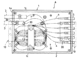
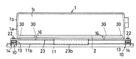
図6、図7に示すように、この光成端箱Aは、樹脂成形された筐体1の内部に、筐体底面と平行にベース板2が収容固定され、筐体1の一側面から挿入された光ケーブル3から多数本の分岐光ファイバ4が分岐されて、筐体1の対向する側面に装備された光接続アダプタ5に接続されるように構成されており、光ケーブル3と分岐光ファイバ4との間の分岐部位がベース板2の上下面において支持されるようになっている。
As shown in FIGS. 6 and 7, the optical termination box A includes a
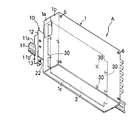
図8に示すように、筐体1は、ケース本体1a、これの前面に連結される前カバー1b、両者の間に挟持される一対の側板1cとで構成されており、前カバー1bの四隅に形成されたボス部1dに連結ネジ6が挿通されて、ケース本体1aの四隅に備えられたボス部1eに締め込み連結されるようになっている。このように筐体1は、ケース本体1aと側板1cとからなり前面が開放された筐体本体に、前カバー1bを取り外し可能に装着した構成を備える。
As shown in FIG. 8, the
側板1cは、ケース本体1aと前カバー1bの対向する端辺に溝嵌合されており、前カバー1bを取外すことで側板1cを抜き外すことが可能となっている。
The
ケース本体1aの底面4箇所にはボス部1fが突設されており、これらボス部1fに載置されたベース板2が筐体内方から装着した連結ネジ7によってケース本体1aの底面と平行に連結固定される。
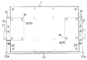
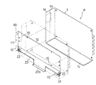
ケース本体1aの底面における4周辺近くには4個1組の連結孔8が形成されており、その対向する2組の連結孔8を用いて一対の取付け用金具10がケース本体1aの背面に連結されるようになっている。
A set of four
取付け用金具10は、現場(光成端箱装着環境)に配備固定された支持レール11に光成端箱Aを取り付ける際に利用されるものであって、矩形平板からなる支持ベース12、支持ベース12の背面に雄型連結具の一例である連結雄ネジ16によってネジ連結される金具本体13、金具本体13の内部に組みつけられる可動係合部材14、等によって構成されている。
The mounting
支持レール11は、マンションやオフィスビルなどの施設における配電室などの(光成端箱装着環境)に配備されて、主として横向きにネジ連結固定されるものであり、その幅方向の両端辺に一対の取付け用フランジ11a,11bを備えたもの(DINレールなど)が用いられる。
The
支持ベース12の四隅にはネジ孔15が形成されており、ケース本体1aに形成された1組の連結孔8に筐体内方から挿入された連結雄ネジ16を支持ベース12のネジ孔15に締め込むことで取付け用金具10を筐体背面(筐体底面外側)の所定位置に着脱可能に固定することができるようになっている。
Screw holes 15 are formed at the four corners of the
ベース板2は、切欠30を有している。切欠30は、連結雄ねじ16を筐体内側から連結孔8を挿通させて取り付け用金具10に連結させる作業を許容するものである。切欠30は、ベース板2が筐体1に装着された状態において各連結孔8の上方に位置する。また、切欠30は、連結雄ねじ16のねじ頭が挿通可能である大きさ(径)を備え、さらには光成端箱Aを装着環境に設置する作業者が、前面カバー1bを取り外した筐体内側から連結雄ねじ16を連結孔8に挿通させたうえでさらに連結雄ねじ16を取り付け用金具10に連結させる作業が容易となる大きさ(径)を備える。切欠30としては、ベース板2の端部を切欠いて形成した形状もよいし、ベース板2の中央部に貫通孔として形成した形状でもよい。
The
金具本体13は、金属板材を断面形状コの字形に屈曲して上下に長く形成されており、その開放側の端辺には、支持レール11の一方の取付け用フランジ11aに係止される固定係合部17が凹入形成されている。
The metal
可動係合部材14も金属板材を屈曲して形成されており、その長手方向中間部に形成した長孔18に、金具本体13に貫通装着した支持ピン19が挿通され、可動係合部材14が長孔18を介して上下に移動可能に支持されている。
The
可動係合部材14には、金具本体13から露出する係合爪部14aが形成されており、可動係合部材14を上方に移動させることで、係合爪部14aを支持レール11における下方の取付け用フランジ11bに係止させることができるようになっている。
The
金具本体13に可動係合部材14を上下移動可能に支持する支持ピン19にはねじりバネ20が外嵌装着され、このねじりバネ20の弾力によって可動係合部材の係合爪部14aが金具本体13から露出する方向に付勢されている。
A
金具本体13の下端部近くには図中上下に長い長孔21が形成され、この長孔21に挿通した固定用ネジ22が可動係合部材14の下端部近くにねじ込み連結されている。
A long elongated
取付け用金具10を筐体1に連結した状態において、支持ベース12の金具本体連結部位(固定用ネジ22およびその固定操作部)が筐体1の外方に突出されて、固定用ネジ22およびその固定操作部位を前方から目視操作することができるようになっている。なお、支持ベース12の金具本体連結部位(固定用ネジ22およびその固定操作部)が筐体1の外方に突出するとは、筐体1の裏面から金具本体連結部位が突出していることだけを意味するのではなく、筐体1や支持ベース12等を支持レール11のレール面に投影させた状態で金具本体連結部位が筐体1の側面の外方に位置することすべてを意味する。
In a state where the mounting
この例の光成端箱取付け構造は以上のようであり、支持レール11への取付け用金具10の装着手順を図9に基づいて説明する。
The optical termination box mounting structure of this example is as described above, and the mounting procedure of the mounting
この場合、取付け用金具10は、先にケース本体1aに連結して、その後、ケース本体1aに連結した取付け用金具10を支持レール11に装着操作する手順、あるいは、先に取付け用金具10を支持レール11に装着してから、支持レール11に装着した取付け用金具10にケース本体1aを連結操作する手順のいずれかを選択することができる。いずれの手順においても取付け用金具10をケース本体1aに連結する手順は、連結雄ねじ16を筐体内側から連結孔8を挿通させて取り付け用金具10に連結させることで実施される。その際、筐体内部にはベース板2が先に取付けられており、連結雄ねじ16を取り付け用金具10に連結させる作業において、ベース板2が邪魔になることが考えられるが、ベース板2には切欠30が形成されており、連結雄ねじ16を切欠30に挿通させることでベース板2が上記作業の邪魔になることはない。
In this case, the mounting
なお、筐体1の一側面から光ケーブル3を挿入させたうえで、光ケーブル3を筐体内で多数本の分岐光ファイバ4に分岐させ、さらに、多数本の分岐光ファイバ4を、筐体1の対向する側面に装備された光接続アダプタ5に接続する作業は、光成端箱Aを支持レール11に装着したのち実施される。
In addition, after inserting the optical cable 3 from one side of the
支持レール11へ取付け用金具10を装着するに際しては、図9(a)に示すように、取付け用金具10を支持レール11に前方から近づけ、図9(b)に示すように、先ず、取付け用金具10を斜め姿勢にして固定係合部17を上方の取付け用フランジ11aに上方から係止する。
When attaching the mounting
次に、図9(b)中の矢印で示すように、固定係合部17の係止箇所を中心にして取付け用金具10を支持レール側に揺動させる。この揺動によって可動係合部材14における係合爪部14aの傾斜外縁が下方の取付け用フランジ11bの端縁に押し付けられ、さらに強く揺動操作することで、その押し付け反力によって可動係合部材14が下方に押し動かされる。
Next, as shown by the arrow in FIG. 9B, the mounting
取付け用フランジ11bが係合爪部14aを乗越えたところで、図9(c)に示すように、可動係合部材14がねじりバネ20の弾力によって上方に移動して取付け用フランジ11bに係合爪部14aを係止させる。
When the mounting
その後、固定用ネジ22を締め込み操作して可動係合部材14の下部を上方に引き寄せることで、係合爪部14aを取付け用フランジ11bに強固に係止させるとともに、固定用ネジ22が金具本体13に固定される。これにより、可動係合部材14が上下に移動することが阻止される。さらにこれによって、取付け用金具10が支持レール11に対して長手方向にズレ動いたり、脱落することが阻止される。
Thereafter, the fixing
なお、固定用ネジ22を弛めて可動係合部材14を下方に移動操作して、上記手順を逆に行うことで取付け用金具10を支持レール11から取り外すことができる。また、図9における取付け用金具10の取付向き(図中の上下)は、あくまでも説明のために本明細書において仮に設定したものであって、実際の取付け用金具10の取付向きは、図9とは上下が逆になる等種々変化し、支持レール11の取付向きによっては水平の向きや斜めの向きになることもありえる。
The mounting
図11〜図16に、光成端箱取付け構造の第2の実施の形態が示されている。この例における光成端箱A、および、取付け用金具10の構成は第1の実施の形態と同様であるが、取付け用金具10の操作性を高めるために以下のような構成が付加されている。
11 to 16 show a second embodiment of an optical termination box mounting structure. The configuration of the optical termination box A and the mounting
すなわち、この例においては、一対の取付け用金具10における各可動係合部材14が固定用ネジ22を介して共通の操作部材23で連結されている。
That is, in this example, the movable engaging
操作部材23は、横長金属板材の両端部を上方に屈折して構成されており、両端の上方屈折部23aに形成したバカ孔24に固定用ネジ22が挿通されて、金具本体13の内部に配備された可動係合部材14にねじ込み連結されている。
The
この構成によると、左右一対の取付け用金具10における固定用ネジ22を弛めた状態で、筐体1の下側外方に露出している操作部材23を引き下げることで、左右の可動係合部材14を同時に下方に移動させて支持レール11の取付け用フランジ11bから離脱させることができ、支持レール11に対する取付け用金具10の脱着操作が容易なものとなる。
According to this configuration, the left and right movable engagements can be achieved by pulling down the
図17〜図22に、光成端箱取付け構造の第3の実施の形態が示されている。 17 to 22 show a third embodiment of the optical termination box mounting structure.
この例における光成端箱Aの構成、および、取付け用金具10の基本構成は第1の実施の形態と同様であるが、取付け用金具10に以下に示すような改造が施されている。
The configuration of the optical termination box A and the basic configuration of the mounting
すなわち、この例においては、一対の取付け用金具10の支持ベース12は筐体Aからはみ出る大きさの単一のもので共用されており、この支持ベース12の両端はみ出し部位にそれぞれ金具本体13が連結されている。
That is, in this example, the
また、第2の実施の形態と同様に、左右の金具本体13に亘って横長板材からなる操作部材23が固定用ネジ22を介して架設されて、各金具本体13に組み込まれた左右の可動係合部材14を同時に移動操作できるよう構成されている。操作部材23の中央部には操作部23bが筐体外方に突出するよう屈折延出されている。これにより、可動係合部材14の移動固定操作ならびに固定解除操作を筐体1の外側で実施することが可能となってその作業の容易化が図られている。
Similarly to the second embodiment, an
図23に、第3の実施の形態の変形例が示されている。 FIG. 23 shows a modification of the third embodiment.
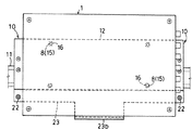
この例において、一対の取付け用金具10に共用される支持ベース12の中央部位に連結孔25が形成され、ケース本体1aの底面中央部位に形成した中央連結孔26に挿通される中央連結ネジ27が連結孔25に連結されるようになっている。これによると、中央連結ネジ27を支点として回動することで、筐体1を横長姿勢あるいは縦長姿勢に切換え選択して連結することが可能である。
In this example, a connecting
図24〜図29に、光成端箱取付け構造の第4の実施の形態が示されている。 24 to 29 show a fourth embodiment of an optical termination box mounting structure.
この実施の形態における光成端箱Aの構成、および、取付け用金具10の基本構成は第1の実施の形態と同様であるが、取付け用金具10に以下に示すような改造が施されている。
The configuration of the optical termination box A and the basic configuration of the mounting
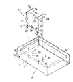
すなわち、この実施の形態においては、一対の取付け用金具10の支持ベース12の一端辺から一対の連結片12aが直角に屈折延出されるとともに、支持ベース12の四周辺には金具本体13をネジ連結する連結孔28がそれぞれ形成されている。
That is, in this embodiment, the pair of connecting
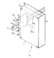
この構成によると、図24〜図26に示すように、支持ベース12の上端に連結片12aが位置し、金具本体13が左右端に位置するように金具本体13を連結することで、ケース本体1aを上向きにした水平姿勢で光成端箱Aを支持することができ、また、図27〜図29に示すように、支持ベース12の左右端に連結片12aが位置し、金具本体13が左右端に位置するように金具本体13を連結することで、ケース本体1aを横向きにした起立姿勢で光成端箱Aを支持することができる。
According to this configuration, as shown in FIGS. 24 to 26, the case main body is connected by connecting the metal
本発明は、以下のような形態で実施することもできる。 The present invention can also be implemented in the following forms.
(1)上述の実施形態では、ベース板2を筐体1に装着した状態で連結雄ネジ16を筐体内方から締付け操作して取付け用金具10を装着することになるが、ベース板2を筐体1に取り外した状態で、連結雄ネジ16を筐体内方から締付け操作して取付け用金具10を筐体外面に装着したうえで、ベース板2を筐体1に装着することができる。
(1) In the above-described embodiment, the mounting
(2)筐体1は、前カバー1bを備えない開放型のものであってもよい。
(2) The
1 筐体
2 ベース板
3 光ケーブル
4 分岐光ファイバ
8 連結孔
10 取付け用金具
11 支持レール
11a 取付け用フランジ
11b 取付け用フランジ
14 可動係合部材
16 連結雄ネジ
17 固定係合部
22 操作部材
30 切欠
DESCRIPTION OF
Claims (9)
前面が開放されたあるいは前面が開放可能な筐体と、
前記光ケーブルと前記分岐光ファイバとの間の分岐部位を支持するために、筐体底面と平行に前記筐体に収納されるベース板と、
光成端箱装着環境に配備される支持レールに当該光成端箱を取付ける取付け用金具を前記筐体の底面外側に着脱可能に取り付ける雄型連結具を挿通させるために前記筐体の底面に形成された連結孔と、
前記雄型連結具を筐体内側から前記連結孔を挿通させて前記取り付け用金具に連結させる作業を許容するために、前記ベース板に形成された切欠と、
を備える、
ことを特徴とする光成端箱。 An optical termination box for branching a branched optical fiber from an optical cable,
A case where the front is open or the front is openable,
A base plate housed in the housing parallel to the bottom of the housing in order to support a branching portion between the optical cable and the branch optical fiber;
In order to insert a male connector for removably attaching a mounting bracket for attaching the optical termination box to a support rail provided in an optical termination box mounting environment, on the bottom surface of the casing. A formed connection hole;
In order to allow the male connector to be connected to the mounting bracket by inserting the connection hole from the inside of the housing, a notch formed in the base plate,
Comprising
An optical termination box characterized by that.
前面が開放されたあるいは前面が開放可能な筐体と、
前記光ケーブルと前記分岐光ファイバとの間の分岐部位を支持するために、筐体底面と平行に前記筐体に収納されるベース板と、
光成端箱装着環境に配備される支持レールに当該光成端箱を取付ける取付け用金具と、
前記取付け用金具を、前記筐体の底面外側に着脱可能に取り付ける雄型連結具と、
前記筐体の底面に形成された前記雄型連結具用の連結孔と、
前記雄型連結具を筐体内側から前記連結孔を挿通させて前記取り付け用金具に連結させる作業を許容するために、前記ベース板に形成された切欠と、
を備える、
ことを特徴とする光成端箱。 An optical termination box for branching a branched optical fiber from an optical cable,
A case where the front is open or the front is openable,
A base plate housed in the housing parallel to the bottom of the housing in order to support a branching portion between the optical cable and the branched optical fiber;
Mounting brackets for attaching the optical termination box to the support rail deployed in the optical termination box installation environment;
A male connector for removably attaching the mounting bracket to the outside of the bottom surface of the housing;
A connection hole for the male connector formed on the bottom surface of the housing;
In order to allow the male connector to be connected to the mounting bracket by inserting the connection hole from the inside of the housing, a notch formed in the base plate,
Comprising
An optical termination box characterized by that.
ことを特徴とする請求項1または2記載の光成端箱。 A plurality of sets of the connection holes for attaching the mounting brackets in a plurality of different postures are formed on the bottom surface of the housing, and a plurality of the notches corresponding to the connection holes are formed in the base plate.
The optical termination box according to claim 1 or 2, wherein
ことを特徴とする請求項1または2記載の光成端箱。 The opposing side plates in the housing are configured to be removable.
The optical termination box according to claim 1 or 2, wherein
ことを特徴とする請求項1または2記載の光成端箱。 The mounting bracket includes a fixed engagement portion that is locked to one of the mounting flanges formed at both ends in the width direction of the support rail, and a movable engagement member that is engaged with and disengaged from the other mounting flange. Having
The optical termination box according to claim 1 or 2, wherein
ことを特徴とする請求項5記載の光成端箱。 The movable engagement member is configured to be able to be fixed to the engagement operation position.
The optical termination box according to claim 5.
ことを特徴とする請求項5または6記載の光成端箱。 The fixed operation portion of the movable engagement member is arranged to protrude outward from the housing.
The optical termination box according to claim 5 or 6, wherein
ことを特徴とする請求項6または7記載の光成端箱。 A plurality of mounting brackets corresponding to a plurality of locations in the longitudinal direction of the support rail are attached to the housing, and each movable engagement member is connected by an operation member so as to be integrally movable.
8. The optical termination box according to claim 6 or 7, wherein:
ことを特徴とする請求項8記載の光成端箱。 The plurality of mounting brackets are connected to a single support base, and the housing is connected to the support base so as to be rotatable around a fulcrum.
The optical termination box according to claim 8.
Priority Applications (1)
| Application Number | Priority Date | Filing Date | Title |
|---|---|---|---|
| JP2008220923A JP5289866B2 (en) | 2008-08-29 | 2008-08-29 | Optical termination box |
Applications Claiming Priority (1)
| Application Number | Priority Date | Filing Date | Title |
|---|---|---|---|
| JP2008220923A JP5289866B2 (en) | 2008-08-29 | 2008-08-29 | Optical termination box |
Publications (2)
| Publication Number | Publication Date |
|---|---|
| JP2010054894A true JP2010054894A (en) | 2010-03-11 |
| JP5289866B2 JP5289866B2 (en) | 2013-09-11 |
Family
ID=42070876
Family Applications (1)
| Application Number | Title | Priority Date | Filing Date |
|---|---|---|---|
| JP2008220923A Expired - Fee Related JP5289866B2 (en) | 2008-08-29 | 2008-08-29 | Optical termination box |
Country Status (1)
| Country | Link |
|---|---|
| JP (1) | JP5289866B2 (en) |
Cited By (3)
| Publication number | Priority date | Publication date | Assignee | Title |
|---|---|---|---|---|
| JP2020134742A (en) * | 2019-02-21 | 2020-08-31 | 株式会社昭電 | Optical termination box |
| KR20200113158A (en) * | 2019-03-20 | 2020-10-06 | 썬그로우 파워 서플라이 컴퍼니 리미티드 | Case bracket and electric equipment |
| KR102185333B1 (en) * | 2020-06-30 | 2020-12-02 | 최장헌 | Fixing structure for box using hinge member |
Citations (4)
| Publication number | Priority date | Publication date | Assignee | Title |
|---|---|---|---|---|
| JPH0428601U (en) * | 1990-07-04 | 1992-03-06 | ||
| JP2003258452A (en) * | 2002-02-27 | 2003-09-12 | Omron Corp | Device fitting structure |
| JP2004319600A (en) * | 2003-04-11 | 2004-11-11 | Densei Lambda Kk | Electric equipment attaching structure |
| JP2005064114A (en) * | 2003-08-08 | 2005-03-10 | Omron Corp | Structure for mounting din rail |
-
2008
- 2008-08-29 JP JP2008220923A patent/JP5289866B2/en not_active Expired - Fee Related
Patent Citations (4)
| Publication number | Priority date | Publication date | Assignee | Title |
|---|---|---|---|---|
| JPH0428601U (en) * | 1990-07-04 | 1992-03-06 | ||
| JP2003258452A (en) * | 2002-02-27 | 2003-09-12 | Omron Corp | Device fitting structure |
| JP2004319600A (en) * | 2003-04-11 | 2004-11-11 | Densei Lambda Kk | Electric equipment attaching structure |
| JP2005064114A (en) * | 2003-08-08 | 2005-03-10 | Omron Corp | Structure for mounting din rail |
Cited By (5)
| Publication number | Priority date | Publication date | Assignee | Title |
|---|---|---|---|---|
| JP2020134742A (en) * | 2019-02-21 | 2020-08-31 | 株式会社昭電 | Optical termination box |
| JP7281295B2 (en) | 2019-02-21 | 2023-05-25 | 株式会社昭電 | optical termination box |
| KR20200113158A (en) * | 2019-03-20 | 2020-10-06 | 썬그로우 파워 서플라이 컴퍼니 리미티드 | Case bracket and electric equipment |
| KR102533053B1 (en) * | 2019-03-20 | 2023-05-16 | 썬그로우 파워 서플라이 컴퍼니 리미티드 | Case bracket and electric equipment |
| KR102185333B1 (en) * | 2020-06-30 | 2020-12-02 | 최장헌 | Fixing structure for box using hinge member |
Also Published As
| Publication number | Publication date |
|---|---|
| JP5289866B2 (en) | 2013-09-11 |
Similar Documents
| Publication | Publication Date | Title |
|---|---|---|
| MX2011004760A (en) | Field terminated fiber patch panel for rack and wall mounting. | |
| JP5289866B2 (en) | Optical termination box | |
| JP2014078425A (en) | Lighting fixture | |
| JP2017103006A (en) | Luminaire | |
| JP2012074213A (en) | Lighting fixture | |
| JP2017157188A (en) | Box body for information distribution board | |
| JP4958816B2 (en) | Toolless blank panel | |
| KR100732726B1 (en) | The floor distributing wires box | |
| JP6478389B2 (en) | Display support fixture | |
| US6783298B2 (en) | Device for connecting a control mechanism to an end of a support arm system | |
| JP2017195167A (en) | Lighting fixture | |
| JP6541062B2 (en) | lighting equipment | |
| JP5147118B2 (en) | lighting equipment | |
| JP6622111B2 (en) | Box for information distribution board | |
| WO2012120685A1 (en) | Connector retaining structure | |
| JP2004037596A (en) | Mounting plate for material shelf with same, and tray for optical connection having same | |
| JP5078083B2 (en) | Adapter mounting structure | |
| JP5270626B2 (en) | Equipment wall mounting structure | |
| JP2007114314A (en) | Optical plug socket | |
| JP3168237U (en) | Electrical equipment | |
| JP2018022556A (en) | Hanging lighting fixture, coupling tool and lighting system | |
| JP2009258244A (en) | Splice unit | |
| JP6668107B2 (en) | Box for information distribution board | |
| JP4232540B2 (en) | Free plan compatible wiring system | |
| JP2003309921A (en) | Floor wiring device |
Legal Events
| Date | Code | Title | Description |
|---|---|---|---|
| A621 | Written request for application examination |
Free format text: JAPANESE INTERMEDIATE CODE: A621 Effective date: 20110728 |
|
| A977 | Report on retrieval |
Free format text: JAPANESE INTERMEDIATE CODE: A971007 Effective date: 20120518 |
|
| TRDD | Decision of grant or rejection written | ||
| A01 | Written decision to grant a patent or to grant a registration (utility model) |
Free format text: JAPANESE INTERMEDIATE CODE: A01 Effective date: 20130514 |
|
| A61 | First payment of annual fees (during grant procedure) |
Free format text: JAPANESE INTERMEDIATE CODE: A61 Effective date: 20130605 |
|
| R150 | Certificate of patent or registration of utility model |
Ref document number: 5289866 Country of ref document: JP Free format text: JAPANESE INTERMEDIATE CODE: R150 |
|
| LAPS | Cancellation because of no payment of annual fees |