JP2010054442A - Battery system - Google Patents
Battery system Download PDFInfo
- Publication number
- JP2010054442A JP2010054442A JP2008221929A JP2008221929A JP2010054442A JP 2010054442 A JP2010054442 A JP 2010054442A JP 2008221929 A JP2008221929 A JP 2008221929A JP 2008221929 A JP2008221929 A JP 2008221929A JP 2010054442 A JP2010054442 A JP 2010054442A
- Authority
- JP
- Japan
- Prior art keywords
- voltage
- battery
- voltage detection
- detection circuit
- cell
- Prior art date
- Legal status (The legal status is an assumption and is not a legal conclusion. Google has not performed a legal analysis and makes no representation as to the accuracy of the status listed.)
- Granted
Links
Images

Classifications
-
- Y—GENERAL TAGGING OF NEW TECHNOLOGICAL DEVELOPMENTS; GENERAL TAGGING OF CROSS-SECTIONAL TECHNOLOGIES SPANNING OVER SEVERAL SECTIONS OF THE IPC; TECHNICAL SUBJECTS COVERED BY FORMER USPC CROSS-REFERENCE ART COLLECTIONS [XRACs] AND DIGESTS
- Y02—TECHNOLOGIES OR APPLICATIONS FOR MITIGATION OR ADAPTATION AGAINST CLIMATE CHANGE
- Y02E—REDUCTION OF GREENHOUSE GAS [GHG] EMISSIONS, RELATED TO ENERGY GENERATION, TRANSMISSION OR DISTRIBUTION
- Y02E60/00—Enabling technologies; Technologies with a potential or indirect contribution to GHG emissions mitigation
- Y02E60/10—Energy storage using batteries
Landscapes
- Tests Of Electric Status Of Batteries (AREA)
- Secondary Cells (AREA)
Abstract
Description
本発明は、1以上の単セルからなる組電池を使用した電池システムに係り、特に各電池電圧を検出する高耐圧特性の電圧検出回路を備えた電池システムに関する。 The present invention relates to a battery system using an assembled battery made up of one or more single cells, and more particularly to a battery system including a voltage detection circuit having a high withstand voltage characteristic for detecting each battery voltage.
近年、高電圧での充放電を可能とすべく蓄電池を有する単セルが多数直列に接続された組電池が製造されている。この組電池は、パーソナルコンピュータ等の移動体に内蔵する電源や、電気自動車、燃料電池自動車やハイブリッドカーの動力源又は補助動力源である電動モータに使用されている。 In recent years, assembled batteries in which a large number of single cells each having a storage battery are connected in series to enable charging and discharging at a high voltage have been manufactured. This assembled battery is used for a power source built in a moving body such as a personal computer, and an electric motor which is a power source or an auxiliary power source of an electric vehicle, a fuel cell vehicle and a hybrid car.
この組電池に使用する電池には高電圧及び高出力を実現するために、特に、リチウムイオン電池が用いられるが、当該電池は、キャパシタ等と比較して格段に大きなエネルギーを蓄えることができるので、電池自体及び電池の周辺回路の安全性を十分に確保する必要がある。 In order to realize a high voltage and a high output, a lithium ion battery is particularly used for the battery used in this assembled battery, but the battery can store much larger energy than a capacitor or the like. In addition, it is necessary to sufficiently secure the safety of the battery itself and the peripheral circuits of the battery.
ここで、電池の安全性を確保するために、各セル、あるいは組電池全体の電圧を監視することで過充電及び過放電を防止する電池システムの開発が行われている。特に、リチウムイオン電池を採用する場合では、過充電や過放電が生じることにより電池間の接続線等が断線し、電池の発火や発煙までに至るケースも想定されるため、組電池内の直列に接続した各セルの電圧を検出することによりセル単位で異常電圧の抑制を図っている。 Here, in order to ensure the safety of the battery, a battery system that prevents overcharge and overdischarge by monitoring the voltage of each cell or the entire assembled battery has been developed. In particular, when a lithium ion battery is used, it is assumed that overcharge and overdischarge cause disconnection of the connection lines between the batteries, leading to ignition and smoke of the battery. By detecting the voltage of each cell connected to the cell, an abnormal voltage is suppressed on a cell-by-cell basis.
そのため、組電池を構成するセル毎の電圧を検出する電子回路が必要であり、具体的には、コンデンサ、スイッチやオペアンプ等で構成された電圧検出回路が利用され、さらに、マイクロコンピュータにより充放電を監視することも多く、この場合の電圧検出回路にはアナログ−デジタル変換器も使用される。また、複数セルの電圧を検出するにあたり多くの電気回路素子が必要となるので、回路の小型化、信頼性向上、低コスト化等の要望を加味し、このような電圧検出回路を搭載した集積回路も開発されている。 Therefore, an electronic circuit that detects the voltage of each cell constituting the assembled battery is required. Specifically, a voltage detection circuit including a capacitor, a switch, an operational amplifier, and the like is used, and charging and discharging are performed by a microcomputer. In this case, an analog-digital converter is also used for the voltage detection circuit. In addition, since many electric circuit elements are required to detect the voltage of a plurality of cells, an integrated circuit equipped with such a voltage detection circuit is added in consideration of demands such as circuit miniaturization, reliability improvement, and cost reduction. Circuits are also being developed.
なお、従来技術として、例えば、直列接続された複数の単電池からなるモジュールを監視する電池用保護ICが提案されており(特許文献1参照)、電池の充電時において、モジュール内のいずれかの電池の端子電圧が所定値以上になった場合に、過充電状態と判定し過電圧信号を出力する過電圧検出回路と、放電時において、モジュール内のいずれかの電池の端子電圧が所定値以下になった場合に、過放電状態と判定し過放電信号を出力する過放電検出回路と、が配設されている。さらに、この電池保護ICは、過電圧信号を検出した際にオンすることにより通報可能な第1スイッチと、過放電信号を検出した際にオンすることにより通報可能な第2スイッチとを備えている。
ところで、上記のような過充電及び放電を防止する電池システムによれば、各セルには端子電圧が電圧検出回路の許容電圧範囲内に収まる電池が使用され、この許容電圧範囲内でしか電圧の変動は許されない。このことから、電圧検出回路における電圧を検出する範囲は、下限は0Vから上限は電池の上限電圧を数V程度上回るものとし、例えば、リチウムイオン電池では単セル当たり2.8V〜4.5V程度の値が上限電圧であるため、この検出範囲が約3.5V〜5V程度となる。 By the way, according to the battery system for preventing overcharge and discharge as described above, a battery in which the terminal voltage is within the allowable voltage range of the voltage detection circuit is used for each cell, and the voltage of only within the allowable voltage range is used. Variation is not allowed. Thus, the voltage detection range in the voltage detection circuit is such that the lower limit is 0 V and the upper limit exceeds the upper limit voltage of the battery by several volts. For example, in the case of a lithium ion battery, about 2.8 V to 4.5 V per single cell. Since this value is the upper limit voltage, this detection range is about 3.5V to 5V.
しかしながら、例えば、このような電池をパーソナルコンピュータ等の移動体に搭載する場合において、振動などが生じることにより、当該移動体からの落下や他の部品と擦動することも想定され、電池間の接続線や電池電圧を検出するICとの検出線の断線により過電流が流れることで短絡状態が生じる可能性がある。 However, for example, when such a battery is mounted on a mobile object such as a personal computer, it is assumed that the battery may drop from the mobile object or rub against other parts due to vibrations. There is a possibility that a short circuit may occur due to an overcurrent flowing due to disconnection of the detection line with the connection line or the IC that detects battery voltage.
また、自動車等の車両に電動モータの動力源として搭載する場合には、振動が継続する走行状態で長期間に亘り使用されるので、配線の断裂や部品の擦動により、部品のズレや回路の短絡が生じる可能性がある。これにより、電圧検出回路に異常な電圧や電流が流れることで、回路部品等が発火や発煙したり、自動車の運転に際し著しく支障が生じる場合がある。 In addition, when it is mounted on a vehicle such as an automobile as a power source for an electric motor, it is used for a long period of time in a driving state where vibrations continue. May cause a short circuit. As a result, an abnormal voltage or current flows through the voltage detection circuit, which may cause circuit components to ignite or smoke, or cause a significant hindrance in driving the automobile.
特に、セル間の接続が断線した場合には、電圧検出回路の耐圧を超える異常電圧がこの電圧検出回路に加わってしまい、検出回路の短絡が生じる他、回路部品や回路基板が発熱、発煙する。また、場合によっては発火する可能性もある。 In particular, when the connection between cells is disconnected, an abnormal voltage exceeding the withstand voltage of the voltage detection circuit is applied to the voltage detection circuit, resulting in a short circuit of the detection circuit, and circuit components and circuit boards generating heat and smoke. . In some cases, it may catch fire.
例えば、図2のように、3個のセルを直列に接続し、各セルの電池1a〜1cの電圧を検出する電圧検出回路を有する電池保護IC2´を備えた電池システムにおいて、セル間の接続が断線した場合を説明する。 For example, as shown in FIG. 2, in a battery system including a battery protection IC 2 ′ having a voltage detection circuit that connects three cells in series and detects the voltages of the batteries 1 a to 1 c of each cell, connection between cells The case where is disconnected will be described.
この電池保護IC2´は、高電位側の電池1cと低電位側の電池1aに接続された電源線5b、aを通じて電気供給を受けることで動作し、内蔵される電圧検出回路により、各セルの電池1a〜1cの電圧を計測線3b〜3dを通じてそれぞれ検出する。なお、電池保護IC2´は、また、電圧検出回路により各電池セルの電圧を監視することで、電池の過充電及び放電状態を検知し、その電圧情報を制御部6に送信する機能を有している。
This battery protection IC 2 'operates by receiving electric supply through
ここで、図2の通り、計測線3bが断線した場合には、一般的に、隣接する計測線3aに接触する可能性が高く、断線した計測線3bが計測線3aに接触すると、計測線3bを通じて検出されていた電圧Vd1は0Vとなる。また、一端が電池1bと電池1c間に接続され、他端が電池保護IC2´に接続された計測線3cを通じて検出される電圧Vd2は、電池1bと電池1cの合計電圧となる。
Here, as shown in FIG. 2, when the
すなわち、各セルの電池1a〜1cに同電圧の電池を使用している場合には、計測線3cを通じて電圧Vd2を検出する電圧検出回路には、各セルの電池電圧の2倍の電圧が加わることになる。例えば、高充電状態にあった電池1a〜1cの各電圧が5Vの場合に、計測線3bが断線することで上記のような事象が生じると、計測線3cを通じて検出される電圧Vd2は10Vとなる。
That is, when batteries of the same voltage are used for the batteries 1a to 1c of each cell, a voltage that is twice the battery voltage of each cell is applied to the voltage detection circuit that detects the voltage Vd2 through the
そのため、電池保護IC2´の各セルの電池1a〜1cの電圧を検出する電圧検出回路において、電圧計測入力に対する耐圧が各セルにかかる最大電圧の2倍以下である場合には、この電圧検出回路に過剰の電圧が加わることになり、電圧破壊を引き起こす。これにより、電池保護IC2´が破壊され、当該電池保護IC2´の発火、破裂や計測線の焼損等を引き起こし、さらには、電池システム全体も発熱し得る。また、発火等により高エネルギーを保持する電池の短絡も生じる。 Therefore, in the voltage detection circuit that detects the voltage of the batteries 1a to 1c of each cell of the battery protection IC 2 ′, when the withstand voltage against the voltage measurement input is less than twice the maximum voltage applied to each cell, this voltage detection circuit An excessive voltage will be applied to this, causing voltage breakdown. As a result, the battery protection IC 2 ′ is destroyed, and the battery protection IC 2 ′ is ignited, ruptured, or the measurement line is burned, and the entire battery system can also generate heat. In addition, a short circuit of the battery that retains high energy occurs due to ignition or the like.
なお、上述した通り、各電池1a〜1cの電圧を検出する電圧検出回路の電圧検出範囲は、電池セルの通常の電圧変動範囲に基づいて設計するものであり、この電圧検出範囲を広くすることで、電圧検出回路に加わる過電圧に対応することも可能であるが、広すぎる電圧検出範囲は、電圧の検出精度を著しく低下させてしまう。 As described above, the voltage detection range of the voltage detection circuit that detects the voltages of the batteries 1a to 1c is designed based on the normal voltage fluctuation range of the battery cell, and this voltage detection range should be widened. Thus, it is possible to cope with an overvoltage applied to the voltage detection circuit, but a voltage detection range that is too wide will significantly reduce the voltage detection accuracy.
本発明は、上記の課題を解消するために提案されたものであって、その目的は、セル間の接続が断線した場合に、電圧検出回路の耐圧を当該回路に過渡的に加わる電圧以上にすることで、安全性を確保可能な電池システムを提供することにある。 The present invention has been proposed in order to solve the above-mentioned problems, and its purpose is to make the voltage detection circuit withstand voltage higher than the voltage transiently applied to the circuit when the connection between the cells is disconnected. This is to provide a battery system capable of ensuring safety.
上述した目的を達成するために、本発明は、モジュール内に直列に接続された複数の電池と前記各電池の電圧を検出する電圧検出回路を備えた電池システムにおいて、前記電圧検出回路は、前記各電池の電圧の3倍以上の耐圧を有することを特徴とする。 In order to achieve the above-described object, the present invention provides a battery system including a plurality of batteries connected in series in a module and a voltage detection circuit for detecting a voltage of each battery, wherein the voltage detection circuit includes It has a withstand voltage that is at least three times the voltage of each battery.
以上のような態様では、電池に繋がれた計測線のいずれかが断線し、断線した計測線の一端が他の計測線に接続され、電圧検出回路に両計測線を通っていた電圧、すなわち、各電池電圧の2倍の電圧が加わった場合であっても、電圧検出回路は、各電池の電圧の3倍の耐圧を有することから、電池システムの破損を防止することができる。すなわち、各セル電池電圧の2倍の過電圧が加わろうとも電圧検出回路の耐圧内であり、当該電圧検出回路を構成するディスクリート素子やICが破壊することはない。 In the above aspect, one of the measurement lines connected to the battery is disconnected, one end of the disconnected measurement line is connected to the other measurement line, and the voltage that has passed through both measurement lines to the voltage detection circuit, that is, Even when a voltage twice as large as each battery voltage is applied, the voltage detection circuit has a withstand voltage that is three times the voltage of each battery, so that the battery system can be prevented from being damaged. That is, even if an overvoltage twice as high as each cell battery voltage is applied, it is within the withstand voltage of the voltage detection circuit, and the discrete elements and ICs constituting the voltage detection circuit are not destroyed.
また、電圧検出回路が高耐圧であるため、数百Vの高電圧が要求され、多数の電池が必要となるハイブリッドカーや電気自動車に搭載する場合であっても安全性を確保でき、製品の信頼性の向上にも繋がる。 In addition, since the voltage detection circuit has a high withstand voltage, a high voltage of several hundred volts is required, and safety can be ensured even when it is installed in a hybrid car or electric vehicle that requires a large number of batteries. It also leads to improved reliability.
本発明は、前記電圧検出回路が、高耐圧用のコンデンサを有することを特徴とする点も一態様とする。 Another aspect of the present invention is that the voltage detection circuit includes a high-voltage capacitor.
このような態様では、高耐圧を実現するために、電圧検出回路を構成する素子自体を高耐圧用にするだけでなく、高耐圧用のコンデンサを採用することで、各電池の電圧の3倍以上の耐圧を実現している。これにより、上述したように、突如過電圧が加わろうとも電圧検出回路の耐圧内であるとして当該電圧検出回路の破損等を防止することが可能となる。 In such an embodiment, in order to realize a high breakdown voltage, not only the elements constituting the voltage detection circuit itself are used for a high breakdown voltage, but also by adopting a high breakdown voltage capacitor, the voltage of each battery is tripled. The above breakdown voltage is realized. As a result, as described above, it is possible to prevent damage to the voltage detection circuit, assuming that the voltage detection circuit is within the withstand voltage even if an overvoltage is suddenly applied.
以上のような本発明によれば、電池に繋がれた計測線のいずれかが断線し、断線した計測線の一端が他の計測線に接続され、電圧検出回路に両計測線を通っていた電圧、すなわち、各電池電圧の2倍の電圧が加わった場合であっても、電圧検出回路は、各電池の電圧の3倍の耐圧を有することから、当該回路の破損を防止可能な電池システムを提供することができる。つまり、各セル電池電圧の2倍の過電圧が加わろうとも電圧検出回路の耐圧内であり、当該電圧検出回路を構成するディスクリート素子やICは破壊されることはなく、短絡電流が流れることで生じる回路部品、IC及び回路パターン等の発熱、発煙、発火を抑制することが可能となる。 According to the present invention as described above, one of the measurement lines connected to the battery is disconnected, one end of the disconnected measurement line is connected to the other measurement line, and both measurement lines are passed through the voltage detection circuit. Even when a voltage, that is, twice the voltage of each battery voltage is applied, the voltage detection circuit has a withstand voltage that is three times the voltage of each battery, so that the battery system can prevent the circuit from being damaged. Can be provided. That is, even if an overvoltage twice as high as each cell battery voltage is applied, it is within the withstand voltage of the voltage detection circuit, and the discrete elements and ICs constituting the voltage detection circuit are not destroyed and are caused by the short circuit current flowing. Heat generation, smoke generation, and ignition of circuit components, ICs, and circuit patterns can be suppressed.
また、電圧検出回路が高耐圧であるため、数百Vの高電圧が要求され、多数の電池が必要となるハイブリッドカーや電気自動車に搭載する場合であっても安全性を確保でき、製品の信頼性を向上させることができる。 In addition, since the voltage detection circuit has a high withstand voltage, a high voltage of several hundred volts is required, and safety can be ensured even when it is installed in a hybrid car or electric vehicle that requires a large number of batteries. Reliability can be improved.
[本実施形態]
次に、本実施形態に係る電池システムを図1を参照して説明する。なお、下記で示す電池の数、セルの数、セル電圧は任意であるものとし、図1のような形態に限定するものではない。また、図2に示す構成と同様のものについては説明を省略し、同じ符号を付している。
[This embodiment]
Next, the battery system according to the present embodiment will be described with reference to FIG. It should be noted that the number of batteries, the number of cells, and the cell voltage shown below are arbitrary and are not limited to the form shown in FIG. The description of the same configuration as that shown in FIG. 2 is omitted, and the same reference numerals are given.
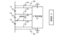
図1では、電池1a〜1cを各々有する3個のセルが直列に接続されたモジュールが配設されており、各セルの電圧が3.6Vであるリチウム電池を使用したケースを例にとる。図示しないが、実際には1以上のモジュールが直列に接続されている。 In FIG. 1, a module in which three cells each having batteries 1a to 1c are connected in series is provided, and a lithium battery in which the voltage of each cell is 3.6V is used as an example. Although not shown, one or more modules are actually connected in series.
本実施形態では、後述するが、セル電池の電圧を検出する電池電圧検出部2(電圧検出回路に対応する。)の耐圧を各電池セルの電圧の検出範囲に対して3倍以上とする点に特徴を有している。 In this embodiment, as will be described later, the withstand voltage of the battery voltage detection unit 2 (corresponding to a voltage detection circuit) that detects the voltage of the cell battery is set to be three times or more the voltage detection range of each battery cell. It has the characteristics.
図1の通り、3個のセルが直列に接続されたモジュール内には、各セルの電圧を測定する電池電圧検出部2(電圧検出回路に対応する。)が設けられ、各セルに対応する電池1a〜1cが当該電池電圧検出部2にセル電圧の計測線3a〜3dを介して接続されている。この電池電圧検出部2は、ディスクリート素子で構成した回路とIC化した回路から構成されている。
As shown in FIG. 1, a battery voltage detector 2 (corresponding to a voltage detection circuit) that measures the voltage of each cell is provided in a module in which three cells are connected in series, and corresponds to each cell. The batteries 1a to 1c are connected to the battery voltage detection unit 2 via cell
この電池電圧検出部2には、高耐圧の当該電池電圧検出部2を構成するために一例として高耐圧コンデンサ4a〜4cが配設されている。この高耐圧コンデンサ4a〜4cにより電池電圧検出部2は、過電圧が付加されていても耐圧内となる。
The battery voltage detection unit 2 is provided with
特に、本実施形態では、各セルの電池電圧の3倍以上の高耐圧コンデンサ4a〜4cを使用する。図1によれば、各電池電圧は、3.6Vであるため、この高耐圧コンデンサ4a〜4cには、耐圧が10.8V以上のものを採用している。
In particular, in the present embodiment,
また、電池電圧検出部2の両端には、モジュール内の電池セル1aの低電位側と電池セル1cの高電位側に各々繋がる電源線5a、5bが接続され、さらに、電源VDDと接地GNDにも接続されている。
Further,
そして、この電池電圧検出部2により検出された電池電圧が制御部6に送信され、当該制御部6でこの送られてきた電圧値によりセル間の断線を判断する。つまり、この制御部6においてセル間の断線を検知すれば、電池1a〜1cへの充放電を停止するよう制御可能である。また、制御部6では、断線状態を検知せずとも、電池電圧検出部2を通じて検出された電圧に基づいて電池1a〜1cへの充放電を制御する。
Then, the battery voltage detected by the battery voltage detection unit 2 is transmitted to the
以上のような構成を有する電池システムによれば、セル電圧の計測線3a〜3dのいずれかが断線し、断線した計測線の一端が他の計測線に接続され、電池電圧検出部2に両計測線を通っていた電池電圧、すなわち、各電池セルの電圧の2倍の電圧が加わろうとも、電池電圧検出部2に各セルの電池電圧の3倍の耐圧を有する高耐圧コンデンサ4a〜4cを備えているので、当該電池システムの過電圧による破損を防止することができる。すなわち、各セルの電池電圧の2倍の過電圧が加わろうとも電池電圧検出部2の耐圧内であり、当該電池電圧検出部2内のICが破壊することはない。
According to the battery system having the above-described configuration, one of the cell
また、電池電圧検出部2を高耐圧とすることにより、数百Vの高電圧が要求され、多数の電池が必要となるハイブリッドカーや電気自動車に搭載する場合であっても安全性を確保でき、製品の信頼性の向上にも繋がる。 In addition, by making the battery voltage detector 2 have a high withstand voltage, a high voltage of several hundred volts is required, and safety can be ensured even when the battery voltage detector 2 is installed in a hybrid car or electric vehicle that requires a large number of batteries. This also leads to improved product reliability.
[他の実施形態]
なお、本発明は、上記のような高耐圧のコンデンサ4a〜4cを電池電圧検出部2に配設することにより当該電池電圧検出部2の耐圧を高める実施形態に限定するものではなく、この電池電圧検出部2を構成する回路自体に高耐圧の素子を採用し、当該検出部2の耐圧を向上させる実施形態も包含する。つまり、本発明における電池電圧検出部2は、各電池電圧の3倍以上の耐圧を実現可能であれば、如何様に構成された電圧検出回路であっても構わない。
[Other Embodiments]
In addition, this invention is not limited to embodiment which raises the pressure | voltage resistance of the said battery voltage detection part 2 by arrange | positioning the above high voltage | pressure-
1a〜1c…電池
2…電池電圧検出部
2´…電池保護IC
3a〜3c…計測線
4a〜4c…高耐圧コンデンサ
5a、b…電源線
6…制御部
1a to 1c ... battery 2 ... battery voltage detector 2 '... battery protection IC
3a to 3c ...
Claims (3)
前記電圧検出回路は、前記各電池の電圧の3倍以上の耐圧を有することを特徴とする電池システム。 In a battery system comprising a plurality of batteries connected in series in a module and a voltage detection circuit for detecting the voltage of each battery,
The battery system, wherein the voltage detection circuit has a withstand voltage that is at least three times the voltage of each battery.
Priority Applications (1)
| Application Number | Priority Date | Filing Date | Title |
|---|---|---|---|
| JP2008221929A JP5284009B2 (en) | 2008-08-29 | 2008-08-29 | Battery system |
Applications Claiming Priority (1)
| Application Number | Priority Date | Filing Date | Title |
|---|---|---|---|
| JP2008221929A JP5284009B2 (en) | 2008-08-29 | 2008-08-29 | Battery system |
Publications (2)
| Publication Number | Publication Date |
|---|---|
| JP2010054442A true JP2010054442A (en) | 2010-03-11 |
| JP5284009B2 JP5284009B2 (en) | 2013-09-11 |
Family
ID=42070518
Family Applications (1)
| Application Number | Title | Priority Date | Filing Date |
|---|---|---|---|
| JP2008221929A Expired - Fee Related JP5284009B2 (en) | 2008-08-29 | 2008-08-29 | Battery system |
Country Status (1)
| Country | Link |
|---|---|
| JP (1) | JP5284009B2 (en) |
Citations (3)
| Publication number | Priority date | Publication date | Assignee | Title |
|---|---|---|---|---|
| JP2003032907A (en) * | 2001-07-12 | 2003-01-31 | Denso Corp | Charging condition detection device |
| JP2003114243A (en) * | 2001-10-02 | 2003-04-18 | Denso Corp | Battery pack voltage detection circuit |
| JP2008145180A (en) * | 2006-12-07 | 2008-06-26 | Sanyo Electric Co Ltd | Battery voltage detection circuit |
-
2008
- 2008-08-29 JP JP2008221929A patent/JP5284009B2/en not_active Expired - Fee Related
Patent Citations (3)
| Publication number | Priority date | Publication date | Assignee | Title |
|---|---|---|---|---|
| JP2003032907A (en) * | 2001-07-12 | 2003-01-31 | Denso Corp | Charging condition detection device |
| JP2003114243A (en) * | 2001-10-02 | 2003-04-18 | Denso Corp | Battery pack voltage detection circuit |
| JP2008145180A (en) * | 2006-12-07 | 2008-06-26 | Sanyo Electric Co Ltd | Battery voltage detection circuit |
Also Published As
| Publication number | Publication date |
|---|---|
| JP5284009B2 (en) | 2013-09-11 |
Similar Documents
| Publication | Publication Date | Title |
|---|---|---|
| JP5319138B2 (en) | Battery system | |
| JP5663631B2 (en) | Battery system | |
| CN101790829B (en) | Charging circuit, and battery pack and charging system equipped with same | |
| JP4035777B2 (en) | Discharge device for battery pack | |
| WO2010103816A1 (en) | Charging/discharging control circuit, power source device and method for controlling a power source device | |
| JP2006320170A (en) | Power storage device | |
| JP2007143284A (en) | Battery pack for power tool | |
| JP2013234851A (en) | Battery system, electric vehicle, and battery control device | |
| CN113492679A (en) | Pyrotechnic igniter circuit and test method | |
| JP5194669B2 (en) | Power storage system | |
| CN114256811B (en) | Battery protection device and battery system including the same | |
| EP2713174A1 (en) | Method and apparatus for diagnosing faults in a battery pack, and power relay assembly using same | |
| CN109247036B (en) | Management device and power supply system | |
| JP2006064639A (en) | Cell voltage monitoring device | |
| JP2016134962A (en) | Power storage system | |
| JP2006185685A (en) | Disconnection detecting device and disconnection detecting method | |
| JP5284009B2 (en) | Battery system | |
| JP5378290B2 (en) | Power storage system | |
| EP3595076B1 (en) | Battery system | |
| JP4210927B2 (en) | Vehicle occupant protection device | |
| EP3819161A1 (en) | Control unit for a battery system | |
| JP6789768B2 (en) | Circuit protection device and power supply monitoring device | |
| KR102065735B1 (en) | Apparatus and method for managing battery pack | |
| KR200280002Y1 (en) | Lithium-ion battery protective circuit | |
| JP5708853B2 (en) | Battery pack |
Legal Events
| Date | Code | Title | Description |
|---|---|---|---|
| A621 | Written request for application examination |
Free format text: JAPANESE INTERMEDIATE CODE: A621 Effective date: 20110216 |
|
| A977 | Report on retrieval |
Free format text: JAPANESE INTERMEDIATE CODE: A971007 Effective date: 20120608 |
|
| A131 | Notification of reasons for refusal |
Free format text: JAPANESE INTERMEDIATE CODE: A131 Effective date: 20120619 |
|
| A521 | Written amendment |
Free format text: JAPANESE INTERMEDIATE CODE: A523 Effective date: 20120807 |
|
| TRDD | Decision of grant or rejection written | ||
| A01 | Written decision to grant a patent or to grant a registration (utility model) |
Free format text: JAPANESE INTERMEDIATE CODE: A01 Effective date: 20130507 |
|
| A61 | First payment of annual fees (during grant procedure) |
Free format text: JAPANESE INTERMEDIATE CODE: A61 Effective date: 20130529 |
|
| LAPS | Cancellation because of no payment of annual fees |