JP2010054169A - Operation control method of fluidized bed incineration device and fluidized bed incineration device - Google Patents
Operation control method of fluidized bed incineration device and fluidized bed incineration device Download PDFInfo
- Publication number
- JP2010054169A JP2010054169A JP2008222327A JP2008222327A JP2010054169A JP 2010054169 A JP2010054169 A JP 2010054169A JP 2008222327 A JP2008222327 A JP 2008222327A JP 2008222327 A JP2008222327 A JP 2008222327A JP 2010054169 A JP2010054169 A JP 2010054169A
- Authority
- JP
- Japan
- Prior art keywords
- auxiliary fuel
- combustion
- fuel supply
- fluidized bed
- fluid medium
- Prior art date
- Legal status (The legal status is an assumption and is not a legal conclusion. Google has not performed a legal analysis and makes no representation as to the accuracy of the status listed.)
- Granted
Links
Images


Abstract
Description
流動媒体を収容して、被焼却物を焼却する流動層炉本体に対し、
前記流動層炉本体における流動媒体収容空間に補助燃料を供給する補助燃料供給手段を設け、
前記流動媒体収容空間に被焼却物を投入する投入手段を設け、前記流動媒体収容空間に燃焼用空気を供給する空気供給手段を設けてある流動層式焼却装置の運転制御方法及び流動層式焼却装置に関する。
For fluidized bed furnace body that contains fluid medium and incinerates incinerated materials,
Providing auxiliary fuel supply means for supplying auxiliary fuel to the fluid medium containing space in the fluidized bed furnace body;
Operation control method and fluidized bed type incineration of fluidized bed type incinerator provided with charging means for feeding incinerated material into said fluidized medium accommodation space and provided with air supply means for supplying combustion air to said fluidized medium accommodation space Relates to the device.
従来、上記流動層式焼却装置では、例えば脱水汚泥を焼却処理する場合に、前記投入手段によって被焼却物である脱水汚泥を前記流動媒体収容空間に投入する前に、燃焼温度に基づいて前記流動媒体収容空間に補助燃料と燃焼用空気を供給しながら前記流動媒体収容空間を所定の温度(例えば流動層で800℃〜830℃)に制御する燃焼準備段階を設け、前記投入手段によって脱水汚泥を前記流動媒体収容空間に投入し始めてから燃焼温度に基づいて脱水汚泥に対する補助燃料と燃焼用空気とを供給する定常運転段階(例えば流動層で約750℃)を設けて、しかも、燃焼準備段階から定常運転段階にかけて、連続的に燃焼温度に基づく制御しかしていなかった(例えば、特許文献1参照)。 Conventionally, in the above fluidized-bed incinerator, for example, when dewatered sludge is incinerated, the flow of the dehydrated sludge, which is an incinerated material, is injected based on the combustion temperature before the dehydrated sludge as the incinerated material is charged into the fluid medium containing space. A combustion preparation stage is provided for controlling the fluid medium accommodating space to a predetermined temperature (for example, 800 ° C. to 830 ° C. in a fluidized bed) while supplying auxiliary fuel and combustion air to the medium accommodating space, A steady operation stage (for example, about 750 ° C. in a fluidized bed) for supplying auxiliary fuel and combustion air for dewatered sludge is provided based on the combustion temperature from the start of charging into the fluid medium containing space, and from the combustion preparation stage Only the control based on the combustion temperature has been performed until the steady operation stage (see, for example, Patent Document 1).
つまり、脱水汚泥の投入前は、汚泥の投入に備えて十分な空気量を確保しつつ、燃料節約の観点から炉内温度をあまり高くしないように設定してあり、脱水汚泥の投入開始後に定常運転段階になるまで、燃焼温度に基づく制御をし続けながら、少しずつ補助燃料供給量を、増加して行き、定常運転段階では、汚泥からの含有水の気化熱により流動層の温度が低下するので、補助燃料供給量を燃焼準備段階よりは多く供給して安定化するようにしてあった。
尚、前記燃焼温度に基づく制御とは、燃焼温度を検出して、予め時間を追って各段階毎に計画的に設定された温度になるように、補助燃料と燃焼用空気との単位時間当たりの供給量を調整することである。
In other words, before the dewatered sludge is charged, the furnace temperature is set not to be too high from the viewpoint of fuel saving while securing a sufficient amount of air in preparation for the sludge charge. While the control based on the combustion temperature is continued until the operation stage, the auxiliary fuel supply amount is gradually increased, and in the steady operation stage, the temperature of the fluidized bed decreases due to the heat of vaporization of the contained water from the sludge. Therefore, the auxiliary fuel supply amount was supplied more than the combustion preparation stage and stabilized.
The control based on the combustion temperature means that the temperature per unit time of the auxiliary fuel and the combustion air is detected so that the combustion temperature is detected and the temperature is set in advance for each stage in advance. It is to adjust the supply amount.
上述した従来の流動層式焼却装置では、脱水汚泥の投入開始時から定常運転段階になるまでの間、連続的に燃焼温度に基づく制御を行って、流動層の温度が下がり過ぎないように少しずつ投入量を増やしていくのであるが、汚泥投入量に対する酸素濃度が高すぎるために、窒素酸化ガス(NOX)が発生しやすく、しかも、炉内温度は、流動層が750℃〜800℃で、流動層の上方空間であるフリーボードと呼ばれる空間では、約800℃と低いために、一酸化炭素ガス(CO)やシアン化水素ガス(HCN)が発生しやすいという問題があった。 In the conventional fluidized bed incinerator described above, the control based on the combustion temperature is continuously performed from the start of the dewatered sludge charging until the steady operation stage, so that the temperature of the fluidized bed does not decrease too much. Although the amount of input is gradually increased, since the oxygen concentration relative to the amount of input of sludge is too high, nitrogen oxidizing gas (NO x ) is likely to be generated, and the temperature in the furnace is 750 to 800 ° C in the fluidized bed. In the space called the free board, which is the space above the fluidized bed, there is a problem that carbon monoxide gas (CO) and hydrogen cyanide gas (HCN) are likely to be generated because the temperature is as low as about 800 ° C.
従って、本発明の目的は、上記問題点を解消し、被処理物の投入開始時に、窒素酸化ガス(NOX)や一酸化炭素ガス(CO)やシアン化水素ガス(HCN)の発生を抑制する運転制御方法及び装置を提供するところにある。 Accordingly, an object of the present invention is an operation that solves the above-described problems and suppresses generation of nitrogen oxide gas (NO x ), carbon monoxide gas (CO), and hydrogen cyanide gas (HCN) at the start of charging of the workpiece. A control method and apparatus are provided.
本発明の第1の特徴構成は、流動媒体を収容して被焼却物を焼却する流動層炉本体の流動媒体収容空間に補助燃料を供給する補助燃料供給手段を設け、前記流動媒体収容空間に被焼却物を投入する投入手段を設け、前記流動媒体収容空間に燃焼用空気を供給する空気供給手段を設けてある流動層式焼却装置において、前記投入手段によって被焼却物を前記流動媒体収容空間に投入する前に、燃焼温度に基づいて前記流動媒体収容空間に補助燃料と燃焼用空気を供給しながら前記流動媒体収容空間を所定の温度に制御する燃焼準備段階を設け、前記投入手段によって被焼却物を前記流動媒体収容空間に投入し始めてから燃焼温度に基づいて被焼却物に対する補助燃料と燃焼用空気とを供給する定常運転段階を設け、前記焼却準備段階から前記定常運転段階に至るまでの被焼却物の投入開始直前から所定時間内に、前記補助燃料供給手段による単位時間当たりの第2補助燃料供給量を、燃焼温度に基づく制御を行わずに前記燃焼準備段階の単位時間当たりの第1補助燃料供給量よりも設定量多くする被焼却物受入準備段階を設けるところにある。 According to a first aspect of the present invention, there is provided auxiliary fuel supply means for supplying auxiliary fuel to the fluidized medium accommodating space of the fluidized bed furnace main body for accommodating the fluidized medium and incinerating the incinerated object, In a fluidized bed incinerator provided with charging means for charging the incinerated material and provided with air supply means for supplying combustion air to the fluid medium containing space, the material to be incinerated is placed in the fluid medium accommodating space by the charging means. Before supplying to the fluid medium, a combustion preparatory stage is provided for controlling the fluid medium accommodating space to a predetermined temperature while supplying auxiliary fuel and combustion air to the fluid medium accommodating space based on the combustion temperature. A steady operation stage is provided for supplying auxiliary fuel and combustion air to the incinerated material based on the combustion temperature after the incinerated material starts to be introduced into the fluid medium containing space. The combustion preparation stage without performing control based on the combustion temperature for the second auxiliary fuel supply amount per unit time by the auxiliary fuel supply means within a predetermined time from immediately before the start of charging the incinerated material up to the operation stage. This is to provide an incineration receiving preparation stage in which the set amount is larger than the first auxiliary fuel supply amount per unit time.
本発明の第1の特徴構成によれば、燃焼温度に基づく制御を行わない前記被焼却物受入準備段階を設けることにより、燃焼準備段階の単位時間当たりの第1補助燃料供給量よりも設定量多い単位時間当たりの第2補助燃料供給量により、炉内温度全体は急激に上昇し、被処理物の投入開始直前から所定時間内に流動層では、投入する被処理物に対する酸素濃度は高くても、増量する補助燃料に酸素が消費され、その結果、窒素酸化ガス(NOX)の発生は抑制される。しかも、流動層の上方のフリーボードと呼ばれる空間の温度も、増量した補助燃料の燃焼により上昇するために、シアン化水素ガス(HCN)の発生も抑えられる。 According to the first characteristic configuration of the present invention, by providing the incinerator receiving preparation stage that does not perform the control based on the combustion temperature, the set amount is higher than the first auxiliary fuel supply amount per unit time in the combustion preparation stage. Due to the large amount of the second auxiliary fuel supply per unit time, the entire temperature in the furnace rises rapidly, and in the fluidized bed within a predetermined time immediately before the start of the processing object input, the oxygen concentration relative to the processing object to be input is high. also, oxygen is consumed in the auxiliary fuel to increase, resulting in the generation of nitrogen oxide gas (NO X) is suppressed. In addition, since the temperature of the space called the free board above the fluidized bed also rises due to the combustion of the increased amount of auxiliary fuel, generation of hydrogen cyanide gas (HCN) can be suppressed.
本発明の第2の特徴構成は、前記被焼却物受入準備段階における前記所定時間は、被焼却物の投入開始直前から、炉内で発生する窒素酸化ガス(NOX)の濃度のピークが出るまでの間であるところにある。 According to a second characteristic configuration of the present invention, a peak of the concentration of nitrogen oxide gas (NO x ) generated in the furnace appears immediately before the start of the introduction of the incinerator for the predetermined time in the preparation for receiving the incinerator. It is in between.
本発明の第2の特徴構成によれば、被焼却物の投入を開始し始めてから定常運転段階になるまでには、炉内で発生する窒素酸化ガスの濃度のピークが現れるのであるが、被焼却物の投入開始直前から前記ピークが出るまでの間に、燃焼温度に基づく制御を行わないで補助燃料を設定量増量することにより、窒素酸化ガス(NOX)だけでなくシアン化水素ガス(HCN)の発生をも、効果的に抑制できる。 According to the second characteristic configuration of the present invention, the peak of the concentration of the nitrogen oxidizing gas generated in the furnace appears from the start of the introduction of the incinerated material to the steady operation stage. By increasing the set amount of the auxiliary fuel without performing control based on the combustion temperature from immediately before the start of the incineration to the peak, not only nitrogen oxide gas (NO X ) but also hydrogen cyanide gas (HCN) Generation | occurrence | production of can also be suppressed effectively.
本発明の第3の特徴構成は、流動媒体を収容して被焼却物を焼却する流動層炉本体を設け、前記流動層炉本体における流動媒体収容空間に補助燃料を供給する補助燃料供給手段を設け、前記流動媒体収容空間に被焼却物を投入する投入手段を設け、前記流動媒体収容空間に燃焼用空気を供給する空気供給手段を設け、前記補助燃料供給手段による補助燃料供給量と、前記空気供給手段による空気供給量とを調整して前記流動媒体収容空間の温度を制御する燃焼制御手段を設け、前記投入手段によって被焼却物を前記流動媒体収容空間に投入する前に、燃焼温度に基づいて前記流動媒体収容空間に補助燃料と燃焼用空気を供給しながら前記流動媒体収容空間を所定の温度に制御する燃焼準備段階と、前記投入手段によって被焼却物を前記流動媒体収容空間に投入し始めてから燃焼温度に基づいて被焼却物に対する補助燃料と燃焼用空気とを供給する定常運転段階と、前記燃焼準備段階から前記定常運転段階に至るまでの被焼却物の投入開始直前から所定時間内に、前記補助燃料供給手段による単位時間当たりの第2補助燃料供給量を、燃焼温度に基づく制御を行わずに前記燃焼準備段階の単位時間当たりの第1補助燃料供給量よりも設定量多くする被焼却物受入準備段階とを順次自動的に操作するプロセス制御部を前記燃焼制御手段に設けてあるところにある。 According to a third feature of the present invention, there is provided a fluidized bed furnace main body that contains a fluidized medium and incinerates an incinerated object, and has auxiliary fuel supply means for supplying auxiliary fuel to the fluidized medium containing space in the fluidized bed furnace main body. Providing an injecting means for injecting the incinerated material into the fluid medium accommodation space, providing an air supply means for supplying combustion air to the fluid medium accommodation space, an auxiliary fuel supply amount by the auxiliary fuel supply means, Combustion control means for controlling the temperature of the fluid medium accommodation space by adjusting the amount of air supplied by the air supply means is provided, and before the incinerated material is introduced into the fluid medium accommodation space by the introduction means, the combustion temperature is set to the combustion temperature. A combustion preparation stage for controlling the fluid medium accommodation space to a predetermined temperature while supplying auxiliary fuel and combustion air to the fluid medium accommodation space; and A steady operation stage in which auxiliary fuel and combustion air are supplied to the incineration object based on the combustion temperature after starting to enter the housing space, and the incineration object introduction starts from the combustion preparation stage to the steady operation stage. Within a predetermined time from immediately before, the second auxiliary fuel supply amount per unit time by the auxiliary fuel supply means is greater than the first auxiliary fuel supply amount per unit time in the combustion preparation stage without performing control based on the combustion temperature. In addition, the combustion control means is provided with a process control unit that automatically and sequentially operates the incinerated object acceptance preparation step for increasing the set amount.
本発明の第3の特徴構成の流動層式焼却装置によれば、本発明の第1の特徴構成による上述の作用効果を自動的に叶えることができる。 According to the fluidized-bed incinerator having the third characteristic configuration of the present invention, the above-described operation and effect of the first characteristic configuration of the present invention can be realized automatically.
本発明の第4の特徴構成は、前記被焼却物受入準備段階での前記第2補助燃料供給量は、前記流動層炉本体における炉内温度を、830℃以上で900℃以下に保つように調整するものであるところにある。 According to a fourth characteristic configuration of the present invention, the supply amount of the second auxiliary fuel in the preparation stage for receiving the incinerated product is such that the furnace temperature in the fluidized bed furnace body is maintained at 830 ° C. or more and 900 ° C. or less. There is something to be adjusted.
本発明の第4の特徴構成によれば、プロセス制御部での被焼却物受入準備段階での単位時間当たりの第2補助燃料供給量の調整によって、被焼却物が投入される直前から所定時間内に炉内温度が830℃以上で900℃以下に保たれるために、被焼却物が炉内に投入されても炉内温度が下がりすぎることはなく、特にフリーボードと呼ばれる空間の温度も高く維持されて、シアン化水素ガス(HCN)の発生が良好に抑制される。 According to the fourth characteristic configuration of the present invention, by adjusting the second auxiliary fuel supply amount per unit time in the incineration object receiving preparation stage in the process control unit, a predetermined time from immediately before the incineration object is charged. Since the furnace temperature is kept at 830 ° C. or more and 900 ° C. or less, the temperature inside the furnace does not drop too much even if the incinerated material is put into the furnace, and the temperature of the space called a free board is also particularly high Highly maintained, generation of hydrogen cyanide gas (HCN) is well suppressed.
以下に本発明の実施の形態を図面に基づいて説明する。 Embodiments of the present invention will be described below with reference to the drawings.
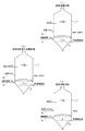
本発明の流動層式焼却装置の実施の形態は、図1に示すように、流動媒体としての砂を収容して、被焼却物として脱水汚泥を焼却する流動層炉本体1を、内面に耐熱耐摩耗性特殊レンガ及び耐火キャスタブルを内張りし、外側には放熱量を最小限に抑える耐熱キャスタブルを施して構成してある。
As shown in FIG. 1, the embodiment of the fluidized bed incinerator of the present invention contains a fluidized bed furnace
前記流動層炉本体1内には、下部に砂層部2が、上部にはフリーボードFBと呼ばれる可燃性ガスの燃焼空間が形成され、砂層部2の下部には、流動用空気を吹き込んで砂の均一流動化を可能にすると共に、燃焼用空気を供給する空気供給手段を兼用した分散パイプ3を設け、流動層炉本体1における流動媒体収容空間である砂層部2に補助燃料を供給する補助燃料供給手段としてメインバーナ4とは別に助燃バーナ5を設け、砂層部2に脱水汚泥を投入する投入手段としてケーキ投入機6を設けてある。
In the fluidized bed furnace
次に、前記流動層式焼却装置の運転制御方法について説明する。
図2(a)〜図2(c)に示すように、前記ケーキ投入機6によって被焼却物を砂層部2に投入する前に、燃焼温度に基づいて砂層部2に補助燃料と燃焼用空気を供給しながら砂層部2を所定温度に制御する燃焼準備段階(図2(a))を設け、ケーキ投入機6によって脱水汚泥を砂層部2に投入し始めてから、燃焼温度に基づいて脱水汚泥に対する補助燃料と燃焼用空気とを供給する定常運転段階(図2(c))の前に、焼却準備段階から定常運転段階に至るまでの脱水汚泥の投入開始直前に、助燃バーナ5による単位時間当たりの第2補助燃料供給量を、燃焼温度に基づく制御を行わずに、燃焼準備段階の単位時間当たりの第1補助燃料供給量及び定常運転段階の単位時間当たりの第3補助燃料供給量よりも予め決められた設定量多くする被焼却物受入準備段階(図2(b))を設けて、炉立ち上げ時の制御が適切に出来るようにしてある。
Next, the operation control method of the fluidized bed incinerator will be described.
As shown in FIGS. 2 (a) to 2 (c), the auxiliary fuel and combustion air are added to the
尚、前記燃焼温度に基づく制御とは、砂層部2の温度を直接測定して、その測定温度に基づいて行う制御や、フリーボードFBの温度測定値や、炉外に排出される排ガスの温度計測に基づいて行われる制御であっても良い。
また、前記脱水汚泥の投入開始直前とは、例えば、汚泥供給ポンプの起動時や、ケーキ投入機の運転開始時とするものである。
The control based on the combustion temperature refers to the control performed by directly measuring the temperature of the
The term “immediately before the start of the addition of the dewatered sludge” refers to, for example, the time when the sludge supply pump is activated or the time when the operation of the cake feeder is started.
つまり、燃焼準備段階で、砂層部2は800℃〜830℃に調整されることにより、フリーボードFBは約800℃になり(この時点で、補助燃料は図3でAの単位時間当たりの第1補助燃焼供給量を供給)、脱水汚泥投入直前の被焼却物受入準備段階では、図3に示すように、補助燃料をAからBの単位時間当たりの第2補助燃料供給量に増量することにより、砂層部2は830℃〜850度に上昇すると共に、フリーボードFBは830℃〜850℃に上昇する。結局、炉内の砂層部2とフリーボードFBのいずれかを、830℃〜850℃までにするのが良いが、最高900℃まで上げても良い
That is, in the combustion preparation stage, the
そして、脱水汚泥投入開始後の定常運転段階では、図3に示すように、補助燃料は、第1補助燃料供給量よりも多いZで示す単位時間当たりの第3補助燃料供給量であっても、脱水汚泥中の水分の気化に熱エネルギーが消費されるために、砂層部2は約750℃になり、汚泥から熱分解により発生した可燃性ガスの燃焼により、フリーボードFBでは昇温して約850℃で安定期に入る。
Then, in the steady operation stage after the start of the dewatered sludge input, as shown in FIG. 3, the auxiliary fuel may be the third auxiliary fuel supply amount per unit time indicated by Z which is larger than the first auxiliary fuel supply amount. Because the heat energy is consumed for vaporizing the water in the dewatered sludge, the
尚、本発明の実施形態の流動層式焼却装置において、特に定常運転段階での運転制御は、燃焼温度に基づくフィードバック制御が基本である。
つまり、フィードフォワード制御では、一般的に被焼却物としての汚泥の焼却に、水分や可燃物の影響が大きいために、その投入する汚泥の含水量や可燃物量の計測が、リアルタイムに必要となり、短時間では精度の高い計測が困難で、制御遅れは避けられないものであった。そのために、安価で迅速な制御が可能なフィードバック制御が、現実的に行われている。
In the fluidized bed incinerator according to the embodiment of the present invention, the operation control particularly in the steady operation stage is basically feedback control based on the combustion temperature.
In other words, in feed-forward control, in general, the incineration of sludge as an incinerator is greatly affected by moisture and combustible materials. It was difficult to measure with high accuracy in a short time, and control delay was inevitable. For this reason, feedback control that enables inexpensive and quick control is practically performed.
〔実施例〕
次に、本発明の実施形態による運転方法で発生する窒素酸化ガス(NOX)や一酸化炭素ガス(CO)やシアン化水素ガス(HCN)の量と、従来技術による窒素酸化ガス(NOX)や一酸化炭素ガス(CO)やシアン化水素ガス(HCN)の発生量と、の比較実験を示す。
〔Example〕
Then, the amount of NOx gas generated by the driving method according to an embodiment of the present invention (NO X) and carbon monoxide gas (CO) and hydrogen cyanide gas (HCN), the prior art nitrogen oxide gas (NO X) Ya Comparison experiments with the generation amounts of carbon monoxide gas (CO) and hydrogen cyanide gas (HCN) are shown.
表1に、本発明に基づく流動層式焼却炉での立ち上げ制御の実験を行った結果が示され、その結果を、図4にグラフとして表した。これに対して、比較実験として、従来技術の制御方法で炉の立ち上げ制御を行って、その結果が表2に示され、図5にグラフとして表してある。尚、補助燃料の供給量(%)は、定常運転段階の定格の補助燃料を、100%として、それを基準とした値である。 Table 1 shows the results of experiments on startup control in a fluidized bed incinerator based on the present invention, and the results are shown as a graph in FIG. On the other hand, as a comparative experiment, the start-up control of the furnace was performed by the control method of the prior art, and the result is shown in Table 2 and shown as a graph in FIG. The supply amount (%) of the auxiliary fuel is a value based on 100% of the rated auxiliary fuel in the steady operation stage.

すなわち、本発明の実験結果では、シアン化水素(HCN)ガスの発生は、ほとんどなく、また、窒素酸化ガス(NOX)の発生も、発生濃度変化のピークはあるものの、かなり抑えられている。これに対し、比較実験例では、シアン化水素(HCN)ガスの発生量のみならず、窒素酸化ガスの発生量も多いことが分かる。 That is, in the experimental results of the present invention, there is almost no generation of hydrogen cyanide (HCN) gas, and the generation of nitrogen oxide gas (NO x ) is considerably suppressed although there is a peak in the generated concentration change. In contrast, in the comparative experimental example, it can be seen that not only the amount of hydrogen cyanide (HCN) gas generated but also the amount of nitrogen oxidizing gas generated is large.
〔別実施の形態〕
第1補助燃料供給量よりも設定量多くする被焼却物受入準備段階は、被焼却物の投入開始直前以外に、被焼却物の投入開始直前から、投入開始直後の炉内で発生する窒素酸化ガス(NOX)の濃度のピークが出るまでの間であれば、窒素酸化ガス(NOX)とシアン化水素ガス(HCN)の発生量を抑制できる。
[Another embodiment]
Nitrogen oxidation that occurs in the furnace immediately after the start of the injection from immediately before the start of the introduction of the incinerator, in addition to immediately before the start of the introduction of the incineration, in addition to the start of the introduction of the incinerator. The amount of generation of nitrogen oxidizing gas (NO X ) and hydrogen cyanide gas (HCN) can be suppressed as long as the gas (NO X ) concentration peak is reached.
尚、第2補助燃料供給量は、第1補助燃料供給量よりは多いが、第3補助燃料供給量よりも少ない場合も、被焼却物の性状によっては、あっても良い。 The second auxiliary fuel supply amount is larger than the first auxiliary fuel supply amount, but may be smaller than the third auxiliary fuel supply amount depending on the properties of the incinerated material.
前記流動層式焼却装置には、手動による焼却制御を行う以外に、補助燃料供給手段5による単位時間当たりの補助燃料供給量と、空気供給手段3による空気供給量とを調整して流動媒体収容空間2の温度を制御する燃焼制御手段を設け、投入手段6によって脱水汚泥等の被焼却物を流動媒体収容空間2に投入する前に、燃焼温度に基づいて流動媒体収容空間2に補助燃料と燃焼用空気を供給しながら流動媒体収容空間2を所定の温度に制御おく燃焼準備段階と、投入手段6によって被焼却物を流動媒体収容空間2に投入し始めてから燃焼温度に基づいて被焼却物に対する補助燃料と燃焼用空気とを供給する定常運転段階と、燃焼準備段階から定常運転段階に至るまでの被焼却物の投入開始直前に、補助燃料供給手段5による単位時間当たりの第2補助燃料供給量を、燃焼準備段階の第1補助燃料供給量よりも設定量多くする被焼却物受入準備段階とを、順次自動的に操作するプロセス制御部を燃焼制御手段に設けて、自動制御されるようにしてあってもよい。
The fluidized-bed incinerator accommodates the fluid medium by adjusting the auxiliary fuel supply amount per unit time by the auxiliary fuel supply means 5 and the air supply amount by the air supply means 3 in addition to performing manual incineration control. Combustion control means for controlling the temperature of the
前記被焼却物として、脱水汚泥の例を示したが、例えば、含水率の高いゴミの焼却に本実施形態の装置及び運転制御が、使用されても良いのは言うまでもない。 Although the example of the dewatered sludge was shown as the said to-be-incinerated material, it cannot be overemphasized that the apparatus and operation control of this embodiment may be used for incineration of garbage with a high moisture content, for example.
1 流動層炉本体
2 砂層部(流動媒体収容空間)
3 分散パイプ(空気供給手段)
5 助燃バーナ(補助燃料供給手段)
6 ケーキ投入機(投入手段)
1 Fluidized
3 Dispersion pipe (air supply means)
5 Auxiliary burner (auxiliary fuel supply means)
6 Cake feeding machine (loading means)
Claims (4)
Priority Applications (1)
| Application Number | Priority Date | Filing Date | Title |
|---|---|---|---|
| JP2008222327A JP5406482B2 (en) | 2008-08-29 | 2008-08-29 | Operation control method for fluidized bed incinerator and fluidized bed incinerator |
Applications Claiming Priority (1)
| Application Number | Priority Date | Filing Date | Title |
|---|---|---|---|
| JP2008222327A JP5406482B2 (en) | 2008-08-29 | 2008-08-29 | Operation control method for fluidized bed incinerator and fluidized bed incinerator |
Publications (2)
| Publication Number | Publication Date |
|---|---|
| JP2010054169A true JP2010054169A (en) | 2010-03-11 |
| JP5406482B2 JP5406482B2 (en) | 2014-02-05 |
Family
ID=42070287
Family Applications (1)
| Application Number | Title | Priority Date | Filing Date |
|---|---|---|---|
| JP2008222327A Active JP5406482B2 (en) | 2008-08-29 | 2008-08-29 | Operation control method for fluidized bed incinerator and fluidized bed incinerator |
Country Status (1)
| Country | Link |
|---|---|
| JP (1) | JP5406482B2 (en) |
Cited By (3)
| Publication number | Priority date | Publication date | Assignee | Title |
|---|---|---|---|---|
| JP2013194951A (en) * | 2012-03-16 | 2013-09-30 | Kubota Corp | Fluidized bed incinerator, combustion control device and operating method for fluidized bed incinerator |
| WO2013146597A1 (en) * | 2012-03-26 | 2013-10-03 | 月島機械株式会社 | Activation method for pressurized fluidized furnace system |
| CN103375806A (en) * | 2012-04-26 | 2013-10-30 | 月岛机械株式会社 | Processed object moving method for pressurizing flowing furnace system |
Citations (1)
| Publication number | Priority date | Publication date | Assignee | Title |
|---|---|---|---|---|
| JP2001074222A (en) * | 1999-09-07 | 2001-03-23 | Kubota Corp | Method and apparatus for controlling temperature in fluidized bed incinerator |
-
2008
- 2008-08-29 JP JP2008222327A patent/JP5406482B2/en active Active
Patent Citations (1)
| Publication number | Priority date | Publication date | Assignee | Title |
|---|---|---|---|---|
| JP2001074222A (en) * | 1999-09-07 | 2001-03-23 | Kubota Corp | Method and apparatus for controlling temperature in fluidized bed incinerator |
Cited By (9)
| Publication number | Priority date | Publication date | Assignee | Title |
|---|---|---|---|---|
| JP2013194951A (en) * | 2012-03-16 | 2013-09-30 | Kubota Corp | Fluidized bed incinerator, combustion control device and operating method for fluidized bed incinerator |
| WO2013146597A1 (en) * | 2012-03-26 | 2013-10-03 | 月島機械株式会社 | Activation method for pressurized fluidized furnace system |
| JP2013200086A (en) * | 2012-03-26 | 2013-10-03 | Tsukishima Kikai Co Ltd | Start-up method of pressure fluidized bed furnace system |
| CN104204670A (en) * | 2012-03-26 | 2014-12-10 | 月岛机械株式会社 | Activation method for pressurized fluidized furnace system |
| KR20140147830A (en) * | 2012-03-26 | 2014-12-30 | 츠키시마기카이가부시키가이샤 | Activation method for pressurized fluidized furnace system |
| CN104204670B (en) * | 2012-03-26 | 2018-04-20 | 月岛机械株式会社 | Method for starting pressurised fluidized bed incinerator system |
| US10006631B2 (en) | 2012-03-26 | 2018-06-26 | Tsukishima Kikai Co., Ltd. | Method for starting up pressurized fluidized bed incinerator system |
| KR102067302B1 (en) * | 2012-03-26 | 2020-01-16 | 츠키시마기카이가부시키가이샤 | Activation method for pressurized fluidized furnace system |
| CN103375806A (en) * | 2012-04-26 | 2013-10-30 | 月岛机械株式会社 | Processed object moving method for pressurizing flowing furnace system |
Also Published As
| Publication number | Publication date |
|---|---|
| JP5406482B2 (en) | 2014-02-05 |
Similar Documents
| Publication | Publication Date | Title |
|---|---|---|
| EP2206953A1 (en) | Fluidized-bed incinerator and method of fluidized-bed incineration of sludge with the same | |
| JP5406482B2 (en) | Operation control method for fluidized bed incinerator and fluidized bed incinerator | |
| JP2011079890A (en) | Multi-stage screw carbonization furnace | |
| JP2009250571A (en) | Starting method of circulating fluidized bed furnace | |
| JP2009243714A (en) | Pyrolysis gas treatment method and device in sludge carbonizing treatment equipment | |
| EP2660302A1 (en) | Gasification melting furnace and treating method for combustible material using the same | |
| JP2010275623A (en) | Method for operating blast furnace | |
| FI123166B (en) | METHOD FOR ADJUSTING COMBUSTION IN THE CFB BOILER PLANT | |
| WO2013191109A1 (en) | Circulating-type multi-layer furnace | |
| RU2019102263A (en) | METHOD FOR OPERATING THE FURNACE OF BETWEEN OPERATION, INCLUDING PREHEATING OF THE FLUID MEDIUM ABOVE THE FLOW RELATIVE TO THE FURNACE | |
| JP5509171B2 (en) | Combustion control device for gasification melting furnace and combustion control method for gasification melting furnace | |
| JP5425983B2 (en) | Gas temperature control method and gas temperature control device for gasification melting furnace | |
| JP2003021314A (en) | Method of starting gasifying furnace | |
| JP2005009830A (en) | Dry distillation gasification incineration method of wastes | |
| KR101242696B1 (en) | Burning control method of combustion chamber | |
| JP2008137861A (en) | Glass melting furnace | |
| JP2005146188A (en) | Biomass gas generation furnace | |
| JP3142548U (en) | Biomass combustion equipment | |
| JP2019199983A (en) | Incinerator structure, and method of controlling inside temperature of incinerator | |
| JP2007212119A (en) | Biomass combustion device | |
| JP2020085282A (en) | Industrial furnace and combustion control method for industrial furnace | |
| JP2000081206A (en) | Starting control method, stopping control method, and starting/stopping control device of partial combustion furnace | |
| JP2018091574A (en) | Incineration apparatus | |
| JP2007254605A (en) | Garbage carbonization apparatus | |
| JP4139360B2 (en) | Waste gasification incineration treatment method of waste |
Legal Events
| Date | Code | Title | Description |
|---|---|---|---|
| A621 | Written request for application examination |
Free format text: JAPANESE INTERMEDIATE CODE: A621 Effective date: 20110323 |
|
| A977 | Report on retrieval |
Free format text: JAPANESE INTERMEDIATE CODE: A971007 Effective date: 20130318 |
|
| A131 | Notification of reasons for refusal |
Free format text: JAPANESE INTERMEDIATE CODE: A131 Effective date: 20130328 |
|
| A521 | Written amendment |
Free format text: JAPANESE INTERMEDIATE CODE: A523 Effective date: 20130524 |
|
| TRDD | Decision of grant or rejection written | ||
| A01 | Written decision to grant a patent or to grant a registration (utility model) |
Free format text: JAPANESE INTERMEDIATE CODE: A01 Effective date: 20131003 |
|
| A61 | First payment of annual fees (during grant procedure) |
Free format text: JAPANESE INTERMEDIATE CODE: A61 Effective date: 20131101 |
|
| R150 | Certificate of patent or registration of utility model |
Ref document number: 5406482 Country of ref document: JP Free format text: JAPANESE INTERMEDIATE CODE: R150 |