JP2010053765A - Heat pump device and reciprocating compressor for refrigerant - Google Patents
Heat pump device and reciprocating compressor for refrigerant Download PDFInfo
- Publication number
- JP2010053765A JP2010053765A JP2008219221A JP2008219221A JP2010053765A JP 2010053765 A JP2010053765 A JP 2010053765A JP 2008219221 A JP2008219221 A JP 2008219221A JP 2008219221 A JP2008219221 A JP 2008219221A JP 2010053765 A JP2010053765 A JP 2010053765A
- Authority
- JP
- Japan
- Prior art keywords
- refrigerant
- discharge
- refrigerant liquid
- discharge chamber
- chamber
- Prior art date
- Legal status (The legal status is an assumption and is not a legal conclusion. Google has not performed a legal analysis and makes no representation as to the accuracy of the status listed.)
- Granted
Links
- 239000003507 refrigerant Substances 0.000 title claims abstract description 257
- 239000007788 liquid Substances 0.000 claims abstract description 184
- 238000001704 evaporation Methods 0.000 claims abstract description 15
- 230000008020 evaporation Effects 0.000 claims abstract description 14
- 238000002347 injection Methods 0.000 claims description 24
- 239000007924 injection Substances 0.000 claims description 24
- 238000001816 cooling Methods 0.000 claims description 15
- 238000009834 vaporization Methods 0.000 claims description 12
- 230000008016 vaporization Effects 0.000 claims description 12
- 239000011810 insulating material Substances 0.000 claims description 7
- 230000006835 compression Effects 0.000 claims description 4
- 238000007906 compression Methods 0.000 claims description 4
- 230000002093 peripheral effect Effects 0.000 claims description 4
- 238000011144 upstream manufacturing Methods 0.000 claims description 4
- 238000005057 refrigeration Methods 0.000 description 24
- 230000000694 effects Effects 0.000 description 19
- 230000008014 freezing Effects 0.000 description 12
- 238000007710 freezing Methods 0.000 description 12
- 239000000498 cooling water Substances 0.000 description 11
- 238000010586 diagram Methods 0.000 description 9
- 230000007423 decrease Effects 0.000 description 8
- 239000002826 coolant Substances 0.000 description 7
- 239000003921 oil Substances 0.000 description 7
- 238000009413 insulation Methods 0.000 description 6
- 230000009897 systematic effect Effects 0.000 description 6
- 239000010687 lubricating oil Substances 0.000 description 4
- 239000004071 soot Substances 0.000 description 4
- 238000010438 heat treatment Methods 0.000 description 3
- QGZKDVFQNNGYKY-UHFFFAOYSA-N Ammonia Chemical compound N QGZKDVFQNNGYKY-UHFFFAOYSA-N 0.000 description 2
- 235000017166 Bambusa arundinacea Nutrition 0.000 description 2
- 235000017491 Bambusa tulda Nutrition 0.000 description 2
- 241001330002 Bambuseae Species 0.000 description 2
- 235000015334 Phyllostachys viridis Nutrition 0.000 description 2
- 239000011425 bamboo Substances 0.000 description 2
- 230000003247 decreasing effect Effects 0.000 description 2
- 238000003912 environmental pollution Methods 0.000 description 2
- 239000010419 fine particle Substances 0.000 description 2
- 239000013529 heat transfer fluid Substances 0.000 description 2
- 238000005192 partition Methods 0.000 description 2
- 230000001105 regulatory effect Effects 0.000 description 2
- 238000009833 condensation Methods 0.000 description 1
- 230000005494 condensation Effects 0.000 description 1
- 230000006866 deterioration Effects 0.000 description 1
- 238000007599 discharging Methods 0.000 description 1
- 230000007613 environmental effect Effects 0.000 description 1
- 238000009434 installation Methods 0.000 description 1
- 239000000463 material Substances 0.000 description 1
- 239000005022 packaging material Substances 0.000 description 1
- 238000004806 packaging method and process Methods 0.000 description 1
- 230000000717 retained effect Effects 0.000 description 1
- 230000001629 suppression Effects 0.000 description 1
- 230000002195 synergetic effect Effects 0.000 description 1
- 238000010792 warming Methods 0.000 description 1
Images


Landscapes
- Compressor (AREA)
Abstract
Description
本発明は、冷凍装置等のヒートポンプ装置に組み込んだ往復動型圧縮機から吐出する冷媒ガスの温度上昇を抑えることにより、往復動型圧縮機の体積効率を向上させ、さらには、該往復動型圧縮機が組み込まれたヒートポンプ装置の能力向上を可能にしたものである。 The present invention improves the volumetric efficiency of a reciprocating compressor by suppressing the temperature rise of refrigerant gas discharged from a reciprocating compressor incorporated in a heat pump apparatus such as a refrigeration apparatus. This makes it possible to improve the capacity of a heat pump device incorporating a compressor.
従来、往復動型圧縮機では、ケーシング内に吸入ガス通路及び吐出ガス通路を設けるのが一般的である。冷凍装置等のヒートポンプ装置に組み込まれた往復動型圧縮機では、高温の吐出ガスと低温の吸入ガスがケーシングの壁面を介して熱交換し、吸入ガスがシリンダに吸い込まれるまでに吸入ガスの温度が上昇してしまう。そのため、吸入ガスがシリンダに吸入される前に膨張し、比容積が大きくなり、循環質量流量が無視できないほど減少する。従って、圧縮機での体積効率の低下を招き、往復動型圧縮機が組み込まれた冷凍装置の冷凍能力又はヒートポンプ装置の加熱能力を低下させることになる。 Conventionally, in a reciprocating compressor, an intake gas passage and a discharge gas passage are generally provided in a casing. In a reciprocating compressor incorporated in a heat pump device such as a refrigeration device, the temperature of the suction gas is increased until the high-temperature discharge gas and the low-temperature suction gas exchange heat through the wall surface of the casing and the suction gas is sucked into the cylinder. Will rise. Therefore, the suction gas expands before being sucked into the cylinder, the specific volume increases, and the circulating mass flow rate decreases to a degree that cannot be ignored. Therefore, the volumetric efficiency in the compressor is reduced, and the refrigerating capacity of the refrigerating apparatus incorporating the reciprocating compressor or the heating capacity of the heat pump apparatus is decreased.
特に、アンモニアガスは、比熱比が比較的大きいため、吐出温度が高く、また、図11に示すように、温度上昇に対して、比容積が大きくなる特性をもっている。このような熱媒を用いる場合は、圧縮機のケーシング内部での吸入ガスの加熱(温度上昇)をできるだけ抑える必要がある。 In particular, ammonia gas has a relatively large specific heat ratio, so that the discharge temperature is high, and as shown in FIG. 11, the specific volume increases as the temperature rises. When such a heat medium is used, it is necessary to suppress the heating (temperature rise) of the suction gas inside the casing of the compressor as much as possible.
特許文献1(特開2000−18154号公報)には、往復動型圧縮機において、圧縮時のシリンダ室内温度が過度に高くなることを抑えて、潤滑油の劣化や焼付きの問題を解消するための手段が開示されている。この手段は、ピストンが収納された複数のシリンダ室の周囲に空洞部を設け、該空洞部に冷却用媒体としてアキュムレータから帰還した帰還冷媒を導入することにより、シリンダ室を冷却する手段が開示されている。シリンダ室を冷却した帰還冷媒は連通孔を介して吸入室に導出される。 In Patent Document 1 (Japanese Patent Laid-Open No. 2000-18154), in a reciprocating compressor, the temperature in the cylinder chamber during compression is prevented from becoming excessively high, and the problem of deterioration and seizure of lubricating oil is solved. Means for disclosing are disclosed. This means discloses means for cooling the cylinder chamber by providing a cavity around the plurality of cylinder chambers in which the pistons are housed, and introducing a return refrigerant returned from the accumulator as a cooling medium into the cavity. ing. The return refrigerant that has cooled the cylinder chamber is led to the suction chamber through the communication hole.
特許文献1に開示された手段では、シリンダの周囲に空洞部を設け、該空洞部に帰還冷媒を導入することによって、シリンダの冷却を行なうものである。従って、吐出ガスを冷却するものではないため、吸入ガスがシリンダに吸入される前に、吸入ガスと吐出ガスがケーシングの壁面を通して熱交換してしまい、シリンダに吸入される前の吸入ガスの温度上昇を防止できない。従って、圧縮機での体積効率の低下を招き、往復動型圧縮機が組み込まれた冷凍装置の冷凍能力又はヒートポンプ装置の加熱能力を低下させることになる。 In the means disclosed in Patent Document 1, a cavity is provided around the cylinder, and the return refrigerant is introduced into the cavity to cool the cylinder. Therefore, since the discharge gas is not cooled, before the suction gas is sucked into the cylinder, the suction gas and the discharge gas exchange heat through the wall surface of the casing, and the temperature of the suction gas before being sucked into the cylinder. The rise cannot be prevented. Therefore, the volumetric efficiency in the compressor is reduced, and the refrigerating capacity of the refrigerating apparatus incorporating the reciprocating compressor or the heating capacity of the heat pump apparatus is decreased.
また、シリンダ室の周囲に冷却用媒体を導入する空洞部を設けるため、圧縮機が大型化かつ重量化してしまうとともに、該空洞部に多量の冷却用媒体を供給するために、圧縮機が組み込まれた冷凍装置等のヒートポンプ装置の能力を低下させてしまうという問題がある。 In addition, since the cavity for introducing the cooling medium is provided around the cylinder chamber, the compressor is increased in size and weight, and the compressor is incorporated to supply a large amount of the cooling medium to the cavity. There is a problem that the capability of the heat pump apparatus such as the refrigeration apparatus is reduced.
本発明は、かかる従来技術の課題に鑑み、簡素な構成で、往復動型圧縮機の吐出ガス温度を低下させることにより、往復動型圧縮機の体積効率の低下や、往復動型圧縮機が組み込まれたヒートポンプ装置の能力低下を防止することを目的とする。 In view of the problems of the prior art, the present invention reduces the volume efficiency of the reciprocating compressor and reduces the reciprocating compressor by reducing the discharge gas temperature of the reciprocating compressor with a simple configuration. It aims at preventing the capability fall of the incorporated heat pump apparatus.
かかる目的を達成するため、本発明のヒートポンプ装置は、
冷媒循環路に往復動型圧縮機、凝縮器、膨張弁及び蒸発器を介設したヒートポンプサイクルを構成してなるヒートポンプ装置において、
凝縮器で凝縮した冷媒液の一部を往復動型圧縮機のシリンダ上部組立体に設けられた吐出室又は該吐出室に連通した吐出空間に戻す冷媒液戻し流路を設け、
該冷媒液戻し流路を介して該吐出室又は吐出空間に冷媒液の一部を供給し、冷媒液の蒸発潜熱により該吐出室又は吐出空間を冷却するように構成したものである。
In order to achieve such an object, the heat pump device of the present invention comprises:
In a heat pump device comprising a heat pump cycle in which a reciprocating compressor, a condenser, an expansion valve and an evaporator are interposed in a refrigerant circuit,
A refrigerant liquid return passage is provided for returning a part of the refrigerant liquid condensed by the condenser to a discharge chamber provided in the cylinder upper assembly of the reciprocating compressor or a discharge space communicating with the discharge chamber,
A part of the refrigerant liquid is supplied to the discharge chamber or the discharge space via the refrigerant liquid return flow path, and the discharge chamber or the discharge space is cooled by the latent heat of vaporization of the refrigerant liquid.
本発明のヒートポンプ装置では、往復動型圧縮機のシリンダ上部組立体に設けられた吐出室から吐出しその後凝縮器で凝縮した冷媒液の一部を吐出室又は該吐出空間に戻すようにする。そして、吐出室又は該吐出空間で該冷媒液を吐出ガスの熱で蒸発させ、吐出ガスから蒸発潜熱を奪うことによって、吐出室又は該吐出空間を冷却する。吐出室又は該吐出空間を冷却することによって、吐出室又は該吐出空間から吸入室又はガス通路への熱伝達を抑制するようにしたものである。 In the heat pump device of the present invention, a part of the refrigerant liquid discharged from the discharge chamber provided in the cylinder upper assembly of the reciprocating compressor and then condensed by the condenser is returned to the discharge chamber or the discharge space. Then, the refrigerant liquid is evaporated with the heat of the discharge gas in the discharge chamber or the discharge space, and the discharge chamber or the discharge space is cooled by removing the latent heat of evaporation from the discharge gas. By cooling the discharge chamber or the discharge space, heat transfer from the discharge chamber or the discharge space to the suction chamber or the gas passage is suppressed.
これによって、シリンダに吸入される前の冷媒ガスの温度上昇を防止できる。従って、体積膨張を抑制して、往復動型圧縮機の体積効率の低下を防ぎ、往復動型圧縮機が組み込まれたヒートポンプ装置の能力低下を抑制することができる。
このように、冷媒の蒸発潜熱で吐出室又は該吐出室に連通した吐出空間を冷却でき、冷却水等を使用しないため、砂漠地帯など冷却水がない所でも適用できる。そのため、低コストで環境問題も起こらない。
Thereby, the temperature rise of the refrigerant gas before being sucked into the cylinder can be prevented. Therefore, volume expansion can be suppressed, the volumetric efficiency of the reciprocating compressor can be prevented from being lowered, and the capacity reduction of the heat pump apparatus incorporating the reciprocating compressor can be suppressed.
In this way, the discharge chamber or the discharge space communicating with the discharge chamber can be cooled by the latent heat of vaporization of the refrigerant, and since cooling water or the like is not used, the present invention can be applied even in a desert area where there is no cooling water. Therefore, environmental problems do not occur at low cost.
本発明のヒートポンプ装置において、前記吐出室又は吐出空間に冷媒液戻し流路に接続された噴射ノズルを設け、冷媒液を該噴射ノズルから該吐出室又は吐出空間に噴射するように構成するとよい。これによって、吐出室又は該吐出室に連通した吐出空間での冷媒液の蒸発を促進でき、冷却効果を高めることができる。 In the heat pump device of the present invention, an injection nozzle connected to the refrigerant liquid return channel may be provided in the discharge chamber or the discharge space, and the refrigerant liquid may be injected from the injection nozzle into the discharge chamber or the discharge space. Accordingly, evaporation of the refrigerant liquid in the discharge chamber or the discharge space communicating with the discharge chamber can be promoted, and the cooling effect can be enhanced.
本発明のヒートポンプ装置において、往復動型圧縮機が低段圧縮機と高段圧縮機とからなる多段圧縮機である場合、高段圧縮機から吐出され凝縮器で凝縮した冷媒液の一部を低段圧縮機の吐出室又は該吐出室に連通した吐出空間に戻す冷媒液戻し流路を設け、該冷媒液戻し流路を介して低段圧縮機の該吐出室又は吐出空間に冷媒液の一部を供給するように構成するとよい。 In the heat pump device of the present invention, when the reciprocating compressor is a multi-stage compressor including a low-stage compressor and a high-stage compressor, a part of the refrigerant liquid discharged from the high-stage compressor and condensed by the condenser is used. A refrigerant liquid return passage is provided to return to the discharge chamber of the low-stage compressor or the discharge space communicating with the discharge chamber, and the refrigerant liquid is supplied to the discharge chamber or the discharge space of the low-stage compressor via the refrigerant liquid return passage. It is good to comprise so that a part may be supplied.
高段圧縮機から吐出され凝縮器で凝縮された冷媒液は、低段圧縮機の吐出室又は該吐出室に連通した吐出空間より高圧であるので、増圧機を用いることなく、低段圧縮機の該吐出室又は吐出空間に供給できる。このため、冷媒液を供給するための動力や機器類が不要になる。 Since the refrigerant liquid discharged from the high-stage compressor and condensed in the condenser is higher in pressure than the discharge chamber of the low-stage compressor or the discharge space communicating with the discharge chamber, the low-stage compressor is not used. Can be supplied to the discharge chamber or discharge space. This eliminates the need for power and equipment for supplying the refrigerant liquid.
前記構成に加えて、高段圧縮機から吐出され凝縮器で凝縮した冷媒液の一部を高段圧縮機の該吐出室又は吐出空間に戻す第2の冷媒液戻し流路を設けると共に、該第2の冷媒液戻し流路に増圧機を介設し、第2の冷媒液戻し流路を介して高段圧縮機の該吐出室又は吐出空間に冷媒液の一部を供給するように構成してもよい。
高段圧縮機の該吐出室又は吐出空間に凝縮器で凝縮した熱媒液の一部を供給する場合は、高段圧縮機の該吐出室又は吐出空間と凝縮器は同一圧力であるので、熱媒液戻し流路に例えば液ポンプ等の増圧機を介設する必要がある。
これによって、低段圧縮機及び高段圧縮機の両方の吸入ガスを冷却できる。
In addition to the above-described configuration, a second refrigerant liquid return flow path for returning a part of the refrigerant liquid discharged from the high stage compressor and condensed by the condenser to the discharge chamber or the discharge space of the high stage compressor is provided. A pressure intensifier is provided in the second refrigerant liquid return flow path, and a part of the refrigerant liquid is supplied to the discharge chamber or the discharge space of the high-stage compressor via the second refrigerant liquid return flow path. May be.
When supplying a part of the heat transfer fluid condensed in the condenser to the discharge chamber or discharge space of the high-stage compressor, the discharge chamber or discharge space of the high-stage compressor and the condenser have the same pressure. For example, a pressure booster such as a liquid pump needs to be interposed in the heat medium liquid return channel.
Thereby, the intake gas of both the low stage compressor and the high stage compressor can be cooled.
また、本発明のヒートポンプ装置において、凝縮器と膨張弁間の冷媒循環路に冷媒液熱交換器を介設し、該冷媒液熱交換器に低段圧縮機から吐出した冷媒ガスを高段圧縮機の該吐出室又は吐出空間に導く冷媒循環路を接続して、凝縮器から出た冷媒液を低段圧縮機から吐出された冷媒ガスで冷却するように構成するとよい。
これによって、冷媒循環路を凝縮器から膨張弁に向う冷媒液を、該冷媒液熱交換器で低段圧縮機から吐出され冷却された冷媒ガスで冷却するようにしているので、冷凍装置等のヒートポンプ装置の能力を向上できる。
In the heat pump device of the present invention, a refrigerant liquid heat exchanger is interposed in the refrigerant circulation path between the condenser and the expansion valve, and the refrigerant gas discharged from the low-stage compressor is compressed into the refrigerant liquid heat exchanger by high-stage compression. A refrigerant circulation path that leads to the discharge chamber or the discharge space of the machine may be connected so that the refrigerant liquid discharged from the condenser is cooled by the refrigerant gas discharged from the low-stage compressor.
As a result, the refrigerant liquid flowing from the condenser to the expansion valve in the refrigerant circulation path is cooled by the refrigerant gas discharged from the low-stage compressor and cooled by the refrigerant liquid heat exchanger. The capacity of the heat pump device can be improved.
なお、前記構成において、冷媒液熱交換器を冷媒液戻し流路又は第2の冷媒液戻し流路の上流側の冷媒循環路に介設し、冷媒液熱交換器で冷却した冷媒液の一部を冷媒液戻し流路又は第2の冷媒液戻し流路に供給するように構成してもよい。
これによって、該冷媒液熱交換器で冷却された冷媒液を低段圧縮機又は高段圧縮機の該吐出室又は吐出空間に供給できるので、吐出ガスの冷却効果をさらに高める高段圧縮機とができる。
In the above configuration, the refrigerant liquid heat exchanger is interposed in the refrigerant circulation path on the upstream side of the refrigerant liquid return flow path or the second refrigerant liquid return flow path, and one of the refrigerant liquid cooled by the refrigerant liquid heat exchanger. You may comprise so that a part may be supplied to a refrigerant | coolant liquid return flow path or a 2nd refrigerant | coolant liquid return flow path.
Accordingly, the refrigerant liquid cooled by the refrigerant liquid heat exchanger can be supplied to the discharge chamber or the discharge space of the low-stage compressor or the high-stage compressor, so that the high-stage compressor further enhances the cooling effect of the discharge gas, Can do.
また、本発明のヒートポンプ装置において、凝縮器と膨張弁間の冷媒循環路に中間冷却器を介設し、該中間冷却器に低段圧縮機から吐出した冷媒ガスを高段圧縮機の該吐出室又は吐出空間に導く冷媒循環路を接続し、該中間冷却器で凝縮器から出た冷媒液の一部を蒸発させることにより、凝縮器から出た他の冷媒液及び低段圧縮機から吐出された冷媒ガスを冷却するように構成するとよい。 In the heat pump device of the present invention, an intermediate cooler is interposed in the refrigerant circulation path between the condenser and the expansion valve, and the refrigerant gas discharged from the low-stage compressor is supplied to the intermediate cooler by the discharge of the high-stage compressor. Connecting the refrigerant circulation path leading to the chamber or discharge space, and evaporating a part of the refrigerant liquid from the condenser with the intermediate cooler, thereby discharging from the other refrigerant liquid and the low-stage compressor from the condenser. It is preferable that the refrigerant gas is cooled.
これによって、ヒートポンプ装置の能力を向上できるとともに、中間冷却器で冷却された後の過冷却された高圧の冷媒液の一部を低段圧縮機の該吐出室又は吐出空間に供給できるので、低段圧縮機の吐出ガスの冷却効果をさらに高めることができると共に、冷媒液の供給量を減少できるので、低段圧縮機の該吐出室又は吐出空間に設けられる噴射ノズルを小型化することができる。 As a result, the capacity of the heat pump device can be improved and a part of the supercooled high-pressure refrigerant liquid after being cooled by the intercooler can be supplied to the discharge chamber or the discharge space of the low-stage compressor. The cooling effect of the discharge gas of the stage compressor can be further enhanced and the supply amount of the refrigerant liquid can be reduced, so that the injection nozzle provided in the discharge chamber or the discharge space of the low stage compressor can be reduced in size. .
冷媒として、比熱比が大きいNH3を用いた場合、NH3は温度上昇により比容積が他の冷媒と比べて大きくなる特性がある。シリンダへ吸入される前の吸入ガスの温度上昇による体積膨張が著しい。しかし、本発明を適用すれば、シリンダに吸入される前のNH3ガスの温度上昇を抑えることができるので、ヒートポンプ装置の能力低下を招かない。 When NH 3 having a large specific heat ratio is used as the refrigerant, NH 3 has a characteristic that the specific volume becomes larger than other refrigerants due to a temperature rise. The volume expansion due to the temperature rise of the suction gas before being sucked into the cylinder is remarkable. However, if the present invention is applied, the temperature rise of the NH 3 gas before being sucked into the cylinder can be suppressed, so that the capacity of the heat pump device is not lowered.
次に、前記本発明のヒートポンプ装置に適用可能な第1の本発明の冷媒用往復動型圧縮機は、
シリンダ上部組立体に吸入弁を介してシリンダと連通する吸入室と、吐出弁を介してシリンダと連通する吐出室とを備えてなる冷媒用往復動型圧縮機において、
吐出ガスを凝縮して得られた冷媒液の一部を受け入れる冷媒液供給口を吐出室又は該吐出室に連通した吐出空間に設け、該冷媒液供給口を介して該吐出室又は吐出空間に冷媒液を受け入れ、冷媒液の蒸発潜熱により該吐出室又は吐出空間を冷却するように構成したものである。
Next, the reciprocating compressor for refrigerant of the first invention applicable to the heat pump device of the invention is
In a reciprocating compressor for a refrigerant comprising a suction chamber communicating with a cylinder via a suction valve and a discharge chamber communicating with the cylinder via a discharge valve in a cylinder upper assembly,
A refrigerant liquid supply port for receiving a part of the refrigerant liquid obtained by condensing the discharge gas is provided in the discharge chamber or a discharge space communicating with the discharge chamber, and the discharge chamber or the discharge space is provided via the refrigerant liquid supply port. The refrigerant liquid is received, and the discharge chamber or the discharge space is cooled by the latent heat of vaporization of the refrigerant liquid.
前記構成により、吐出ガスを凝縮して得られた冷媒液の一部を該吐出室又は吐出空間に供給し、該冷媒液の蒸発潜熱で該吐出室又は吐出空間を冷却できる。これによって、該吐出室又は吐出空間の温度上昇をなくし、シリンダに吸入される前の吸入ガスの昇温を防止できるので、吸入ガスの比容積の増大を抑えることができ、体積効率の低下を抑えることができる。従って、往復動型圧縮機が組み込まれたヒートポンプ装置の能力低下を抑制することができる。 With the above configuration, a part of the refrigerant liquid obtained by condensing the discharge gas can be supplied to the discharge chamber or the discharge space, and the discharge chamber or the discharge space can be cooled by the latent heat of vaporization of the refrigerant liquid. As a result, the temperature rise of the discharge chamber or the discharge space can be eliminated and the temperature rise of the suction gas before being sucked into the cylinder can be prevented, so that an increase in the specific volume of the suction gas can be suppressed, and the volume efficiency is reduced. Can be suppressed. Accordingly, it is possible to suppress a decrease in the performance of the heat pump apparatus in which the reciprocating compressor is incorporated.
第1の本発明の冷媒用往復動型圧縮機において、該吐出室又は吐出空間に冷媒液供給口に連通した噴射ノズルを設け、冷媒液を該噴射ノズルを介して該吐出室又は吐出空間に噴射するように構成するとよい。これによって、該吐出室又は吐出空間での冷媒液の蒸発を促進でき、冷却効果を高めることができる。 In the reciprocating compressor for refrigerant according to the first aspect of the present invention, an injection nozzle communicating with the refrigerant liquid supply port is provided in the discharge chamber or the discharge space, and the refrigerant liquid is supplied to the discharge chamber or the discharge space via the injection nozzle. It is good to comprise so that it may inject. Thereby, evaporation of the refrigerant liquid in the discharge chamber or the discharge space can be promoted, and the cooling effect can be enhanced.
また、前記本発明のヒートポンプ装置に適用可能な第2の本発明の冷媒用往復動型圧縮機は、
シリンダ上部組立体に吸入弁を介してシリンダと連通する吸入室と、吐出弁を介してシリンダと連通する吐出室とを備えてなる冷媒用往復動型圧縮機において、
吸入室と吐出室間に断熱材を介装し、吸入室と吐出室間の伝熱を遮断するように構成したものである。
The reciprocating compressor for refrigerant according to the second aspect of the present invention, applicable to the heat pump device according to the present invention,
In a reciprocating compressor for a refrigerant comprising a suction chamber communicating with a cylinder via a suction valve and a discharge chamber communicating with the cylinder via a discharge valve in a cylinder upper assembly,
A heat insulating material is interposed between the suction chamber and the discharge chamber to block heat transfer between the suction chamber and the discharge chamber.
かかる構成によれば、吐出室と吸入室との間に断熱材を介装するという簡易な手段で、吐出室の熱が吸入室に伝達するのを防止できる。これによって、シリンダに吸入される前の冷媒ガスの昇温を防止できるので、該冷媒ガスの比容積の増大を抑え、体積効率の低下を抑えることができる。これによって、往復動型圧縮機が組み込まれたヒートポンプ装置の能力低下を抑制することができる。 According to such a configuration, it is possible to prevent the heat of the discharge chamber from being transmitted to the suction chamber by a simple means of interposing a heat insulating material between the discharge chamber and the suction chamber. Accordingly, the temperature rise of the refrigerant gas before being sucked into the cylinder can be prevented, so that an increase in the specific volume of the refrigerant gas can be suppressed and a decrease in volume efficiency can be suppressed. Thereby, the capability fall of the heat pump apparatus incorporating the reciprocating compressor can be suppressed.
さらに、第1の本発明の往復動型圧縮機と第2の本発明の往復動型圧縮機の構成を組み合わせることにより、吐出室から吸入室への熱伝熱を相乗的に抑制することができる。
即ち、吐出ガスを凝縮して得られた冷媒液の一部を受け入れる冷媒液供給口を該吐出室又は吐出空間に設け、該冷媒液供給口を介して該吐出室又は吐出空間に冷媒液を受け入れ、冷媒液の蒸発潜熱により該吐出室又は吐出空間を冷却するように構成すると共に、吐出室と吸入室との間に断熱材を介装したことにより、吐出室から吸入室への伝熱を効果的に抑えることができる。
Further, by combining the configurations of the reciprocating compressor of the first invention and the reciprocating compressor of the second invention, the heat transfer from the discharge chamber to the suction chamber can be suppressed in a synergistic manner. it can.
That is, a refrigerant liquid supply port for receiving a part of the refrigerant liquid obtained by condensing the discharge gas is provided in the discharge chamber or the discharge space, and the refrigerant liquid is supplied to the discharge chamber or the discharge space through the refrigerant liquid supply port. The discharge chamber or the discharge space is cooled by the latent heat of evaporation of the refrigerant liquid, and heat transfer from the discharge chamber to the suction chamber is achieved by interposing a heat insulating material between the discharge chamber and the suction chamber. Can be effectively suppressed.
また、第1の本発明又は第2の本発明の冷媒用往復動型圧縮機において、シリンダ上部組立体を、シリンダを遮蔽し吐出ガス通路を形成すると共に、該吐出ガス通路に吐出弁を設けた遮蔽板と、該遮蔽板の上方を覆って吐出室を形成したヘッドカバーと、該遮蔽板の下方に配置されシリンダを内包するとともに吸入弁を内蔵したバルブプレートと、該バルブプレートの下方に配置され吸入室を形成したシリンダ外包体とで構成するとともに、バルブプレートとシリンダ外包体との間に板状の断熱性ガスケットを介装し、バルブプレート及び断熱性ガスケットを拡径してバルブプレート及び断熱性ガスケットの外周端縁部を前記ヘッドカバーとシリンダ外包体の接合部で両側から挟持固定するとよい。 In the refrigerant reciprocating compressor according to the first or second aspect of the present invention, the cylinder upper assembly is configured to shield the cylinder to form a discharge gas passage and to provide a discharge valve in the discharge gas passage. A shielding plate, a head cover that covers the top of the shielding plate to form a discharge chamber, a valve plate that is disposed below the shielding plate and contains a cylinder, and includes a suction valve, and is disposed below the valve plate And a cylinder outer casing that forms a suction chamber, and a plate-like heat insulating gasket is interposed between the valve plate and the cylinder outer casing, and the valve plate and the heat insulating gasket are expanded to expand the valve plate and The outer peripheral edge of the heat insulating gasket may be clamped and fixed from both sides at the joint between the head cover and the cylinder outer cover.
かかる構成とすれば、断熱性ガスケットをバルブプレートとシリンダ外包体との間に容易に固定できる。そして、バルブプレートとシリンダ外包体との間に断熱性ガスケットを配置することによって、シリンダ外包体形成された吸入室と、遮蔽板の上方に形成された吐出室との間の遮熱を効果的に行なうことができる。 With this configuration, the heat insulating gasket can be easily fixed between the valve plate and the cylinder outer casing. Further, by disposing a heat insulating gasket between the valve plate and the cylinder outer casing, heat insulation between the suction chamber formed in the cylinder outer casing and the discharge chamber formed above the shielding plate is effectively performed. Can be done.
また、シリンダ外包体が複数のシリンダを内包する場合には、複数のシリンダで挟まれる領域で、断熱性ガスケットとの間に断熱空間を形成するとよい。これによって、さらに断熱効果を向上できる。 In addition, when the cylinder outer body includes a plurality of cylinders, a heat insulating space may be formed between the cylinder and the heat insulating gasket in a region sandwiched between the plurality of cylinders. Thereby, the heat insulation effect can be further improved.
本発明のヒートポンプ装置によれば、冷媒循環路に往復動型圧縮機、凝縮器、膨張弁及び蒸発器を介設したヒートポンプサイクルを構成してなるヒートポンプ装置において、
凝縮器で凝縮した冷媒液の一部を往復動型圧縮機のシリンダ上部組立体に設けられた吐出室又は該吐出室に連通した吐出空間に戻す冷媒液戻し流路を設け、該冷媒液戻し流路を介して該吐出室又は吐出空間に冷媒液の一部を供給し、冷媒液の蒸発潜熱により該吐出室又は吐出空間を冷却するように構成したことにより、往復動型圧縮機の吐出室又は該吐出室に連通した吐出空間から吸入室又は該吸入室に連通した吸入空間への伝熱を抑制して、シリンダに吸入される前の吸入ガスの温度上昇と体積膨張を抑え、往復動圧縮機の体積効率の低下を防止できる。これによって、NH3等比熱比の大きな冷媒を用いた場合であっても、ヒートポンプ装置の能力低下を防止できる。また、冷却水等を使用しないため、砂漠地帯など冷却水がない所でも適用でき、低コストで環境汚染も起こらない。
According to the heat pump device of the present invention, in a heat pump device comprising a heat pump cycle in which a reciprocating compressor, a condenser, an expansion valve and an evaporator are interposed in a refrigerant circuit,
A refrigerant liquid return passage is provided for returning a part of the refrigerant liquid condensed by the condenser to a discharge chamber provided in the cylinder upper assembly of the reciprocating compressor or a discharge space communicating with the discharge chamber. A part of the refrigerant liquid is supplied to the discharge chamber or the discharge space through the flow path, and the discharge chamber or the discharge space is cooled by the latent heat of vaporization of the refrigerant liquid. The heat transfer from the chamber or the discharge space communicating with the discharge chamber to the suction chamber or the suction space communicating with the suction chamber is suppressed, and the temperature rise and volume expansion of the suction gas before being sucked into the cylinder are suppressed. A decrease in volumetric efficiency of the dynamic compressor can be prevented. Thus, even with a large refrigerant such as NH 3 ratio of specific heat, it can be prevented lowering ability of the heat pump apparatus. In addition, since no cooling water is used, it can be applied even in places where there is no cooling water, such as in desert areas, and environmental pollution does not occur at low cost.
第1の本発明の冷媒用往復動型圧縮機によれば、シリンダ上部組立体に吸入弁を介してシリンダと連通する吸入室と、吐出弁を介してシリンダと連通する吐出室とを備えてなる冷媒用往復動型圧縮機において、吐出ガスを凝縮して得られた冷媒液の一部を受け入れる冷媒液供給口を吐出室又は該吐出室に連通した吐出空間に設け、該冷媒液供給口を介して該吐出室又は吐出空間に冷媒液を受け入れ、冷媒液の蒸発潜熱により該吐出室又は吐出空間を冷却するように構成したことにより、該吐出室又は吐出空間から吸入室又は該吸入室に連通した吸入空間への伝熱を抑制して、シリンダに吸入される前の吸入ガスの温度上昇と体積膨張を抑え、往復動圧縮機の体積効率の低下を防止できる。これによって、前記本発明のヒートポンプ装置に適用することで、ヒートポンプ装置の能力低下を防止できる。 According to the refrigerant reciprocating compressor of the first aspect of the present invention, the cylinder upper assembly includes the suction chamber communicating with the cylinder via the suction valve, and the discharge chamber communicating with the cylinder via the discharge valve. In the refrigerant reciprocating compressor, a refrigerant liquid supply port for receiving a part of the refrigerant liquid obtained by condensing the discharge gas is provided in the discharge chamber or a discharge space communicating with the discharge chamber, and the refrigerant liquid supply port The refrigerant liquid is received in the discharge chamber or the discharge space via the refrigerant, and the discharge chamber or the discharge space is cooled by the latent heat of vaporization of the refrigerant liquid, so that the suction chamber or the suction chamber is discharged from the discharge chamber or the discharge space. By suppressing the heat transfer to the suction space communicating with the cylinder, the temperature rise and volume expansion of the suction gas before being sucked into the cylinder can be suppressed, and the volumetric efficiency of the reciprocating compressor can be prevented from being lowered. By this, the capability fall of a heat pump apparatus can be prevented by applying to the heat pump apparatus of the said this invention.
第2の本発明の往復動型圧縮機によれば、シリンダ上部組立体に吸入弁を介してシリンダと連通する吸入室と、吐出弁を介してシリンダと連通する吐出室とを備えてなる冷媒用往復動型圧縮機において、吸入室と吐出室間に断熱材を介装し、吸入室と吐出室間の伝熱を遮断するように構成したことにより、簡易な手段で、吐出室の熱が吸入室に伝達するのを抑制でき、前記第1の本発明の往復動型圧縮機と同様の作用効果を得ることができる。 According to the reciprocating compressor of the second aspect of the present invention, the refrigerant comprising the cylinder upper assembly including the suction chamber communicating with the cylinder via the suction valve and the discharge chamber communicating with the cylinder via the discharge valve. In the reciprocating compressor for a compressor, a heat insulating material is interposed between the suction chamber and the discharge chamber, and heat transfer between the suction chamber and the discharge chamber is cut off. Can be prevented from being transmitted to the suction chamber, and the same effect as the reciprocating compressor of the first aspect of the present invention can be obtained.
以下、本発明を図に示した実施形態を用いて詳細に説明する。但し、この実施形態に記載されている構成部品の寸法、材質、形状、その相対配置などは特に特定的な記載がない限り、この発明の範囲をそれのみに限定する趣旨ではない。 Hereinafter, the present invention will be described in detail with reference to embodiments shown in the drawings. However, the dimensions, materials, shapes, relative arrangements, and the like of the component parts described in this embodiment are not intended to limit the scope of the present invention to that unless otherwise specified.
(実施形態1)
本発明を冷凍装置に適用した第1実施形態を図1〜図3に基づいて説明する。図1は本実施形態に係る冷凍装置の系統図である。
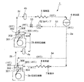
図1において、冷凍装置1は、冷媒としてNH3を用いる冷媒循環路2を備え、該冷媒循環路2に、往復動型圧縮機3と、往復動型圧縮機3の下流側に順に、油分離器4と、凝縮器5と、受液器6と、膨張弁7と、蒸発器8とが介設されて、冷凍サイクルを構成している。
(Embodiment 1)
1st Embodiment which applied this invention to the freezing apparatus is described based on FIGS. FIG. 1 is a system diagram of a refrigeration apparatus according to this embodiment.
In FIG. 1, the refrigeration apparatus 1 includes a
往復動型圧縮機3は、シリンダ301と吐出弁302を介して連通する吐出室303と、シリンダ301と吸入弁304を介して連通する吸入室305とを備えている。吐出室303は、吐出弁302のすぐ出口側に設けられ、冷媒循環路2に連通している。吸入室305は吸入弁304のすぐ出口側に設けられ、冷媒循環路2に連通している。シリンダ301で圧縮され高圧となった冷媒ガスは、吐出弁302から吐出室303に吐出される。
The reciprocating compressor 3 includes a
吐出室303から冷媒循環路2に吐出された冷媒ガスは、油分離器4で潤滑油を分離された後、凝縮器5で放熱し凝縮する。凝縮した冷媒液は、一旦受液器6に貯留される。受液器6から出た冷媒液は、膨張弁7で減圧され、蒸発器8で蒸発する。蒸発器8では負荷から蒸発潜熱を吸収する。その後、冷媒ガスは往復動圧縮機2の吸入室305に吸入され、さらに吸入弁304を介してシリンダ301に吸入される。図1中の各部位に記入された温度は、その部位での冷媒(NH3)の温度を示す。
The refrigerant gas discharged from the
本実施形態では、受液器6の下流側で冷媒液を冷媒循環路2から分岐する分岐路9が設けられている。分岐路9は吐出室303の内壁に設けられた噴射ノズル306に接続されている。分岐路9には液ポンプ11と液ポンプ11の下流側に圧力調整弁12が介設されている。冷媒液の一部は分岐路9を通り、液ポンプ11の回転数制御及び圧力調整弁12で圧力調整され、吐出室303より高圧となって、噴射ノズル306から吐出室303の内部に噴霧される。吐出室303内に噴射された冷媒液は、吐出室303内の冷媒ガスから蒸発潜熱を吸収して蒸発する。
In the present embodiment, a
これによって、吐出室303内の温度を低下させるため、吐出室303から吸入室305への伝熱を抑制できる。従って、シリンダ301に吸入される前の冷媒ガスの昇温を抑制できる。
Thereby, since the temperature in the
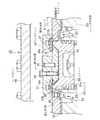
図2及び図3は、往復動型圧縮機3のシリンダ上部組立体20の具体的な構造例を示す。本実施形態の往復動型圧縮機3は、2個のシリンダが組みになっている。
図2において、シリンダ21の内部にピストン22が摺動自在に配置されている。シリンダ21はシリンダ外包体23に装着されている。シリンダ外包体23の上部にはバルブプレート31が配置され、バルブプレート31の開口31aは、シリンダ21の上部開口に合わせて配置されている。バルブプレート31に空洞部が穿設され、該空洞部にリング形をなす板状の吸入弁25とその上方に筍スプリング26が収納されている。
2 and 3 show a specific structural example of the cylinder
In FIG. 2, a piston 22 is slidably disposed inside a cylinder 21. The cylinder 21 is attached to a cylinder
筍スプリング26の弾性力が吸入弁25をシリンダ21の上端に設けられた弁座27に押し付けるように作用している。吸入弁25の下方には吸入室24が設けられ、吸入室24は、吸入弁25に作用している筍スプリング26の弾性力に抗して冷媒ガスにより吸入弁25を押し上げることにより、シリンダ21の内部と連通する。
The elastic force of the
バルブプレート31の上部に円板形状をなすバルブケージ32を設けてバルブプレート31の開口31aを遮蔽している。バルブケージ32の下面には、ボルト33により截頭円錐形の弁プレート34が結合されている。弁プレート34のバルブケージ32に対する位置決めは、位置合わせ棒35を両者の位置決め孔に通すことによって行なわれる。弁プレート34の形状はピストン22の頭部形状に嵌合し、ピストン22がシリンダ21の上端に達した時に、シリンダ21内に空間ができないようにしている。
A disc
バルブケージ32には吐出ガス通路36aが穿設されるとともに、吐出ガス通路36aに筍スプリング37が装着され、筍スプリング37の下方に、リング形をなす板状の吐出弁38が装着されている。吐出弁38の下方には、弁プレート34の周縁部に形成された弁座34aと、バルブプレート31と一体の弁座31bが配置されている。シリンダ21の吐出ガス圧が小さい時に、吐出弁38は、筍スプリング37の弾性力によって弁座34a及び31bに押し付けられて、吐出ガス通路36aを遮断している。ピストン22が上昇してシリンダ21の吐出ガス圧が大きくなると、吐出ガスが吐出弁38を押し上げて吐出ガス通路36aを開放する。
The
シリンダ外包体23とバルブプレート31の間には、断熱材からなる板状の断熱性ガスケット39が介装されている。バルブケージ32の上方には、ヘッドカバー40が配置され、バルブケージ32の上方に吐出室36を形成している。吐出室36は吐出ガス通路36aに連通すると共に、シリンダ21から吐出した高圧の吐出ガスを冷媒循環路2に送る。ヘッドカバー40に穿設された貫通孔40aには分岐管路9が接続され、ヘッドカバー内壁の開口には噴射ノズル306が取り付けられている。これによって、分岐管路9内の冷媒液が吐出室36に噴霧される。
A plate-like
図3に示すように、ヘッドカバー40の周縁部にはボルト座41が設けられるとともに、ボルト座41、バルブプレート31、断熱性ガスケット39及びシリンダ外包体23の周縁部にはボルト孔42〜45が穿設され、これらの部材をボルト孔42〜45を介して図示しないボルトによって一体に結合している。
As shown in FIG. 3, a
なお、本実施形態では、シリンダ外包体23は2個のシリンダ21を内包するものである。そのため、シリンダ外包体23には2個のシリンダ21が嵌合される2個の開口23aが穿設されている。そして、2個の開口23aの間には凹部46が設けられており、この凹部46が断熱性ガスケット39との間に断熱空間iを形成している。
In the present embodiment, the cylinder
図2及び図3の往復動型圧縮機3は、ピストン22が下降した時にシリンダ21内に低圧が形成され、これによって、吸入ガスg1が筍スプリング26の弾性力に抗して吸入弁25を押し上げ、シリンダ21内に導入される。次に、ピストン22が上昇してシリンダ21内を高圧にすると、高圧の吐出ガスg2が筍スプリング37の弾性力に抗して吐出弁38を押し上げ、吐出ガス通路36aを経て吐出室36に排出される。
2 and the reciprocating compressor of FIG. 3. 3, the piston 22 low pressure is formed in the cylinder 21 when the lowered, thereby, the intake valve intake gas g 1 is against the elastic force of the
往復動型圧縮機2が冷凍装置1に組み込まれた場合、例えば、吸入室24の温度は−20〜0℃、吸入圧は0.2〜0.4MPaであり、吐出室36の温度は120〜140℃、吐出圧は1.3〜1.6MPaである。
When the
シリンダ上部組立体20は、高温となった吐出ガスg2により加熱されるが、本実施形態では、分岐管路9から吐出室36内に冷媒液が噴射ノズル306を介して噴霧され、噴霧された冷媒液が吐出ガスから蒸発潜熱を吸収して吐出ガスを冷却すると共に、バルブプレート31とシリンダ外包体23との間に断熱性ガスケット39を介装しているので、吐出ガスg2の熱がシリンダ外包体23まで伝達して吸入室24を流れる吸入ガスg1を加熱するのを効率的に抑制できる。
The cylinder
従って、シリンダ21内に吸入される前の吸入ガスg1の昇温を抑制することができるので、吸入ガスg1の体積膨張を抑制できる。例えば、図1に示すように、噴射ノズル306に35℃の冷媒液を噴射することで、吐出室303内の吐出ガス温度を50℃に抑制でき、吸入室305内の吸入ガス温度を−10℃に抑制できる。そのため、シリンダ21内に吸入される冷媒ガスの体積膨張を防止でき、往復動型圧縮機3の体積効率の低下を抑制することができる。これによって、往復動型圧縮機3が組み込まれた冷凍装置1の冷凍能力の低下を抑制することができる。
Accordingly, it is possible to suppress the Atsushi Nobori of the suction gas g 1 before being sucked into the cylinder 21, it can be suppressed volume expansion of the intake gas g 1. For example, as shown in FIG. 1, by jetting a 35 ° C. refrigerant liquid to the
特に、冷媒として用いているNH3は比熱比が大きく、温度上昇により体積膨張が著しいので、往復動型圧縮機の体積効率の低下が大きくなる。しかし、本発明により、往復動型圧縮機3の体積効率の低下を抑え、冷凍装置1の冷凍能力を維持させることができる。
また、本実施形態では、冷媒液の蒸発潜熱と断熱性ガスケット19によって吸入ガスの温度上昇を抑えており、冷却水等を必要としないので、砂漠地帯でも適用可能であり、しかも環境汚染を生じない利点がある。
In particular, NH 3 used as a refrigerant has a large specific heat ratio, and volume expansion is remarkable due to temperature rise, so that the volume efficiency of the reciprocating compressor is greatly reduced. However, according to the present invention, a decrease in volumetric efficiency of the reciprocating compressor 3 can be suppressed, and the refrigeration capacity of the refrigeration apparatus 1 can be maintained.
Further, in this embodiment, the temperature rise of the suction gas is suppressed by the latent heat of vaporization of the refrigerant liquid and the heat insulating gasket 19 and no cooling water is required, so that it can be applied even in desert areas and causes environmental pollution. There are no advantages.
本実施形態において、冷媒液を噴射ノズル306により吐出室36に微細粒として噴霧しているので、吐出ガスからの蒸発潜熱の吸収効果を向上できる。また、断熱性ガスケット39は、吸入室24からシリンダ外包体23の周縁部まで延設されているので、断熱性ガスケット39が配設された広い領域で吐出ガス熱を遮断している。従って、吐出ガス熱がシリンダ外包体23側まで伝達するのを有効に遮断できる。
加えて、シリンダ外包体23で複数のシリンダ21の間に断熱空間iを設けているので、さらに断熱効果を向上させることができる。
In the present embodiment, since the refrigerant liquid is sprayed as fine particles in the
In addition, since the heat insulating space i is provided between the plurality of cylinders 21 in the cylinder
(実施形態2)
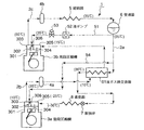
次に、本発明の冷凍装置に係る第2実施形態を図4に基づいて説明する。図4において、本実施形態の冷凍装置は、往復動圧縮機が低段圧縮機3aと高段圧縮機3bとからなる2段圧縮機で構成されている。低段圧縮機3a及び高段圧縮機3bのシリンダ上部組立体の構成は、図2及び図3に示す前記第1実施形態の構成と同一である。
受液器6から出た冷媒液は冷媒循環路2aを通って膨張弁7に至る。膨張弁7で減圧された冷媒液は、蒸発器8で負荷から蒸発潜熱を奪って蒸発し、蒸発した冷媒ガスは、低段圧縮機3aの吸入室305に吸入される。吸入室305に吸入された冷媒ガスは、吸入弁304を介してシリンダ301に吸入され、シリンダ301で圧縮される。
(Embodiment 2)
Next, 2nd Embodiment which concerns on the freezing apparatus of this invention is described based on FIG. In FIG. 4, the refrigerating apparatus of the present embodiment is constituted by a two-stage compressor in which a reciprocating compressor is composed of a low-stage compressor 3a and a high-
The refrigerant liquid from the
シリンダ301で圧縮された冷媒ガスは、吐出弁302を経て吐出室303に到り、吐出室303から冷媒循環路2bに吐出される。冷媒循環路2bに吐出された冷媒ガスは、油分離器4aで潤滑油を分離された後、高段圧縮機3bの吸入室305に吸入される。
高段圧縮機3bの吸入室305に吸入された冷媒ガスは、高段圧縮機3bのシリンダ301内で圧縮され、吐出室303から冷媒循環路2cに吐出される。冷媒循環路2cに吐出された冷媒ガスは、油分離器4bで潤滑油を分離された後、凝縮器5で放熱して凝縮する。
The refrigerant gas compressed by the
The refrigerant gas sucked into the suction chamber 305 of the
本実施形態では、受液器6の下流側で冷媒循環路2aから分岐する分岐路51を設けている。分岐路51には液ポンプ52及び圧力調整弁53が介設されている。分岐路51の末端は高段圧縮機3bの吐出室303に接続されている。冷媒液は、液ポンプ53の回転数制御及び圧力調整弁53の圧力制御により、高段圧縮機3bの吐出室303より高い圧力に加圧され、吐出室303内で噴射ノズル306から噴霧される。
In the present embodiment, a
分岐路51より下流側の冷媒循環路2aから分岐路54が分岐され、分岐路54は低段圧縮機3aの吐出室303の内壁面に設けられた噴射ノズル306に接続されている。低段圧縮機3aの吐出室303内は、分岐路54より低圧であるので、冷媒液を増圧させる必要がなく、そのまま吐出室303内に供給できる。
A
本実施形態では、分岐路51及び54から高段圧縮機3b及び低段圧縮機3aの吐出室303に冷媒液を噴霧し、該冷媒液を吐出室303内の吐出ガスの保有熱で蒸発させ、吐出ガスから蒸発潜熱を奪って吐出ガスを冷却する。従って、低段圧縮機3a及び高段圧縮機3bにおいて、吐出室303から吸入室305への熱伝達を抑えることができる。
また、図2及び図3に示すように、低段圧縮機3a及び高段圧縮機3bのシリンダヘッド20には、バルブプレート31とシリンダ外包体23との間に断熱性ガスケット39を介装しているので、断熱性ガスケット39によって吐出室36から吸入室24への熱伝達を抑制できる。
In the present embodiment, the refrigerant liquid is sprayed from the
As shown in FIGS. 2 and 3, the cylinder heads 20 of the low-stage compressor 3a and the high-
図4に示すように、低段圧縮機3aの吸入室305の温度を−25℃に抑え、高段圧縮機3bの吸入室305の温度を15℃に抑えることができるので、往復動型圧縮機の体積効率の低下を抑え、冷凍装置1の冷凍能力を維持できる。
As shown in FIG. 4, since the temperature of the suction chamber 305 of the low stage compressor 3a can be suppressed to −25 ° C. and the temperature of the suction chamber 305 of the
なお、高段圧縮機3bの吐出室303と分岐路51の圧力は同一であるので、冷媒液を分岐路51から高段圧縮機3bの吐出室303に供給する場合には、液ポンプ52及び圧力調整弁53で増圧する必要がある。一方、低段圧縮機3aの吐出室303は分岐路54より低圧であるので、冷媒液を分岐路54から低段圧縮機3aの吐出室303に供給する場合に増圧する必要はない。従って、増圧機が不要であり、動力低減を可能とする。
Since the pressure in the
低段圧縮機3aの吸入ガス温度は、高段圧縮機3bの吸入ガス温度と比べて低い。例えば、低段圧縮機3aの吸入ガス温度は−30℃であり、高段圧縮機側と比べて吐出ガスとの温度差が大きい。従って、吐出ガスからの熱伝達による吸入ガスの温度上昇の影響は、低段圧縮機3aのほうが受けやすい。そのため、少なくとも低段圧縮機3aの吐出室303に分岐路54から冷媒液を供給するようにすれば、吸入ガスの温度抑制効果をより大きくし、冷凍能力の低下をより抑えることができる。
The intake gas temperature of the low stage compressor 3a is lower than the intake gas temperature of the
(実施形態3)
次に本発明に係る冷凍装置の第3実施形態を図5に基づいて説明する。図5において、本実施形態では、受液器6の下流側で冷媒循環路2aに液ガス熱交換器61を介在させ、液ガス熱交換器61に油分離器4aの下流側の冷媒循環路2bを接続している。そして、受液器6から出た冷媒液と油分離器4aの下流側の吐出冷媒ガスとを液ガス熱交換器61で熱交換させ、該吐出冷媒ガスによって該冷媒液を冷却するようにしている。その他の構成は、図4に示す前記第2実施形態と同一である。同一構成の部材又は機器には、第2実施形態と同一の符号を付しており、それらの説明を省略する。
(Embodiment 3)
Next, a third embodiment of the refrigeration apparatus according to the present invention will be described with reference to FIG. 5, in the present embodiment, a liquid gas heat exchanger 61 is interposed in the
低段圧縮機3aの吐出室303には、分岐路54を介して受液器6の下流側の冷媒液を供給し、該冷媒液を図2に示すように、噴射ノズル306を介して吐出室303に噴霧している。そして、該冷媒液を蒸発させて吐出室303内の吐出ガスの温度を低下させている。例えば、凝縮温度が35℃で、蒸発温度が−30℃の場合、凝縮器5及び受液器6内の冷媒液の温度は35℃であり、この冷媒液を吐出室303内で蒸発させ、蒸発潜熱を吸収することにより、吐出室303内の吐出ガス温度を10℃に冷却できる。
The refrigerant liquid on the downstream side of the
この10℃の吐出ガスを液ガス熱交換器61に導入し、液ガス熱交換器61で受液器6から出た35℃の冷媒液を30℃に冷却することができる。
The discharged gas at 10 ° C. is introduced into the liquid gas heat exchanger 61, and the 35 ° C. refrigerant liquid discharged from the
このように、本実施形態によれば、前記第2実施形態と同様の作用効果を得ることができるほか、液ガス熱交換器61において、低段圧縮機3aの吐出ガスで受液器6出口側の冷媒液を冷却するようにしているので、冷凍装置1の冷凍能力をさらに向上させ、COPを向上させることができる。
As described above, according to the present embodiment, the same operational effects as those of the second embodiment can be obtained, and in the liquid gas heat exchanger 61, the outlet of the
(実施形態4)
次に本発明の冷凍装置に係る第4実施形態を図6に基づいて説明する。図6において、本実施形態では、液ガス熱交換器61の下流側で冷媒循環路2aから分岐路71を分岐させ、分岐路71を低段圧縮機3aの吐出室303に接続している。その他の構成は、前記第3実施形態と同一であるので、同一の部材又は機器の説明を省略する。
分岐路71の末端は低段圧縮機3aの吐出室303内に配設された噴射ノズル306に接続されており、吐出室303の構成も前記第1〜第3実施形態と同一である。
(Embodiment 4)
Next, 4th Embodiment which concerns on the freezing apparatus of this invention is described based on FIG. In FIG. 6, in this embodiment, the
The end of the
本実施形態によれば、低段圧縮機3a及び高段圧縮機3bの吐出室303における吐出ガスの冷却効果に加えて、液ガス熱交換器61で過冷却された後の低温度(30℃)の冷媒液を分岐路71を介して低段圧縮機32aの吐出室303に供給しているので、該吐出室303の吐出ガスの冷却効果をさらに向上できる。そのため、分岐路71に供給する冷媒液量を少なくできるので、噴射ノズル306を小型化できる利点がある。
According to this embodiment, in addition to the cooling effect of the discharge gas in the
(実施形態5)
次に、本発明の冷凍装置に係る第5実施形態を図7に基づいて説明する。本実施形態は、図6に示す前記第4実施形態の液ガス熱交換器71を中間冷却器81に置き換えたものであり、その他の構成は第4実施形態と同一である。中間冷却器81では、中間冷却器81の上流側で冷媒循環路2aから分岐する分岐路82を設け、分岐路82に膨張弁83を介設している。
(Embodiment 5)
Next, 5th Embodiment which concerns on the freezing apparatus of this invention is described based on FIG. In the present embodiment, the liquid
本実施形態の中間冷却器81は、中間冷却器81の内部に冷媒循環路2aに連通した管路81aが配設され、管路81aの外側に低段圧縮機3aの吐出冷媒ガスが充満する空間が形成される。そして、管路81a内を流れる冷媒液と吐出冷媒ガスとは、管路81aの管壁を通して熱交換される。
In the intermediate cooler 81 of this embodiment, a
かかる構成において、分岐路82に流入した冷媒液は膨張弁83を通って減圧された後、中間冷却器81に流入する。該冷媒液は中間冷却器81内で蒸発し蒸発潜熱を奪うので、冷媒循環路2aから中間冷却器81の管路81aに流入した冷媒液の冷却効果を増すことができる。中間冷却器81で冷媒液は、例えば25℃に冷却される。
In this configuration, the refrigerant liquid that has flowed into the
従って、本実施形態によれば、前記第4実施形態と比べて、中間冷却器81による冷媒液の冷却効果を高めることができるので、中間冷却器81の出口側の熱媒液の温度をさらに低減できる。そのため、分岐路71から低段圧縮機3aの吐出室303に供給される冷媒液の温度をさらに低下できるので、低段圧縮機3aの吐出ガスの温度抑制効果を第4実施形態と比べてさらに向上できる。また、膨張弁7に流入する冷媒液の冷却効果も向上するため、冷凍装置1の冷凍能力をさらに向上できる。
Therefore, according to this embodiment, compared with the said 4th Embodiment, since the cooling effect of the refrigerant | coolant liquid by the intermediate cooler 81 can be heightened, the temperature of the heat transfer fluid at the exit side of the intermediate cooler 81 is further increased. Can be reduced. Therefore, since the temperature of the refrigerant liquid supplied from the
(実施形態6)
次に、本発明の冷凍装置に係る第6実施形態を図8に基づいて説明する。本実施形態は、図5に示す第3実施形態と比べて、第3実施形態の液ガス熱交換器61を中間冷却器91と置き換えたものである。そして、中間冷却器91の上流側の冷媒循環路2aに膨張弁92を介設している。その他の構成は第3実施形態と同一である。
(Embodiment 6)
Next, 6th Embodiment which concerns on the freezing apparatus of this invention is described based on FIG. In the present embodiment, the liquid gas heat exchanger 61 of the third embodiment is replaced with an intermediate cooler 91 as compared with the third embodiment shown in FIG. An
かかる構成により、冷媒循環路2aの冷媒液は膨張弁92を通って減圧され、中間冷却器91の内部で低段圧縮機3aの吐出ガスから蒸発潜熱を奪って蒸発する。なお、本実施形態の中間冷却器91は、内部空間が形成された密閉容器形状をなし、内部空間で冷媒液と吐出ガスとが接触熱交換を行なう方式のものである。
With this configuration, the refrigerant liquid in the
本実施形態によれば、第3実施形態と比べて、液ガス熱交換器61の代わりに中間冷却器91を配設しているため、膨張弁7に至る冷媒液の冷却効果をさらに向上できると共に(例えば1℃に冷却可能)、高段圧縮機3bの吸入室305に供給される冷媒ガスの冷却効果も向上できる(例えば6℃に冷却可能)。
また、図7に示す第5実施形態と比べて、中間冷却器91の内部に配設される伝熱管が不要となり、設備コストを低減することができる。
According to this embodiment, since the
Moreover, compared with 5th Embodiment shown in FIG. 7, the heat exchanger tube arrange | positioned inside the
(実施形態7)
次に、本発明の冷凍装置に係る第7実施形態を図9に基づいて説明する。図9は、本発明の冷凍装置に組み込まれた往復動型圧縮機のシリンダ上部組立体100を示す。本実施形態の往復動型圧縮機は、2個のシリンダが対になって構成されている。
図9において、シリンダ101の内部にピストン102が摺動自在に配置されている。シリンダ101はシリンダ外包体103に装着されている。シリンダ外包体103の上部にはバルブプレート111が配置され、バルブプレート111の開口111aが、シリンダ101の上部開口と同心上に配置されている。バルブプレート111に空洞部が穿設され、該空洞部にリング形をなす板状の吸入弁105とその上方に筍スプリング106が収納されている。
(Embodiment 7)
Next, 7th Embodiment which concerns on the freezing apparatus of this invention is described based on FIG. FIG. 9 shows a cylinder upper assembly 100 of a reciprocating compressor incorporated in the refrigeration apparatus of the present invention. The reciprocating compressor of the present embodiment is configured with two cylinders in pairs.
In FIG. 9, a
筍スプリング106の弾性力が吸入弁105をシリンダ101の上端に押し付けるように作用している。吸入弁105の下方には吸入ガス通路104a及び吸入ガス通路104aに連通した吸入室104が設けられている。ピストン102がシリンダ101内を下降した時、シリンダ101内は低圧となり、吸入室104との間で差圧を生じる。この時冷媒ガスg1が吸入弁105を押し上げて、シリンダ101内に吸入される。
The elastic force of the
バルブプレート111の上部に円板形状をなすバルブケージ112を取り付けて、バルブプレート111の開口111aを遮蔽している。バルブケージ112の下面には、ボルト113により截頭円錐形の弁プレート114が結合されている。
バルブケージ112には吐出ガス通路116aが穿設されるとともに、バルブケージ112に筍スプリング117が装着され、筍スプリング117の下方に、吐出ガス通路116aに面してリング形をなす板状の吐出弁118が装着されている。
ピストン102が上昇してシリンダ101の吐出ガス圧が大きくなると、吐出ガスg2が吐出弁118を押し上げて吐出ガス通路116aに吐出する。
A disc
A
When the
バルブケージ112の上方は、ヘッドカバー121で覆われ、バルブケージ112の上方に吐出室116を形成している。吐出室116は吐出ガス通路116aに連通すると共に、シリンダ101から吐出した高圧の吐出ガスを冷媒循環路に送る。
吐出ガス通路116aから吐出室116に吐出された冷媒ガスg2は、シリンダ外包体103に形成された通路107を通って、冷媒循環路に送られる。通路107は、吸入室104及び吸入ガス通路104aとシリンダ外包体103の隔壁を隔てて隣接配置されている。
An upper portion of the
The refrigerant gas g 2 discharged from the
図9に示すように、ヘッドカバー121及びシリンダ外包体103には、夫々貫通孔121a及び121bが設けられ、該貫通孔には、夫々図1の分岐管路9に相当する分岐管路122a及び122bが接続されている。貫通孔121aはヘッドカバー内壁に開口し、貫通孔121bは通路107に開口している。そして、これら開口に夫々噴射ノズル123a及び123bが取り付けられている。これによって、図示しない受液器から凝縮した冷媒液が、分岐管路122a及び122bを通って吐出室116及び通路107に噴霧される。
ヘッドカバー121の表面には冷却水ジャケット124で被覆されて密閉された冷却水充填空間125を形成している。冷却水ジャケット124に冷却水供給孔124aが設けられ、冷却水供給孔124aから冷却水wが充填される。
As shown in FIG. 9, the head cover 121 and the cylinder
A cooling
本実施形態によれば、冷媒液を噴射ノズル123a、123bにより吐出室116及び通路107に微細粒として噴霧しているので、吐出ガスからの蒸発潜熱の吸収効果を向上できる。
通路107は吸入室104及び吸入ガス通路104aとシリンダ外包体103の隔壁を隔てて隣接配置されているが、通路107に噴射ノズル123bで冷媒液を噴霧し、吐出ガスの温度上昇を抑えているので、通路107を通る冷媒ガスによって吸入室104及び吸入ガス通路104aを通る吸入ガスが加温するのを抑えることができる。
According to the present embodiment, since the refrigerant liquid is sprayed as fine particles in the
The
(実施形態8)
本発明の冷凍装置に係る第8実施形態を図10に基づいて説明する。図10において、
本実施形態は、図1〜図3に示す前記第1実施形態と比べて、冷凍装置1の受液器6の下流側で冷媒液を分岐する分岐路9をなくすと共に、単段の往復動型圧縮機3の吐出室303内では、分岐管路9を接続しておらず、かつ噴射ノズル306を装着していない。その他の構成は第1実施形態と同一である。
(Embodiment 8)
An eighth embodiment according to the refrigeration apparatus of the present invention will be described with reference to FIG. In FIG.
Compared with the first embodiment shown in FIGS. 1 to 3, this embodiment eliminates the
本実施形態では、凝縮した冷媒液の蒸発潜熱を利用した吐出室36内の吐出ガスの冷却を行なっていない。そして、吸入室36と吐出室24間の熱伝達をバルブプレート31とシリンダ外包体23との間に介装した断熱性ガスケット39で遮断するようにして、吸入室24の吸入ガスの昇温を抑制している。また、図3に示すように、複数のシリンダ21間でシリンダ外包体23に断熱空間iを設けることで、断熱効果を増すようにしている。
これによって、シリンダ21に吸入される前の吸入ガスの昇温を抑えることができるので、往復動型圧縮機の体積効率の低下を抑え、冷凍装置1の冷凍能力を維持できる。
In the present embodiment, the discharge gas in the
As a result, the temperature rise of the intake gas before being sucked into the cylinder 21 can be suppressed, so that a decrease in volume efficiency of the reciprocating compressor can be suppressed and the refrigeration capacity of the refrigeration apparatus 1 can be maintained.
本発明によれば、往復動型圧縮機内部での吸入冷媒ガスの温度上昇を抑制することによって、高密度の冷媒ガスを吸入できるので、体積効率を向上でき、それによって、往復動型圧縮機が組み込まれた冷凍装置等のヒートポンプ装置の能力を向上させることができる。 According to the present invention, since the high-density refrigerant gas can be sucked by suppressing the rise in the temperature of the sucked refrigerant gas inside the reciprocating compressor, the volumetric efficiency can be improved, thereby the reciprocating compressor. It is possible to improve the capacity of a heat pump device such as a refrigeration device in which is incorporated.
1 冷凍装置
2、2a、2b、2c 冷媒循環路
3 往復動型圧縮機
3a 低段圧縮機
3b 高段圧縮機
5 凝縮器
7 膨張弁
8 蒸発器
9、54 分岐路(冷媒液戻し流路)
20、100 シリンダ上部組立体
21、101、301 シリンダ
22、102 ピストン
23、103 シリンダ外包体
24、104、305 吸入室
25、105、304 吸入弁
31、111 バルブプレート
32、112 バルブケージ(遮蔽板)
36、116、303 吐出室
36a、116a 吐出ガス通路
38、118、302 吐出弁
39 断熱性ガスケット
40 ヘッドカバー
40a 貫通孔(冷媒液供給口)
51 分岐路(第2の熱媒液戻し流路)
61 液ガス熱交換器(冷媒液熱交換器)
81、91 中間冷却器
306 噴射ノズル
i 断熱空間
DESCRIPTION OF SYMBOLS 1
20, 100 Cylinder
36, 116, 303
51 branch path (second heat medium liquid return flow path)
61 Liquid gas heat exchanger (refrigerant liquid heat exchanger)
81, 91 Intermediate cooler 306 Injection nozzle i Thermal insulation space
Claims (14)
凝縮器で凝縮した冷媒液の一部を往復動型圧縮機のシリンダ上部組立体に設けられた吐出室又は該吐出室に連通した吐出空間に戻す冷媒液戻し流路を設け、
該冷媒液戻し流路を介して該吐出室又は吐出空間に冷媒液の一部を供給し、冷媒液の蒸発潜熱により該吐出室又は吐出空間を冷却するように構成したことを特徴とするヒートポンプ装置。 In a heat pump device comprising a heat pump cycle in which a reciprocating compressor, a condenser, an expansion valve and an evaporator are interposed in a refrigerant circuit,
A refrigerant liquid return passage is provided for returning a part of the refrigerant liquid condensed by the condenser to a discharge chamber provided in the cylinder upper assembly of the reciprocating compressor or a discharge space communicating with the discharge chamber,
A heat pump configured to supply a part of the refrigerant liquid to the discharge chamber or the discharge space through the refrigerant liquid return flow path, and to cool the discharge chamber or the discharge space by the latent heat of vaporization of the refrigerant liquid. apparatus.
該冷媒液戻し流路を介して低段圧縮機の該吐出室又は吐出空間に冷媒液の一部を供給するように構成したことを特徴とする請求項1又は2に記載のヒートポンプ装置。 The reciprocating compressor is composed of a low-stage compressor and a high-stage compressor, and a part of the refrigerant liquid discharged from the high-stage compressor and condensed in the condenser is communicated with the discharge chamber of the low-stage compressor or the discharge chamber. Providing a refrigerant liquid return flow path to return to the discharged discharge space,
3. The heat pump device according to claim 1, wherein a part of the refrigerant liquid is supplied to the discharge chamber or the discharge space of the low-stage compressor through the refrigerant liquid return flow path.
第2の冷媒液戻し流路を介して高段圧縮機の該吐出室又は吐出空間に冷媒液の一部を供給するように構成したことを特徴とする請求項3に記載のヒートポンプ装置。 A second refrigerant liquid return channel is provided for returning a part of the refrigerant liquid discharged from the high stage compressor and condensed by the condenser to the discharge chamber or the discharge space of the high stage compressor, and the second refrigerant liquid return A pressure booster is installed in the flow path,
The heat pump device according to claim 3, wherein a part of the refrigerant liquid is supplied to the discharge chamber or the discharge space of the high-stage compressor through the second refrigerant liquid return flow path.
該中間冷却器で凝縮器から出た冷媒液の一部を蒸発させることにより、凝縮器から出た他の冷媒液及び低段圧縮機から吐出された冷媒ガスを冷却するように構成したことを特徴とする請求項3又は4に記載のヒートポンプ装置。 An intermediate cooler is provided in the refrigerant circuit between the condenser and the expansion valve, and the refrigerant circuit that guides the refrigerant gas discharged from the low-stage compressor to the intermediate cooler to the discharge chamber or the discharge space of the high-stage compressor Connect
The intermediate cooler is configured to evaporate a part of the refrigerant liquid exiting from the condenser, thereby cooling the other refrigerant liquid exiting from the condenser and the refrigerant gas discharged from the low-stage compressor. The heat pump device according to claim 3 or 4, characterized by the above.
吐出ガスを凝縮して得られた冷媒液の一部を受け入れる冷媒液供給口を吐出室又は該吐出室に連通した吐出空間に設け、
該冷媒液供給口を介して該吐出室又は吐出空間に冷媒液を受け入れ、冷媒液の蒸発潜熱により該吐出室又は吐出空間を冷却するように構成したことを特徴とする冷媒用往復動型圧縮機。 In a reciprocating compressor for a refrigerant comprising a suction chamber communicating with a cylinder via a suction valve and a discharge chamber communicating with the cylinder via a discharge valve in a cylinder upper assembly,
A refrigerant liquid supply port for receiving a part of the refrigerant liquid obtained by condensing the discharge gas is provided in the discharge chamber or the discharge space communicating with the discharge chamber,
Reciprocating compression for refrigerant, wherein the refrigerant liquid is received in the discharge chamber or the discharge space through the refrigerant liquid supply port, and the discharge chamber or the discharge space is cooled by latent heat of evaporation of the refrigerant liquid. Machine.
吸入室と吐出室間に断熱材を介装し、吸入室と吐出室間の伝熱を遮断するように構成したことを特徴とする冷媒用往復動型圧縮機。 In a reciprocating compressor for a refrigerant comprising a suction chamber communicating with a cylinder via a suction valve and a discharge chamber communicating with the cylinder via a discharge valve in a cylinder upper assembly,
A reciprocating compressor for refrigerant, characterized in that a heat insulating material is interposed between the suction chamber and the discharge chamber to block heat transfer between the suction chamber and the discharge chamber.
シリンダを遮蔽し吐出ガス通路を形成すると共に、該吐出ガス通路に吐出弁を設けた遮蔽板と、
該遮蔽板の上方を覆って吐出室を形成したヘッドカバーと、
該遮蔽板の下方に配置されシリンダを内包するとともに吸入弁を内蔵したバルブプレートと、
該バルブプレートの下方に配置され吸入室を形成したシリンダ外包体とで構成するとともに、
バルブプレートとシリンダ外包体との間に板状の断熱性ガスケットを介装し、
バルブプレート及び断熱性ガスケットを拡径してバルブプレート及び断熱性ガスケットの外周端縁部を前記ヘッドカバーとシリンダ外包体の接合部で両側から挟持固定したことを特徴とする請求項12に記載の冷媒用往復動型圧縮機。 Cylinder upper assembly
A shielding plate which shields the cylinder to form a discharge gas passage and is provided with a discharge valve in the discharge gas passage;
A head cover that covers the top of the shielding plate and forms a discharge chamber;
A valve plate disposed below the shielding plate and containing a cylinder and incorporating a suction valve;
And a cylinder outer casing disposed below the valve plate and forming a suction chamber,
A plate-like heat insulating gasket is interposed between the valve plate and the cylinder outer casing,
13. The refrigerant according to claim 12, wherein the diameter of the valve plate and the heat insulating gasket is expanded, and the outer peripheral edge portions of the valve plate and the heat insulating gasket are sandwiched and fixed from both sides by the joint portion between the head cover and the cylinder outer cover. Reciprocating compressor.
Priority Applications (1)
| Application Number | Priority Date | Filing Date | Title |
|---|---|---|---|
| JP2008219221A JP5486174B2 (en) | 2008-08-28 | 2008-08-28 | Heat pump device and reciprocating compressor for refrigerant |
Applications Claiming Priority (1)
| Application Number | Priority Date | Filing Date | Title |
|---|---|---|---|
| JP2008219221A JP5486174B2 (en) | 2008-08-28 | 2008-08-28 | Heat pump device and reciprocating compressor for refrigerant |
Publications (3)
| Publication Number | Publication Date |
|---|---|
| JP2010053765A true JP2010053765A (en) | 2010-03-11 |
| JP2010053765A5 JP2010053765A5 (en) | 2010-04-22 |
| JP5486174B2 JP5486174B2 (en) | 2014-05-07 |
Family
ID=42069947
Family Applications (1)
| Application Number | Title | Priority Date | Filing Date |
|---|---|---|---|
| JP2008219221A Active JP5486174B2 (en) | 2008-08-28 | 2008-08-28 | Heat pump device and reciprocating compressor for refrigerant |
Country Status (1)
| Country | Link |
|---|---|
| JP (1) | JP5486174B2 (en) |
Cited By (4)
| Publication number | Priority date | Publication date | Assignee | Title |
|---|---|---|---|---|
| WO2012144182A1 (en) * | 2011-04-20 | 2012-10-26 | 東京電力株式会社 | Condensing device |
| JP2016522388A (en) * | 2013-06-24 | 2016-07-28 | エルジー・ケム・リミテッド | Heat recovery equipment |
| WO2022050181A1 (en) | 2020-09-03 | 2022-03-10 | 株式会社前川製作所 | Compressor and compressor system |
| WO2022050180A1 (en) | 2020-09-03 | 2022-03-10 | 株式会社前川製作所 | Compressor, and compressor system |
Citations (4)
| Publication number | Priority date | Publication date | Assignee | Title |
|---|---|---|---|---|
| JPS5564075U (en) * | 1979-11-21 | 1980-05-01 | ||
| JPS58214697A (en) * | 1982-06-08 | 1983-12-13 | Ebara Corp | Centrifugal type heat pump |
| JPS61159053A (en) * | 1984-12-28 | 1986-07-18 | 株式会社荏原製作所 | Heat pump |
| JP2009539058A (en) * | 2006-06-01 | 2009-11-12 | キャリア コーポレイション | Multistage compressor unit for refrigeration system |
-
2008
- 2008-08-28 JP JP2008219221A patent/JP5486174B2/en active Active
Patent Citations (4)
| Publication number | Priority date | Publication date | Assignee | Title |
|---|---|---|---|---|
| JPS5564075U (en) * | 1979-11-21 | 1980-05-01 | ||
| JPS58214697A (en) * | 1982-06-08 | 1983-12-13 | Ebara Corp | Centrifugal type heat pump |
| JPS61159053A (en) * | 1984-12-28 | 1986-07-18 | 株式会社荏原製作所 | Heat pump |
| JP2009539058A (en) * | 2006-06-01 | 2009-11-12 | キャリア コーポレイション | Multistage compressor unit for refrigeration system |
Cited By (11)
| Publication number | Priority date | Publication date | Assignee | Title |
|---|---|---|---|---|
| WO2012144182A1 (en) * | 2011-04-20 | 2012-10-26 | 東京電力株式会社 | Condensing device |
| JP2012225582A (en) * | 2011-04-20 | 2012-11-15 | Tokyo Electric Power Co Inc:The | Condensation apparatus |
| CN103518106A (en) * | 2011-04-20 | 2014-01-15 | 东京电力株式会社 | Condensing device |
| CN103518106B (en) * | 2011-04-20 | 2016-10-05 | 东京电力株式会社 | Condensing unit |
| US9625191B2 (en) | 2011-04-20 | 2017-04-18 | Tokyo Electric Power Company, Incorporated | Condensing apparatus |
| JP2016522388A (en) * | 2013-06-24 | 2016-07-28 | エルジー・ケム・リミテッド | Heat recovery equipment |
| US9612045B2 (en) | 2013-06-24 | 2017-04-04 | Lg Chem, Ltd. | Heat recovery apparatus |
| WO2022050181A1 (en) | 2020-09-03 | 2022-03-10 | 株式会社前川製作所 | Compressor and compressor system |
| WO2022050180A1 (en) | 2020-09-03 | 2022-03-10 | 株式会社前川製作所 | Compressor, and compressor system |
| KR20230042341A (en) | 2020-09-03 | 2023-03-28 | 가부시끼가이샤 마에가와 세이사꾸쇼 | compressors and compressor systems |
| KR20230042348A (en) | 2020-09-03 | 2023-03-28 | 가부시끼가이샤 마에가와 세이사꾸쇼 | compressors and compressor systems |
Also Published As
| Publication number | Publication date |
|---|---|
| JP5486174B2 (en) | 2014-05-07 |
Similar Documents
| Publication | Publication Date | Title |
|---|---|---|
| US20110203304A1 (en) | Heat pump unit and reciprocating compressor for refrigerant | |
| US20150159919A1 (en) | Heat pump unit | |
| US7694528B2 (en) | Heat exchanging apparatus | |
| US20110232325A1 (en) | Refrigerating apparatus | |
| EP1862749A2 (en) | Vapor Compression Refrigeration Cycle | |
| JP5486174B2 (en) | Heat pump device and reciprocating compressor for refrigerant | |
| CN102003848B (en) | Refrigeration system | |
| JP5553628B2 (en) | A heat pump device comprising a reciprocating compressor | |
| KR20070116883A (en) | Refrigerating apparatus | |
| CN104676935B (en) | refrigerating circulation device | |
| CN104791251A (en) | Rotary compressor, heat pump system employing rotary compressor and air-conditioning system employing rotary compressor | |
| JP5882110B2 (en) | Regenerator type refrigerator, regenerator | |
| CN105828575B (en) | Jet flow two-phase heat exchange cold plate and cooling system for rail transit | |
| KR100886107B1 (en) | Heat exchanger | |
| WO2022050180A1 (en) | Compressor, and compressor system | |
| KR100764783B1 (en) | Reciprocating compressor and refrigerating system with this and sopercritical refrigerating system with this | |
| CN105674633A (en) | Heat regenerator with gas and liquid separating function and refrigeration air conditioner system using heat regenerator | |
| CN201155445Y (en) | Spray cooling closed type compressor | |
| CN111043795B (en) | Compressor assembly and refrigeration equipment | |
| CN103712380B (en) | Regenerator and the refrigeration system of three fluid streams heat exchange can be realized | |
| CN111765667B (en) | Compressor with heat recovery function, heat pump system and control method thereof | |
| CN210512240U (en) | Refrigeration system combined with evaporative refrigeration mode | |
| CN105332898B (en) | Piston compressor and refrigerating plant | |
| KR100371188B1 (en) | Heat exchanger for pulse tube refrigerator | |
| CN113294939A (en) | Composite fluid refrigeration equipment and fluid circulation system thereof |
Legal Events
| Date | Code | Title | Description |
|---|---|---|---|
| A521 | Request for written amendment filed |
Free format text: JAPANESE INTERMEDIATE CODE: A523 Effective date: 20100209 |
|
| A621 | Written request for application examination |
Free format text: JAPANESE INTERMEDIATE CODE: A621 Effective date: 20110802 |
|
| A977 | Report on retrieval |
Free format text: JAPANESE INTERMEDIATE CODE: A971007 Effective date: 20121114 |
|
| A131 | Notification of reasons for refusal |
Free format text: JAPANESE INTERMEDIATE CODE: A131 Effective date: 20121225 |
|
| A521 | Request for written amendment filed |
Free format text: JAPANESE INTERMEDIATE CODE: A523 Effective date: 20130225 |
|
| A131 | Notification of reasons for refusal |
Free format text: JAPANESE INTERMEDIATE CODE: A131 Effective date: 20130827 |
|
| A521 | Request for written amendment filed |
Free format text: JAPANESE INTERMEDIATE CODE: A523 Effective date: 20131028 |
|
| TRDD | Decision of grant or rejection written | ||
| A01 | Written decision to grant a patent or to grant a registration (utility model) |
Free format text: JAPANESE INTERMEDIATE CODE: A01 Effective date: 20140204 |
|
| A61 | First payment of annual fees (during grant procedure) |
Free format text: JAPANESE INTERMEDIATE CODE: A61 Effective date: 20140221 |
|
| R150 | Certificate of patent or registration of utility model |
Ref document number: 5486174 Country of ref document: JP Free format text: JAPANESE INTERMEDIATE CODE: R150 |
|
| R250 | Receipt of annual fees |
Free format text: JAPANESE INTERMEDIATE CODE: R250 |
|
| R250 | Receipt of annual fees |
Free format text: JAPANESE INTERMEDIATE CODE: R250 |
|
| R250 | Receipt of annual fees |
Free format text: JAPANESE INTERMEDIATE CODE: R250 |
|
| R250 | Receipt of annual fees |
Free format text: JAPANESE INTERMEDIATE CODE: R250 |
|
| R250 | Receipt of annual fees |
Free format text: JAPANESE INTERMEDIATE CODE: R250 |
|
| R250 | Receipt of annual fees |
Free format text: JAPANESE INTERMEDIATE CODE: R250 |