JP2010053745A - Gas turbine exhaust temperature detection device - Google Patents
Gas turbine exhaust temperature detection device Download PDFInfo
- Publication number
- JP2010053745A JP2010053745A JP2008218449A JP2008218449A JP2010053745A JP 2010053745 A JP2010053745 A JP 2010053745A JP 2008218449 A JP2008218449 A JP 2008218449A JP 2008218449 A JP2008218449 A JP 2008218449A JP 2010053745 A JP2010053745 A JP 2010053745A
- Authority
- JP
- Japan
- Prior art keywords
- gas turbine
- exhaust gas
- temperature detection
- strut
- gas
- Prior art date
- Legal status (The legal status is an assumption and is not a legal conclusion. Google has not performed a legal analysis and makes no representation as to the accuracy of the status listed.)
- Pending
Links
Images


Landscapes
- Measuring Temperature Or Quantity Of Heat (AREA)
Abstract
Description
本発明は、ガスタービン排気温度検出装置に関するものである。 The present invention relates to a gas turbine exhaust temperature detection device.
従来、ガスタービン排気温度検出装置として、中実の金属製のストラットに設けられたガス取り入れ穴に熱電対を挿入し、取り入れ穴内に流れ込むガスの温度を検出するものが知られている。しかし、この装置では、ガスタービンエンジン性能の悪化を抑制するため、ガス取り入れ穴を小さくしている。このため、熱電対により検出される排気温度は、ストラット自体の温度に影響され易い。すなわち、ストラット自体の温度が金属の熱伝達によって排気温度よりも低いので、熱電対によって検出される温度は、実際のガス温度よりも低い。その結果、排気温度の検出精度の向上を図り難い。 2. Description of the Related Art Conventionally, as a gas turbine exhaust temperature detecting device, a device that detects a temperature of a gas flowing into an intake hole by inserting a thermocouple into a gas intake hole provided in a solid metal strut is known. However, in this apparatus, the gas intake hole is made small in order to suppress the deterioration of the gas turbine engine performance. For this reason, the exhaust temperature detected by the thermocouple is easily affected by the temperature of the strut itself. That is, the temperature detected by the thermocouple is lower than the actual gas temperature because the temperature of the strut itself is lower than the exhaust temperature due to heat transfer of the metal. As a result, it is difficult to improve the detection accuracy of the exhaust temperature.
上記の問題を解決するために、様々な試みが行われている。例えば特表2007−515644号公報に記載されるように、熱電対を支持する支持部材であって、その内部に設けられた空洞、排気ガスを空洞内に導入するための一連の孔、及び空洞内のガスを外部に排出する開口を備えるものが知られている。この検出装置は、支持部材の開口に熱電対を挿入し、空洞で混合され開口を通過するガスの温度を検出することにより、排気温度の検出精度の向上を図ろうとするものである。
しかしながら、上述したガスタービン排気温度検出装置にあっては、排気ガスを支持部材の空洞内に導入する孔が複数であるため、排気ガスによる抵抗が大きくなり、ガスタービンエンジン性能を悪化させる問題があった。 However, in the gas turbine exhaust temperature detecting device described above, since there are a plurality of holes through which the exhaust gas is introduced into the cavity of the support member, there is a problem that resistance due to the exhaust gas increases and the performance of the gas turbine engine deteriorates. there were.
そこで本発明は、このような技術課題を解決するためになされたものであって、排気温度の検出精度の向上を図りつつ、エンジン性能の低下を軽減することができるガスタービン排気温度検出装置を提供することを目的とする。 Accordingly, the present invention has been made to solve such a technical problem, and provides a gas turbine exhaust temperature detection device capable of reducing deterioration in engine performance while improving exhaust temperature detection accuracy. The purpose is to provide.
すなわち本発明に係るガスタービン排気温度検出装置は、外周ケーシングと内周ケーシングとを連結するストラットに排気温度検出手段が取り付けられ、ガスタービンの排気ガスの温度を検出するガスタービン排気温度検出装置において、ストラットの内部には、ガスタービンの動翼の先端と外周ケーシングとの隙間を流れるチップクリアランス流れを排気ガスの上流側から下流側にかけて通すための排気ガス流通路が設けられていることを特徴とする。 That is, in the gas turbine exhaust temperature detecting device according to the present invention, an exhaust temperature detecting means is attached to a strut connecting the outer casing and the inner casing, and the temperature of the exhaust gas of the gas turbine is detected. The exhaust gas flow passage is provided in the strut to allow the tip clearance flow that flows through the gap between the tip of the moving blade of the gas turbine and the outer casing from the upstream side to the downstream side of the exhaust gas. And
この発明によれば、ストラットの内部には、チップクリアランス流れを排気ガスの上流側から下流側にかけて通すための排気ガス流通路が設けられているので、この排気ガス流通路に流れるチップクリアランス流れは、ストラットの内部からストラットを温め、ストラットの温度を内部から上昇させることができる。このため、より正確な排気ガス温度検出が可能となり、排気温度の検出精度の向上を図ることができる。また、このようにチップクリアランス流れを利用することにより、ストラットの温度を内部から確実に上昇させると共に、エンジン性能の低下を軽減することが可能となる。 According to the present invention, the exhaust gas flow passage for passing the tip clearance flow from the upstream side to the downstream side of the exhaust gas is provided inside the strut. Therefore, the tip clearance flow flowing through the exhaust gas flow passage is The strut can be warmed from the inside of the strut, and the temperature of the strut can be raised from the inside. For this reason, more accurate exhaust gas temperature detection becomes possible, and the detection accuracy of exhaust gas temperature can be improved. In addition, by using the tip clearance flow in this way, it is possible to reliably raise the temperature of the strut from the inside and reduce the deterioration of the engine performance.
本発明に係るガスタービン排気温度検出装置において、排気ガス流通路は、外周ケーシングの近傍に設けられチップクリアランス流れを排気ガスの上流側から排気ガス流通路の内部に導入するための導入孔を備えることが好適である。 In the gas turbine exhaust temperature detection device according to the present invention, the exhaust gas flow path includes an introduction hole provided in the vicinity of the outer casing for introducing the tip clearance flow from the upstream side of the exhaust gas into the exhaust gas flow path. Is preferred.
この場合にあっては、チップクリアランス流れを外周ケーシング付近から排気ガス流通路の内部に取り入れることができる。チップクリアランス流れは、外周ケーシング付近では温度が高く且つ流速が速い。このようにチップクリアランス流れを外周ケーシング付近から取り入れることにより、ストラットの温度を内部から確実に上昇させると共に、チップクリアランス流れの導入孔を小さくすることが可能となり、エンジン性能の低下を軽減することができる。 In this case, the tip clearance flow can be taken into the exhaust gas flow passage from the vicinity of the outer casing. The tip clearance flow has a high temperature and a high flow velocity in the vicinity of the outer casing. By incorporating the tip clearance flow from the vicinity of the outer casing in this manner, the temperature of the strut can be reliably increased from the inside, and the introduction hole of the tip clearance flow can be reduced, thereby reducing the decrease in engine performance. it can.
本発明に係るガスタービン排気温度検出装置において、排気ガス流通路は、導入孔に連通する中空部と、中空部内に導入されるチップクリアランス流れを排気ガスの下流側に排出するための排出孔とを更に備えることが好適である。 In the gas turbine exhaust temperature detecting device according to the present invention, the exhaust gas flow passage includes a hollow portion communicating with the introduction hole, and a discharge hole for discharging the tip clearance flow introduced into the hollow portion to the downstream side of the exhaust gas. It is preferable to further include
この場合にあっては、チップクリアランス流れを導入孔から中空部内に取り入れ、排出孔を経由して排気ガスの下流側に排出する。従って、ストラットの温度を内部から確実に上昇させることができる。 In this case, the chip clearance flow is taken into the hollow portion from the introduction hole and discharged to the downstream side of the exhaust gas via the discharge hole. Therefore, the temperature of the strut can be reliably increased from the inside.
本発明に係るガスタービン排気温度検出装置において、導入孔は、チップクリアランス流れの方向に沿うように、排気ガスの流れ方向に対し傾斜していることが好適である。 In the gas turbine exhaust temperature detecting device according to the present invention, it is preferable that the introduction hole is inclined with respect to the flow direction of the exhaust gas so as to follow the direction of the tip clearance flow.
この場合にあっては、チップクリアランス流れは旋回しながら流れるので、チップクリアランス流れの旋回に合わせて、排気ガスの流れ方向に対する導入孔の傾斜角度をつけることにより、チップクリアランス流れをスムーズに中空部に導入させることができる。これによって、中空部内に導入されるチップクリアランス流れの流量を増やすことが可能となり、ストラットの内部を温め易くなる。 In this case, since the tip clearance flow swirls, the tip clearance flow is made smoother by setting the inclination angle of the introduction hole with respect to the flow direction of the exhaust gas in accordance with the swirling of the tip clearance flow. Can be introduced. As a result, the flow rate of the tip clearance flow introduced into the hollow portion can be increased, and the inside of the strut can be easily warmed.
本発明に係るガスタービン排気温度検出装置において、導入孔は、複数であり、排気ガスの流れ方向に対する複数の導入孔の傾斜角度は異なっていることが好適である。 In the gas turbine exhaust temperature detection device according to the present invention, it is preferable that there are a plurality of introduction holes, and the inclination angles of the introduction holes with respect to the flow direction of the exhaust gas are different.
この場合にあっては、ガスタービンエンジンの運転状態によってチップクリアランス流れの向きは変化するので、異なる傾斜角度を有する導入孔を複数設けることにより、エンジンの運転状態が変化した場合も、チップクリアランス流れを確実に中空部に導入させることができる。 In this case, since the direction of the tip clearance flow changes depending on the operating state of the gas turbine engine, even if the operating state of the engine changes by providing a plurality of introduction holes having different inclination angles, the tip clearance flow Can be reliably introduced into the hollow portion.
本発明に係るガスタービン排気温度検出装置において、導入孔の先端部は、外方に向けて広がるベルマウス状に形成されていることが好適である。 In the gas turbine exhaust temperature detection device according to the present invention, it is preferable that the leading end of the introduction hole is formed in a bell mouth shape that spreads outward.
この場合にあっては、チップクリアランス流れをスムーズに中空部に導入させることができ、中空部に導入されるチップクリアランス流れの流量を増加することができる。 In this case, the tip clearance flow can be smoothly introduced into the hollow portion, and the flow rate of the tip clearance flow introduced into the hollow portion can be increased.
本発明に係るガスタービン排気温度検出装置において、中空部には、内部に導入されるチップクリアランス流れを折り返すためのガイド板が設けられていることが好適である。 In the gas turbine exhaust temperature detecting device according to the present invention, it is preferable that a guide plate for turning back the tip clearance flow introduced into the hollow portion is provided in the hollow portion.
この場合にあっては、ガイド板を利用してチップクリアランス流れを折り返すことにより、中空部内のチップクリアランス流れの経路を長くすることができる。従って、チップクリアランス流れからストラットへ伝わる熱量を増やし、ストラットの温度を確実に上昇させることが可能となる。 In this case, the tip clearance flow path in the hollow portion can be lengthened by folding the tip clearance flow using the guide plate. Therefore, it is possible to increase the amount of heat transferred from the tip clearance flow to the strut and to reliably increase the strut temperature.
本発明に係るガスタービン排気温度検出装置において、中空部は、排気ガスの上流側に寄せて配置されていることが好適である。 In the gas turbine exhaust gas temperature detection device according to the present invention, it is preferable that the hollow portion is disposed close to the upstream side of the exhaust gas.
この場合にあっては、中空部を排気ガスの上流側に寄せて配置することにより、上流から流れる排気ガスの温度を検出する排気温度検出手段の周辺部分を局所的に昇温させることができ、排気温度の検出精度の向上を図ることができる。 In this case, the peripheral portion of the exhaust temperature detecting means for detecting the temperature of the exhaust gas flowing from the upstream can be locally heated by arranging the hollow portion close to the upstream side of the exhaust gas. The detection accuracy of the exhaust temperature can be improved.
本発明に係るガスタービン排気温度検出装置において、排出孔は、内周ケーシングの近傍に設けられていることが好適である。 In the gas turbine exhaust temperature detection device according to the present invention, it is preferable that the discharge hole is provided in the vicinity of the inner peripheral casing.
この場合にあっては、チップクリアランス流れを外周ケーシング付近から中空部に導入させ、内周ケーシング付近から排出させることにより、中空部内のチップクリアランス流れの経路を長くすることができる。従って、チップクリアランス流れからストラットへ伝わる熱量を増やし、ストラットの温度を確実に上昇させることが可能となる。 In this case, the tip clearance flow path in the hollow portion can be lengthened by introducing the tip clearance flow from the vicinity of the outer peripheral casing into the hollow portion and discharging it from the vicinity of the inner peripheral casing. Therefore, it is possible to increase the amount of heat transferred from the tip clearance flow to the strut and to reliably increase the strut temperature.
本発明に係るガスタービン排気温度検出装置において、排出孔は、複数であることが好適である。 In the gas turbine exhaust temperature detection device according to the present invention, it is preferable that there are a plurality of exhaust holes.
この場合にあっては、チップクリアランス流れが中空部に留まる時間を調整することにより、チップクリアランス流れからストラットへ伝わる熱量を調整することが可能となり、排気温度の検出精度の向上を図ることができる。 In this case, the amount of heat transferred from the tip clearance flow to the strut can be adjusted by adjusting the time during which the tip clearance flow stays in the hollow portion, and the detection accuracy of the exhaust temperature can be improved. .
本発明に係るガスタービン排気温度検出装置において、ストラットの外壁には、薄板状のフィンが取り付けられていることが好適である。 In the gas turbine exhaust temperature detection device according to the present invention, it is preferable that a thin plate-like fin is attached to the outer wall of the strut.
この場合にあっては、ストラットの伝熱面積を増やし、熱交換を促進させることができ、ストラットの温度を確実に上昇させることができる。 In this case, the heat transfer area of the strut can be increased, heat exchange can be promoted, and the temperature of the strut can be reliably increased.
本発明によれば、排気温度の検出精度の向上を図りつつ、エンジン性能の低下を軽減することができるガスタービン排気温度検出装置を提供することができる。 According to the present invention, it is possible to provide a gas turbine exhaust temperature detection device capable of reducing deterioration in engine performance while improving the detection accuracy of the exhaust temperature.
以下、添付図面を参照して本発明の実施形態を詳細に説明する。なお、図面の説明において同一の要素には同一の符号を付し、重複する説明を省略する。 Hereinafter, embodiments of the present invention will be described in detail with reference to the accompanying drawings. In the description of the drawings, the same elements are denoted by the same reference numerals, and redundant description is omitted.
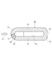
図1は本発明の実施形態に係るガスタービン排気温度検出装置の概略構成図である。本実施形態に係るガスタービン排気温度検出装置2は、ガスタービンエンジン1の排気部に配置され、排気ガスの温度を検出するものである。
FIG. 1 is a schematic configuration diagram of a gas turbine exhaust temperature detection device according to an embodiment of the present invention. The gas turbine exhaust
図1に示すように、ガスタービンエンジン1は、外周ケーシング3、外周ケーシング3の内側に配置された内周ケーシング4、外周ケーシング3と内周ケーシング4との間に配置された金属製のストラット5を備えている。外周ケーシング3及び内周ケーシング4は、それぞれ円筒形状に形成され、これらの円筒形の中心軸線L1がほぼ一致するようにストラット5により連結されている。これによって、外周ケーシング3と内周ケーシング4との間には、環状の排気ガス流路6が形成される。そして、排気ガスは、矢印F1に示す方向(すなわち、排気ガスの流れ方向)に沿って排気ガス流路6を通して、外部に排気される。
As shown in FIG. 1, a
ストラット5は、複数であって、排気ガス流路6の周方向に沿って一定の間隔をもって均等に配置されている。ストラット5の前方(すなわち、排気ガスの上流側)には、ガスタービンエンジン1の最終段の動翼7が配置されている。この動翼7は、回転軸8に固定されている。ガスタービン排気温度検出装置2は、ストラット5に取り付けられた一対の熱電対9,10を備えている。この熱電対9,10は、排気ガスの温度を検出する排気温度検出手段として機能している。なお、本実施形態において、排気温度検出手段として、熱電対9,10のほか、その他の温度センサを用いてもよい。
There are a plurality of
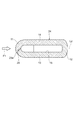
図2はストラットを示す横断面図である。図2に示すように、ストラット5は、断面略楕円状に形成され、排気ガスの上流側に位置する前面壁11と、排気ガスの下流側に位置する後面壁12と、前面壁11と後面壁12との間で互いに平行する側面壁13,14とを有する。そして、前面壁11、後面壁12及び側面壁13,14により囲まれた空間は、外周ケーシング3側から内周ケーシング4にかけて延在する中空部15を形成する。図2において、L2は排気ガスの流れ方向F1に沿う中心線であり、ストラット5は、この中心線L2に対して左右対称である。
FIG. 2 is a cross-sectional view showing the strut. As shown in FIG. 2, the
図1に示すように、前面壁11には、2つの凹部16,17が設けられている。これらの凹部16,17は、排気ガスをその内部に取り入れるように、排気ガスの上流側に向けて開放され、排気ガスの流れ方向F1に沿って延在している。凹部16,17の内部には、熱電対9,10の先端部が挿入されている。
As shown in FIG. 1, the
前面壁11の外周ケーシング3の近傍には、前面壁11を貫通する導入孔18が設けられている。この導入孔18は、動翼7の先端と外周ケーシング3との隙間を流れるチップクリアランス流れ(矢印F2参照)を排気ガスの上流側から中空部15に導入するためのものである。導入孔18は、チップクリアランス流れの方向に沿うように、中心線L2に対し所定角度をもって傾斜している(図2参照)。
An
後面壁12の内周ケーシング4の近傍には、後面壁12を貫通する排出孔19が設けられている。この排出孔19は、中空部15に導入されるチップクリアランス流れを排気ガスの下流側に排出するためのものである。そして、中空部15、導入孔18及び導入孔18は、チップクリアランス流れを排気ガスの上流側から下流側に向けてストラット5を通すための排気ガス流通路を構成する。
A
このように構成されたガスタービン排気温度検出装置2によれば、ストラット5の内部に中空部15が設けられ、前面壁11の外周ケーシング3の近傍には、動翼7のチップクリアランス流れを排気ガスの上流側から中空部15に導入するための導入孔18が設けられているので、チップクリアランス流れを外周ケーシング3付近から中空部15内に取り入れることができる。このチップクリアランス流れは、ストラット5の内部からストラット5を温め、ストラット5の温度を内部から上昇させることができる。このため、より正確な排気ガス温度検出が可能となり、排気ガス温度検出精度の向上を図ることができる。
According to the gas turbine exhaust
しかも、チップクリアランス流れは、外周ケーシング3付近では温度が高く且つ流速が速い。このようにチップクリアランス流れを外周ケーシング3付近から中空部15に取り入れることにより、ストラット5の温度を内部から確実に上昇させると共に、チップクリアランス流れの導入孔18を小さくすることが可能となる。その結果、エンジン性能の低下を軽減することができる。
Moreover, the tip clearance flow has a high temperature and a high flow velocity in the vicinity of the
また、後面壁12の内周ケーシング4の近傍には、中空部15内のチップクリアランス流れを排気ガスの下流側に排出するための排出孔19が設けられている。このようにチップクリアランス流れを外周ケーシング3付近から中空部15に導入させ、内周ケーシング4付近から排出させることにより、中空部15内のチップクリアランス流れの経路を長くすることができる。従って、チップクリアランス流れからストラット5へ伝わる熱量を増やし、ストラット5の温度を確実に上昇させることが可能となる。
A
更に、チップクリアランス流れは旋回しながら流れるので、チップクリアランス流れの旋回に合わせて、中心線L2に対する導入孔18の傾斜角度をつけることにより、チップクリアランス流れをスムーズに中空部15に導入させることができる。これによって、中空部15に導入されるチップクリアランス流れの流量を増やすことが可能となり、ストラット5の内部を温め易くなる。
Further, since the tip clearance flow flows while swirling, the tip clearance flow can be smoothly introduced into the
次に、図3〜図9を参照して本実施形態に係るガスタービン排気温度検出装置2のストラット5の変形例を説明する。
Next, a modification of the
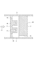
図3に示す変形例では、ストラット20は、3つの導入孔21,22,23を備えている。これらの導入孔21,22,23は、共に前面壁11の外周ケーシング3近傍に設けられ、動翼7のチップクリアランス流れを排気ガスの上流側から中空部15に導入している。そして、これらの導入孔21,22,23は、中心線L2に対する傾斜角度はそれぞれ異なっている。
In the modification shown in FIG. 3, the
このように構成されたストラット20を備えるガスタービン排気温度検出装置は、上記の実施形態と同様な効果が得られるほか、異なる傾斜角度を有する3つの導入孔21,22,23を備えるため、チップクリアランス流れを確実に中空部15に導入させる効果をもたらす。すなわち、ガスタービンエンジン1の運転状態によってチップクリアランス流れの向きは変化し、このように異なる傾斜角度を有する導入孔を複数設けることにより、ガスタービンエンジン1の運転状態が変化した場合も、チップクリアランス流れを確実に中空部15に導入させることが可能となる。
Since the gas turbine exhaust temperature detecting device including the
図4に示す変形例では、ストラット24の導入孔25は、中心線L2に対し所定角度をもって傾斜している。そして、導入孔25の先端部25aは、外方に向けて広がるベルマウス状に形成されている。
In the modification shown in FIG. 4, the
このように構成されたストラット24を備えるガスタービン排気温度検出装置は、上記の実施形態と同様な効果が得られるほか、導入孔25の先端部25aが外方に向けて広がるベルマウス状に形成されているので、チップクリアランス流れをスムーズに中空部15に導入させることができ、中空部15に導入されるチップクリアランス流れの流量を増やすことができる。
The gas turbine exhaust temperature detecting device including the
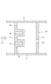
図5に示す変形例では、ストラット26の中空部15には、内部に導入されるチップクリアランス流れを折り返すためのガイド板27,28が設けられている。ガイド板27,28は、導入孔18側から排出孔19側にわたって所定の距離を隔て、上下方向に交互に位置するように配設されている。そして、ガイド27,28の配設によって、中空部15に導入されるチップクリアランス流れは、矢印F3に沿って折り返しながら排出孔19を経由して排気ガスの下流側に排出される。
In the modification shown in FIG. 5, guide
このように構成されたストラット26を備えるガスタービン排気温度検出装置は、上記の実施形態と同様な効果が得られるほか、ガイド板27,28を利用して中空部15に流れるチップクリアランス流れを折り返すことにより、中空部15内のチップクリアランス流れの経路を長くすることができる。従って、チップクリアランス流れからストラット26へ伝わる熱量を増やし、ストラット26の温度を確実に上昇させることが可能となる。
The gas turbine exhaust temperature detecting device including the
図6に示す変形例では、ストラット29の中空部30は、排気ガスの上流側に寄せて配置されている。すなわち、熱電対9,10を設置している前面壁11付近のみを中空にする。
In the modification shown in FIG. 6, the
このように構成されたストラット29を備えるガスタービン排気温度検出装置は、上記の実施形態と同様な効果が得られるほか、中空部30を排気ガスの上流側に寄せて配置することにより、熱電対9,10の周辺部分を局所的に昇温させることができ、排気温度の検出精度の向上を図ることができる。
The gas turbine exhaust temperature detecting device including the
図7に示す変形例では、後面壁12に設けられた排出孔32は、内周ケーシング4から所定の距離離れた場所に配置されている。例えば、排出孔32は、上下方向において凹部16と凹部17との間に配置されている。
In the modification shown in FIG. 7, the discharge hole 32 provided in the
このように構成されたストラット31を備えるガスタービン排気温度検出装置は、上記の実施形態と同様な効果が得られるほか、排出孔32が内周ケーシング4から離れた場所に設けられるので、内周ケーシング4の近傍に設けられた排出孔19と比べて、中空部15内に導入されるチップクリアランス流れは、排出孔32から抜け難くなる。これによって、チップクリアランス流れが中空部15に留まる時間が長くなり、チップクリアランス流れからストラット31へ伝わる熱量を増やすことができる。
The gas turbine exhaust temperature detecting device including the
図8に示す変形例では、後面壁12には、排出孔19のほか、排出孔34,35,36が設けられている。これらの排出孔34,35,36は、外周ケーシング3側から内周ケーシング4側にかけて略等間隔に並設されている。
In the modification shown in FIG. 8, the
このように構成されたストラット33を備えるガスタービン排気温度検出装置は、上記の実施形態と同様な効果が得られるほか、複数の排出孔19,34,35,36を設けることにより、チップクリアランス流れが中空部15に留まる時間を短くし、チップクリアランス流れからストラット33へ伝わる熱量を適宜に低減することが可能となる。その結果、チップクリアランス流れによるストラット33の過度な温度上昇を抑制し、より正確な排気ガス温度検出が可能となる。
The gas turbine exhaust temperature detecting device including the strut 33 configured as described above can obtain the same effect as the above-described embodiment, and also has a plurality of discharge holes 19, 34, 35, and 36, thereby providing a tip clearance flow. It is possible to shorten the time during which the gas stays in the
図9に示す変形例では、ストラット37の側面壁(外壁)13,14には、薄板状のフィン38が複数取り付けられている。このように構成されたストラット37を備えるガスタービン排気温度検出装置は、上記の実施形態と同様な効果が得られるほか、側面壁13,14にフィン38を複数取り付けることにより、ストラット37の伝熱面積を増やし、熱交換を促進させることができ、ストラット37の温度を確実に上昇させることができる。
In the modification shown in FIG. 9, a plurality of thin plate-
本発明に係るガスタービン排気温度検出装置は上述したものに限定されるものではない。本発明に係るガスタービン排気温度検出装置は、各請求項に記載した要旨を変更しないように実施形態に係るガスタービン排気温度検出装置を変形し、又は他のものに適用したものであってもよい。 The gas turbine exhaust temperature detection device according to the present invention is not limited to the one described above. The gas turbine exhaust temperature detection device according to the present invention may be a modification of the gas turbine exhaust temperature detection device according to the embodiment or application to other devices without changing the gist described in each claim. Good.
1…ガスタービンエンジン、2…ガスタービン排気温度検出装置、3…外周ケーシング、4…内周ケーシング、5,20,24,26,29,31,33,37…ストラット、7…動翼、9,10…熱電対(排気温度検出手段)、15,30…中空部、18,21,22,23,25…導入孔、19,32,34,35,36…排出孔、25a…先端部、27,28…ガイド板、38…フィン、F1…排気ガスの流れ方向。
DESCRIPTION OF
Claims (11)
前記ストラットの内部には、ガスタービンの動翼の先端と前記外周ケーシングとの隙間を流れるチップクリアランス流れを排気ガスの上流側から下流側に向けて通すための排気ガス流通路が設けられていることを特徴とするガスタービン排気温度検出装置。 In the gas turbine exhaust temperature detecting device, the exhaust temperature detecting means is attached to the strut connecting the outer casing and the inner casing, and the temperature of the exhaust gas of the gas turbine is detected.
Inside the strut, an exhaust gas flow passage is provided for passing a tip clearance flow that flows through a gap between a tip of a moving blade of a gas turbine and the outer casing from the upstream side to the downstream side of the exhaust gas. A gas turbine exhaust temperature detecting device.
The gas turbine exhaust gas temperature detection device according to claim 1, wherein a thin plate-like fin is attached to the outer wall of the strut.
Priority Applications (1)
| Application Number | Priority Date | Filing Date | Title |
|---|---|---|---|
| JP2008218449A JP2010053745A (en) | 2008-08-27 | 2008-08-27 | Gas turbine exhaust temperature detection device |
Applications Claiming Priority (1)
| Application Number | Priority Date | Filing Date | Title |
|---|---|---|---|
| JP2008218449A JP2010053745A (en) | 2008-08-27 | 2008-08-27 | Gas turbine exhaust temperature detection device |
Publications (1)
| Publication Number | Publication Date |
|---|---|
| JP2010053745A true JP2010053745A (en) | 2010-03-11 |
Family
ID=42069929
Family Applications (1)
| Application Number | Title | Priority Date | Filing Date |
|---|---|---|---|
| JP2008218449A Pending JP2010053745A (en) | 2008-08-27 | 2008-08-27 | Gas turbine exhaust temperature detection device |
Country Status (1)
| Country | Link |
|---|---|
| JP (1) | JP2010053745A (en) |
Cited By (2)
| Publication number | Priority date | Publication date | Assignee | Title |
|---|---|---|---|---|
| CN103075257A (en) * | 2011-10-25 | 2013-05-01 | 通用电气公司 | Turbine radial sensor measurement |
| US9291061B2 (en) | 2012-04-13 | 2016-03-22 | General Electric Company | Turbomachine blade tip shroud with parallel casing configuration |
-
2008
- 2008-08-27 JP JP2008218449A patent/JP2010053745A/en active Pending
Cited By (2)
| Publication number | Priority date | Publication date | Assignee | Title |
|---|---|---|---|---|
| CN103075257A (en) * | 2011-10-25 | 2013-05-01 | 通用电气公司 | Turbine radial sensor measurement |
| US9291061B2 (en) | 2012-04-13 | 2016-03-22 | General Electric Company | Turbomachine blade tip shroud with parallel casing configuration |
Similar Documents
| Publication | Publication Date | Title |
|---|---|---|
| JP4669202B2 (en) | Gas turbine blade | |
| JP4083717B2 (en) | Combustor insulation shield panel and combination of insulation shield panel and shell | |
| AU2013300402B2 (en) | Exhaust heat recovery device | |
| US7311498B2 (en) | Microcircuit cooling for blades | |
| CN106437863B (en) | Turbine engine component | |
| JP2007263112A (en) | Cooling passage and turbine engine component | |
| JP2005337260A (en) | Rotor blade and cooling method for rotor blade | |
| JP2005337259A (en) | Rotor blade | |
| JPH07293202A (en) | Gas turbine moving blade tip cooler | |
| JP2008138665A (en) | Turbine blade and turbine blade cooling system and method | |
| JP2010059966A (en) | Turbine bucket for turbomachine and method of reducing bow wave effect at the turbine bucket | |
| JP2005345093A (en) | Method and device for cooling combustor liner and transition component of gas turbine | |
| JP2008138667A (en) | System to facilitate preferentially distributed recuperated film cooling of turbine shroud assembly | |
| JP2009162119A (en) | Turbine blade cooling structure | |
| JP2005264934A (en) | Turbine air foil and inlet arrangement method for cooling circuit | |
| JP2005337258A (en) | Rotor blade | |
| JP2005337251A (en) | Rotor blade | |
| JP2007170810A (en) | Combustor assembly for turbine engine and liner assembly for combustor assembly | |
| JP5567180B1 (en) | Turbine blade cooling structure | |
| CN105874168A (en) | Gas turbine engine component comprising a trailing edge cooling using angled impingement on surface enhanced with cast chevron arrangements | |
| JP2009257325A (en) | Divergent cooling thimble for combustor liners and related method | |
| JP5111989B2 (en) | System and turbine engine facilitating enhanced local cooling in turbine engine | |
| US20090238695A1 (en) | Full coverage trailing edge microcircuit with alternating converging exits | |
| JP6347893B2 (en) | Turbine blade cooling system with a flow blocker extending in the blade length direction | |
| JP2017025906A (en) | Cooling structure for stationary blade |