JP2010052940A - Rolling element for sheet conveyance of electrophotographic apparatus and injection molding die therefor - Google Patents
Rolling element for sheet conveyance of electrophotographic apparatus and injection molding die therefor Download PDFInfo
- Publication number
- JP2010052940A JP2010052940A JP2009102813A JP2009102813A JP2010052940A JP 2010052940 A JP2010052940 A JP 2010052940A JP 2009102813 A JP2009102813 A JP 2009102813A JP 2009102813 A JP2009102813 A JP 2009102813A JP 2010052940 A JP2010052940 A JP 2010052940A
- Authority
- JP
- Japan
- Prior art keywords
- roller
- rolling element
- outer peripheral
- sheet conveyance
- electrophotographic apparatus
- Prior art date
- Legal status (The legal status is an assumption and is not a legal conclusion. Google has not performed a legal analysis and makes no representation as to the accuracy of the status listed.)
- Granted
Links
Images


Classifications
-
- B—PERFORMING OPERATIONS; TRANSPORTING
- B65—CONVEYING; PACKING; STORING; HANDLING THIN OR FILAMENTARY MATERIAL
- B65H—HANDLING THIN OR FILAMENTARY MATERIAL, e.g. SHEETS, WEBS, CABLES
- B65H27/00—Special constructions, e.g. surface features, of feed or guide rollers for webs
-
- B—PERFORMING OPERATIONS; TRANSPORTING
- B29—WORKING OF PLASTICS; WORKING OF SUBSTANCES IN A PLASTIC STATE IN GENERAL
- B29C—SHAPING OR JOINING OF PLASTICS; SHAPING OF MATERIAL IN A PLASTIC STATE, NOT OTHERWISE PROVIDED FOR; AFTER-TREATMENT OF THE SHAPED PRODUCTS, e.g. REPAIRING
- B29C45/00—Injection moulding, i.e. forcing the required volume of moulding material through a nozzle into a closed mould; Apparatus therefor
- B29C45/0025—Preventing defects on the moulded article, e.g. weld lines, shrinkage marks
- B29C2045/0034—Mould parting lines
-
- B—PERFORMING OPERATIONS; TRANSPORTING
- B29—WORKING OF PLASTICS; WORKING OF SUBSTANCES IN A PLASTIC STATE IN GENERAL
- B29L—INDEXING SCHEME ASSOCIATED WITH SUBCLASS B29C, RELATING TO PARTICULAR ARTICLES
- B29L2031/00—Other particular articles
- B29L2031/32—Wheels, pinions, pulleys, castors or rollers, Rims
- B29L2031/322—Wheels, pinions, pulleys, castors or rollers, Rims made wholly of plastics
-
- B—PERFORMING OPERATIONS; TRANSPORTING
- B65—CONVEYING; PACKING; STORING; HANDLING THIN OR FILAMENTARY MATERIAL
- B65H—HANDLING THIN OR FILAMENTARY MATERIAL, e.g. SHEETS, WEBS, CABLES
- B65H2401/00—Materials used for the handling apparatus or parts thereof; Properties thereof
- B65H2401/10—Materials
- B65H2401/11—Polymer compositions
-
- B—PERFORMING OPERATIONS; TRANSPORTING
- B65—CONVEYING; PACKING; STORING; HANDLING THIN OR FILAMENTARY MATERIAL
- B65H—HANDLING THIN OR FILAMENTARY MATERIAL, e.g. SHEETS, WEBS, CABLES
- B65H2402/00—Constructional details of the handling apparatus
- B65H2402/80—Constructional details of the handling apparatus characterised by the manufacturing process
-
- B—PERFORMING OPERATIONS; TRANSPORTING
- B65—CONVEYING; PACKING; STORING; HANDLING THIN OR FILAMENTARY MATERIAL
- B65H—HANDLING THIN OR FILAMENTARY MATERIAL, e.g. SHEETS, WEBS, CABLES
- B65H2404/00—Parts for transporting or guiding the handled material
- B65H2404/10—Rollers
- B65H2404/13—Details of longitudinal profile
- B65H2404/135—Body
-
- B—PERFORMING OPERATIONS; TRANSPORTING
- B65—CONVEYING; PACKING; STORING; HANDLING THIN OR FILAMENTARY MATERIAL
- B65H—HANDLING THIN OR FILAMENTARY MATERIAL, e.g. SHEETS, WEBS, CABLES
- B65H2801/00—Application field
- B65H2801/03—Image reproduction devices
- B65H2801/06—Office-type machines, e.g. photocopiers
Abstract
Description
この発明は、複写機、ファクシミリ、レーザープリンタ等の電子写真装置内で画像形成されたシートを搬送するシート搬送用転動体及びその製造に使用される射出成形金型に関するものである。
BACKGROUND OF THE
複写機やレーザープリンタ等の電子写真プロセスを利用した電子写真装置は、電子写真プロセスにより感光体上に形成した像を転写紙にトナー像として転写し、この像を転写紙上に定着装置で定着した後、機外に排出する。このような定着装置は、ヒータを内蔵する定着ローラーと、これに圧接する加圧ローラーとからなり、そのニップ部に定着トナー像を担持する転写紙を通紙し、加熱と押圧によってトナーを転写紙に溶融し定着させ、その後に転写紙を排紙コロおよび排紙ローラー等のシート搬送用転動体により機外に排出する。また、定着ローラーの代わりに定着ベルト等の定着部材を使用する定着装置も知られている。 An electrophotographic apparatus using an electrophotographic process such as a copying machine or a laser printer transfers an image formed on a photoreceptor by an electrophotographic process as a toner image onto a transfer paper, and the image is fixed on the transfer paper with a fixing device. After that, it is discharged out of the machine. Such a fixing device is composed of a fixing roller having a built-in heater and a pressure roller in pressure contact with the fixing roller. A transfer paper carrying a fixed toner image is passed through the nip portion, and the toner is transferred by heating and pressing. The paper is melted and fixed on the paper, and then the transfer paper is discharged out of the apparatus by a sheet conveying rolling element such as a paper discharge roller and a paper discharge roller. A fixing device using a fixing member such as a fixing belt instead of the fixing roller is also known.
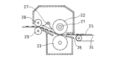
具体的なシート搬送用転動体を図6により説明する。図6は定着ローラーを有する定着装置の概略構成例を示している。図6に示す定着装置は、ヒータ21を内蔵する定着ローラー22に転写紙経路を挟んで従動回転する加圧ローラー23を設けたものであり、図外の転写部より搬送ベルト24により搬送されてきた未定着トナー像を担持する転写紙25は、定着入口ガイド26に案内されて定着ローラー22と加圧ローラー23とのニップ部に挿入され、対のローラー22、23に挟圧された際、トナー像が定着されながら送り出される。定着後、転写紙25の先端は、定着ローラー22のニップ部の下流側に位置する分離爪27の爪先によって定着ローラー22から剥離される。定着ローラー22から剥離された用紙は、搬送経路を通り、その際に回転駆動されている排紙ローラー29と排紙ローラー29に圧接されて従動する排紙コロ28などの間を通って機外に排出される。
A specific sheet conveying rolling element will be described with reference to FIG. FIG. 6 shows a schematic configuration example of a fixing device having a fixing roller. The fixing device shown in FIG. 6 includes a
また、図7に示すカラーレーザープリンタについては、未定着トナー像を担持した転写紙がヒータ内蔵の定着ローラー30と加圧ローラー31の対接部を通過した後、分離爪32で定着ローラー30から引き剥がされ、そのまま排紙コロ33と排紙ローラー34の対接部を通って送り出され、さらに一対の中間ガイドコロ35の間を通った後、回転駆動されている駆動ローラー36と蹴り出し用コロ37の間を通って機外まで搬送される。また、図7中符号32aは加圧ローラー31に接する分離爪である。なお、図7中の符号38はレーザーユニット、39はトナー収納部、40は静電潜像を形成する感光ドラム、41は転写装置、42は紙(シート)収納カセット、43は定着装置をそれぞれ示している。
In the color laser printer shown in FIG. 7, the transfer paper carrying the unfixed toner image passes through the contact portion between the
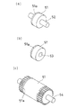
上述したような画像形成装置における、従来の排紙コロ、中間ガイドコロ、蹴り出し用コロなどのシート搬送用転動体を図8(a)、(b)、(c)に示す。図8(a)、(b)、(c)は従来のシート搬送用転動体の斜視図である。図8(a)、(b)に示すシート搬送用転動体は、排紙コロまたは中間ガイドコロとして使用されるものであり、ローラー部51と、その両端に回転軸となる支持軸52又は軸穴53とを有している。図8(c)に示すシート搬送用転動体は、蹴り出し用コロとして用いられるものであり、ローラー部51の両端に歯車付きの支持軸54を有している。このようなシート搬送用転動体は、テトラフルオロエチレン−パーフルオロアルキルビニルエーテル共重合体(PFA)、テトラフルオロエチレン−エチレン共重合体(ETFE)、テトラフルオロエチレン−ヘキサフルオロプロピレン共重合体(FEP)など溶融タイプのフッ素樹脂を用い、射出成形で作られている(下記特許文献1参照)。
8A, 8B, and 8C show sheet conveying rolling elements such as a conventional paper discharge roller, intermediate guide roller, and kicking roller in the image forming apparatus as described above. 8A, 8B, and 8C are perspective views of a conventional sheet conveying rolling element. 8A and 8B is used as a sheet discharge roller or an intermediate guide roller, and includes a
その金型のパーティングラインは、突起状のパーティングライン痕51aが目立たず、仕上げ加工が容易となるように、あるいはシート搬送用転動体の金型からの取り出しが容易となるようにするため、ローラー部51の端部あるいは端部より2mm以内の位置に対応して設けられている(下記特許文献2参照)。なお、端部より2mm以内の位置とは、ローラー部51の肩部(エッジ部)に形成される曲面面取りの大きさに対応したものであり、例えば、肩部の曲面面取りが半径1mmであれば、端部より1mmの位置にパーティングライン(以下、PLと略して記す)が設けられている。
In the parting line of the mold, the protruding
しかし、この場合、シート搬送用転動体の外周のシート摺接面の円周状に、筋状にパーティングライン痕(以下、PL痕と略して記す。)が形成され、転写紙に筋が付くという問題があるため、シート搬送用転動体をバレル研磨あるいはショットブラスト等の後加工することによってPL痕を除去しており、この後加工に手間を要するという問題がある。 However, in this case, parting line marks (hereinafter abbreviated as PL marks) are formed on the circumference of the sheet sliding contact surface on the outer periphery of the sheet conveying rolling element, and the transfer paper has streaks. Since there is a problem of sticking, the PL trace is removed by post-processing the sheet conveying rolling element such as barrel polishing or shot blasting, and there is a problem that this post-processing is troublesome.
このような問題に対して、PLをシート摺接面の長手方向中央部に対応して位置させ、かつ、シート摺接面の長手方向における中央部の外径寸法が、両端部の外径寸法よりも小径となるようにしたシート搬送用転動体が提案されている(下記特許文献2参照)。
For such a problem, the PL is positioned corresponding to the central portion in the longitudinal direction of the sheet sliding contact surface, and the outer diameter dimension of the central portion in the longitudinal direction of the sheet sliding contact surface is the outer diameter dimension of both ends. There has been proposed a sheet conveying rolling element having a smaller diameter (see
また、カラー電子写真装置用のシート搬送用転動体として、転写紙への接圧を低下させて画質を向上させるため、転写紙との接触部をフィルム状としたものも使用されており、このようなシート搬送用転動体を製造する射出成形金型も開示されている(下記特許文献3,4参照)
In addition, as a rolling element for sheet conveyance for a color electrophotographic apparatus, in order to improve the image quality by reducing the contact pressure to the transfer paper, a film-shaped contact portion with the transfer paper is used. An injection mold for manufacturing such a sheet conveying rolling element is also disclosed (see
しかしながら、上記特許文献2に記載されているシート搬送用転動体は、射出成形で生じるヒケ(窪み)を利用して、シート摺接面の長手方向における中央部の外径寸法を、両端部の外径寸法よりも小径となるようにしているため、シート摺接面の外径寸法が小さなシート搬送用転動体では、ヒケでPL痕がシート摺接面より突出しないようにすることが困難な場合もある。また、シート摺接面がフィルム状のシート搬送用転動体でも、外周部の肉厚の関係上、ヒケでPL痕がシート摺接面より突出しないようにすることは困難である。
However, the rolling element for sheet conveyance described in the above-mentioned
このような状況下、シート摺接面の外径寸法が小径で両肩部が曲面面取りされたシート搬送用転動体を得るために、曲面面取りが形成される位置にPLを設定し、曲面面取り部の外径寸法をシート摺接面の外径寸法より若干小径となるようにし、筋状のPL痕が形成されないシート搬送用転動体の製造を試みたが、実際に射出成形されたシート搬送用転動体のシート摺接面のPL近傍には、円周状に半径方向で最大50μm、軸方向で最大100μmの膨らみが生じた。このような膨らみは、転写紙に筋が付く原因となることから、射出成形上がりのシート搬送用転動体を、従来どおりバレル研磨あるいはショットブラスト等の後加工で除去しなければならず、この後加工に手間を要するという問題がある。 Under these circumstances, in order to obtain a rolling element for sheet conveyance in which the outer diameter dimension of the sheet sliding contact surface is small and both shoulders are curved, the PL is set at the position where the curved chamfer is formed, and the curved chamfer is formed. I tried to manufacture a rolling element for sheet conveyance that does not form streak-like PL traces, with the outer diameter dimension of the part being slightly smaller than the outer diameter dimension of the sheet sliding contact surface. In the vicinity of PL on the sheet sliding contact surface of the rolling element for use, circumferential bulges of a maximum of 50 μm in the radial direction and a maximum of 100 μm in the axial direction occurred. Since such swelling causes streaks on the transfer paper, the sheet conveying rolling element after injection molding must be removed by post-processing such as barrel polishing or shot blasting as usual. There is a problem that processing takes time.
なお、上記特許文献4に開示されたような射出成形金型を使用して、シート摺接面にフィルム状部を有し、両肩部が曲面面取りされたローラー部を備えた形状に成形したシート搬送用転動体においても同様である。
In addition, using the injection mold as disclosed in the above-mentioned
そこで、この発明は、シート摺接面の外径寸法が小径であっても、また、薄肉であっても、シート摺接面に膨らみが現れないシート搬送用転動体を提供し、バレル研磨等の後加工を行なうことなく、電子写真装置において高い画質を得られるようにすることを課題とする。 Therefore, the present invention provides a rolling element for conveying a sheet that does not bulge on the sheet sliding contact surface even if the outer diameter dimension of the sheet sliding contact surface is small or thin, barrel polishing, etc. An object is to obtain high image quality in an electrophotographic apparatus without performing post-processing.
上記課題を提供するため、この発明は、ローラー部の両肩部が曲面面取りされた射出成形による電子写真装置のシート搬送用転動体において、ローラー部の少なくとも一端側の肩部をなす曲面部内に、端面方向が外周面方向より小径となる段差を設けたことを特徴としている。 In order to provide the above-described problem, the present invention provides a rolling member for sheet conveyance of an electrophotographic apparatus by injection molding in which both shoulder portions of a roller portion are curved and chamfered, in a curved surface portion forming a shoulder portion on at least one end side of the roller portion The step surface direction is provided with a step whose diameter is smaller than that of the outer peripheral surface direction.
ここで、シート摺接面の外径寸法が小径で両肩部が曲面面取りされたシート搬送用転動体を得るために、曲面面取りが形成される位置にPLを設定し、曲面面取り部の外径寸法をシート摺接面の外径寸法より若干小径となるようにし、筋状のPL痕が形成されないシート搬送用転動体を射出成形で製造した場合でも、シート摺接面のPL近傍に、円周状に半径方向の膨らみが生じた現象について調査した結果、次のことが判明した。 Here, in order to obtain a rolling element for sheet conveyance in which the outer diameter dimension of the sheet sliding contact surface is small and both shoulder portions are curved chamfered, PL is set at a position where the curved chamfer is formed, and the outside of the curved chamfered portion is Even when the diameter dimension is set to be slightly smaller than the outer diameter dimension of the sheet sliding contact surface, and the sheet conveying rolling element in which the streak-like PL trace is not formed is produced by injection molding, in the vicinity of the PL of the sheet sliding contact surface, As a result of investigating the phenomenon of radial bulges in the circumference, the following was found.
すなわち、シート摺接面のPL近傍に生じる膨らみは、射出成形金型の衝合隙間に生じる成形バリではなく、溶融樹脂の流動に起因する収縮差が原因となっている。さらに詳細に説明すると、シート搬送用転動体においては、シート摺接面が平滑である必要があるため、溶融樹脂を射出成形金型のキャビティ内に注入するゲートは、シート搬送用転動体の一方の端面側に設定される。このゲートから溶融樹脂をキャビティ内に注入すると、外周面の樹脂の流れは軸方向に沿った流れになり、端面部では径方向に沿った流れになる。 That is, the swelling generated near the PL of the sheet sliding contact surface is not caused by the molding burr generated in the abutting gap of the injection mold, but is caused by the difference in shrinkage caused by the flow of the molten resin. More specifically, since the sheet sliding contact surface needs to be smooth in the sheet conveying rolling element, the gate for injecting the molten resin into the cavity of the injection mold is one of the sheet conveying rolling elements. Is set to the end face side. When molten resin is injected into the cavity from this gate, the flow of the resin on the outer peripheral surface is a flow along the axial direction, and the flow is along the radial direction at the end surface portion.
そして、溶融樹脂が冷却され固化されると成形収縮が生じるが、結晶性樹脂の場合では、樹脂の流れ方向(MD方向)とその直角方向(CD方向)で顕著な差が現れる。この場合の成形収縮は、MD方向ではMD方向の寸法差を、CD方向ではCD方向の寸法差を言うが、本発明に関して言えば、樹脂の分子配合がMD方向である位置の半径方向寸法の成形収縮と、分子配合がCD方向である位置の半径方向寸法の成形収縮のことを指す。シート搬送用転動体の場合、端面にゲートを配置すると外周面の樹脂の流れはMD方向になり、端面はCD方向になる。
曲面面取りが形成される位置にPLを設定し、曲面面取り部の外径寸法をシート摺接面の外径寸法より若干小径となるようにしたシート搬送用転動体では、PL部に形成されるシート摺接面の外径寸法と曲面面取り部の外径寸法との若干の径差によって、PL部に樹脂のCD方向の配向部が形成されることになる。
このPL部の僅かな段差における樹脂の分子配向の違いによる成形収縮率の差が外周面の形状に影響したのである。
When the molten resin is cooled and solidified, molding shrinkage occurs. However, in the case of a crystalline resin, a significant difference appears between the resin flow direction (MD direction) and its perpendicular direction (CD direction). Mold shrinkage in this case refers to a dimensional difference in the MD direction in the MD direction and a dimensional difference in the CD direction in the CD direction, but in terms of the present invention, the radial dimension at the position where the resin compounding is in the MD direction. It refers to mold shrinkage and mold shrinkage in the radial dimension at a position where the molecular blend is in the CD direction. In the case of a rolling element for sheet conveyance, when a gate is disposed on the end face, the resin flow on the outer peripheral face is in the MD direction, and the end face is in the CD direction.
In a rolling element for sheet conveyance in which PL is set at a position where a curved chamfer is formed and the outer diameter of the curved chamfered portion is slightly smaller than the outer diameter of the sheet sliding contact surface, it is formed in the PL portion. Due to a slight difference in diameter between the outer diameter dimension of the sheet sliding contact surface and the outer diameter dimension of the curved chamfered portion, an alignment portion in the CD direction of the resin is formed in the PL portion.
The difference in molding shrinkage due to the difference in the molecular orientation of the resin at the slight step in the PL part affected the shape of the outer peripheral surface.
このため、この発明に係る射出成形金型では、PLを介して肩部側が小径となるように一方及び他方の型板のキャビティの開口径に径差を設け、ローラー部の外周面側にPLへかけて小径となる面取りを設けることで、配向の違いにより外周面が大径になったとしても面取り部でこれを吸収し、シート摺接面であるローラー部の外周面に円周状の膨らみが生じないようにしたのである。 For this reason, in the injection mold according to the present invention, a diameter difference is provided in the opening diameters of the cavities of one and the other mold plate so that the shoulder side has a small diameter through the PL, and the outer peripheral surface side of the roller part is PL. By providing a chamfer with a small diameter over the edge, even if the outer peripheral surface becomes larger due to a difference in orientation, this is absorbed by the chamfered portion, and the outer peripheral surface of the roller portion which is the sheet sliding contact surface is circumferentially shaped. The bulge was prevented from occurring.
この発明に係るシート搬送用転動体では、上記のように、射出成形金型のPL部近傍に発生する円周状の膨らみがシート摺接面であるローラー部の外周面から突出するように現れることがないので、バレル研磨やショットブラスト等の後加工を省略することができ、成形品の製造工程の合理化を図ることができる。 In the rolling element for sheet conveyance according to the present invention, as described above, the circumferential bulge generated in the vicinity of the PL portion of the injection mold appears so as to protrude from the outer peripheral surface of the roller portion which is the sheet sliding contact surface. Therefore, post-processing such as barrel polishing and shot blasting can be omitted, and the manufacturing process of the molded product can be rationalized.
そして、このシート搬送用転動体を電子写真装置に使用すると、画像が転写されたシートの搬送に際して、ローラー部の円周状の膨らみによりシートに筋が付く現象が防止され、美しい画像を得ることができる。 When this sheet conveying rolling element is used in an electrophotographic apparatus, a phenomenon in which the sheet is streaked due to the circumferential bulge of the roller portion during conveyance of the sheet having the image transferred thereon is prevented, and a beautiful image is obtained. Can do.
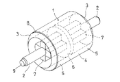
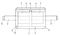
以下、この発明の実施形態を、図1及び図2に示すようなシート搬送用転動体の製造を例として、添付図面に基づいて説明する。 Hereinafter, an embodiment of the present invention will be described with reference to the accompanying drawings, taking as an example the production of a rolling element for sheet conveyance as shown in FIGS.
このシート搬送用転動体は、略円柱状のローラー部1の両端部に、径方向中心部で軸線方向に延びる支持軸2を設けたものとされている。ローラー部1の両肩部3は、曲面面取りされており、シート摺接面となる外周面4は、軸線方向にわたって径が均一な円筒形とされている。ローラー部1の内部には、両端で開放された隙間が形成され、ローラー部1の外周面4は、軸線方向の両端から中央側へかけて薄いフィルム状部5により形成されている。ローラー部1の軸線方向中央部に形成された円盤部6の両端面中央部には、軸線方向へ延びる十字柱状の中芯部7が設けられ、その先端面を基端として、前記支持軸2が形成されている。
This rolling element for sheet conveyance is provided with
ローラー部1の一端側の肩部3と外周面4との境界部には、後述する射出成形金型の固定側型板と可動側型板のキャビティの開口径差による段差8が生じ、支持軸2の先端には、溶融樹脂をキャビティに注入するゲートによるゲート跡9を有する。
At the boundary between the
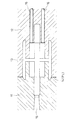
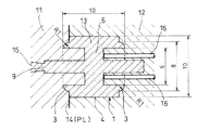
このようなシート搬送用転動体の製造に使用する射出成形金型は、図3に示すように、固定側型板11と可動側型板12とが衝合して内部にキャビティ13が形成されるものとなっている。固定側型板11と可動側型板12のPL14は、上述のローラー部1の一端側の肩部3とローラー部1の外周面4との境界部に位置する。
As shown in FIG. 3, the injection mold used to manufacture such a rolling element for conveying a sheet has a
肩部3を形成する固定側型板11には、溶融樹脂をキャビティ13に注入するゲート15が前記支持軸2の先端に対応する位置で開口するように設けられ、外周面4を形成する可動側型板12には、成形されたシート搬送用転動体をキャビティ13から突き出すための4本の突き出しピン16が設けられている。
On the fixed
上記のような金型を使用して、シート搬送用転動体を成形するには、図4(a)に示すように、固定側型板11と可動側型板12とが衝合してキャビティ13が閉じた状態で、溶融樹脂をゲート15を介してキャビティ13内に射出充填する。そして、保圧・冷却した後、図4(b)に示すように、可動側型板12を固定側型板11から離反させるように移動させて、キャビティ13を開放し、図4(c)に示すように、突き出しピン16を前進させて、成形されたシート搬送用転動体Mをキャビティ13から押し出す。
In order to form a rolling element for sheet conveyance using the mold as described above, as shown in FIG. 4 (a), the fixed
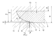
ここで、図5に示すように、PL14に臨む肩部3を形成する固定側型板11のキャビティ13の開口径m1は、外周面4を形成する可動側型板12のキャビティ13の開口径m2よりも小径となっており、可動側型板12のキャビティ13の開口面に臨む部分には、その開口径m2をローラー部外周面対応径d1より小径とする面取り17が設けられている。
Here, as shown in FIG. 5, the opening diameter m 1 of the
例えば、ローラー部外周面対応径d1が10.0mm、ローラー部内周面対応径d2が8.0mmであり、肩部3の半径Rが1mmである場合、固定側型板11のキャビティ13の開口径m1と可動側型板12の開口径m2の半径差は0.1mmとし、可動側型板12のローラー部外周面対応径d1とキャビティ13の開口径m2の半径差である面取り17の深さαは0.05mmとし、面取り17の軸方向の幅βは0.1mmとする。
For example, when the roller portion outer peripheral surface corresponding diameter d 1 is 10.0 mm, the roller portion inner peripheral surface corresponding diameter d 2 is 8.0 mm, and the radius R of the
このような射出成形金型でシート搬送用転動体を成形すると、固定側型板11と可動側型板12のPL14が面取り17の小径側に位置するので、配向の違いによる成形収縮率の差に伴って外周面4がPL14の近傍で大径になろうとしても、面取り17の存在によりこれを吸収し、また、面取り17がない場合に比べて樹脂の流動性が改善され、シート摺接面であるローラー部1の外周面4に円周状の膨らみが生じないようにすることができ、そのような膨らみにより、搬送するシートに筋が付く現象が防止される。ここで、成形後のローラー部1の外周面4には、段差8の近傍に、段差8へかけて小径となるテーパ状の部分が若干残存することがある。
このようなシート搬送用転動体の段差8は、ローラー部外周面4と曲面部の境界部から、端面方向に0.05mm〜曲面面取り半径寸法の1/3の間に設けられている。ここで曲面部とは、図5において面取り17を含む肩部3を指している。段差8を上記範囲に設けることで、PL近傍への膨らみを防止するとともに面取り17の無理抜きが容易にできる。
When the rolling element for sheet conveyance is molded with such an injection mold, the
The
なお、このシート搬送用転動体において、図5に示す固定側型板11のキャビティ13の開口径m1と可動側型板12の開口径m2の半径差は、ローラー部外周面対応径d1の大きさやローラー部1の肉厚および樹脂の種類によって適宜設定するが、0.04〜0.25mmの範囲であれば固定側型板11と可動側型板12がミスマッチした場合でも、ローラー部1の外周面4に対して肩部3が突出することが無いので好ましい。この範囲の下限値より小さければ、固定側型板11と可動側型板12がミスマッチした場合に、ローラー部1の外周面4に対して肩部3が突出する恐れがあり、上限値より大きければデザイン的に他方の肩部3とアンバランスになるため好ましくない。
In this rolling element for sheet conveyance, the difference in radius between the opening diameter m 1 of the
可動側型板12のローラー部外周面対応径d1とキャビティ13の開口径m2の半径差である面取り17の深さα及びその軸方向の幅βも、ローラー部外周面対応径d1の大きさやローラー部1の肉厚および樹脂の種類によって適宜設定するが、面取り深さαが0.02〜0.1mmの範囲、面取り幅βが0.05〜0.3mmの範囲とすることにより、MD方向とCD方向の成形収縮率の差を吸収可能である。この範囲の下限値より小さければ、成形収縮率の差を吸収し難く、ローラー部1の外周面4に膨らみが生じる恐れがあり、上限値より大きければ可動側型板12からの無理抜きが過大になるため、ローラー部1の外周面4の変形等の懸念が生じる。
Even depth α and width in the axial direction of the roller outer peripheral surface of the
また、両肩部3の曲面面取りの半径は、0.6〜3.0mmとし、フィルム状部5の厚さは0.7〜2.0mmとするのがよい。
Moreover, the radius of the curved chamfering of both
また、この発明に係るシート搬送用転動体の材料としては、射出成形が可能なフッ素樹脂であるテトラフルオロエチレン−パーフルオロアルキルビニルエーテル共重合体(PFA)、テトラフルオロエチレン−エチレン共重合体(ETFE)、テトラフルオロエチレン−ヘキサフルオロプロピレン共重合体(FEP)が好適に採用できる。また、上記フッ素樹脂に機械的強度を高める繊維状充填材などを配合してもよい。また、上記フッ素樹脂以外にポリアセタール樹脂、ポリフェニレンサルファイド樹脂、ポリアミド樹脂等の合成樹脂も採用可能である。ただし、これらのフッ素樹脂以外の合成樹脂を使用する場合は、トナーに対する非粘着性を十分に高めることが必要であり、表面にフッ素樹脂被膜を形成したり、フッ素樹脂粉末を配合したりすることが必要である。 The material for the rolling element for sheet conveyance according to the present invention includes tetrafluoroethylene-perfluoroalkyl vinyl ether copolymer (PFA) and tetrafluoroethylene-ethylene copolymer (ETFE), which are fluororesins that can be injection molded. ), Tetrafluoroethylene-hexafluoropropylene copolymer (FEP) can be suitably employed. Moreover, you may mix | blend the fibrous filler etc. which improve mechanical strength with the said fluororesin. In addition to the fluororesin, synthetic resins such as polyacetal resin, polyphenylene sulfide resin, and polyamide resin can also be used. However, when synthetic resins other than these fluororesins are used, it is necessary to sufficiently increase the non-adhesiveness to the toner, and a fluororesin film should be formed on the surface or a fluororesin powder should be blended. is required.
図3〜図5に示すような射出成形金型を用いて、図1及び図2に示すような排紙コロをETFEを材料として射出成形した。この排紙コロは、ローラー部1の直径が10.0mm、内径が8.0mm、軸方向長さが12.0mmで、両肩部3の曲面面取りの半径Rは1mmとなっており、外周面4は、軸方向に平行な円筒形となっている。また、キャビティ13のPL14における開口径m2とm1の半径差は0.1mmであり、面取り深さαが0.05mm、面取り幅βが0.1mmである。そして、成形された排紙コロのPL14が位置する部分を工具顕微鏡で観察したところ、外周面4に膨らみは確認されなかった。
Using an injection mold as shown in FIGS. 3 to 5, a paper discharge roller as shown in FIGS. 1 and 2 was injection molded using ETFE as a material. This discharge roller has a
比較例として、図9に示すローラー部1の直径が12.5mm、内径が10.0mm、軸方向長さが11.5mm、両肩部3の曲面面取りの半径Rが1mm、キャビティ13のPL14における開口径m2とm1の半径差が0.1mmで両肩部3をなす曲面部内に段差を有さない射出成形金型を用いて、この実施例の排紙コロと同材料により排紙コロを射出成形した。そして、成形された排紙コロのPL14が位置する部分を工具顕微鏡で観察したところ、PL14の近傍の外周面4におよそ50μmの突起状の膨らみが確認された。
As a comparative example, the
参考例として、図10に示すローラー部1の直径が10mm、内径が6mm、軸方向長さが10mmで、両肩部3の曲面面取りの半径Rが1mm、両肩部3の大径部の直径が8mmで両肩部3をなす曲面部内に段差を有さない射出成形金型を用いて射出成形した結果、両肩部3の近傍の外周面4に55μmの突起状の膨らみが確認された。この結果から、外周面4の突起状の膨らみはPLが影響するのではなく、樹脂の配向の違いによる成形収縮差によることが明らかになった。
As a reference example, the diameter of the
上記のような実施例の排紙コロを市販のレーザープリンタの定着装置に取り付け、2週間通常運転を行なった。その結果、レーザープリンタから排出された用紙において、筋状の傷は確認されなかった。 The discharge roller of the above example was attached to a fixing device of a commercially available laser printer, and normal operation was performed for 2 weeks. As a result, no streak was found on the paper discharged from the laser printer.
1 ローラー部
2 支持軸
3 肩部
4 外周面
5 フィルム状部
6 円盤部
7 中芯部
8 段差
9 ゲート跡
11 固定側型板
12 可動側型板
13 キャビティ
14 パーティングライン(PL)
15 ゲート
16 突き出しピン
17 面取り
DESCRIPTION OF
15
Claims (12)
ローラー部の少なくとも一端側の肩部をなす曲面部内に、端面方向が外周面方向より小径となる段差を設けたことを特徴とする電子写真装置のシート搬送用転動体。 In the rolling element for sheet conveyance of the electrophotographic apparatus by injection molding in which both shoulder portions of the roller part are curved chamfered,
A rolling element for sheet conveyance of an electrophotographic apparatus, wherein a step having an end face direction smaller in diameter than an outer peripheral face direction is provided in a curved surface portion forming a shoulder portion on at least one end side of a roller portion.
前記固定側型板と可動側型板のパーティングラインは、ローラー部の一端側の肩部と外周面との境界部に位置し、この肩部を形成する一方の型板のキャビティの開口径は、外周面を形成する他方の型板のキャビティの開口径よりも小径として、ローラー部の一端側の肩部が外周面より小径となる段差を設けるようにし、他方の型板のキャビティの開口面に臨む部分には、その開口径をローラー部外周面対応径より小径とする面取りを設けることにより、段差での樹脂の配向の違いによる成形収縮率の差を吸収して、成形後のローラー部の外周面に円周状の膨らみが生じないようにしたことを特徴とする電子写真装置のシート搬送用転動体の射出成形金型。 Used when manufacturing rolling elements for sheet conveyance of an electrophotographic apparatus in which both shoulders of the roller section are chamfered, and injection in which a fixed mold plate and a movable mold plate collide to form an internal cavity In the mold,
The parting line between the fixed mold plate and the movable mold plate is located at the boundary between the shoulder portion on one end side of the roller portion and the outer peripheral surface, and the opening diameter of the cavity of one mold plate forming the shoulder portion Is a smaller diameter than the opening diameter of the cavity of the other mold plate that forms the outer peripheral surface, and a step is provided in which the shoulder portion on one end side of the roller portion has a smaller diameter than the outer peripheral surface, and the opening of the cavity of the other mold plate In the part facing the surface, by providing a chamfer whose opening diameter is smaller than the diameter corresponding to the outer peripheral surface of the roller part, the difference in molding shrinkage due to the difference in resin orientation at the step is absorbed, and the roller after molding An injection mold of a rolling element for sheet conveyance of an electrophotographic apparatus, wherein a circumferential bulge does not occur on the outer peripheral surface of the portion.
Priority Applications (4)
| Application Number | Priority Date | Filing Date | Title |
|---|---|---|---|
| JP2009102813A JP5382509B2 (en) | 2008-04-30 | 2009-04-21 | Rolling element for sheet conveyance of electrophotographic apparatus and injection molding die thereof |
| PCT/JP2009/058338 WO2009133880A1 (en) | 2008-04-30 | 2009-04-28 | Rolling element for carrying sheet of electrophotographic apparatus and injection molding die thereof |
| CN200980115274.2A CN102015499B (en) | 2008-04-30 | 2009-04-28 | Rolling element for carrying sheet of electrophotographic apparatus and injection molding die thereof |
| US12/989,809 US8932193B2 (en) | 2008-04-30 | 2009-04-28 | Sheet feed rolling element for use in an electrophotographic device and mold for injection molding for producing the sheet feed rolling element |
Applications Claiming Priority (5)
| Application Number | Priority Date | Filing Date | Title |
|---|---|---|---|
| JP2008119034 | 2008-04-30 | ||
| JP2008119034 | 2008-04-30 | ||
| JP2008194571 | 2008-07-29 | ||
| JP2008194571 | 2008-07-29 | ||
| JP2009102813A JP5382509B2 (en) | 2008-04-30 | 2009-04-21 | Rolling element for sheet conveyance of electrophotographic apparatus and injection molding die thereof |
Publications (2)
| Publication Number | Publication Date |
|---|---|
| JP2010052940A true JP2010052940A (en) | 2010-03-11 |
| JP5382509B2 JP5382509B2 (en) | 2014-01-08 |
Family
ID=41255096
Family Applications (1)
| Application Number | Title | Priority Date | Filing Date |
|---|---|---|---|
| JP2009102813A Active JP5382509B2 (en) | 2008-04-30 | 2009-04-21 | Rolling element for sheet conveyance of electrophotographic apparatus and injection molding die thereof |
Country Status (4)
| Country | Link |
|---|---|
| US (1) | US8932193B2 (en) |
| JP (1) | JP5382509B2 (en) |
| CN (1) | CN102015499B (en) |
| WO (1) | WO2009133880A1 (en) |
Cited By (1)
| Publication number | Priority date | Publication date | Assignee | Title |
|---|---|---|---|---|
| JP2015027750A (en) * | 2013-07-30 | 2015-02-12 | Ntn株式会社 | Injection molding, injection molding method, and injection molding metal mold |
Families Citing this family (2)
| Publication number | Priority date | Publication date | Assignee | Title |
|---|---|---|---|---|
| JP2018184973A (en) * | 2017-04-24 | 2018-11-22 | キヤノン株式会社 | Drive transmission device |
| CN109318608A (en) * | 2018-11-14 | 2019-02-12 | 安徽宁国天嘉橡塑制品有限公司 | A kind of printer pickup roller |
Citations (7)
| Publication number | Priority date | Publication date | Assignee | Title |
|---|---|---|---|---|
| JPH09315615A (en) * | 1996-01-24 | 1997-12-09 | Ntn Corp | Sheet transporting roller body for image forming device |
| JPH1111731A (en) * | 1997-06-27 | 1999-01-19 | Ricoh Co Ltd | Carrier roller |
| JP2000355434A (en) * | 1999-06-18 | 2000-12-26 | Ntn Corp | Sheet carrying rolling body of image forming device, manufacture and metal mold therefor |
| JP2003231157A (en) * | 2002-02-06 | 2003-08-19 | Ntn Corp | Injection molding die, resin roller and roller for sheet conveyance of imaging device |
| JP2004189485A (en) * | 2002-11-25 | 2004-07-08 | Ntn Corp | Rolling element for conveying sheet of image forming device |
| JP2004314310A (en) * | 2003-04-11 | 2004-11-11 | Ntn Corp | Bearing manufacturing method and injection mold |
| JP2008044753A (en) * | 2006-08-18 | 2008-02-28 | Seiko Epson Corp | Roller, roller molding device, roller molding die, method of manufacturing roller, and recording device |
Family Cites Families (14)
| Publication number | Priority date | Publication date | Assignee | Title |
|---|---|---|---|---|
| US4203509A (en) * | 1978-06-23 | 1980-05-20 | Textron, Inc. | Cargo roller |
| JPS56151149A (en) * | 1980-04-23 | 1981-11-24 | Kubota Ltd | Assembling type roll for continuous casting of slab |
| US5001820A (en) * | 1990-06-27 | 1991-03-26 | Ishikawajima-Harima Jukogyo Kabushiki Kaisha | Roll for rolling mill |
| US6020417A (en) * | 1997-01-24 | 2000-02-01 | Ntn Corporation | Sheet feed members for image forming devices |
| US6032778A (en) * | 1998-12-04 | 2000-03-07 | O'donnell; Steven B. | Cargo roller |
| JP3910481B2 (en) * | 2002-04-24 | 2007-04-25 | 住友ゴム工業株式会社 | Method for manufacturing paper feed roller, paper feed roller manufactured by the manufacturing method, and device for manufacturing paper feed roller |
| JP3915921B2 (en) * | 2003-09-09 | 2007-05-16 | 船井電機株式会社 | Method for manufacturing roller for paper conveyance and image forming apparatus |
| JP2006076772A (en) * | 2004-09-13 | 2006-03-23 | Fuji Photo Film Co Ltd | Carrying roller, carrying device, and method of manufacturing the carrying roller |
| JP2006089172A (en) * | 2004-09-21 | 2006-04-06 | Fuji Xerox Co Ltd | Carrying roller for image forming device |
| JP2006143471A (en) * | 2004-10-18 | 2006-06-08 | Hokushin Ind Inc | Paper feeding roller |
| US8028988B2 (en) * | 2008-01-21 | 2011-10-04 | Honeywell International Inc. | Apparatus and method for stabilizing a moving sheet relative to a sensor |
| US8206277B2 (en) * | 2008-04-30 | 2012-06-26 | Hewlett-Packard Development Company, L.P. | Idler roller assembly having a roller and a shaft the roller being formed such that it remains parallel to contacted media despite deflection of the shaft |
| JP4484168B1 (en) * | 2009-08-12 | 2010-06-16 | 株式会社増田製作所 | Functional roll with lattice-like gas-liquid conduction path structure |
| KR101774895B1 (en) * | 2010-04-08 | 2017-09-05 | 니타 가부시키가이샤 | Paper sheet conveying roller |
-
2009
- 2009-04-21 JP JP2009102813A patent/JP5382509B2/en active Active
- 2009-04-28 WO PCT/JP2009/058338 patent/WO2009133880A1/en active Application Filing
- 2009-04-28 US US12/989,809 patent/US8932193B2/en active Active
- 2009-04-28 CN CN200980115274.2A patent/CN102015499B/en active Active
Patent Citations (7)
| Publication number | Priority date | Publication date | Assignee | Title |
|---|---|---|---|---|
| JPH09315615A (en) * | 1996-01-24 | 1997-12-09 | Ntn Corp | Sheet transporting roller body for image forming device |
| JPH1111731A (en) * | 1997-06-27 | 1999-01-19 | Ricoh Co Ltd | Carrier roller |
| JP2000355434A (en) * | 1999-06-18 | 2000-12-26 | Ntn Corp | Sheet carrying rolling body of image forming device, manufacture and metal mold therefor |
| JP2003231157A (en) * | 2002-02-06 | 2003-08-19 | Ntn Corp | Injection molding die, resin roller and roller for sheet conveyance of imaging device |
| JP2004189485A (en) * | 2002-11-25 | 2004-07-08 | Ntn Corp | Rolling element for conveying sheet of image forming device |
| JP2004314310A (en) * | 2003-04-11 | 2004-11-11 | Ntn Corp | Bearing manufacturing method and injection mold |
| JP2008044753A (en) * | 2006-08-18 | 2008-02-28 | Seiko Epson Corp | Roller, roller molding device, roller molding die, method of manufacturing roller, and recording device |
Cited By (2)
| Publication number | Priority date | Publication date | Assignee | Title |
|---|---|---|---|---|
| JP2015027750A (en) * | 2013-07-30 | 2015-02-12 | Ntn株式会社 | Injection molding, injection molding method, and injection molding metal mold |
| US10695965B2 (en) | 2013-07-30 | 2020-06-30 | Ntn Corporation | Injection molded body, injection molding method, and injection molding die |
Also Published As
| Publication number | Publication date |
|---|---|
| US8932193B2 (en) | 2015-01-13 |
| JP5382509B2 (en) | 2014-01-08 |
| WO2009133880A1 (en) | 2009-11-05 |
| US20110042854A1 (en) | 2011-02-24 |
| CN102015499B (en) | 2015-01-28 |
| CN102015499A (en) | 2011-04-13 |
Similar Documents
| Publication | Publication Date | Title |
|---|---|---|
| US10987885B2 (en) | Method of manufacturing a belt member and the belt member | |
| JP5382509B2 (en) | Rolling element for sheet conveyance of electrophotographic apparatus and injection molding die thereof | |
| US10025243B2 (en) | Gear and image forming apparatus provided with the same | |
| JP2007025196A (en) | Fixing roller and fixing unit using the same | |
| US10322580B2 (en) | Frame, cartridge, image forming apparatus, and method for manufacturing frame | |
| US8594550B2 (en) | Fixing device and image forming apparatus | |
| JP2003241496A (en) | Toner bottle | |
| JP4893871B1 (en) | Bearing / sealing seal member, developing device and image forming apparatus using the same | |
| US6572801B2 (en) | Method of forming an injection molded part having a zero draft side | |
| JP2015223840A (en) | Non-sticking roller production method and non-sticking roller | |
| JP4017607B2 (en) | Stirring screw | |
| JP2003039452A (en) | Rubber roller manufacturing method | |
| JP2003231157A (en) | Injection molding die, resin roller and roller for sheet conveyance of imaging device | |
| JP7022662B2 (en) | Tracking roller and its injection molding method | |
| US20070014954A1 (en) | Resin molded article and mold for manufacturing the same | |
| JP2010046910A (en) | Injection-molded object, injection-molding method, and injection-molding die | |
| JP2000355434A (en) | Sheet carrying rolling body of image forming device, manufacture and metal mold therefor | |
| US8944797B2 (en) | Molding apparatus and method for manufacturing insert molded article | |
| JP2002052446A (en) | Long material manufacturing method and long material obtained therefrom | |
| JP2003160254A (en) | Recording paper conveying roller and its manufacturing method | |
| JP6544111B2 (en) | Mold structure | |
| JP2004314310A (en) | Bearing manufacturing method and injection mold | |
| JP2018072529A (en) | Resin belt, fixing device, image forming apparatus, and method for manufacturing resin belt | |
| JP5976151B2 (en) | Cartridge and image forming apparatus | |
| JP2006171582A (en) | Conveying rod of developing device, method for manufacturing conveying rod, developing device, and image forming apparatus |
Legal Events
| Date | Code | Title | Description |
|---|---|---|---|
| A621 | Written request for application examination |
Free format text: JAPANESE INTERMEDIATE CODE: A621 Effective date: 20120328 |
|
| A131 | Notification of reasons for refusal |
Free format text: JAPANESE INTERMEDIATE CODE: A131 Effective date: 20130611 |
|
| RD13 | Notification of appointment of power of sub attorney |
Free format text: JAPANESE INTERMEDIATE CODE: A7433 Effective date: 20130718 |
|
| A521 | Request for written amendment filed |
Free format text: JAPANESE INTERMEDIATE CODE: A523 Effective date: 20130725 |
|
| A521 | Request for written amendment filed |
Free format text: JAPANESE INTERMEDIATE CODE: A821 Effective date: 20130718 |
|
| A521 | Request for written amendment filed |
Free format text: JAPANESE INTERMEDIATE CODE: A523 Effective date: 20130813 |
|
| RD15 | Notification of revocation of power of sub attorney |
Free format text: JAPANESE INTERMEDIATE CODE: A7435 Effective date: 20130819 |
|
| TRDD | Decision of grant or rejection written | ||
| A01 | Written decision to grant a patent or to grant a registration (utility model) |
Free format text: JAPANESE INTERMEDIATE CODE: A01 Effective date: 20130903 |
|
| A521 | Request for written amendment filed |
Free format text: JAPANESE INTERMEDIATE CODE: A821 Effective date: 20130819 |
|
| A61 | First payment of annual fees (during grant procedure) |
Free format text: JAPANESE INTERMEDIATE CODE: A61 Effective date: 20130919 |
|
| R150 | Certificate of patent or registration of utility model |
Ref document number: 5382509 Country of ref document: JP Free format text: JAPANESE INTERMEDIATE CODE: R150 Free format text: JAPANESE INTERMEDIATE CODE: R150 |
|
| R250 | Receipt of annual fees |
Free format text: JAPANESE INTERMEDIATE CODE: R250 |
|
| R250 | Receipt of annual fees |
Free format text: JAPANESE INTERMEDIATE CODE: R250 |
|
| R250 | Receipt of annual fees |
Free format text: JAPANESE INTERMEDIATE CODE: R250 |
|
| R250 | Receipt of annual fees |
Free format text: JAPANESE INTERMEDIATE CODE: R250 |
|
| R250 | Receipt of annual fees |
Free format text: JAPANESE INTERMEDIATE CODE: R250 |
|
| R250 | Receipt of annual fees |
Free format text: JAPANESE INTERMEDIATE CODE: R250 |
|
| R250 | Receipt of annual fees |
Free format text: JAPANESE INTERMEDIATE CODE: R250 |
|
| R250 | Receipt of annual fees |
Free format text: JAPANESE INTERMEDIATE CODE: R250 |