JP2010052439A - Recording device - Google Patents
Recording device Download PDFInfo
- Publication number
- JP2010052439A JP2010052439A JP2009280310A JP2009280310A JP2010052439A JP 2010052439 A JP2010052439 A JP 2010052439A JP 2009280310 A JP2009280310 A JP 2009280310A JP 2009280310 A JP2009280310 A JP 2009280310A JP 2010052439 A JP2010052439 A JP 2010052439A
- Authority
- JP
- Japan
- Prior art keywords
- recording
- image frame
- marker
- recording material
- image
- Prior art date
- Legal status (The legal status is an assumption and is not a legal conclusion. Google has not performed a legal analysis and makes no representation as to the accuracy of the status listed.)
- Granted
Links
Images


Landscapes
- Handling Of Sheets (AREA)
- Handling Of Continuous Sheets Of Paper (AREA)
- Accessory Devices And Overall Control Thereof (AREA)
- Record Information Processing For Printing (AREA)
- Controlling Sheets Or Webs (AREA)
Abstract
Description
本発明は、記録エリアを画定する画像フレームが長手方向に複数連なる長尺な被記録材をその長手方向に搬送しつつ前記各記録エリアに記録画像を記録するための記録装置に関する。特に、例えばデジタル写真等を連続的にプリントし、それを各画像フレームの境界毎にそのまま折り畳んでアルバム等として使用できる長尺な被記録材を用い、該被記録材の記録エリアに正確に記録を実行する記録装置に関する。
更に、本発明は、インク等の液体をそのヘッドから吐出(噴射)して被記録材(被液体噴射材)に記録を実行する(液体を付着する)インクジェット式記録装置などの液体噴射装置に関するものでもある。
The present invention relates to a recording apparatus for recording a recording image on each recording area while conveying a long recording material having a plurality of image frames defining a recording area in the longitudinal direction. In particular, for example, digital photographs are continuously printed, and the recording material is recorded on the recording area of the recording material using a long recording material that can be folded as it is for each image frame boundary and used as an album. The present invention relates to a recording apparatus that executes
Furthermore, the present invention relates to a liquid ejecting apparatus such as an ink jet recording apparatus that ejects (ejects) a liquid such as ink from a head thereof and executes recording (attaches liquid) on a recording material (liquid ejecting material). It is also a thing.
ここで液体噴射装置とは、インクジェット式記録ヘッドが用いられ、該記録ヘッドからインクを吐出して被記録材に記録を行なうプリンタ、複写機およびファクシミリ等の記録装置に限らず、インクに代えてその用途に対応する液体を前記記録ヘッドに相当する液体噴射ヘッドから被記録材に相当する被液体噴射材に噴射して、前記液体を前記被液体噴射材に付着させる装置を含む意味で用いる。 Here, the liquid ejecting apparatus uses an ink jet recording head, and is not limited to a recording apparatus such as a printer, a copying machine, and a facsimile machine that records ink on a recording material by discharging ink from the recording head. It is used to include a device for ejecting a liquid corresponding to the application from a liquid ejecting head corresponding to the recording head to a liquid ejecting material corresponding to a recording material and attaching the liquid to the liquid ejecting material.
液体噴射ヘッドとして、前記記録ヘッドの他に、液晶ディスプレー等のカラーフィルター製造に用いられる色材噴射ヘッド、有機ELディスプレーや面発光ディスプレー(FED)等の電極形成に用いられる電極材(導電ペースト)噴射ヘッド、バイオチップ製造に用いられる生体有機物噴射ヘッド、精密ピペットとしての試料噴射ヘッド等が挙げられる。 In addition to the recording head, as a liquid ejecting head, a color material ejecting head used for manufacturing a color filter such as a liquid crystal display, and an electrode material (conductive paste) used for forming an electrode such as an organic EL display or a surface emitting display (FED) Examples thereof include an ejection head, a bioorganic matter ejection head used for biochip production, and a sample ejection head as a precision pipette.
従来から下記特許文献1に示す如く、コンピュータの出力装置において使用される記録紙(以下コンピュータ用紙とも言う。)として、1頁ごとにミシン目が入った連続紙がよく知られている。この連続紙には左右の側部に紙フィード用のガイド孔が等ピッチで連続的に設けられている。またミシン目の部位を山折り、谷折りの順で交互につづら折り状に予め折り畳んだ状態で使用されている。このような連続紙は、周面に前記ガイド孔と同一ピッチの複数の突起を備えたトラクタローラによって半ば強制的に紙送りされている。尚、特許文献1には、ガイド孔を検知して用紙の横ずれを補正するためのセンサと移動手段と
してのローラが開示されているが、紙送り方向への位置ずれについては考慮する必要がないとの視点に立つためと思われるが、この点についての開示はない。
Conventionally, as shown in
また、下記特許文献2には、比較的大型の業務用のプリントシステムとして、複数台のインクジェットプリンタを直列的に配置したものが開示されている。このプリントシステムでは、太巻きの極めて長尺のロール紙を使用しており、複数台のインクジェットプリンタを直列的に配置している。しかも、用紙の搬送経路は、多数のガイドローラ等を使用することから、複雑に屈曲し且つ長大となっている。そのため一工程の印刷を完了するまでに繰り出される用紙長もかなりの長さに上る。
従って、この大型の業務用のプリントシステムは、用紙搬送方向の位置ずれが大きな問題となるため、その位置ずれを防止するために用紙にキューマークを付し、このキューマークを用紙搬送方向に配列された複数個のセンサで読み取ることによって、各インクジェットプリンタの印刷位置を補正している。具体的には、各インクジェットプリンタに対応してその上流側に個別にセンサが設けられており、各センサによって読み取られた位置ずれ量は当該センサに対応する下流に位置するインクジェットプリンタの印刷開始タイミングを設定するものである。
この大型の業務用のプリントシステムは、比較的滑らかな用紙の搬送が期待できるロール紙を被記録材とするものであると共に、該ロール紙に対する記録位置は予め厳格に定められてはいない。そのため、上記のような印刷位置の補正で印刷位置のずれが防止できるものと思われる。
Therefore, in this large-sized commercial printing system, the positional deviation in the paper conveyance direction becomes a big problem. Therefore, in order to prevent the positional deviation, a cue mark is attached to the paper, and this cue mark is arranged in the paper conveyance direction. The printing position of each inkjet printer is corrected by reading with a plurality of sensors. Specifically, a sensor is individually provided on the upstream side corresponding to each ink jet printer, and the positional deviation amount read by each sensor is the print start timing of the ink jet printer located downstream corresponding to the sensor. Is set.
This large-sized business printing system uses roll paper that can be expected to convey relatively smooth paper as a recording material, and the recording position on the roll paper is not strictly determined in advance. For this reason, it is considered that the shift of the printing position can be prevented by correcting the printing position as described above.
しかし、記録エリアを画定する画像フレームが長手方向に複数連なる長尺な被記録材をその長手方向に搬送しつつ記録を実行する場合のように、記録される前の段階で記録エリアが予め厳格に定められている連続紙に対して、特許文献2の補正方法をそのまま適用しても、有効性に乏しい。すなわち、特許文献2の補正方法では、記録される前の段階で記録エリアが予め厳格に定められている連続紙に記録を実行する場合には、記録画像がその記録エリアから位置ずれするのを確実に防止することができない問題がある。
However, the recording area is strict in advance before recording, as in the case of performing recording while conveying a long recording material having a plurality of image frames defining the recording area in the longitudinal direction. Even if the correction method of
更には、記録エリアを画定する画像フレームの送り方向長さが設定通りの長さであれば問題は少ないが、製造バラツキなどにより設定長さと実際の長さとがずれていた場合は、被記録材の位置を正確に検出して把握するだけでは足りず、実際に画像を記録すると、その対応する画像フレームに対して、記録エリアからはみ出したり、逆に寸足らずとなったりする問題がある。特に、いわゆる縁なし印刷をする場合は、この問題は無視できない大きな問題となる。 Furthermore, there is little problem if the length of the image frame that defines the recording area is the same as the set length, but if the set length and the actual length deviate due to manufacturing variations, etc. It is not sufficient to accurately detect and grasp the position of the image, and when an image is actually recorded, there is a problem that the corresponding image frame protrudes from the recording area or is not sufficient. In particular, when so-called borderless printing is performed, this problem is a serious problem that cannot be ignored.
本発明の目的は、記録される前の段階で記録エリアが予め厳格に定められている連続紙に記録を行う場合に特有の問題の1つと言える、記録エリアを画定する画像フレームの長さが、設定長さと実際の長さとが製造バラツキ等の原因で少し違っていても、その影響を受けずに記録エリアに正しく記録を実行することができる記録装置、更には液体噴射装置を提供することにある。 An object of the present invention is to determine the length of an image frame that defines a recording area, which is one of problems peculiar to recording on continuous paper in which the recording area is strictly determined in advance before recording. To provide a recording apparatus and a liquid ejecting apparatus that can correctly perform recording in a recording area without being affected even if the set length and the actual length are slightly different due to manufacturing variations, etc. It is in.
上記目的を達成するため本発明に係る記録装置の第1の態様は、記録エリアを画定する画像フレームが長手方向に複数連なる長尺な被記録材をその長手方向に搬送しつつ記録を実行する記録装置であって、被記録材の前記画像フレームの境界位置に対応して配設されて成る位置検出マーカを検出するマーカ検出手段と、該マーカ検出手段で検出された位置検出マーカについてのマーカ位置データから前記画像フレームの長手方向の実測長さYcを演算して求め、該実測長さYcと該画像フレームの設定長さYとの差△Yを求め、対応する画像フレームにこれから記録を行う記録画像の長さに対して、前記差△Y分の補正をして記録を実行する制御部と、を備えたことを特徴とする。 In order to achieve the above object, a first aspect of the recording apparatus according to the present invention performs recording while conveying a long recording material having a plurality of image frames defining a recording area in the longitudinal direction in the longitudinal direction. A recording apparatus, a marker detection unit for detecting a position detection marker arranged corresponding to a boundary position of the image frame of a recording material, and a marker for the position detection marker detected by the marker detection unit From the position data, an actual measurement length Yc in the longitudinal direction of the image frame is calculated and obtained, a difference ΔY between the actual measurement length Yc and the set length Y of the image frame is obtained, and recording is performed on the corresponding image frame. And a control unit that executes recording after correcting the difference ΔY with respect to the length of the recorded image to be performed.
本発明に係る記録装置の第2の態様は、記録エリアを画定する画像フレームが長手方向に複数連なる長尺な被記録材をその長手方向に搬送しつつ記録を実行する記録装置であって、被記録材の前記画像フレームの境界位置に対応して配設されて成る位置検出マーカを検出するマーカ検出手段と、当該被記録材の先頭に位置する1番目の画像フレームについて、その先端位置を検出し、該先端位置を送り量がゼロの位置に移動し、画像フレームの設定長さYだけ搬送方向の下流に送って停止し、前記マーカ検出手段によって2番目の画像フレームとの境界に設けられている位置検出マーカを検出して1番目の画像フレームの実測長さYcを求め、該実測長さYcと該画像フレームの設定長さYとの差△Yを求め、1番目の画像フレームから、これから記録を行う記録画像の長さに対して、前記差△Y分の補正をして記録を実行する制御部と、を備えたことを特徴とする。 A second aspect of the recording apparatus according to the present invention is a recording apparatus that executes recording while conveying a long recording material having a plurality of image frames defining a recording area in the longitudinal direction, in the longitudinal direction, Marker detection means for detecting a position detection marker arranged corresponding to the boundary position of the image frame of the recording material, and the tip position of the first image frame located at the head of the recording material Detect, move the tip position to a position where the feed amount is zero, stop by sending it downstream in the conveying direction by the set length Y of the image frame, and provide it at the boundary with the second image frame by the marker detection means The measured position detection marker is detected to determine the measured length Yc of the first image frame, and the difference ΔY between the measured length Yc and the set length Y of the image frame is determined. From this The length of the recording image to be recorded from, characterized by comprising a control unit that performs recording by the difference △ Y component of correction.
本発明に係る記録装置の第3の態様は、記録エリアを画定する画像フレームが長手方向に複数連なる長尺な被記録材をその長手方向に搬送しつつ記録を実行する記録装置であって、被記録材の前記画像フレームの境界位置に対応して配設されて成る位置検出マーカを検出するマーカ検出手段と、当該被記録材の先頭に位置する1番目の画像フレームについて、その先端位置を記録開始位置に合わせると共にこれから記録を行う記録画像の長さを設定長さYとして記録を実行し、1番目の画像フレームへの前記記録が終了後に該記録終了位置Y1をメモリに記憶し、前記マーカ検出手段によって2番目の画像フレームとの境界に設けられている位置検出マーカを検出してそのマーカ検出位置Ycを求め、これから記録を行う記録画像の長さに対して、前記記録終了位置Y1と前記マーカ検出位置Ycとの差△Y分の補正をして記録を実行する制御部と、を備えたことを特徴とする。 A third aspect of the recording apparatus according to the present invention is a recording apparatus that performs recording while conveying a long recording material having a plurality of image frames defining a recording area in the longitudinal direction, in the longitudinal direction, Marker detection means for detecting a position detection marker arranged corresponding to the boundary position of the image frame of the recording material, and the tip position of the first image frame located at the head of the recording material The recording is performed with the recording start position and the length of the recording image to be recorded as the set length Y, and after the recording to the first image frame is completed, the recording end position Y1 is stored in the memory. The marker detection means detects the position detection marker provided at the boundary with the second image frame, obtains the marker detection position Yc, and determines the length of the recorded image to be recorded. Te, characterized by comprising a control unit for performing recording by a difference △ Y component of the correction of the marker detection position Yc and the recording end position Y1.
ここで、「画像フレーム」とは、記録エリアを画定する単位であり、単一の画像等が記録される記録スペースを意味し、被記録材を冊子状に組み立てた場合に片面(1頁)ごとに割り当てられる場合と、見開き状態の左右両面(2頁)に跨って割り当てられる場合の両方を包含する意味で使用する。
また、「画像フレームの境界位置に対応して配設されて成る位置検出マーカ」とは、隣同士の画像フレームの境界位置に一致して配設されている位置検出マーカと、該境界位置と一定の位置関係をもって配設されている位置検出マーカの両方を含む意味で用いる。
また、「画像」とは、図形や写真に限定されず、文字その他の記録すべきデータ(対象)とされる全てを含む意味で使用する。
Here, the “image frame” is a unit that demarcates a recording area, and means a recording space in which a single image or the like is recorded. When a recording material is assembled in a booklet shape, one side (one page) It is used to include both the case where it is assigned for each and the case where it is assigned across both the left and right sides (2 pages) in a spread state.
In addition, the “position detection marker arranged corresponding to the boundary position of the image frame” refers to the position detection marker arranged corresponding to the boundary position of the adjacent image frames, and the boundary position. This is used to include both position detection markers arranged with a certain positional relationship.
Further, the term “image” is not limited to graphics and photographs, and is used to include all characters and other data to be recorded (target).
本発明によれば、記録される前の段階で記録エリアが予め厳格に定められている連続紙に記録を行う場合に特有の問題の1つと言える、記録エリアを画定する画像フレームの長さが、設定長さと実際の長さとが製造バラツキ等の原因で少し違っていても、その影響を受けずに記録エリアに正しく記録を実行することができる。 According to the present invention, the length of an image frame that defines a recording area, which is one of problems peculiar to recording on continuous paper in which the recording area is strictly determined in advance before recording, is determined. Even if the set length and the actual length are slightly different due to manufacturing variation or the like, it is possible to correctly perform recording in the recording area without being affected by the difference.
本発明の第4の態様は、前記第1のから第3の態様のいずれかにおいて、位置検出マーカは被記録材の長手方向の両サイドに対をなして配設され、該マーカ検出手段で検出された前記両位置検出マーカの両マーカ位置データから被記録材の幅方向の中点に対応する中点位置を演算して求め、該中点位置に基づいて、これから記録を行う記録画像の先頭位置を、被記録材の対応する画像フレームに対して設定して記録を実行する制御を行う制御部と、を備えたことを特徴とする。 According to a fourth aspect of the present invention, in any one of the first to third aspects, the position detection markers are arranged in pairs on both sides in the longitudinal direction of the recording material. A midpoint position corresponding to a midpoint in the width direction of the recording material is calculated from both marker position data of the detected both position detection markers, and based on the midpoint position, a recorded image to be recorded from now on is calculated. And a control unit that controls to execute recording by setting a head position for a corresponding image frame of a recording material.
本発明の第4の態様によれば、マーカ検出手段で検出された前記両位置検出マーカの両マーカ位置データから被記録材の幅方向の中点に対応する中点位置を演算して求め、該中点位置に基づいて、これから記録を行う記録画像の先頭位置を、被記録材の対応する画像フレームに対して設定して記録を実行するので、記録される前の段階で記録エリアが予め厳格に定められている連続紙に対して、記録画像がその記録エリアから位置ずれするのを確実に防止することができる。
具体的には、例えば上記連続紙が搬送方向に対して斜行(スキュー)しても、前記中点位置に基づいて、続いて記録を行う記録画像の先頭位置を設定するので、次の記録を対応する画像フレームに実行するときにそのスキューの影響を抑えることができる。よって、本発明によれば、記録画像が画像フレームに対して搬送方向に位置ずれするのを防止することができる。
According to the fourth aspect of the present invention, the midpoint position corresponding to the midpoint in the width direction of the recording material is calculated from the both marker position data of the both position detection markers detected by the marker detecting means, Based on the midpoint position, the start position of the recorded image to be recorded is set for the corresponding image frame of the recording material and recording is performed. It is possible to reliably prevent the recorded image from being displaced from the recording area for a strictly defined continuous paper.
Specifically, for example, even if the continuous paper is skewed (skewed) with respect to the conveyance direction, the start position of the recording image to be subsequently recorded is set based on the midpoint position, so that the next recording The effect of the skew can be suppressed when the is executed on the corresponding image frame. Therefore, according to the present invention, it is possible to prevent the recorded image from being displaced in the transport direction with respect to the image frame.
また、長尺な連続紙は、その搬送過程で両サイドがガイド部材でガイドされるのが通常であるため、一旦スキューしても当該ガイド部材によって本来の適切な向きに自己復帰することが多い。この自己復帰現象を考慮すると、一時的に生じるスキューを受けなくすることのできる本発明は、この種「記録エリアが予め決められている」連続紙に位置ズレなく記録を実行する為の技術として有効と言える。 In addition, since a long continuous paper is usually guided by guide members on both sides during the conveyance process, the guide member often self-resets to the original proper direction even if it is skewed once. . In consideration of this self-recovery phenomenon, the present invention, which can eliminate the temporarily generated skew, is a technique for executing recording on a continuous sheet of this type “recording area is predetermined” without misalignment. It can be said that it is effective.
また、本発明に係る記録装置の第5の態様は、前記第4の態様において、前記画像フレームは被記録材の幅方向に延びる折り目によって隣同士が区画され、該折り目はミシン目と筋押しによって構成されると共に、該ミシン目と筋押しは交互に繰り返して配設され、前記位置検出マーカはミシン目の位置には配設せず、筋押しの位置に配設されていることを特徴とする。
ここで、「筋押し」とは、プレス装置等によって被記録材を圧縮し、肉厚を幾分薄くして折れ易くする加工及び加工されたものを意味するが、本明細書及び特許請求の範囲では、更に被記録材の肉厚の一部を所定の深さにカットして折れ易くする、いわゆるハーフカットを包含する広範な意味で使用する。また「ミシン目」は周知の通り、交互に切断部と非切断部とを繰り返す構成のものである。
According to a fifth aspect of the recording apparatus of the present invention, in the fourth aspect, the image frame is adjacent to each other by a crease extending in the width direction of the recording material, and the crease is lined with a perforation. The perforation and the muscle push are alternately and repeatedly arranged, and the position detection marker is not arranged at the perforation position but at the muscle push position. And
As used herein, the term “stretching” means a material that has been processed and processed so that the recording material is compressed by a press device or the like, and the wall thickness is somewhat reduced to facilitate folding. In the range, it is used in a broad sense including a so-called half cut, in which a part of the thickness of the recording material is further cut to a predetermined depth to be easily broken. Further, as is well known, the “perforation” has a configuration in which a cut portion and a non-cut portion are alternately repeated.
本発明の第5の態様によれば、前記折り目はミシン目と筋押しによって構成されると共に、該ミシン目と筋押しは交互に繰り返して配設されているので、すべてをミシン目によって構成した場合に比べて被記録材の搬送が円滑になる。
更に、筋押しした箇所は、その位置で折り返したときに外観を害するバリや凹凸等は生ぜず、平滑で美観を備えた端面が形成される。従って、被記録材の記録面側がミシン目のところで内側となり、前記筋押しのところで外側となるように折り畳んで、冊子状の二次加工品に成形した際に、その折り返し部の外観を左右する外側部分が全て筋押しによって構成されることになるので、前記平滑で美観を備えた端面がそのまま形成される効果が得られる。
そして、位置検出マーカは、ミシン目の位置には配設せず、筋押しの位置に配設されているので、前記冊子状の二次加工品に成形した場合に、位置検出マーカは見開き状態の中央には位置せず、左右両端の上下端に位置するので、目立たない。
According to the fifth aspect of the present invention, the fold line is constituted by a perforation and a muscle push, and the perforation and the muscle push are alternately and repeatedly arranged, so that all are constituted by a perforation. Compared to the case, the recording material can be conveyed smoothly.
Further, the creased portion does not generate burrs or irregularities that impair the appearance when folded at that position, and forms a smooth and beautiful end face. Accordingly, when the recording material is folded so that the recording surface side is the inner side at the perforation and the outer side is the stapling, and it is formed into a booklet-like secondary processed product, the appearance of the folded portion affects the appearance. Since all the outer portions are formed by muscle pushing, the effect of forming the smooth and beautiful end face as it is can be obtained.
And since the position detection marker is not arranged at the position of the perforation, but is arranged at the position of the line pushing, the position detection marker is in a spread state when formed into the booklet-like secondary processed product. Because it is located at the upper and lower ends of the left and right ends, it is not conspicuous.
また、本発明に係る記録装置の第6の態様は、前記第5の態様において、前記被記録材は、前記折り目の位置を利用して予めつづら折り状態に折り畳まれていると共に、該被記録材の記録面側が前記ミシン目のところで内側となり、前記筋押しのところで外側となるように折り畳まれていることを特徴とする。
ここで、「予めつづら折り状態に折り畳まれている」とは、Z状に折られ且つ各画像フレームの隣同士が面接触する状態で畳まれていることを意味する。
According to a sixth aspect of the recording apparatus of the present invention, in the fifth aspect, the recording material is preliminarily folded in a spelled state using the position of the fold, and the recording material The recording surface side is folded at the perforation so as to be inside, and at the muscle push, it is folded outside.
Here, “preliminarily folded in a spell-folded state” means that it is folded in a Z-shape and the image frames adjacent to each other are in surface contact with each other.
本発明の第6の態様によれば、前記被記録材は、前記折り目の位置を利用して予めつづら折り状態に折り畳まれているので、記録後にアルバム等の冊子状の二次加工品を形成する場合に、それを容易に作ることができ、更に該被記録材の記録面側が前記ミシン目のところで内側となり、前記筋押しのところで外側となるように折り畳まれているので、その折り返し部の外観を左右する外側部分が全て筋押しによって構成されることになり、もって平滑で美観を備えた端面をそのまま利用した美しい外観形状にて作ることができる。 According to the sixth aspect of the present invention, since the recording material is folded in a spelled state in advance using the position of the fold, a booklet-like secondary processed product such as an album is formed after recording. In this case, it can be easily made, and the recording surface side of the recording material is folded so that it is inside at the perforation, and outside at the muscle push, so that the appearance of the folded portion is All the outer portions that affect the left and right sides are configured by pushing the muscles, so that it is possible to make a beautiful appearance shape using the smooth and beautiful end face as it is.
また、本発明に係る記録装置の第7の態様は、前記第4の態様から第6の態様のいずれかにおいて、前記両位置検出マーカは、対をなす一方が平面視で「コ」の字形状の切り欠き、他方が「逆コ」の字形状の切り欠きにより形成されていることを特徴とする。
ここで、「コ」の字形状の切り欠きとは、該「コ」の字を構成する3辺のうち対向する2辺が両者を結ぶ残りの1辺に対して直交するものに限定されず、対称な台形形状のように対向する2辺が互いに対称的に傾斜するものや「U」字形状等、当該2辺が互いに一定の位置関係を有するものを含む意味で使用する。前記台形形状の切り欠きは搬送経路に引っ掛かりにくいので好ましい。また、「逆コ」の字形状の切り欠きとは、前記「コ」の字形状と対称な逆の形状を意味する。
Further, according to a seventh aspect of the recording apparatus of the present invention, in any one of the fourth to sixth aspects, the pair of position detection markers has a pair of “U” in a plan view. It is characterized in that it is formed by a cutout having a shape and the other is formed by a “reverse U” shaped cutout.
Here, the “U” -shaped notch is not limited to the one in which the two opposite sides among the three sides constituting the “U” shape are orthogonal to the remaining one side connecting the two. It is used to mean that the two opposite sides incline symmetrically like a symmetrical trapezoidal shape, and the “U” shape, etc., that the two sides have a fixed positional relationship with each other. The trapezoidal cutout is preferable because it is not easily caught on the transport path. Further, the “reverse U” -shaped notch means an opposite shape symmetrical to the “U” -shaped shape.
本発明の第7の態様によれば、位置検出マーカの形成が容易に行えると共に、その検出を簡単な検出手段を用いて行うことができる。 According to the seventh aspect of the present invention, the position detection marker can be easily formed, and the detection can be performed using a simple detection means.
また、本発明に係る記録装置の第8の態様は、前記第7の態様において、前記制御部は、前記「コ」の字形状の切り欠きにおける該「コ」の字を構成する3辺のうち対向する2辺に相当する上流側エッジの位置E1u及び下流側エッジの位置E1dを前記検出手段により検出し、両エッジ位置E1uとE1dに基づいて一サイド側の折り目位置F1を演算し、前記「逆コ」の字形状の切り欠きにおける同様の上流側エッジの位置E2u及び下流側エッジの位置E2dを同様に検出し、両エッジ位置E2uとE2dに基づいて他サイド側の折り目位置F2を演算し、これら一サイド側の折り目位置F1と他サイド側の折り目位置F2に基づいて、被記録材の幅方向の中点に対応する中点位置Cを演算して求めるように構成されていることを特徴とする。 Further, an eighth aspect of the recording apparatus according to the present invention is the recording apparatus according to the seventh aspect, wherein the control unit has three sides constituting the “U” in the “U” -shaped notch. The detection means detects an upstream edge position E1u and a downstream edge position E1d corresponding to two opposite sides, calculates a fold position F1 on one side based on both edge positions E1u and E1d, and The same upstream edge position E2u and downstream edge position E2d in the “reverse U” notch are detected in the same manner, and the fold position F2 on the other side is calculated based on both edge positions E2u and E2d. The midpoint position C corresponding to the midpoint in the width direction of the recording material is calculated on the basis of the fold position F1 on one side and the fold position F2 on the other side. It is characterized by.
本発明の第8の態様によれば、一方のサイド側(「コ」の字側)の前記上流側エッジの位置E1u及び下流側エッジの位置E1dから前記折り目位置F1を求め、同様に他方のサイド側(「逆コ」の字側)の上流側エッジの位置E2u及び下流側エッジの位置E2dから当該他サイド側の前記折り目位置F2を求めるので、精度良く両折り目位置F1,F2を求めることができ、もって精度良く前記中点位置Cを求めることができる。 According to the eighth aspect of the present invention, the fold position F1 is obtained from the position E1u of the upstream edge and the position E1d of the downstream edge on one side ("U" side), and similarly, Since the fold position F2 on the other side is obtained from the position E2u of the upstream edge on the side side ("reverse U" side) and the position E2d of the downstream edge, the fold positions F1 and F2 are obtained with high accuracy. Therefore, the midpoint position C can be obtained with high accuracy.
また、本発明に係る記録装置の第9の態様は、前記第8の態様において、前記制御部は、マーカ検出手段により検出される前記各エッジの位置E1u、E1d、E2u及びE2dは、検出に際し許容範囲が定められ、前記両エッジの位置E1uとE1dのうち一方のエッジ位置E1uだけが許容範囲にあるときは前記折り目位置F1は一方のエッジ位置E1uだけで演算し、前記両エッジの位置E2uとE2dのうち一方のエッジ位置E2uだけが許容範囲にあるときは前記折り目位置F2は一方のエッジ位置E2uだけで演算し、前記折り目位置F1とF2の両方が前記検出及び演算により求められたときは、該折り目位置F1とF2の両方に基づいて、前記中点位置Cを演算して求めるように構成され、前記折り目位置F1とF2のうちのF1だけが前記検出及び演算により求められたときは、該折り目位置F1だけに基づいて、前記中点位置Cを演算して求めるように構成され、前記折り目位置F1とF2のうちのF2だけが前記検出及び演算により求められたときは、該折り目位置F2だけに基づいて、前記中点位置Cを演算して求めるように構成されていることを特徴とする。
ここで、「許容範囲」とは、検出手段による上記エッジ位置の検出において、通常の搬送動作で起こる位置データの通常の変動範囲をいい、その結果を用いて問題ないとして定められた変動範囲を意味する。
According to a ninth aspect of the recording apparatus of the present invention, in the eighth aspect, the control unit detects the positions E1u, E1d, E2u, and E2d of the edges detected by the marker detection means. When an allowable range is defined and only one edge position E1u is within the allowable range among the positions E1u and E1d of both edges, the fold position F1 is calculated only by one edge position E1u, and the position E2u of both edges is calculated. And E2d, when only one edge position E2u is within an allowable range, the fold position F2 is calculated only by one edge position E2u, and both the fold positions F1 and F2 are obtained by the detection and calculation. Is configured to calculate and obtain the midpoint position C based on both the fold positions F1 and F2, and only F1 of the fold positions F1 and F2 is obtained by the detection and calculation. When obtained, the midpoint position C is calculated based on only the fold position F1, and only F2 of the fold positions F1 and F2 is obtained by the detection and calculation. In some cases, the midpoint position C is calculated and obtained based only on the crease position F2.
Here, the “allowable range” refers to a normal fluctuation range of position data that occurs in a normal transport operation in the detection of the edge position by the detection means, and a fluctuation range that is determined as no problem using the result. means.
本発明によれば、許容範囲を超えた極端な位置データは、例え検出されても無視される。例えば、被記録材が大きくスキューした場合や上記エッジの一部が破損或いは汚損等している場合のような極端な場合に、その検出結果を用いて上記エッジ位置を演算すると大きな誤差を含むことになる。しかし、本発明によれば、このような許容範囲を超えた位置データは無視されるので、前記極端な場合の影響を受けなくすることができ、これにより検出結果の信頼性を高く保つことができる。すなわち、本発明によれば、検出手段により検出される前記各エッジの位置E1u、E1d、E2u及びE2dは、検出に際し許容範囲が定められているので、該許容範囲を超えた位置データは例え検出されても無視され、これにより検出結果の信頼性を高く保つことができる。 According to the present invention, extreme position data exceeding the allowable range is ignored even if detected. For example, when the recording material is greatly skewed or when the edge is partially damaged or soiled, the edge position is calculated using the detection result to include a large error. become. However, according to the present invention, position data that exceeds such an allowable range is ignored, so that it is possible to eliminate the influence of the extreme case, thereby keeping the detection result highly reliable. it can. That is, according to the present invention, since the permissible range is determined for the positions E1u, E1d, E2u and E2d of the respective edges detected by the detecting means, position data exceeding the permissible range is detected, for example. Is ignored, so that the reliability of the detection result can be kept high.
更に、上流側エッジ位置E1u及びE2uと下流側エッジ位置E1d及びE2dのうち、上流側エッジ位置E1u及びE2uだけ許容範囲の場合にはその検出結果を使い、下流側エッジ位置E1d及びE2dだけが許容範囲であるときはその検出結果を使わない理由を以下に説明する。
前記折り目の位置に跨って前記位置検出マーカを設け、記録が行われた画像フレーム(下流側)とこれから記録が行われる画像フレーム(上流側)の境界の折り目位置を検出して前記中点位置を求めて次の記録を開始する構成にした場合、検出手段を光学式センサーで構成すると、下流側のエッジは記録済みの記録画像によって影響を受けて当該下流側のエッジ位置の検出に誤差を生じやすい。一方、上流側のエッジはその画像フレームが記録前であるため、当該上流側エッジ位置の検出に誤差を生じない。そこで、下流側エッジ位置E1d及びE2dだけが許容範囲であるときはその検出結果を使わないこととした。上流側エッジ位置E1u及びE2uだけでも、その検出位置から一定の距離のところに上記折り目位置F1,F2があると定めておくことにより、ほぼ正確に前記折り目位置を求めることが可能である。
Furthermore, if the upstream edge positions E1u and E2u are within the allowable range among the upstream edge positions E1u and E2u and the downstream edge positions E1d and E2d, the detection result is used, and only the downstream edge positions E1d and E2d are allowed. The reason why the detection result is not used when it is within the range will be described below.
The position detection marker is provided across the position of the fold, and the position of the middle point is detected by detecting the fold position at the boundary between the recorded image frame (downstream) and the recorded image frame (upstream). If the detection means is configured with an optical sensor, the downstream edge is affected by the recorded image, and an error occurs in the detection of the downstream edge position. Prone to occur. On the other hand, since the upstream edge is before the image frame is recorded, no error occurs in the detection of the upstream edge position. Therefore, when only the downstream edge positions E1d and E2d are within the allowable range, the detection result is not used. Even if only the upstream edge positions E1u and E2u are used, it is possible to determine the fold positions almost accurately by determining that the fold positions F1 and F2 are at a certain distance from the detection positions.
また、本発明に係る記録装置の第10の態様は、前記第9の態様において、前記制御部は、前記折り目位置F1とF2の両方が前記検出及び演算により求められなかったときは、これから記録を行う記録画像の先頭位置を前頁の記録終了位置に基づいて設定して記録を実行するように構成されていることを特徴とする。 Further, according to a tenth aspect of the recording apparatus of the present invention, in the ninth aspect, the control unit starts recording when both the fold positions F1 and F2 are not obtained by the detection and calculation. It is characterized in that recording is executed by setting the top position of the recorded image to be performed based on the recording end position of the previous page.
前頁の記録が前記中点位置の検出及び演算に基づいて通常通り実行されていれば、その記録終了位置に基づいてこれから記録を行う記録画像の先頭位置を設定して記録を実行しても、大きく位置ずれすることはほとんどないと言える。従って、本発明によれば、無駄に記録停止となる頻度を減らすことができると共に、位置ずれの問題を現実的には問題とならない程度に維持して記録を続行することができる。また、その次の検出に係る折り目位置F1、F2の両方が続けて検出及び演算により求められない(許容範囲外)という事態の発生は、実際は少ないと予想することができ、その場合には、検出及び演算に基づく前記中点位置に基づいて次の記録画像の先頭位置を正確に設定して記録を行えるので、本発明のように折り目位置F1とF2の両方が求められないことがあっても画一的に記録を停止しないことは現実的に有効である。 If recording on the previous page is normally performed based on the detection and calculation of the midpoint position, recording may be executed by setting the start position of the recording image to be recorded based on the recording end position. It can be said that there is almost no displacement. Therefore, according to the present invention, it is possible to reduce the frequency at which recording is stopped unnecessarily, and to continue recording while maintaining the problem of misalignment to such an extent that it does not actually cause a problem. In addition, the occurrence of a situation where both the crease positions F1 and F2 related to the next detection cannot be continuously obtained by detection and calculation (outside the allowable range) can be expected to be small in reality. Since the start position of the next recorded image can be set accurately based on the midpoint position based on detection and calculation, both the fold positions F1 and F2 may not be obtained as in the present invention. However, it is practically effective not to stop the recording uniformly.
また、本発明に係る記録装置の第11の態様は、前記第10の態様において、前記制御部は、前記折り目位置F1とF2の両方が前記検出及び演算により求められない回数が設定回数Nを越えたときは、記録を停止するように構成されていることを特徴とする。 The eleventh aspect of the recording apparatus according to the present invention is the recording apparatus according to the tenth aspect, wherein the control unit determines that the number of times that both the fold positions F1 and F2 are not obtained by the detection and calculation is a set number N. When it exceeds, recording is stopped.
本発明によれば、前記折り目位置F1とF2の両方が前記検出及び演算により求められないことが連続して続く場合は、何らかの無視できないエラーが発生していると言えるため、その回数を予め設定し、その設定回数Nを越えたときは、記録を停止するようにしたので、大きく位置ずれした記録の発生を防止することができる。 According to the present invention, it can be said that some non-negligible error has occurred when both of the crease positions F1 and F2 are not continuously obtained by the detection and calculation. However, when the set number of times N is exceeded, the recording is stopped, so that it is possible to prevent the occurrence of recording with a large positional deviation.
また、本発明に係る記録装置の第12の態様は、前記第8の態様から第11の態様のいずれかにおいて、対をなす前記「コ」の字形状及び「逆コ」の字形状の切り欠きは、上流側エッジの位置E1u、E2uと下流側エッジの位置E1d、E2dの中間に前記折り目の線が位置するように構成されていることを特徴とする。 A twelfth aspect of the recording apparatus according to the present invention is the recording apparatus according to any one of the eighth aspect to the eleventh aspect, wherein the “U” -shaped and “reverse-U” -shaped cuttings are paired. The notch is characterized in that the fold line is positioned between the upstream edge positions E1u and E2u and the downstream edge positions E1d and E2d.
本発明によれば、該折り目の位置で折られたときに、その切り欠き部分の長さが2分の1に短縮されるので一層目立ち難くなると共に、重なって1つになるので、美観を妨げない。また、前記折り目位置F1とF2の演算を単純化して行うことができる。 According to the present invention, when the fold is folded at the position of the fold, the length of the cut-out portion is shortened by a factor of two, so that it becomes more inconspicuous and overlaps into one. I do not disturb. Further, the calculation of the fold positions F1 and F2 can be simplified.
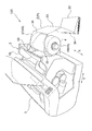
以下、本発明に係る被噴射材の一例である被記録材及び被記録材を使用した二次加工品並びに被記録材の送り込み方法について説明する。最初に本発明の適用対象である液体噴射装置の一例である記録装置の一実施の形態としてインクジェット式記録装置を採り上げて、その全体構成の概略を図面に基づいて説明する。図1はインクジェット式記録装置の概略を示す斜め後方からの斜視図であり、図2は同記録装置の側断面図である。 Hereinafter, a recording material which is an example of a material to be ejected according to the present invention, a secondary processed product using the recording material, and a method for feeding the recording material will be described. First, an ink jet recording apparatus will be described as an embodiment of a recording apparatus which is an example of a liquid ejecting apparatus to which the present invention is applied, and the outline of the entire configuration will be described with reference to the drawings. FIG. 1 is a perspective view showing an outline of an ink jet recording apparatus from an oblique rear side, and FIG. 2 is a side sectional view of the recording apparatus.
インクジェット式記録装置100には、被噴射材の一例である被記録材P(以下単に用紙Pともいう。このうちB5、A4、葉書サイズ等、規格サイズの単票紙を符号S、ロール紙を符号R、つづら折りされた連続紙を符号Zで表す。)に記録を実行する液体噴射実行手段の一例である記録実行手段の主たる構成要素として、主走査方向Xに往復可能にキャリッジガイド軸12によって軸支されたキャリッジ10が設けられている。そして、該キャリッジ10には用紙P等に液体の一例であるインクを吐出(噴射)して記録を行なう液体噴射ヘッドの一例である記録ヘッド13が搭載されている。またキャリッジ10には液体カートリッジの一例であるインクカートリッジ11が装着されている。
In the ink
記録ヘッド13の下方には、記録ヘッド13と対向して記録ヘッド13のヘッド面と用紙P等とのギャップを規定するプラテン28が設けられている。そしてキャリッジ10とプラテン28との間に用紙P等を主走査方向Xと直交する副走査方向Yに所定の搬送量で搬送する動作と、記録ヘッド13を主走査方向Xに一往復させる間に記録ヘッド13から用紙P等にインクを噴射する動作とを交互に繰り返すことによって用紙P等に記録が行われる。
A
また、本実施の形態では単票紙Sの他、ロール紙Rや連続紙Zにも対応できるタイプのインクジェット式記録装置100が採用されている。次に、単票紙Sの搬送経路に従ってインクジェット式記録装置100の構成を更に説明する。先ず最も搬送方向上流側に単票紙Sを積畳する被噴射材積畳部の一例である給送用トレイ5が設けられている。また、給送用トレイ5には単票紙Sの側端面に当接し、副走査方向Yへの円滑な搬送を案内するエッジガイド15が設けられている。給送用トレイ5上の単票紙Sは、給送用ローラ14の回転軸17の回転に伴って、ホッパ16が所定のタイミングで上昇し、給送用ローラ14に向けて押し上げられる。
In the present embodiment, an ink
尚、これらの給送用トレイ5、給送用ローラ14及びホッパ16を含む装置を給送装置2という。そして給送用ローラ14の回転に伴って最上面に位置する単票紙Sから順番に図示しない分離パッドあるいはリタードローラの力を借りて単位数ずつピックアップして搬送方向下流に向かって送られる。
A device including the
給送用ローラ14の下流には、単票紙Sの通過を検出する被噴射材検出手段の一例である図示しない被記録材検出手段(以下単に検出レバーという)が設けられており、該検出レバーの下流には搬送用駆動ローラ19aと搬送用従動ローラ19bとによって構成される搬送用ローラ19が設けられている。このうち搬送用従動ローラ19bは、搬送用従動ローラ用のローラホルダ18の下流側において軸支され、当該ローラホルダ18は、図示しない回転軸を中心に回動可能に設けられ、かつ図示しないねじりコイルばねによって搬送用従動ローラ19bが常に搬送用駆動ローラ19aに圧接したニップ状態になるように回動付勢されている。
Downstream of the feeding
搬送用ローラ19によって挟圧された状態で搬送される単票紙S等(搬送用ローラ19
のニップ点以降はロール紙Rと連続紙Zも同一の搬送経路を辿るので、これらも含まれる。)は、記録ヘッド13の下方の記録部26に導かれ、上述のキャリッジ10及び単票紙
S等の動作によって単票紙S等の記録面のほぼ全面に亘って所望の記録が実行される。記録ヘッド13とその下方において、これと対向して設けられるプラテン28とのギャップは、高精度の記録を実行する上で極めて重要な要素となっており、単票紙S等の厚さの変化に応じて適宜調節されるようになっている。
Cut sheet S or the like that is conveyed while being pinched by the conveying roller 19 (conveying
Since the roll paper R and the continuous paper Z follow the same conveyance path after the nip point, these are also included. ) Is guided to the
記録ヘッド13の下流には、排出用駆動ローラ20aと、排出用従動ローラ20bとによって構成される被噴射材排出手段の一例である排出用ローラ20が設けられ、この排出用ローラ20によって排出された単票紙S等は、更に下流に位置する被噴射材受け部の一例である排出用スタッカ50上の載置面51に排出されるようになっている。なお、図1では排紙スタッカ50は閉状態で示されているが、記録実行時には、その載置面51が上面となるように開かれる。
Disposed downstream of the
排出用従動ローラ20bは、その外周に複数の歯を有する歯付きローラであり、排出用従動ローラ用の図示しないローラホルダによって自由回転可能に軸支されている。排出用従動ローラ20bの上流には、補助歯付きローラ22が設けられ、単票紙S等は該補助歯付きローラ22によってやや下方に押し付けられるようになっている。また、搬送用従動ローラ19bは、搬送用駆動ローラ19aよりその軸芯位置がやや下流側に配設されていて、更に排出用従動ローラ20bは排出用駆動ローラ20aよりその軸芯位置がやや上流側に配設されている。
The discharge driven
このような構成によって単票紙S等は、搬送用ローラ19と排出用ローラ20との間において僅かに下に凸となる俗に「逆ぞり」と呼ばれている湾曲状態となり、記録ヘッド13に対向する位置にある単票紙S等はプラテン28に押し付けられ、これにより単票紙S等の浮き上がりが防止され、正常に記録が実行されるようになっている。尚、補助歯付きローラ22は、排出用従動ローラ20bと同様の歯付きローラから構成されており、図示しない補助歯付きローラ用のローラホルダに軸支されている。
With such a configuration, the cut sheet S or the like is in a curved state called “reverse sled”, which is slightly convex downward between the conveying
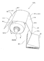
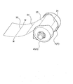
次に、ロール紙Rの搬送経路に従って、ロール紙R特有のインクジェット式記録装置100の基本的な構成を中心に説明する。またロール紙Rの搬送経路は基本的に連続紙Zの搬送経路と同じである。ロール紙Rは所定幅の連続した長尺の用紙がロール芯の周りに巻かれたもので、ロールホルダ45によって遊転自在の状態で保持されている。尚、ロールホルダ45は記録装置本体3に対して固定状態で取り付けられる固定ホルダ47とロール紙R等の幅寸法に応じてロール紙Rの幅寸法に摺動し得るよう、記録装置本体3に対して可動状態で取り付けられる可動ホルダ49とを備えており、後述するように被記録材Pを搬送経路内に供給するためのガイド部材4としての機能を併せ持っている。
Next, the basic configuration of the ink
ロールホルダ45によって保持されたロール紙R等の繰り出し端は、ロール紙Rの搬送経路の入口40から単票紙S用の上述した給送装置2の後面を通って、給送装置2の下方に至り、上述した搬送用ローラ19による挟圧搬送作用を受けながら記録ヘッド13下方の記録部26に導かれる。そして、ロール紙R等は、上述した単票紙Sと同一の搬送経路を辿って排出用ローラ20に至り、排出用スタッカ50より更に下流側に設けられているカッタ装置43まで搬送されて、必要に応じて所定の長さにカットされて排出される。
The feeding end of the roll paper R and the like held by the
また、インクジェット式記録装置100には、被記録材Pに設けられている後述する位置検出マーカMを検出するマーカ検出手段として光学式センサ60と、該光学式センサ60によって検出されたマーカ位置データを基に記録終了位置あるいは記録開始位置またはこれらの双方を制御する制御部(図示せず)とが設けられている。尚、光学式センサ60は、キャリッジ10のプラテン28との対向面であって、記録ヘッド13のノズル列(図示せず)より上流側に設けられている。該光学式センサ60は、キャリッジ10を主走査方向(被記録材Pの搬送方向と直交する方向)に移動させることにより、被記録材Pの両サイドのエッジ位置を検出でき、また、キャリッジ10を停止させた状態で、搬送用ローラ19で被記録材Pの方を副走査方向(被記録材Pの搬送方向)に移動させることにより、被記録材Pの前後方向のエッジ位置を検出できる。
Further, the ink
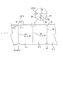
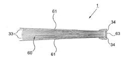
次に、本発明の被記録材について説明する。図3は本発明の被記録材の使用状態を示す斜視図、図4は同被記録材の使用状態を示す側面図、図5は同被記録材の一部を拡大して示す平面図である。本発明の被記録材Pには、複数の画像フレーム30が連続形成されている。画像フレーム30は後述する冊子状の二次加工品とした場合の片面(1頁)に割り当てられる小フレーム31(図6)と、見開き状態の左右両面(2頁)に跨って割り当てられる大フレーム32(図10)とを有している。尚、画像フレーム30は、すべて小フレーム31によって構成することも可能であるし、そのうち一部あるいは全部を大フレーム32によって構成することも可能である。
Next, the recording material of the present invention will be described. 3 is a perspective view showing the usage state of the recording material of the present invention, FIG. 4 is a side view showing the usage state of the recording material, and FIG. 5 is an enlarged plan view showing a part of the recording material. is there. A plurality of image frames 30 are continuously formed on the recording material P of the present invention. The
そして、小フレーム31であれば、画像フレーム30の境界部において、あるいは大フレーム32であれば、画像フレーム30の境界部及び中央部において折り目130となる筋押し33とミシン目34が交互に繰り返すように配設されている。また図示の実施の形態にあっては、被記録材Pとして長尺の被記録原材を予めつづら折り状態に折り畳んだ形状の連続紙Zを使用しており、被記録材Pの記録面が筋押し33のところで外側となり、ミシン目34のところで内側となるように折り畳まれている。
In the case of the
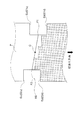
折り目130のうち筋押し33のところに前記位置検出マーカMが設けられている。すなわち、図5に示した如く、該位置検出マーカMは、被記録材Pの長手方向の両サイドに対をなして設けられている。そして、前記両位置検出マーカMは、対をなす一方が平面視で「コ」の字形状の切り欠きM1、他方が「逆コ」の字形状の切り欠きM2により形成されている。ここで、「コ」の字形状の切り欠きとは、該「コ」の字を構成する3辺のうち対向する2辺が両者を結ぶ残りの1辺に対して直交するものに限定されず、対称な台形形状のように対向する2辺が互いに対称的に傾斜するものや「U」字形状等、当該2辺が互いに一定の位置関係を有するものを含む意味で用いられる。なお、前記台形形状の切り欠きは、搬送経路に引っ掛かりにくいので好ましい。また、「逆コ」の字形状の切り欠きM2は、前記「コ」の字形状の切り欠きM1と対称な逆の形状を意味する。
The position detection marker M is provided in the
対をなす前記「コ」の字形状の切り欠きM1及び「逆コ」の字形状の切り欠きM2は、それぞれ上流側エッジEuの位置E1u、E2uと、下流側エッジEdの位置E1d、E2dの中間に、前記折り目130の線が位置するように構成されている。
The “U” -shaped notch M1 and the “reverse U” -shaped notch M2 forming a pair are respectively located at positions E1u and E2u of the upstream edge Eu and positions E1d and E2d of the downstream edge Ed. The line of the
尚、筋押し33とは、プレス装置等によって圧縮し、肉厚を幾分薄くして折れ易くする加工を意味するが、本明細書では、更に被記録材Pの肉厚の一部を所定の深さカットして折れ易くする、いわゆるハーフカットを包含する広範な意味で使用する。またミシン目34は、連続紙Zの用紙幅方向両端部に非切断部35を配置すると共に、交互に切断部36と非切断部35とを繰り返す構成になっていて、非切断部35と切断部36の長さの比率は1:4〜1:6程度と、切断部36の方が、かなり長めになっている。
In addition, the
このような連続紙Zを使用して記録を行なうには、連続紙Zの始端をガイド部材として機能するロールホルダ45の外周面あるいは装着されたロール紙R自体の外周面等に沿わせるようにしてロール紙Rの搬送経路の入口40に差し込み、ロール紙Rと同様の搬送経路を辿って記録部26に送り込まれる。この際、ロールホルダ45はその周面によってつづら折りされた連続紙Zの折り目130を広げて記録部26に連続紙Zを進入させる展延作用を奏するガイド部材4として機能する。
In order to perform recording using such a continuous paper Z, the starting end of the continuous paper Z is set along the outer peripheral surface of the
即ち、ロールホルダ45の外周面の曲面形状によって連続紙Zの山型の鋭角な折れ曲がりが防止され、連続紙Zの折り目130が広げられて平坦な状態になって記録部26に送り込まれる。そして、ロール紙Rと同様の搬送経路を辿って記録が実行され、記録された連続紙Zは、カッタ装置43を動作させることなく、そのままインクジェット式記録装置100の例えば前面側に排出される。
In other words, the curved shape of the outer peripheral surface of the
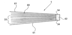
画像フレーム30に画像等が印刷され、記録が実行された展延状態の連続紙Zは、再びつづら折り状態に折り畳まれて以下述べる二次加工品1に成形される。図6は本発明の二次加工品の拡開状態を示す正面斜め上方からの斜視図、図7は同二次加工品を折り畳んだ状態の横断面図である。
The spread continuous paper Z on which an image or the like is printed on the
二次加工品1は、筋押し33が自由端側、ミシン目34が基端側に位置するように記録面を内側にして、つづら折り状態に折り畳まれた冊子状本体60を少なくとも備えている。そして冊子状本体60には、片面(1頁)ごとに画像フレーム30(小フレーム31)が割り当てられ、その全面に亘って、フチあり印刷あるいはフチなし印刷が施されている場合の他、そのうち全部またはその一部が見開き状態の左右両面(2頁)に跨るように画像フレーム30(大フレーム32となる)が割り当てられ、2面に亘ってフチあり印刷あるいはフチなし印刷が施されている場合とが適宜選択される。
The secondary processed
また本実施の形態では、このような冊子状本体60に対して冊子状本体60のミシン目34が形成された基端側部分に綴じ加工が施されており、更にその表面に冊子カバー61を取り付ける装丁加工が施されることによって二次加工品1は構成されている。具体的には冊子カバー61の背表紙裏面に予め熱溶着性の接着剤62を塗布しておき、冊子状本体60を包むようにして冊子カバー61を宛がい、背表紙部分を接着剤62が溶ける所定の温度で加熱することによって綴じ加工と装丁加工とを一挙に行なっている。
In the present embodiment, the booklet
本発明に係る被記録材及び被記録材を使用した二次加工品並びに被記録材の送り込み方法は、以上述べたような構成を基本とするものであるが、本発明の要旨を逸脱しない範囲内の部分的構成の変更や省略等を行なうことも勿論可能である。例えば被記録材Pとして、図8に示す如く、筋押し33とミシン目34とが交互に配設されたロール紙Rを使用して記録を実行することも可能である。因みにこの場合には、折り目を付けて折り曲げる作業は、記録が実行された後に行なうことになり、折り曲げる前は、筋押し33とミシン目34が設けられているが折り目は付けられていない一様な平坦面となっている。
The recording material according to the present invention, the secondary processed product using the recording material, and the recording material feeding method are based on the configuration as described above, but do not depart from the gist of the present invention. Of course, it is possible to change or omit the partial configuration. For example, as the recording material P, as shown in FIG. 8, it is also possible to execute recording by using roll paper R in which the
また、冊子状本体60の綴じ加工としては、図9に示す如く、クリップ式の綴じ具63を使用し、単に冊子状本体60と冊子カバー61の内側部分を挟圧保持することによって綴じる構成であっても構わない。また、図10に示す如く、見開き状態の左右両面の中央部、即ち、大フレーム32であれば、その中央部分に記録が実行されない非記録エリア70を設けることも可能である。このようにした場合には、冊子状本体60の綴じ加工によって、のり代等が必要な場合に、のり代等として非記録エリア70を使用することが可能となる。
Further, as shown in FIG. 9, the booklet-shaped
また、図11に示す如く、ガイド部材4をロールホルダ45とは別体に設けることも可能である。因みに図11の実施の形態では、ガイド部材4は翼片状ないし湾曲した板状に形成されている。
In addition, as shown in FIG. 11, the
次に、本発明のマーカ検出手段である前記光学式センサ60と前記制御部(図示せず)により、記録される前の段階で記録エリアが予め厳格に定められている当該発明に係る連続紙に対して、位置ずれなく記録を実行する動作手順を図12−1、図12−2および図13に基づいて説明する。図12−1及び図12−2は「コ」の字形状の切り欠きM1、及び「逆コ」の字形状の切り欠きM2の位置を検出して前記中点位置Cを求める動作手順を示すフローチャートであり、図13は同動作手順をキャリッジに搭載された光学センサ60の被記録材に対する相対的な動きで示した模式図である。
Next, the continuous paper according to the present invention in which the recording area is strictly determined in advance before recording by the
先ず、キャリッジ10を主走査方向に移動させて光学センサ60を予め定められている基準位置140に位置させる(ステップS1)。そして、光学センサを基準位置140と反対側に向かって移動させ、被記録材PのサイドエッジPs2の位置を検出する(ステップS2)。次に、光学センサ60の位置をサイドエッジPs2の位置から一定距離の設定位置に移動させる(ステップS3)。ここで、この設定位置は切り欠きM2の上流側エッジEu及び下流側エッジEdと交差出来る位置である。被記録材Pを逆転送りさせて下流側エッジEdを光学センサ60より上流側に位置させる(ステップSS4)。続いて、被記録材Pを正転送りし、下流側エッジEdの位置E2dを検出して、そのデータをメモリに記憶する(S5,S6)。更に被記録材Pの正転送りを継続させて上流側エッジEuの位置Eu2を検出して、そのデータをメモリに記憶する(S7,S8)。
First, the
更に正転送りを続けて、該送り方向における前記基準位置140と同じ位置で、停止する。そして、今度はキャリッジ10を主走査方向に移動させて光学式センサ60を基準位置140側に移動させ、被記録材Pのもう一方のサイドエッジPs1の位置を検出する(S9、S10)。後は前記ステップS3からS8と同様の手順で切り欠きM1の下流側エッジEdのエッジ位置E1dと上流側エッジEuのエッジ位置E1uをメモリに記憶する(S11からS15)。その後、キャリッジ10を待機位置に移動させる(図13のS21)。
Further, forward transfer continues and stops at the same position as the
上記E2uとE2dから、切り欠きM2の折り目位置F2を予め設定された位置関係から演算して求め(S16)、同様にE1uとE1dから切り欠きM1の折り目位置F1を予め設定された位置関係から演算して求める(S17)。次に、F1とF2から前記中点位置Cを求める(S18)。これは中点位置であるからF1とF2を足して2で割って求める。そして、中点位置Cに基づいて、次頁の記録画像の先頭位置を設定し(S19)、次頁の記録を開始する(S20)。その際、記録ヘッド13が記録開始位置に合うように被記録材Pを移動する(図13のS21)。いわゆるふち無し印刷の場合は、中点位置Cに次頁の先頭位置を合わせて記録を開始する。
From the above E2u and E2d, the crease position F2 of the notch M2 is calculated from a preset positional relationship (S16). Similarly, the crease position F1 of the notch M1 is calculated from the preset positional relationship from E1u and E1d. Obtained by calculation (S17). Next, the midpoint position C is obtained from F1 and F2 (S18). Since this is the midpoint position, F1 and F2 are added and divided by 2. Then, based on the midpoint position C, the head position of the recording image of the next page is set (S19), and the recording of the next page is started (S20). At that time, the recording material P is moved so that the
次に、マーカ検出手段により検出される前記各エッジEu,Edの位置データE1u、E1d、E2u及びE2dの大きさとして、検出に際し許容範囲が定められている場合の制御について図14、図15−1及び図15−2に基づいて説明する。 Next, FIG. 14 and FIG. 15- about the control in the case where an allowable range is determined as the size of the position data E1u, E1d, E2u and E2d of each edge Eu and Ed detected by the marker detection means. 1 and FIG. 15-2.
切り欠きM2のエッジEu,Edを前記したように検出し(ステップS30)、その検出によって得られたエッジ位置データE2u及びE2dが許容範囲内のものかを判定する(S31)。許容範囲内であるときは、前記と同様にE2u及びE2dに基づいて切り欠きM2の対応する折り目位置F2を演算して求める(S32)。一方、ステップ31で、Noと判定されたときは、一方のエッジ位置データE2uが許容範囲内かを判定する(S36)。許容範囲内であるときは、E2uだけに基づいて切り欠きM2の対応する折り目位置F2を予め定められた関係づけ(一方のE2uだけに基づいて折り目位置F2を演算する為の予め定められた計算式)に基づいて演算して求める(S37)。ステップ36でNoと判定されたときは、F2は求めない(S38)。
The edges Eu and Ed of the notch M2 are detected as described above (step S30), and it is determined whether the edge position data E2u and E2d obtained by the detection are within an allowable range (S31). If it is within the allowable range, the corresponding crease position F2 of the notch M2 is calculated based on E2u and E2d as described above (S32). On the other hand, when it is determined No in
続いて同様に切り欠きM1のエッジEu,Edを検出し(ステップS33)、その検出によって得られたエッジ位置データE1u及びE1dが許容範囲内のものかを判定する(S34)。許容範囲内であるときは、前記と同様にE1u及びE1dに基づいて切り欠きM1の対応する折り目位置F1を演算して求める(S35)。一方、ステップ34で、Noと判定されたときは、一方のエッジ位置データE1uが許容範囲内かを判定する(S39)。許容範囲内であるときは、E1uだけに基づいて切り欠きM1の対応する折り目位置F1を予め定められた関係づけ(一方のE1uだけに基づいて折り目位置F1を演算する為の予め定められた計算式)に基づいて演算して求める(S40)。ステップ39でNoと判定されたときは、F1は求めない(S41)。
Subsequently, the edges Eu and Ed of the notch M1 are similarly detected (step S33), and it is determined whether the edge position data E1u and E1d obtained by the detection are within the allowable range (S34). If it is within the allowable range, the corresponding crease position F1 of the notch M1 is calculated based on E1u and E1d as described above (S35). On the other hand, when it is determined No in
次に、ステップ42において、以上の演算結果を受けて場合分けを行う。すなわち、(1)F1とF2の両方のデータがある場合は、前記と同様にF1とF2に基づいて中点位置Cを求める(S43)。ステップ42において、(2)F1のデータだけが有り、F2のデータが無いときは、F1だけで中点位置Cを予め定められた関係づけ(一方のF1だけに基づいて中点位置Cを演算する為の予め定められた計算式)に基づいて演算して求める(S46)。ステップ42において、(3)F2のデータだけが有り、F1のデータが無いときは、F2だけで中点位置Cを予め定められた関係づけ(一方のF2だけに基づいて中点位置Cを演算する為の予め定められた計算式)に基づいて演算して求める(S47)。 Next, in step 42, cases are classified according to the above calculation results. That is, (1) if both F1 and F2 data exist, the midpoint position C is obtained based on F1 and F2 as described above (S43). In step 42, (2) when there is only F1 data and there is no F2 data, the midpoint position C is determined in advance by F1 alone (the midpoint position C is calculated based only on one F1). The calculation is performed based on a predetermined calculation formula (S46). In step 42, (3) when only F2 data exists and F1 data does not exist, the midpoint position C is preliminarily related only by F2 (the midpoint position C is calculated based on only one F2). The calculation is performed based on a predetermined calculation formula (S47).
そして、上記のようにそれぞれ求められた中点位置Cに基づいて次頁の記録画像の先頭位置を設定し(S44)、次頁の記録を開始する(S45)。 Then, the head position of the recording image of the next page is set based on the midpoint position C obtained as described above (S44), and recording of the next page is started (S45).
一方、ステップ42において、(4)F1とF2の両方のデータが無いときは、前頁の記録終了位置に基づいて、次頁の記録画像の先頭位置を設定して、記録を継続する(S48,S49)。そして、F1とF2の両方のデータが無い状態が連続して何回続くかをカウントし、それが設定回数Nを越えたとき(S48)、記録を停止する(S50)。 On the other hand, in step 42, (4) when there is no data for both F1 and F2, based on the recording end position of the previous page, the head position of the recording image of the next page is set and recording is continued (S48). , S49). Then, it counts how many times the state in which there is no data in both F1 and F2 continues, and when it exceeds the set number N (S48), the recording is stopped (S50).
上記した本発明に係る被記録材および記録装置によれば、以下の作用効果が得られる。マーカ検出手段である光学式センサ60により検出された前記両位置検出マーカM1,M2の両マーカ位置データから被記録材Pの幅方向の中点に対応する中点位置Cを演算して求め、該中点位置Cに基づいて、これから記録を行う記録画像の先頭位置を、被記録材Pの対応する画像フレーム30に対して設定して記録を実行するので、記録される前の段階で記録エリアが予め厳格に定められている連続紙に対して、記録画像がその記録エリアから位置ずれするのを確実に防止することができる。
長尺な連続紙は、その搬送過程で両サイドがガイド部材でガイドされるのが通常であるため、一旦スキューしても当該ガイド部材によって本来の適切な向きに自己復帰することが多い。この自己復帰現象を考慮すると、一時的に生じるスキューを受けなくすることのできる本発明は、この種「記録エリアが予め決められている」連続紙に位置ズレなく記録を実行する為の技術として有効と言える。
According to the recording material and the recording apparatus according to the present invention described above, the following effects can be obtained. A midpoint position C corresponding to a midpoint in the width direction of the recording material P is obtained by calculating from both marker position data of the both position detection markers M1 and M2 detected by the
Since long continuous paper is usually guided on both sides by a guide member during the conveyance process, even if it is once skewed, the guide member often self-resets to the original proper direction. In consideration of this self-recovery phenomenon, the present invention, which can eliminate the temporarily generated skew, is a technique for executing recording on a continuous sheet of this type “recording area is predetermined” without misalignment. It can be said that it is effective.
また、前記折り目130はミシン目34と筋押し33によって構成されると共に、該ミシン目34と筋押し33は交互に繰り返して配設され、前記位置検出マーカMはミシン目の位置には配設せず、筋押し33の位置に配設されているものは、すべてをミシン目34によって構成した場合に比べて被記録材Pの搬送が円滑になる。
更に、筋押し33の箇所は、その位置で折り返したときに外観を害するバリや凹凸等は生ぜず、平滑で美観を備えた端面が形成される。従って、被記録材Pの記録面側がミシン目34のところで内側となり、前記筋押し33のところで外側となるように折り畳んで、冊子状の二次加工品に成形した際に、その折り返し部の外観を左右する外側部分が全て筋押しによって構成されることになるので、前記平滑で美観を備えた端面がそのまま形成される効果が得られる。
そして、位置検出マーカM1、M2は、ミシン目34の位置には配設せず、筋押し33の位置に配設されているので、前記冊子状の二次加工品に成形した場合に、位置検出マーカM1、M2は見開き状態の中央には位置せず、左右両端の上下端に位置するので、目立たない。
Further, the
Further, the
And since the position detection markers M1 and M2 are not arranged at the position of the
また、前記折り目130の位置を利用して予めつづら折り状態に折り畳まれていると共に、該被記録材Pの記録面側が前記ミシン目34のところで内側となり、前記筋押し33のところで外側となるように折り畳まれているものは、記録後にアルバム等の冊子状の二次加工品を形成する場合に、それを容易に作ることができ、更に該被記録材Pの記録面側が前記ミシン目のところで内側となり、前記筋押しのところで外側となるように折り畳まれているので、その折り返し部の外観を左右する外側部分が全て筋押し33によって構成されることになり、もって平滑で美観を備えた端面をそのまま利用した美しい外観形状にて作ることができる。
In addition, the position of the
また、当該制御部は、前記「コ」の字形状の切欠きM1における該「コ」の字を構成する3辺のうち対向する2辺に相当する上流側エッジの位置E1u及び下流側エッジの位置E1dを前記検出手段により検出し、その検出された両エッジ位置E1uとE1dに基づいて一サイド側の切り欠きM1の折り目位置F1を演算し、前記「逆コ」の字形状の切り欠きM2における同様の上流側エッジの位置E2u及び下流側エッジの位置E2dを同様に検出し、両エッジ位置E2uとE2dに基づいて他サイド側の切り欠きM2の折り目位置F2を演算し、これら折り目位置F1とF2に基づいて、被記録材Pの幅方向の中点に対応する中点位置Cを演算して求めるように構成されているので、精度良く両折り目位置F1,F2を求めることができ、もって精度良く前記中点位置Cを求めることができる。 In addition, the control unit controls the position E1u of the upstream edge corresponding to two opposite sides among the three sides constituting the “U” shape in the “U” -shaped cutout M1 and the downstream edge. The position E1d is detected by the detection means, and the crease position F1 of the cutout M1 on one side is calculated based on the detected both edge positions E1u and E1d, and the “reverse U” cutout M2 is calculated. The same upstream edge position E2u and downstream edge position E2d are detected in the same manner, and the fold position F2 of the notch M2 on the other side is calculated based on both edge positions E2u and E2d. And F2, the midpoint position C corresponding to the midpoint in the width direction of the recording material P is calculated and obtained. Therefore, the double fold positions F1 and F2 can be obtained with high accuracy. With the above accuracy The point position C can be obtained.
更に、当該制御部として、マーカ検出手段により検出される前記各エッジの位置E1u、E1d、E2u及びE2dとして、検出に際し許容範囲が定められているものは、以下のようにすることで、すぐれた効果が得られる。
すなわち、前記両エッジの位置E1uとE1dのうち一方のエッジ位置E1uだけが許容範囲にあるときは前記折り目位置F1は一方のエッジ位置E1uだけで演算し、前記両エッジの位置E2uとE2dのうち一方のエッジ位置E2uだけが許容範囲にあるときは前記折り目位置F2は一方のエッジ位置E2uだけで演算し、前記折り目位置F1とF2の両方が前記検出及び演算により求められたときは、該折り目位置F1とF2の両方に基づいて、前記中点位置Cを演算して求めるように構成され、前記折り目位置F1とF2のうちのF1だけが前記検出及び演算により求められたときは、該折り目位置F1だけに基づいて、前記中点位置Cを演算して求めるように構成され、前記折り目位置F1とF2のうちのF2だけが前記検出及び演算により求められたときは、該折り目位置F2だけに基づいて、前記中点位置Cを演算して求める。
Further, as the control unit, the permissible ranges for the positions E1u, E1d, E2u and E2d detected by the marker detection means are determined by the following. An effect is obtained.
That is, when only one edge position E1u is within the allowable range of the positions E1u and E1d of both edges, the fold position F1 is calculated only by one edge position E1u, and the positions E2u and E2d of both edges are calculated. When only one edge position E2u is within the allowable range, the fold position F2 is calculated only by one edge position E2u, and when both the fold positions F1 and F2 are obtained by the detection and calculation, Based on both the positions F1 and F2, the midpoint position C is calculated and obtained, and when only F1 of the fold positions F1 and F2 is obtained by the detection and calculation, the crease The midpoint position C is calculated based on only the position F1, and only F2 of the fold positions F1 and F2 is determined by the detection and calculation. Is calculated by calculating the midpoint position C based only on the crease position F2.
これにより、許容範囲を超えた極端な位置データは、例え検出されても無視される。例えば、被記録材Pが大きくスキューした場合や上記エッジEu,Edの一部が破損或いは汚損等している場合のような極端な場合に、その検出結果を用いて上記エッジ位置を演算すると大きな誤差を含むことになる。しかし、本発明によれば、このような許容範囲を超えた位置データは無視されるので、前記極端な場合の影響を受けなくすることができ、これにより検出結果の信頼性を高く保つことができる。 Thereby, even if extreme position data exceeding the allowable range is detected, it is ignored. For example, when the recording material P is greatly skewed or in extreme cases such as when the edges Eu and Ed are partially damaged or soiled, it is large to calculate the edge position using the detection result. It will contain errors. However, according to the present invention, position data that exceeds such an allowable range is ignored, so that it is possible to eliminate the influence of the extreme case, thereby keeping the detection result highly reliable. it can.
更に、上流側エッジ位置E1u及びE2uと下流側エッジ位置E1d及びE2dのうち、上流側エッジ位置E1u及びE2uだけ許容範囲の場合にはその検出結果を使い、下流側エッジ位置E1d及びE2dだけが許容範囲であるときはその検出結果を使わない理由を以下に説明する。
前記折り目130の位置に跨って前記位置検出マーカM1,M2を設け、記録が行われた画像フレーム30(下流側)とこれから記録が行われる画像フレーム30(上流側)の境界の折り目130の位置を検出して前記中点位置Cを求めて次の記録を開始する構成にした場合、検出手段を光学式センサー60で構成すると、下流側のエッジEdは記録済みの記録画像によって影響を受けて当該下流側のエッジ位置の検出に誤差を生じやすい。一方、上流側のエッジEuはその画像フレーム30が記録前であるため、当該上流側エッジ位置の検出に誤差を生じない。そこで、下流側エッジ位置データE1d及びE2dだけが許容範囲であるときはその検出結果を使わないこととしたものである。上流側エッジ位置データE1u及びE2uだけでも、その検出位置から一定の距離のところに上記折り目位置F1,F2があると定めておくことにより、ほぼ正確に前記折り目130位置を求めることが可能である。
Furthermore, if the upstream edge positions E1u and E2u are within the allowable range among the upstream edge positions E1u and E2u and the downstream edge positions E1d and E2d, the detection result is used, and only the downstream edge positions E1d and E2d are allowed. The reason why the detection result is not used when it is within the range will be described below.
The position detection markers M1 and M2 are provided across the position of the
また、前記制御部が、前記折り目位置F1とF2の両方が前記検出及び演算により求められなかったときは、これから記録を行う記録画像の先頭位置を前頁の記録終了位置に基づいて設定して記録を実行するようにしたものは、以下の作用効果が得られる。 In addition, when both the crease positions F1 and F2 are not obtained by the detection and calculation, the control unit sets the start position of the recording image to be recorded based on the recording end position of the previous page. The following effects are obtained by performing the recording.
前頁の記録が前記中点位置Cの検出及び演算に基づいて通常通り実行されていれば、その記録終了位置に基づいてこれから記録を行う記録画像の先頭位置を設定(一致させる場合と一定の距離離間させる場合の両方を含む)して記録を実行しても、大きく位置ずれすることはほとんどないと言える。従って、本発明によれば、無駄に記録停止となる頻度を減らすことができると共に、位置ずれの問題を現実的には問題とならない程度に維持して記録を続行することができる。また、その次の検出に係る折り目位置F1、F2の両方が続けて検出及び演算により求められない(許容範囲外)という事態の発生は、実際は少ないと予想することができ、その場合には、検出及び演算に基づく前記中点位置Cに基づいて次の記録画像の先頭位置を正確に設定して記録を行えるので、本発明のように折り目位置F1とF2の両方が求められないことがあっても画一的に記録を停止しないことは現実的に有効である。 If the recording on the previous page is normally performed based on the detection and calculation of the midpoint position C, the start position of the recorded image to be recorded is set (consistent with the case where the recording is to be performed based on the recording end position. It can be said that there is almost no significant displacement even when recording is performed with both of them being separated. Therefore, according to the present invention, it is possible to reduce the frequency at which recording is stopped unnecessarily, and to continue recording while maintaining the problem of misalignment to such an extent that it does not actually cause a problem. In addition, the occurrence of a situation where both the crease positions F1 and F2 related to the next detection cannot be continuously obtained by detection and calculation (outside the allowable range) can be expected to be small in reality. Since the start position of the next recorded image can be accurately set based on the midpoint position C based on the detection and calculation, both the fold positions F1 and F2 may not be obtained as in the present invention. However, it is practically effective not to stop the recording uniformly.
また、前記制御部が、前記折り目位置F1とF2の両方が前記検出及び演算により求められない回数が設定回数Nを越えたときは、記録を停止するように構成されているものは、前記折り目位置F1とF2の両方が前記検出及び演算により求められないことが連続して続く場合は、何らかの無視できないエラーが発生していると言えるため、その回数を予め設定し、その設定回数Nを越えたときは、記録を停止するようにすることで、大きく位置ずれした記録の発生を防止することができる。 The controller is configured to stop recording when the number of times that both of the fold positions F1 and F2 cannot be obtained by the detection and calculation exceeds a set number N. If both the positions F1 and F2 are not continuously obtained by the detection and calculation, it can be said that some kind of non-negligible error has occurred. Therefore, the number of times is set in advance and the set number N is exceeded. In such a case, by stopping the recording, it is possible to prevent the occurrence of the recording that is largely displaced.
また、対をなす前記「コ」の字形状及び「逆コ」の字形状の切り欠きM1,M2が、上流側エッジEuの位置と下流側エッジEdの位置の中間に前記折り目130の線が位置するように構成されているものは、該折り目130の位置で折られたときに、その切り欠き部分の長さが2分の1に短縮されるので一層目立ち難くなると共に、重なって1つになるので、美観を妨げない。また、前記折り目位置F1とF2の演算を単純化して行うことができる。
In addition, the notches M1 and M2 of the “U” shape and the “reverse U” shape that form a pair have a line of the
上記のようなマーカ検出手段による位置検出マーカの検出とその検出に基づく制御部による動作制御を前提に、以下、本発明の要部である記録エリアを画定する画像フレームの長さが、設定長さと実際の長さとが製造バラツキ等の原因で少し違っていても、その影響を受けずに記録エリアに正しく記録を実行することができる記録装置について、説明する。 On the premise of the detection of the position detection marker by the marker detection means as described above and the operation control by the control unit based on the detection, the length of the image frame defining the recording area, which is the main part of the present invention, is set as the set length. Even if the actual length is slightly different due to manufacturing variation or the like, a recording apparatus that can correctly perform recording in the recording area without being affected by the difference will be described.
当該記録装置は、記録エリアを画定する画像フレーム30が長手方向に複数連なる長尺な被記録材をその長手方向に搬送しつつ記録を実行するもので、被記録材Pの前記画像フレーム30の境界位置に対応して配設されて成る位置検出マーカMを検出するマーカ検出手段60と、該マーカ検出手段60で検出された位置検出マーカMについてのマーカ位置データE1u、E1d、E2u、E2dから前記画像フレーム30の長手方向の実測長さYcを演算して求め、該実測長さYcと該画像フレーム30の設定長さYとの差△Yを求め、対応する画像フレーム30にこれから記録を行う記録画像の長さに対して、前記差△Y分の補正をして記録を実行する制御部(図示せず)と、を備えている。
The recording apparatus performs recording while conveying a long recording material having a plurality of image frames 30 defining a recording area in the longitudinal direction in the longitudinal direction, and the recording of the
具体的には、図16に示したように、記録実行前に画像フレーム30の長さを測定し、記録画像の長さを補正するやり方と、図17に示したように、最初に1頁記録を実行して、その記録終了位置と位置検出マーカに位置から記録画像の補正量を求めるやり方が挙げられる。
Specifically, as shown in FIG. 16, the length of the
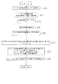
図16の実施例を説明する。先ず被記録材である連続用紙の先頭に位置する1番目の画像フレーム30について、その先端位置を検出し、該先端位置を送り量がゼロの位置に移動する(ステップS1)。画像フレーム30の設定長さYだけ搬送方向の下流に送って停止する(S2)。前記光学式センサ60によって2番目の画像フレーム30との境界に設けられている位置検出マーカMを前記したように検出して1番目の画像フレームの実測長さYcを求める(S3,S4)。該実測長さYcと該画像フレーム30の設定長さYとの差△Yを求め、1番目の画像フレーム30から、これから記録を行う記録画像の長さに対して、前記差△Y分の補正をして(S6)、記録を実行する(S7,S8)。
The embodiment of FIG. 16 will be described. First, the leading edge position of the
図17の実施例を説明する。連続用紙の先頭に位置する1番目の画像フレーム30について、その先端位置を記録開始位置に合わせると共に、これから記録を行う記録画像の長さを設定長さYとして記録を実行する(S10)。1番目の画像フレーム30への前記記録が終了後に該記録終了位置Y1をメモリに記憶する(S11,S12)。前記マーカ検出手段によって2番目の画像フレームとの境界に設けられている位置検出マーカMを検出してそのマーカ検出位置Ycを求める(S13,S14)。これから記録を行う記録画像の長さに対して、前記記録終了位置Y1と前記マーカ検出位置Ycとの差△Y分の補正をして(S15,S16)、記録を実行する(S17)。
The embodiment of FIG. 17 will be described. With respect to the
なお、用紙の先端を記録ヘッドのあるノズル位置に合わせ、その位置を0として、設定長さYだけ紙送りする。また、切り欠きMの中点位置Cを求め、その位置と前記ノズル位置とを合わせる。これにより画像フレーム30の実測長さYcが求まる。
The leading edge of the paper is aligned with the nozzle position where the recording head is located, the position is set to 0, and the paper is fed by the set length Y. Further, the midpoint position C of the notch M is obtained, and the position is matched with the nozzle position. Thereby, the actually measured length Yc of the
本発明によれば、記録エリアを画定する画像フレーム30の長さが、設定長さYと実際の長さYcとが製造バラツキ等の原因で少し違っていても、その影響を受けずに記録エリアに正しく記録を実行することができる。
According to the present invention, the length of the
本発明は、記録エリアを画定する画像フレームが長手方向に複数連なる長尺な被記録材をその長手方向に搬送しつつ前記各記録エリアに記録画像を記録するための記録装置に利用可能である。 INDUSTRIAL APPLICABILITY The present invention can be applied to a recording apparatus for recording a recorded image in each recording area while conveying a long recording material having a plurality of image frames defining a recording area in the longitudinal direction. .
1 二次加工品、 2 給送装置、 3 記録装置本体、 4 ガイド部材、
5 給送用トレイ、10 キャリッジ、11 インクカートリッジ、
12 キャリッジガイド軸、13 記録ヘッド、14 給送用ローラ、
15 エッジガイド、16 ホッパ、17 回転軸、
18 ローラホルダ(搬送用従動ローラの)、19 搬送用ローラ、
19a 搬送用駆動ローラ、19b 搬送用従動ローラ、20 搬出用ローラ、
20a 排出用駆動ローラ、20b 排出用ギザローラ、22 補助ギザローラ、
26 記録部、28 プラテン、30 画像フレーム、31 小フレーム、
32 大フレーム、33 筋押し、34 ミシン目、35 非切断部、36 切断部、40 入口(ロール紙の搬送経路の)、43 カッタ装置、45 ロール紙ホルダ、
47 固定ホルダ、49 可動ホルダ、50 排出用スタッカ、51 載置面、
60 冊子状本体、61 冊子カバー62 接着剤、65 カッタ刃(筋押し用の)、
66 カッタ刃(ミシン目用)、70 非記録エリア、
100 インクジェット式記録装置(記録装置)、 P 用紙(被記録材)、
S 単票紙、 R ロール紙、 Z 連続紙、 X 主走査方向、 Y 副走査方向
1 secondary processed product, 2 feeding device, 3 recording device body, 4 guide member,
5 Feed tray, 10 Carriage, 11 Ink cartridge,
12 Carriage guide shaft, 13 Recording head, 14 Feeding roller,
15 edge guide, 16 hopper, 17 rotation axis,
18 Roller holder (of the driven roller for conveyance), 19 Roller for conveyance,
19a Conveyance drive roller, 19b Conveyance driven roller, 20 Unloading roller,
20a discharge drive roller, 20b discharge roller, 22 auxiliary roller,
26 recording units, 28 platens, 30 image frames, 31 small frames,
32 large frame, 33 muscle push, 34 perforation, 35 non-cutting part, 36 cutting part, 40 entrance (of roll paper transport path), 43 cutter device, 45 roll paper holder,
47 fixed holder, 49 movable holder, 50 discharge stacker, 51 mounting surface,
60 booklet body, 61
66 cutter blade (for perforation), 70 non-recording area,
100 Inkjet recording device (recording device), P paper (recording material),
S cut sheet paper, R roll paper, Z continuous paper, X main scanning direction, Y sub-scanning direction
Claims (6)
被記録材の前記画像フレームの境界位置に対応して配設される位置検出マーカを検出するマーカ検出手段と、
当該被記録材の先頭に位置する1番目の画像フレームについて、その先端位置を検出し、該先端位置を送り量がゼロの位置に移動し、画像フレームの設定長さYだけ搬送方向の下流に送って停止し、前記マーカ検出手段によって2番目の画像フレームとの境界に設けられている位置検出マーカを検出して1番目の画像フレームの実測長さYcを求め、該実測長さYcと該画像フレームの設定長さYとの差△Yを求め、1番目の画像フレームから、これから記録を行う記録画像の長さに対して、前記差△Y分の補正をして記録を実行する制御部と、を備えたことを特徴とする記録装置。 A recording apparatus that performs recording while conveying a long recording material having a plurality of image frames defining a recording area in the longitudinal direction in the longitudinal direction of the recording material,
Marker detection means for detecting a position detection marker disposed corresponding to the boundary position of the image frame of the recording material;
The leading edge position of the first image frame located at the head of the recording material is detected, the leading edge position is moved to a position where the feed amount is zero, and the set length Y of the image frame is downstream in the transport direction. The position detection marker provided at the boundary with the second image frame is detected by the marker detection means to obtain the measured length Yc of the first image frame, and the measured length Yc and the Control for obtaining a difference ΔY from the set length Y of the image frame and performing recording by correcting the difference ΔY for the length of the recorded image to be recorded from the first image frame. A recording apparatus.
被記録材の前記画像フレームの境界位置に対応して配設される位置検出マーカを検出するマーカ検出手段と、
当該被記録材の先頭に位置する1番目の画像フレームについて、その先端位置を記録開始位置に合わせると共にこれから記録を行う記録画像の長さを設定長さYとして記録を実行し、1番目の画像フレームへの前記記録が終了後に該記録終了位置Y1をメモリに記憶し、前記マーカ検出手段によって2番目の画像フレームとの境界に設けられている位置検出マーカを検出してそのマーカ検出位置Ycを求め、これから記録を行う記録画像の長さに対して、前記記録終了位置Y1と前記マーカ検出位置Ycとの差△Y分の補正をして記録を実行する制御部と、を備えたことを特徴とする記録装置。 A recording apparatus that performs recording while conveying a long recording material having a plurality of image frames defining a recording area in the longitudinal direction in the longitudinal direction of the recording material,
Marker detection means for detecting a position detection marker disposed corresponding to the boundary position of the image frame of the recording material;
For the first image frame located at the head of the recording material, the leading edge position is adjusted to the recording start position and recording is performed with the length of the recording image to be recorded as the set length Y. After the recording on the frame is completed, the recording end position Y1 is stored in the memory, the marker detection means detects a position detection marker provided at the boundary with the second image frame, and sets the marker detection position Yc. And a controller that executes recording by correcting the difference ΔY between the recording end position Y1 and the marker detection position Yc with respect to the length of the recorded image to be recorded. A recording apparatus.
Priority Applications (1)
| Application Number | Priority Date | Filing Date | Title |
|---|---|---|---|
| JP2009280310A JP5057117B2 (en) | 2009-12-10 | 2009-12-10 | Recording device |
Applications Claiming Priority (1)
| Application Number | Priority Date | Filing Date | Title |
|---|---|---|---|
| JP2009280310A JP5057117B2 (en) | 2009-12-10 | 2009-12-10 | Recording device |
Related Parent Applications (1)
| Application Number | Title | Priority Date | Filing Date |
|---|---|---|---|
| JP2003345096A Division JP4450166B2 (en) | 2003-10-02 | 2003-10-02 | Recording device |
Publications (2)
| Publication Number | Publication Date |
|---|---|
| JP2010052439A true JP2010052439A (en) | 2010-03-11 |
| JP5057117B2 JP5057117B2 (en) | 2012-10-24 |
Family
ID=42068829
Family Applications (1)
| Application Number | Title | Priority Date | Filing Date |
|---|---|---|---|
| JP2009280310A Expired - Fee Related JP5057117B2 (en) | 2009-12-10 | 2009-12-10 | Recording device |
Country Status (1)
| Country | Link |
|---|---|
| JP (1) | JP5057117B2 (en) |
Families Citing this family (2)
| Publication number | Priority date | Publication date | Assignee | Title |
|---|---|---|---|---|
| KR20110000580A (en) * | 2008-06-25 | 2011-01-03 | 교도 인사쯔 가부시키가이샤 | Moisture indicator and method for producing the same |
| JP2010008118A (en) * | 2008-06-25 | 2010-01-14 | Kyodo Printing Co Ltd | Humidity indicator and its manufacturing method |
Citations (9)
| Publication number | Priority date | Publication date | Assignee | Title |
|---|---|---|---|---|
| JPH02212176A (en) * | 1989-02-14 | 1990-08-23 | Matsushita Electric Ind Co Ltd | Printer |
| JPH05246414A (en) * | 1991-11-13 | 1993-09-24 | Shinsei Ind:Kk | Label printer |
| JPH068675A (en) * | 1992-06-26 | 1994-01-18 | Dainippon Printing Co Ltd | Continuous form |
| JPH0691907A (en) * | 1992-09-09 | 1994-04-05 | Graphtec Corp | Thermal transfer recorder |
| JPH07304219A (en) * | 1994-05-16 | 1995-11-21 | Hitachi Ltd | Portable terminal with function of automatically adjusting printing position |
| JP2000343774A (en) * | 1999-06-03 | 2000-12-12 | Nec Data Terminal Ltd | Method and apparatus for correcting paper feed error |
| JP2001260443A (en) * | 2000-03-22 | 2001-09-25 | Roland Dg Corp | Cutter and method for detecting central position of circular mark |
| JP2002326411A (en) * | 2001-05-07 | 2002-11-12 | Sato Corp | Continuous form printer |
| JP2005111681A (en) * | 2003-10-02 | 2005-04-28 | Seiko Epson Corp | Recording apparatus and material to be recorded |
-
2009
- 2009-12-10 JP JP2009280310A patent/JP5057117B2/en not_active Expired - Fee Related
Patent Citations (9)
| Publication number | Priority date | Publication date | Assignee | Title |
|---|---|---|---|---|
| JPH02212176A (en) * | 1989-02-14 | 1990-08-23 | Matsushita Electric Ind Co Ltd | Printer |
| JPH05246414A (en) * | 1991-11-13 | 1993-09-24 | Shinsei Ind:Kk | Label printer |
| JPH068675A (en) * | 1992-06-26 | 1994-01-18 | Dainippon Printing Co Ltd | Continuous form |
| JPH0691907A (en) * | 1992-09-09 | 1994-04-05 | Graphtec Corp | Thermal transfer recorder |
| JPH07304219A (en) * | 1994-05-16 | 1995-11-21 | Hitachi Ltd | Portable terminal with function of automatically adjusting printing position |
| JP2000343774A (en) * | 1999-06-03 | 2000-12-12 | Nec Data Terminal Ltd | Method and apparatus for correcting paper feed error |
| JP2001260443A (en) * | 2000-03-22 | 2001-09-25 | Roland Dg Corp | Cutter and method for detecting central position of circular mark |
| JP2002326411A (en) * | 2001-05-07 | 2002-11-12 | Sato Corp | Continuous form printer |
| JP2005111681A (en) * | 2003-10-02 | 2005-04-28 | Seiko Epson Corp | Recording apparatus and material to be recorded |
Also Published As
| Publication number | Publication date |
|---|---|
| JP5057117B2 (en) | 2012-10-24 |
Similar Documents
| Publication | Publication Date | Title |
|---|---|---|
| JP5970709B2 (en) | Continuous paper transport control method and printer | |
| JP5014384B2 (en) | Recording apparatus and sheet processing method | |
| EP2233304B1 (en) | Printing system and printing method | |
| US20150375540A1 (en) | Printing apparatus, method of controlling the same, and storage medium | |
| JP4435048B2 (en) | Edge guide, recording apparatus, and liquid ejecting apparatus | |
| JP2007238278A (en) | Recorded medium feeding device, recording device and liquid jetting device | |
| JP5057117B2 (en) | Recording device | |
| JP5057116B2 (en) | Recording device, liquid ejecting device | |
| JP4450165B2 (en) | Recording apparatus and recording material | |
| JP4450166B2 (en) | Recording device | |
| JP2008074581A (en) | Recording medium feeder, recorder, and liquid injection device | |
| JP4192734B2 (en) | Medium conveying apparatus and image forming apparatus having the same | |
| JP4332711B2 (en) | Recording material, liquid injection material, and recording apparatus | |
| JP2002283637A (en) | Device and method for controlling feeding of paper | |
| JP2007098759A (en) | Recorder | |
| JP2007144946A (en) | Recorder and recording control program | |
| JP4141911B2 (en) | Recording material, secondary processed product using recording material, and method of feeding recording material | |
| JP2004292068A (en) | Image forming apparatus | |
| JP5859095B2 (en) | Recording device | |
| JP3891278B2 (en) | Short paper feeding device and recording device provided with the device | |
| JP6344130B2 (en) | Print control apparatus and program | |
| JP2003266377A (en) | Recording device, cut position adjusting pattern, and method for acquiring quantity of cut position slippage | |
| JP4671067B2 (en) | Printing device capable of printing an image on a multi-page cut sheet | |
| JP6102316B2 (en) | Printer and recording paper feed amount correction method | |
| JP2008184270A (en) | Stacker |
Legal Events
| Date | Code | Title | Description |
|---|---|---|---|
| A621 | Written request for application examination |
Free format text: JAPANESE INTERMEDIATE CODE: A621 Effective date: 20091210 |
|
| A131 | Notification of reasons for refusal |
Free format text: JAPANESE INTERMEDIATE CODE: A131 Effective date: 20120125 |
|
| A521 | Written amendment |
Free format text: JAPANESE INTERMEDIATE CODE: A523 Effective date: 20120323 |
|
| A131 | Notification of reasons for refusal |
Free format text: JAPANESE INTERMEDIATE CODE: A131 Effective date: 20120516 |
|
| A521 | Written amendment |
Free format text: JAPANESE INTERMEDIATE CODE: A523 Effective date: 20120531 |
|
| TRDD | Decision of grant or rejection written | ||
| A01 | Written decision to grant a patent or to grant a registration (utility model) |
Free format text: JAPANESE INTERMEDIATE CODE: A01 Effective date: 20120704 |
|
| A01 | Written decision to grant a patent or to grant a registration (utility model) |
Free format text: JAPANESE INTERMEDIATE CODE: A01 |
|
| A61 | First payment of annual fees (during grant procedure) |
Free format text: JAPANESE INTERMEDIATE CODE: A61 Effective date: 20120717 |
|
| FPAY | Renewal fee payment (event date is renewal date of database) |
Free format text: PAYMENT UNTIL: 20150810 Year of fee payment: 3 |
|
| R150 | Certificate of patent or registration of utility model |
Ref document number: 5057117 Country of ref document: JP Free format text: JAPANESE INTERMEDIATE CODE: R150 Free format text: JAPANESE INTERMEDIATE CODE: R150 |
|
| S531 | Written request for registration of change of domicile |
Free format text: JAPANESE INTERMEDIATE CODE: R313531 |
|
| R350 | Written notification of registration of transfer |
Free format text: JAPANESE INTERMEDIATE CODE: R350 |
|
| LAPS | Cancellation because of no payment of annual fees |