JP2010051775A - Differential feed control mechanism of sewing machine - Google Patents
Differential feed control mechanism of sewing machine Download PDFInfo
- Publication number
- JP2010051775A JP2010051775A JP2008258812A JP2008258812A JP2010051775A JP 2010051775 A JP2010051775 A JP 2010051775A JP 2008258812 A JP2008258812 A JP 2008258812A JP 2008258812 A JP2008258812 A JP 2008258812A JP 2010051775 A JP2010051775 A JP 2010051775A
- Authority
- JP
- Japan
- Prior art keywords
- cloth feed
- sewing machine
- component
- control mechanism
- interlocking
- Prior art date
- Legal status (The legal status is an assumption and is not a legal conclusion. Google has not performed a legal analysis and makes no representation as to the accuracy of the status listed.)
- Granted
Links
Images


Classifications
-
- D—TEXTILES; PAPER
- D05—SEWING; EMBROIDERING; TUFTING
- D05B—SEWING
- D05B27/00—Work-feeding means
- D05B27/10—Work-feeding means with rotary circular feed members
- D05B27/16—Work-feeding means with rotary circular feed members with differential feed motions
-
- D—TEXTILES; PAPER
- D05—SEWING; EMBROIDERING; TUFTING
- D05B—SEWING
- D05B33/00—Devices incorporated in sewing machines for supplying or removing the work
-
- D—TEXTILES; PAPER
- D05—SEWING; EMBROIDERING; TUFTING
- D05B—SEWING
- D05B35/00—Work-feeding or -handling elements not otherwise provided for
- D05B35/02—Work-feeding or -handling elements not otherwise provided for for facilitating seaming; Hem-turning elements; Hemmers
-
- D—TEXTILES; PAPER
- D05—SEWING; EMBROIDERING; TUFTING
- D05B—SEWING
- D05B69/00—Driving-gear; Control devices
- D05B69/02—Mechanical drives
-
- D—TEXTILES; PAPER
- D05—SEWING; EMBROIDERING; TUFTING
- D05B—SEWING
- D05B69/00—Driving-gear; Control devices
- D05B69/30—Details
Abstract
Description
本発明は一種のミシンの差動布送り制御機構に係り、特に、ミシンの返し縫い機能があり差動布送り可能な制御機構に関する。 The present invention relates to a kind of differential cloth feed control mechanism for a sewing machine, and more particularly to a control mechanism capable of performing differential cloth feed with a reverse stitching function of a sewing machine.
科学技術の不断の発展と経済水準アップに伴い、人々はますます服飾の快適さと美観を重視するようになり、バッグ、手袋、靴類などの皮革類製品の縫製過程で、多様な複雑な設計に合わせてミシン縫いの方法も改善する必要がある。 With the continuous development of science and technology and the improvement of economic standards, people increasingly attach importance to the comfort and aesthetics of clothing, and in the process of sewing leather products such as bags, gloves and shoes, various complex designs Therefore, it is necessary to improve the sewing method.
現在、差動布送りを実現できるミシンには大きく二種類の布送り方式がある。すなわち、歯式布送りと輪式布送りであり、前者は前送り歯の導入布量が後送り歯の導入布量と同じかそれより多く(いわゆる差動比)、これにより縫製面に平ら或いはギャザーの異なる効果を発生させる。後者は上下の布送り輪とミシン針の組合せにより、上下の布送り輪の相対運動速度を変更し、縫製面に平ら或いはギャザーの異なる効果を発生させる。歯式布送り或いは輪式布送りのいずれもミシンの差動布送りを実現できるが、歯式布送り時の布と送り歯は面接触し、輪式布送りの布と布送り輪は点接触であり、ゆえに輪式布送りを採用した方が、円滑にミシンを操縦でき、これにより理想的な縫製効果と設計効果を達成できる。 Currently, there are two types of cloth feeding systems that can realize differential cloth feeding. In other words, it is a tooth type cloth feed and a ring type cloth feed. In the former, the amount of cloth introduced by the front feed teeth is equal to or larger than the amount of cloth introduced by the rear feed teeth (so-called differential ratio), so that the sewing surface is flattened. Or it produces different effects of gathering. In the latter, the relative movement speed of the upper and lower cloth feed wheels is changed by the combination of the upper and lower cloth feed rings and the sewing needle, and the sewing surface is flat or has different gathering effects. Both the tooth type cloth feed and the ring type cloth feed can realize the differential cloth feed of the sewing machine, but the cloth and the feed dog at the time of the tooth type cloth feed are in surface contact, and the cloth of the ring type cloth feed and the cloth feed wheel are points. Therefore, the one that adopts the ring-type cloth feed can smoothly operate the sewing machine, thereby achieving an ideal sewing effect and design effect.
既存のゲージ輪式布送りは単方向スーパークラッチを採用し、連接棒の円中心の比率に基づいた変更により差動比調節するが、このようなタイプは返し縫い機能がない。このほか、ミシン針を布送り輪と同期させる布送り方式は、ミシン針が布に食い込む状況を発生し、この時、布送り輪がミシン針に対して不同期となり、布送り輪と布の摩擦により布を損傷する不良な効果を発生する。 Existing gauge wheel type cloth feed uses a unidirectional super clutch, and the differential ratio is adjusted by changing the ratio based on the ratio of the center of the connecting rod, but this type does not have a reverse stitching function. In addition, the cloth feed method in which the sewing needle is synchronized with the cloth feed wheel generates a situation in which the sewing needle bites into the cloth. At this time, the cloth feed ring becomes unsynchronized with the sewing needle, and the cloth feed ring and the cloth feed ring are not synchronized. It produces a bad effect of damaging the fabric due to friction.
本発明の目的は、一種の輪式布送りミシンの差動布送り制御機構を提供し、本発明の機構を取付けることで、逆縫いと差動布送りを実現できるようにすることにある。 An object of the present invention is to provide a differential cloth feed control mechanism for a kind of a ring type cloth feed sewing machine, and to provide reverse sewing and differential cloth feed by attaching the mechanism of the present invention.
本発明の目的は以下のように実現される。
ミシンの差動布送り制御機構は、上布送り輪の送り速度を調整するのに用いられ、
往復運動量変更可能な伝動軸による動力伝達をそれぞれが受ける二つの第1揺動部品と第2揺動部品、
該第1揺動部品に枢設された第1連動部品と、該第2揺動部品に枢設された第2連動部品、
該第1連動部品に枢設された第3連動部品と第4連動部品、
該第3連動部品に枢設された第3揺動部品、
該第3揺動部品に接続された調整機構、
径方向カムを具えて該カムの凹溝内に回転子が設けられた入力軸、
二つのクラッチを具え、左クラッチと右クラッチの間に推進リングが設けられ、該推進リングと二つのクラッチの間に位置決めブシュが設けられた布送り軸、
該回転子と該推進リングとに接続された第4揺動部品、
該入力軸と該布送り軸が軸方向に固定されるケース、
以上を包含する。
The object of the present invention is realized as follows.
The differential cloth feed control mechanism of the sewing machine is used to adjust the feed speed of the upper cloth feed wheel,
Two first oscillating parts and second oscillating parts each receiving power transmission by a transmission shaft capable of changing the amount of reciprocating motion;
A first interlocking part pivoted on the first swinging part; a second interlocking part pivoted on the second swinging part;
A third interlocking part and a fourth interlocking part pivoted on the first interlocking part;
A third oscillating component pivoted on the third interlocking component;
An adjustment mechanism connected to the third oscillating component;
An input shaft having a radial cam and a rotor provided in the groove of the cam;
A cloth feed shaft comprising two clutches, a propulsion ring provided between the left clutch and the right clutch, and a positioning bush provided between the propulsion ring and the two clutches;
A fourth swing component connected to the rotor and the propulsion ring;
A case in which the input shaft and the cloth feed shaft are fixed in the axial direction;
Including the above.
上述のミシンの差動布送り制御機構の特徴は、上述の伝動軸と主軸の間に、運動量変更可能な逆縫い装置が設けられ、動力は該主軸より該運動量変更可能な逆縫い装置を介して該伝動軸に伝えられ、該伝動軸より動力を伝達される第5連動部品と第6連動部品がそれぞれクラッチを介して下布送り軸に連接されることにある。 The differential cloth feed control mechanism of the sewing machine described above is characterized in that a reverse stitching device capable of changing the momentum is provided between the transmission shaft and the main shaft, and the power is transmitted from the main shaft via the reverse stitching device capable of changing the momentum. Thus, the fifth interlocking component and the sixth interlocking component transmitted to the transmission shaft and transmitted with power from the transmission shaft are connected to the lower cloth feed shaft via the clutch.
上述のミシンの差動布送り制御機構の特徴は、上述の第5連動部品が第2揺動部品に枢設され、該第6連動部品が該第5揺動部品に枢設され、該第1揺動部品、該第2揺動部品と第5揺動部品がそれぞれその枢設孔により該伝動軸に枢設されたことにある。 The differential cloth feed control mechanism of the sewing machine described above is characterized in that the fifth interlocking component is pivotally mounted on the second swinging component, the sixth interlocking component is pivotally mounted on the fifth swinging component, The first oscillating component, the second oscillating component, and the fifth oscillating component are respectively pivoted on the transmission shaft through the pivot holes.
上述のミシンの差動布送り制御機構の特徴は、該第1揺動部品に枢設孔が設けられ、該第1連動部品に枢設孔が設けられ、ピンがこれらの枢設孔に通されて該第1揺動部品と該第1連動部品が枢設されることにある。 The differential cloth feed control mechanism of the sewing machine described above is characterized in that a pivot hole is provided in the first swing part, a pivot hole is provided in the first interlocking part, and a pin passes through these pivot holes. Thus, the first swinging part and the first interlocking part are pivoted.
上述のミシンの差動布送り制御機構の特徴は、該第3連動部品、該第1連動部品及び該第4連動部品が順にその枢設孔を通過するピンにより枢設され、該第3揺動部品と第3連動部品がその枢設孔を通過するピンにより枢設されることにある。 The differential cloth feed control mechanism of the sewing machine described above is characterized in that the third interlocking component, the first interlocking component, and the fourth interlocking component are pivoted in order by a pin passing through the pivot hole, The moving part and the third interlocking part are pivoted by a pin passing through the pivot hole.
上述のミシンの差動布送り制御機構の特徴は、該第4揺動部品がJ形を呈し、該第4揺動部品がその枢設孔により回転子に接続され、該第4揺動部品は固定孔により該推進リングと固定接続されることにある。 The differential cloth feed control mechanism of the above-described sewing machine is characterized in that the fourth swinging part has a J shape, and the fourth swinging part is connected to the rotor through the pivot hole. Is fixedly connected to the propulsion ring by a fixing hole.
上述のミシンの差動布送り制御機構の特徴は、該調整機構は第3揺動部品に固定された調節ハンドル、調整パネル及び回転つまみを包含し、該回転つまみと調節ハンドルは接続され、該調節ハンドルがネジにより該調整パネルの滑り溝に取付けられることにある。 The above-described differential cloth feed control mechanism of the sewing machine is characterized in that the adjustment mechanism includes an adjustment handle, an adjustment panel, and a rotary knob fixed to the third swing part, and the rotary knob and the adjustment handle are connected to each other. The adjusting handle is attached to the sliding groove of the adjusting panel by screws.
上述のミシンの差動布送り制御機構の特徴は、該調整パネルに縦向きの調整スクリューが通され、該調整パネルに嵌め溝が設けられ、該嵌め溝内に調整ボタンが固定されたことにある。 A characteristic of the above-mentioned sewing machine differential cloth feed control mechanism is that a vertical adjustment screw is passed through the adjustment panel, a fitting groove is provided in the adjustment panel, and an adjustment button is fixed in the fitting groove. is there.
上述のミシンの差動布送り制御機構の特徴は、該入力軸とプーリが接続され、該プーリが同期ベルトを介してもう一つのプーリに連接され、該プーリとミシン主軸が接続されたことにある。 The differential cloth feed control mechanism of the sewing machine described above is characterized in that the input shaft and a pulley are connected, the pulley is connected to another pulley via a synchronous belt, and the pulley and the sewing machine main shaft are connected. is there.
上述のミシンの差動布送り制御機構の特徴は、該布送り軸がスプロケットに接続され、該スプロケットがチェーンを介してもう一つのスプロケットに接続され、該スプロケットがもう一つのチェーンを介して上布送り輪の運動を制御する上布送り軸に接続されたことにある。 The differential cloth feed control mechanism of the sewing machine described above is characterized in that the cloth feed shaft is connected to a sprocket, the sprocket is connected to another sprocket via a chain, and the sprocket is connected to another sprocket via a chain. It is connected to the upper cloth feed shaft that controls the movement of the cloth feed wheel.
本発明のミシンの差動布送り制御機構は往復運動量変更可能な伝動軸に四つ或いは若干の連動部品が接続され、二つの連動部品が一組とされ、一組(第2連動部品と第6連動部品)が同期同速で運動し、もう一組(第4連動部品と第5連動部品)がそのうち一つの連動部品の運動量を変更することにより、この組の連動部品の同期不同速運動を達成し、最終的に上布送り輪に動力伝導し、上布送り輪の運針時の送り量を改変し、こうして以下の効果を達成する。すなわち、ミシン針が布に刺さる時に、上下の布送り輪は同期同速で布送りし、ミシン針が針板上にある第2段布送りの時、上下の布送り輪が差動布送りを実現し、こうして摩擦により布を傷つけることがない。 In the differential cloth feed control mechanism of the sewing machine of the present invention, four or some interlocking parts are connected to a transmission shaft capable of changing the amount of reciprocating motion, and two interlocking parts are made into one set. 6 interlocking parts) move at the same synchronous speed, and another pair (the fourth interlocking part and the fifth interlocking part) changes the momentum of one of the interlocking parts. And finally the power is transmitted to the upper cloth feed wheel, and the feed amount of the upper cloth feed wheel when the needle is moved is modified, thereby achieving the following effects. That is, when the sewing needle pierces the cloth, the upper and lower cloth feed wheels feed the cloth at the same synchronous speed. When the sewing needle is on the second stage cloth feed on the throat plate, the upper and lower cloth feed rings feed the differential cloth feed. Thus, the cloth is not damaged by friction.
本発明は上述の技術手段を採用することにあり、既存の技術に較べて、以下のような長所とプラスの効果を有する。すなわち、本発明の布送りドライバは双方向スーパークラッチを採用し、ゆえに正縫いと逆縫いを実現すると共に、調整機構を調節して上布送り輪の運動量を調節することで、実際の必要に基づき差動布送りの量を制御できる。 The present invention employs the above-described technical means, and has the following advantages and positive effects compared with the existing techniques. That is, the cloth feed driver of the present invention employs a bi-directional super clutch, and thus realizes normal sewing and reverse stitching, and adjusts the momentum of the upper cloth feed wheel by adjusting the adjustment mechanism. Based on this, the amount of differential cloth feed can be controlled.
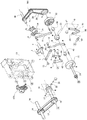
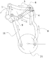
図1及び図2に示されるように、本発明は一種のミシンの差動布送り制御機構であり、それは方形枠形のケース13、ミシンの動力ソースである主軸70、該主軸70は運動量変更可能な逆縫い装置(図示せず。既存技術であるため説明を省略する。)により動力を伝動軸2に送り、ゆえに伝動軸2の往復運動量は変更可能とされ、伝動軸2はまず第1揺動部品1と第2揺動部品9に枢設され、第1揺動部品1に第1連動部品3が枢設され、第2揺動部品9に第2連動部品11が枢設される。第1揺動部品1に枢設孔37が設けられ、第1連動部品3に枢設孔38が設けられ、ピン12がこれら枢設孔37、38に通されて、第1揺動部品1と第1連動部品3が枢設される。第3連動部品4、第1連動部品3及び第4連動部品8はその枢設孔39、40、41によりピン42で枢設され、第3揺動部品6と第3連動部品4はその枢設孔43、44によりピン5で枢設される。
As shown in FIG. 1 and FIG. 2, the present invention is a kind of differential cloth feed control mechanism of a sewing machine, which is a rectangular frame-
第3揺動部品6に調整機構631が接続され、調整機構631は第3揺動部品6に固定された調節ハンドル7、調整パネル401及び回転つまみ411を包含し、該回転つまみ411と調節ハンドル7は固定接続され、該調節ハンドル7がネジ701により該調整パネル401の滑り溝421内に取付けられる。該調整パネル401に縦向きの調整スクリュー431が通され、該調整パネル401に更に嵌め溝441が設けられ、該嵌め溝441内に調整ボタン451が固定される。
An
該ミシンの主軸70にプーリ14が設けられ、該プーリ14が同期ベルト15を介してもう一つのプーリ16に連接され、該もう一つのプーリ16が入力軸17に設けられ、ゆえに主軸70の動力がこのベルトを介して入力軸17に伝えられ、入力軸17が軸方向にケース13の中部に固定され、該入力軸17に更に径方向カム18が設けられ、該カム18の凹溝内に回転子22が設けられる。該ベルトの伝動により、カム18と主軸70が同速回転する。
A
布送り軸10はケース13の下部に固定され、それに二つのクラッチ31、32が設けられ、左クラッチ31と右クラッチ32の間に推進リング23が設けられ、該推進リング23と二つのクラッチ31、32の間に位置決めブシュ45、46が設けられている。第4揺動部品20はJ形を呈し、該第4揺動部品20はその枢設孔47により回転子22に接続され、該第4揺動部品20はまた、固定孔49、50により該推進リング23と固定接続される。また、第4揺動部品20の底部に枢設孔48が設けられ、該枢設孔48内に設けられた偏心ピン85により、該第4揺動部品20がケース13に位置決めされる。径方向カム18の凹溝は第4揺動部品20の動作の必要により設計されて、第4揺動部品20の左右揺動を実現し、第4揺動部品20はまた、推進リング23を駆動して、クラッチ31、32と不断に分離と結合させ、それに以下のような動作効果を達成させる。すなわち、推進リング23と左クラッチ31が結合する時、それと右クラッチ32は必然的に分離する。推進リング23と右クラッチ32が結合するとき、それと左クラッチ31は必然的に分離する。布送り軸10とスプロケット26が接続され、該スプロケット26はチェーン24を介してもう一つのスプロケット501と接続され、このもう一つのスプロケット501はもう一つのチェーン25を介して上布送り輪の運動を制御する上布送り軸80に接続される。
The
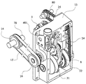
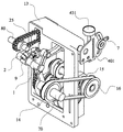
本発明の制御機構の組立完成後の効果は、図3、図4に示されるようである。 The effect after the assembly of the control mechanism of the present invention is as shown in FIGS.
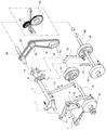
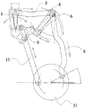
図5、図6に示されるように、主軸70は運動量変更可能な逆縫い装置(図示せず)により伝動軸2に扇形運動させ、伝動軸2により駆動される第5連動部品33と第6連動部品34はそれぞれクラッチ61、62を介して下布送り軸60に接続される。第5連動部品33は第2揺動部品9に枢設され、第6連動部品34は第5揺動部品71に枢設され、第1揺動部品1、第2揺動部品9と第5揺動部品71はそれぞれその枢設孔により伝動軸2に組み合わされる。第1連動部品3と第2連動部品11もそれぞれ第1揺動部品1と第2揺動部品9を通して伝動軸2に枢設され、第2連動部品11と右クラッチ32は接続され、第1連動部品3は第4連動部品8を通して左クラッチ31と接続され、第2揺動部品9は第5連動部品33と第2連動部品11に接続され、第5連動部品33は下布送り軸60上のクラッチ61により下布送り輪64を駆動する。第2連動部品11は布送り軸10に組み合わされたクラッチ32に接続され、伝動軸2の駆動を受ける第6連動部品34は下布送り軸60に組み合わされたクラッチ62に接続される。
As shown in FIGS. 5 and 6, the
図7、図8、図9及び図10は、本発明のミシンの差動布送り制御機構の動作表示図である。第1連動部品3と第3連動部品4は枢設され、第3連動部品4はピン5で第3揺動部品6と枢設され、第3揺動部品6の別端は調節ハンドル7に接続され並びに軸方向でケース13に固定される。これにより調節ハンドル7を回転させることで第3連動部品4が、第1連動部品3が出力する往復動作を受けて行なう運動の円弧の中心を変更でき、調節ハンドル7の角度変更時に、第3連動部品4の円弧の中心が変動し第4連動部品8の行程量の変更が達成される。
7, 8, 9 and 10 are operation display diagrams of the differential cloth feed control mechanism of the sewing machine of the present invention. The
主軸70に組み合わされたプーリ14は同期ベルト15を介して動力をもう一つのプーリ16に伝達し並びに入力軸17を駆動し、径方向カム18を主軸70と同期運動させる。J形の第4揺動部品20は軸21と回転子22を介して径方向カム18に接続され、第4揺動部品40は推進リング23に接続され、径方向カム18の駆動を受けて左右に運動し、クラッチ31、32を主軸70に合わせて運動させ、クラッチ31と32は規律的な離合を形成し、更に第4連動部品8と第2連動部品11の動力が組み合わされて定方向に送られ、更にスプロケット26とチェーン24、25が組み合わされて動力が上布送り軸80に出力され、上布送り軸80が一定の伝動機構を介して最終的に動力を上布送り輪65に伝送する。
The
総合すると、本発明の差動布送り制御機構を有するミシンの第2連動部品11、第4連動部品8、第5連動部品33及び第6連動部品34の動力はいずれも伝動軸2より伝達され、そのうち、第6連動部品34と第2連動部品11の出力は同期同速で、第4連動部品8と第5連動部品33は同期出力で、且つ第4連動部品8は第3連動部品4、第3揺動部品6および調節ハンドル7を通して往復行程量を変更可能であり、こうして4本の連動部品と二組のクラッチ(第4連動部品8に接続されたクラッチ31と第2連動部品11に接続されたクラッチ32が一組とされ、第5連動部品33に接続されたクラッチ61と第6連動部品34に接続されたクラッチ62が一組とされる)の組合せにより、ただ、調節ハンドル7を回して第4連動部品8の行程量を変更することにより、実際の必要によりミシンの上布送り輪65の回転速度を調節し、ミシンの差動布送り目的を達成する。
Overall, the powers of the second interlocking
本発明の好ましい実施例は以上に説明されたが、これは本発明の権利請求範囲を限定するものではなく、本発明に基づきなし得る細部の修飾或いは改変は、いずれも本発明の範囲に属する。 While the preferred embodiment of the present invention has been described above, it is not intended to limit the scope of the invention, and any modification or alteration in detail that may be made based on the invention belongs to the scope of the invention. .
A 入力軸孔
B 布送り軸孔
C 枢設孔
D 連接孔
E 偏心ピン孔
F 調節ハンドル孔
1 第1揺動部品 2 伝動軸
3 第1連動部品 4 第3連動部品
5 ピン 6 第3揺動部品
7 調節ハンドル 8 第4連動部品
9 第2揺動部品 10 布送り軸
11 第2連動部品 12 ピン
13 ケース 14 プーリ
15 同期ベルト 16 プーリ
17 入力軸 18 カム
20 第4揺動部品 21 軸
22 回転子 23 推進リング
24、25 チェーン 26 スプロケット
31、32 クラッチ 33 第5連動部品
34 第6連動部品 37、38 枢設孔
39、40、41 枢設孔 42 ピン
43、44 枢設孔 45、46 位置決めブシュ
47 枢設孔 48 枢設孔
49、50 固定孔 60 下布送り軸
61、62 クラッチ 64 下布送り軸
65 上布送り輪 70 主軸
71 第5揺動部品 80 上布送り軸
85 偏心ピン 401 調整パネル
411 回転つまみ 421 滑り溝
431 調整スクリュー 441 嵌め溝
451 調整ボタン 501 スプロケット
631 調整機構 701 ネジ
A Input shaft hole
B Cloth feed shaft hole C Pivot hole
D Connecting hole E Eccentric pin hole
F Adjustment handle
3 First interlocking
Claims (8)
往復運動量変更可能な伝動軸の動力伝送を受ける第1揺動部品と第2揺動部品と、
該第1揺動部品に枢設された第1連動部品と、該第2揺動部品に枢設された第2連動部品と、
該第1連動部品に枢設された第3連動部品と第4連動部品と、
該第3連動部品に枢設された第3揺動部品と、
該第3揺動部品に接続された調整機構と、
径方向カムが組み合わされて該カムの凹溝内に回転子が設けられた入力軸と、
二つのクラッチを具え、左クラッチと右クラッチの間に推進リングが設けられ、該推進リングと二つのクラッチの間に位置決めブシュが設けられた布送り軸、
該回転子と該推進リングとに接続された第4揺動部品、
該入力軸と該布送り軸が軸方向に固定されるケース、
以上を包含したことを特徴とする、ミシンの差動布送り制御機構。 In the differential cloth feed control mechanism of the sewing machine for adjusting the cloth feed speed of the upper cloth feed wheel,
A first oscillating component and a second oscillating component that receive power transmission of a transmission shaft capable of changing the amount of reciprocating motion;
A first interlocking part pivoted on the first swinging part; a second interlocking part pivoted on the second swinging part;
A third interlocking component and a fourth interlocking component pivoted on the first interlocking component;
A third oscillating component pivoted on the third interlocking component;
An adjustment mechanism connected to the third oscillating component;
An input shaft in which a radial cam is combined and a rotor is provided in the concave groove of the cam;
A cloth feed shaft comprising two clutches, a propulsion ring provided between the left clutch and the right clutch, and a positioning bush provided between the propulsion ring and the two clutches;
A fourth swing component connected to the rotor and the propulsion ring;
A case in which the input shaft and the cloth feed shaft are fixed in the axial direction;
A differential cloth feed control mechanism for a sewing machine including the above.
Applications Claiming Priority (2)
| Application Number | Priority Date | Filing Date | Title |
|---|---|---|---|
| TW097133237 | 2008-08-29 | ||
| TW097133237A TW201009152A (en) | 2008-08-29 | 2008-08-29 | Control mechanism of differential material-feeding for sewing machine |
Publications (2)
| Publication Number | Publication Date |
|---|---|
| JP2010051775A true JP2010051775A (en) | 2010-03-11 |
| JP4795413B2 JP4795413B2 (en) | 2011-10-19 |
Family
ID=41795840
Family Applications (1)
| Application Number | Title | Priority Date | Filing Date |
|---|---|---|---|
| JP2008258812A Expired - Fee Related JP4795413B2 (en) | 2008-08-29 | 2008-10-03 | Differential cloth feed control mechanism of sewing machine |
Country Status (5)
| Country | Link |
|---|---|
| JP (1) | JP4795413B2 (en) |
| KR (1) | KR20100026918A (en) |
| CZ (1) | CZ2009306A3 (en) |
| IT (1) | IT1393794B1 (en) |
| TW (1) | TW201009152A (en) |
Cited By (3)
| Publication number | Priority date | Publication date | Assignee | Title |
|---|---|---|---|---|
| JP2015131102A (en) * | 2014-01-10 | 2015-07-23 | 啓翔股▲ふん▼有限公司 | Differential cloth feeding device of sewing machine |
| CN109402877A (en) * | 2018-11-23 | 2019-03-01 | 浙江乐江机械有限公司 | A kind of work feed adjustment mechanism of sewing machine |
| CN111394893A (en) * | 2020-05-22 | 2020-07-10 | 杰克缝纫机股份有限公司 | Cloth feeding mechanism with adjustable cloth feeding time sequence and sewing machine |
Families Citing this family (4)
| Publication number | Priority date | Publication date | Assignee | Title |
|---|---|---|---|---|
| TW201506220A (en) * | 2013-08-14 | 2015-02-16 | Chee Siang Co Ltd | Material delivering device of sewing machine |
| CN104775237B (en) * | 2014-01-14 | 2017-04-12 | 启翔股份有限公司 | differential feeding device of sewing machine |
| CN106498632B (en) * | 2016-12-31 | 2019-07-09 | 杰克缝纫机股份有限公司 | A kind of sewing machine with synchronization feeding device |
| CN106676764A (en) * | 2016-12-31 | 2017-05-17 | 杰克缝纫机股份有限公司 | Rear tug device and sewing machine |
Citations (10)
| Publication number | Priority date | Publication date | Assignee | Title |
|---|---|---|---|---|
| US3141428A (en) * | 1961-05-25 | 1964-07-21 | Pfaff Ag G M | Wheel-feed mechanism for sewing machines |
| JPS5611772U (en) * | 1979-07-04 | 1981-01-31 | ||
| JPS57194477U (en) * | 1981-06-02 | 1982-12-09 | ||
| JPS58173582A (en) * | 1982-03-25 | 1983-10-12 | コツホス・アドラ−・アクチエンゲゼルシヤフト | Sending transmission apparatus of sewing machine |
| JPS63139593A (en) * | 1986-11-29 | 1988-06-11 | ジューキ株式会社 | Work feeder of sewing machine |
| JPH07167170A (en) * | 1993-12-13 | 1995-07-04 | Juki Corp | Reversible clutch |
| JPH0966183A (en) * | 1995-09-01 | 1997-03-11 | Yamato Sewing Mach Co Ltd | Looper thread reeling device |
| JP2003079982A (en) * | 2001-09-17 | 2003-03-18 | Yamato Sewing Mach Co Ltd | Sewing machine |
| JP2006305213A (en) * | 2005-05-02 | 2006-11-09 | Morimoto Mfg Co Ltd | Feeding device for sewing machine |
| JP2009148529A (en) * | 2008-01-16 | 2009-07-09 | Chee Siang Industrial Co Ltd | Clutch structure for sewing machine |
-
2008
- 2008-08-29 TW TW097133237A patent/TW201009152A/en not_active IP Right Cessation
- 2008-10-03 JP JP2008258812A patent/JP4795413B2/en not_active Expired - Fee Related
- 2008-10-31 KR KR1020080108035A patent/KR20100026918A/en not_active Application Discontinuation
-
2009
- 2009-04-03 IT ITVE2009A000020A patent/IT1393794B1/en active
- 2009-05-14 CZ CZ20090306A patent/CZ2009306A3/en unknown
Patent Citations (10)
| Publication number | Priority date | Publication date | Assignee | Title |
|---|---|---|---|---|
| US3141428A (en) * | 1961-05-25 | 1964-07-21 | Pfaff Ag G M | Wheel-feed mechanism for sewing machines |
| JPS5611772U (en) * | 1979-07-04 | 1981-01-31 | ||
| JPS57194477U (en) * | 1981-06-02 | 1982-12-09 | ||
| JPS58173582A (en) * | 1982-03-25 | 1983-10-12 | コツホス・アドラ−・アクチエンゲゼルシヤフト | Sending transmission apparatus of sewing machine |
| JPS63139593A (en) * | 1986-11-29 | 1988-06-11 | ジューキ株式会社 | Work feeder of sewing machine |
| JPH07167170A (en) * | 1993-12-13 | 1995-07-04 | Juki Corp | Reversible clutch |
| JPH0966183A (en) * | 1995-09-01 | 1997-03-11 | Yamato Sewing Mach Co Ltd | Looper thread reeling device |
| JP2003079982A (en) * | 2001-09-17 | 2003-03-18 | Yamato Sewing Mach Co Ltd | Sewing machine |
| JP2006305213A (en) * | 2005-05-02 | 2006-11-09 | Morimoto Mfg Co Ltd | Feeding device for sewing machine |
| JP2009148529A (en) * | 2008-01-16 | 2009-07-09 | Chee Siang Industrial Co Ltd | Clutch structure for sewing machine |
Cited By (5)
| Publication number | Priority date | Publication date | Assignee | Title |
|---|---|---|---|---|
| JP2015131102A (en) * | 2014-01-10 | 2015-07-23 | 啓翔股▲ふん▼有限公司 | Differential cloth feeding device of sewing machine |
| CN109402877A (en) * | 2018-11-23 | 2019-03-01 | 浙江乐江机械有限公司 | A kind of work feed adjustment mechanism of sewing machine |
| CN109402877B (en) * | 2018-11-23 | 2024-02-09 | 浙江乐江机械有限公司 | Cloth feeding adjusting mechanism of sewing machine |
| CN111394893A (en) * | 2020-05-22 | 2020-07-10 | 杰克缝纫机股份有限公司 | Cloth feeding mechanism with adjustable cloth feeding time sequence and sewing machine |
| CN111394893B (en) * | 2020-05-22 | 2021-04-20 | 杰克缝纫机股份有限公司 | Cloth feeding mechanism with adjustable cloth feeding time sequence and sewing machine |
Also Published As
| Publication number | Publication date |
|---|---|
| CZ2009306A3 (en) | 2010-03-10 |
| ITVE20090020A1 (en) | 2010-02-28 |
| IT1393794B1 (en) | 2012-05-08 |
| KR20100026918A (en) | 2010-03-10 |
| TWI340776B (en) | 2011-04-21 |
| JP4795413B2 (en) | 2011-10-19 |
| TW201009152A (en) | 2010-03-01 |
Similar Documents
| Publication | Publication Date | Title |
|---|---|---|
| JP4795413B2 (en) | Differential cloth feed control mechanism of sewing machine | |
| CN203513991U (en) | Needle pitch transforming mechanism of sewing machine | |
| CN104593952B (en) | Three-dimensional feeding sewing machine | |
| TWI506173B (en) | Sewing machine differential feeding device | |
| JP3178831U (en) | Sewing machine feed mechanism | |
| CN201245757Y (en) | Control mechanism for differential feed of sewing machine | |
| JP3153594U (en) | Sewing machine differential cloth feeder | |
| TWM477469U (en) | Differential feeding device of sewing machine | |
| CN101381931B (en) | Differential feed controlling mechanism for sewing machine | |
| CN109402877A (en) | A kind of work feed adjustment mechanism of sewing machine | |
| JP2007111170A (en) | Front/rear feed dog differential feeding mechanism in cylinder bed type sewing machine | |
| CN205636056U (en) | Sewing machine's work feed tooth feeding device | |
| CN201245765Y (en) | Switching mechanism for feed part of two-needle sewing machine | |
| CN203451812U (en) | Backstitching and clockwise stitching switching device in sewing machine | |
| CN101314901B (en) | Switch-over mechanism of feeding section of two-needle sewing machine | |
| CN206052316U (en) | The separate sewing machine of a kind of lift tooth and feeding | |
| CN205556998U (en) | Domestic sewing machine's tailor gauge needle adjusts structure | |
| CN205934320U (en) | Linking machine transmission system | |
| CN216107507U (en) | Sewing machine | |
| TWI802112B (en) | Cylindrical machine yarn guide disc transmission mechanism | |
| CN115247320B (en) | Adjusting mechanism and sewing machine | |
| CN219908081U (en) | Auxiliary mounting mechanism of sewing machine | |
| TWI796518B (en) | Feeding mechanism of sewing machine | |
| JP3092151U (en) | Sewing machine with front differential feed adjustment control mechanism | |
| CN202090162U (en) | Improved feed structure of sewing machine |
Legal Events
| Date | Code | Title | Description |
|---|---|---|---|
| A977 | Report on retrieval |
Free format text: JAPANESE INTERMEDIATE CODE: A971007 Effective date: 20110126 |
|
| A131 | Notification of reasons for refusal |
Free format text: JAPANESE INTERMEDIATE CODE: A131 Effective date: 20110201 |
|
| A521 | Written amendment |
Free format text: JAPANESE INTERMEDIATE CODE: A523 Effective date: 20110426 |
|
| TRDD | Decision of grant or rejection written | ||
| A01 | Written decision to grant a patent or to grant a registration (utility model) |
Free format text: JAPANESE INTERMEDIATE CODE: A01 Effective date: 20110705 |
|
| A01 | Written decision to grant a patent or to grant a registration (utility model) |
Free format text: JAPANESE INTERMEDIATE CODE: A01 |
|
| A61 | First payment of annual fees (during grant procedure) |
Free format text: JAPANESE INTERMEDIATE CODE: A61 Effective date: 20110727 |
|
| R150 | Certificate of patent or registration of utility model |
Free format text: JAPANESE INTERMEDIATE CODE: R150 |
|
| FPAY | Renewal fee payment (event date is renewal date of database) |
Free format text: PAYMENT UNTIL: 20140805 Year of fee payment: 3 |
|
| LAPS | Cancellation because of no payment of annual fees |