JP2010051607A - Lower runner of umbrella - Google Patents

Lower runner of umbrella Download PDF

Info

Publication number
JP2010051607A
JP2010051607A JP2008220644A JP2008220644A JP2010051607A JP 2010051607 A JP2010051607 A JP 2010051607A JP 2008220644 A JP2008220644 A JP 2008220644A JP 2008220644 A JP2008220644 A JP 2008220644A JP 2010051607 A JP2010051607 A JP 2010051607A
Authority
JP
Japan
Prior art keywords
slit
umbrella
main body
repelling
tube wall
Prior art date
Legal status (The legal status is an assumption and is not a legal conclusion. Google has not performed a legal analysis and makes no representation as to the accuracy of the status listed.)
Granted
Application number
JP2008220644A
Other languages
Japanese (ja)
Other versions
JP5270262B2 (en
JP2010051607A5 (en
Inventor
Kazuo Harasawa
一雄 原澤
Current Assignee (The listed assignees may be inaccurate. Google has not performed a legal analysis and makes no representation or warranty as to the accuracy of the list.)
Individual
Original Assignee
Individual
Priority date (The priority date is an assumption and is not a legal conclusion. Google has not performed a legal analysis and makes no representation as to the accuracy of the date listed.)
Filing date
Publication date
Application filed by Individual filed Critical Individual
Priority to JP2008220644A priority Critical patent/JP5270262B2/en
Publication of JP2010051607A publication Critical patent/JP2010051607A/en
Publication of JP2010051607A5 publication Critical patent/JP2010051607A5/ja
Application granted granted Critical
Publication of JP5270262B2 publication Critical patent/JP5270262B2/en
Expired - Fee Related legal-status Critical Current
Anticipated expiration legal-status Critical

Links

Images

Abstract

<P>PROBLEM TO BE SOLVED: To safely close an umbrella without hurting hands. <P>SOLUTION: A body 18 of a lower runner 8 is provided with a slit 30 for releasing a top spring 14 formed on a shaft of the umbrella in the direction projecting out through a tube wall 28 of the body 18, and the slit 30 forms a locking plane 8a for the top spring 14 in the tube wall 28 of the body. A guard part 24 is attached to the tube wall 28 of the body 18, and is formed with a long and thin operation tab 26 for the top spring so that it faces approximately parallel to the slit 30 with predetermined spacing. The operation tab 26 is made crooked inward of the body 18, and then, the top projecting part 14a of the top spring 14 projecting out through the slit 30 can be pushed in the direction for being released from the locking plane 8a. <P>COPYRIGHT: (C)2010,JPO&INPIT

Description

本発明は、手を傷めることなく傘を安全に閉じることができるようにした傘の下ろくろに関する。   The present invention relates to an umbrella handle that can be safely closed without damaging the hand.

従来、傘を安全に開閉できるようにした種々の下ろくろが開発されている(例えば特許文献1,2参照)。
特開2001−104030号公報 特開平11−56432号公報
Conventionally, various armpits have been developed that allow the umbrella to be opened and closed safely (see, for example, Patent Documents 1 and 2).
JP 2001-104030 A Japanese Patent Laid-Open No. 11-56432

これらの従来技術は、いずれも上はじきを直接指の腹で押して、下ろくろに対するロックを解除するものである。しかるに、上はじきは薄い鉄片により構成され、ばね圧によって下ろくろとのロックを解除しにくくなっているため、これを強く指の腹で押すと手を傷めてしまうという問題点がある。
また本願出願人は、はじきに相当する金属製の係止片を把手を介して押す構成とした下ろくろを開発したが(特願2006−332926号)、係止片を下ろくろ側に配設する構造をとるため、下ろくろの構造が複雑になってしまうという問題点がある。
本発明は上記問題点を解決することを目的とするものである。
In each of these prior arts, the upper flip is pushed directly with the belly of the finger to release the lock on the bottom rail. However, the upper pallet is made of a thin iron piece, and it is difficult to release the lock on the bottom with the spring pressure, so that there is a problem that the hand is hurt if it is strongly pressed with the belly of the finger.
In addition, the applicant of the present application has developed a bottom roller configured to push a metal locking piece corresponding to a flip through a handle (Japanese Patent Application No. 2006-332926), but the locking piece is disposed on the bottom side. Therefore, there is a problem that the bottom structure becomes complicated.
The present invention aims to solve the above problems.

上記目的を達成するため本発明は、筒状の本体18に形成された連結部16が傘の骨部分12に連結し、該筒状の本体18を傘のシャフト部分に沿ってスライドさせて、傘の開閉を行うための下ろくろであって、前記シャフト部分に設けられた上はじき14を前記本体18の管璧28から突出する方向に開放するための前記本体18の管璧28に形成されたスリット30と、前記スリット30から突出する上はじき14の外側突出部14aの石突側の端面を係止するための前記本体の管璧28に形成された係止面8aと、前記スリット30の傘柄側の端部に隣接して前記本体18の管璧28に設けられた鍔部24と、前記スリット30に所定の間隔を存して略平行に対面するように前記鍔部24に揺動自在に形成された細長状の上はじき用操作片26とを備え、前記操作片26を前記本体18の内側方向に屈曲させて前記スリット30から突出する上はじき14の上側突出部14aを前記係止面8aから外れる方向に押し込むことができるようにしたものである。
また本発明は、前記上はじき用操作片26を可撓弾力性を有する部材により構成したものである。
また本発明は、前記スリット30の他に、前記本体18の管璧28に、下はじき用のスリットを設け、該スリットの傘柄側の端部に位置して、前記本体18の管璧28に前記シャフト部分に設けた下はじきと係合するための係止面を設けたものである。
また本発明は、筒状の本体18に形成された連結部16が傘の骨部分12に連結し、該筒状の本体18を傘のシャフト部分に沿ってスライドさせて、傘の開閉を行うための下ろくろであって、前記シャフト部分に設けられた上はじき14を前記本体18の管璧28から突出する方向に開放するための前記本体18の管璧28に形成されたスリット30と、前記スリット30から突出する上はじき14の外側突出部14aの石突側の端面を係止するための前記本体の管璧28に形成された係止面8aと、前記スリット30の傘柄側の端部に隣接して前記本体18の管璧28に設けられた鍔部24と、前記スリット30に所定の間隔を存して略平行に対面するように前記鍔部24に揺動自在に形成された細長状の上はじき用操作片26とを備え、前記操作片26を前記本体18の内側方向に屈曲させて前記スリット30から突出する上はじき14の上側突出部14aを前記係止面8aから外れる方向に押し込むことができるようにし、前記スリット30の傘柄側の端部に位置して、前記本体18の管璧28に前記シャフト部分に設けた下はじきと係合するための係止面40を設け、前記上はじき用操作片26にU字状にスリットを設けてU字状の下はじき用操作片38を揺動自在に形成し、該下はじき用操作片38を前記本体18の内側方向に屈曲させて前記スリット30から突出する下はじき34の外側突出部34aを前記下はじき用係止面40から外れる方向に押し込むことができるようにしたものである。
In order to achieve the above object, according to the present invention, the connecting portion 16 formed on the cylindrical main body 18 is connected to the bone portion 12 of the umbrella, and the cylindrical main body 18 is slid along the shaft portion of the umbrella, An opening for opening and closing the umbrella, which is formed on the pipe wall 28 of the main body 18 for opening the upper repelling 14 provided on the shaft portion in a direction protruding from the pipe wall 28 of the main body 18. A slit 30, a locking surface 8 a formed on the tube wall 28 of the main body for locking the end surface of the outer protrusion 14 a of the upper repelling 14 protruding from the slit 30, and the slit 30 The flange 24 provided on the pipe wall 28 of the main body 18 adjacent to the end portion on the umbrella handle side and the flange 24 so as to face the slit 30 at a predetermined interval and substantially parallel to each other. Slippery upper repellent operation formed freely The upper projecting portion 14a of the upper repelling 14 projecting from the slit 30 can be pushed in a direction away from the locking surface 8a. It is a thing.
In the present invention, the upper repelling operation piece 26 is formed of a member having flexibility.
Further, in the present invention, in addition to the slit 30, the pipe wall 28 of the main body 18 is provided with a slit for lower repelling, and the pipe wall 28 of the main body 18 is positioned at the end of the slit on the umbrella pattern side. In addition, a locking surface for engaging with a lower flip provided on the shaft portion is provided.
Further, according to the present invention, the connecting portion 16 formed on the cylindrical main body 18 is connected to the bone portion 12 of the umbrella, and the cylindrical main body 18 is slid along the shaft portion of the umbrella to open and close the umbrella. A slit 30 formed in the pipe wall 28 of the main body 18 for opening the upper repelling 14 provided on the shaft portion in a direction protruding from the pipe wall 28 of the main body 18; A locking surface 8a formed on the tube wall 28 of the main body for locking the end surface of the outer protruding portion 14a of the upper repelling 14 protruding from the slit 30, and an end of the slit 30 on the umbrella handle side A flange 24 provided on the pipe wall 28 of the main body 18 adjacent to the flange and a flange 24 formed so as to be swingable so as to face the slit 30 substantially parallel with a predetermined interval. A strip-like upper repelling operation piece 26, The operation piece 26 is bent in the inner direction of the main body 18 so that the upper protruding portion 14a of the upper repelling 14 protruding from the slit 30 can be pushed in a direction away from the locking surface 8a. A locking surface 40 is provided on the tube wall 28 of the main body 18 to be engaged with a lower repel provided on the shaft portion, and a U-shape is formed on the upper repelling operation piece 26. A U-shaped lower repelling operation piece 38 is formed so as to be swingable, and the lower repelling operation piece 38 is bent inwardly of the main body 18 and protrudes from the slit 30. The outer projecting portion 34 a of 34 can be pushed in a direction away from the lower-flip engagement surface 40.

本発明は上述の如く構成したので、指を傷めることなく安全に傘を閉じることができる。   Since the present invention is configured as described above, the umbrella can be safely closed without damaging the finger.

以下に本発明の実施の形態を添付した図面を参照して詳細に説明する。
図4は、折り畳み式洋傘のシャフト部分と、骨組み部分の一部を示す説明図であり、傘を開いた状態を示している。シャフト部分2は、3本のシャフトからなり、傘柄が取り付けられた一番太い下部シャフト(図示省略)には、中間スライドシャフト4がスライド自在に嵌挿配置され、該スライドシャフト4に上部スライドシャフト6がスライド自在に嵌挿配置されている。
Embodiments of the present invention will be described below in detail with reference to the accompanying drawings.
FIG. 4 is an explanatory view showing a shaft portion of a foldable western umbrella and a part of a skeleton portion, and shows a state in which the umbrella is opened. The shaft portion 2 includes three shafts, and an intermediate slide shaft 4 is slidably inserted into the thickest lower shaft (not shown) to which an umbrella pattern is attached. The shaft 6 is slidably inserted and arranged.

前記シャフト部分2には、下ろくろ8がスライド可能に嵌挿配置されている。前記上部スライドシャフト6の上端には、石突が固設された上ろくろ10が固設されている。前記上部スライドシャフト6の上部の所定の位置には上はじき14が内蔵され、該上はじき14は、その上側突出部14aが、前記スライドシャフト6の管璧に形成されたスリットから外部に弾発的に突出している。 On the shaft portion 2, a bottom wheel 8 is slidably inserted and arranged. On the upper end of the upper slide shaft 6, an upper ladle 10 having a stone protrusion is fixed. An upper repelling 14 is built in a predetermined position on the upper slide shaft 6, and the upper repelling 14 has an upper protruding portion 14 a that is elastically projected from a slit formed in the tubular wall of the slide shaft 6. Protruding.

前記上はじき14は、金属板により構成され、外側突出部14aにシャフト6に対して直角方向に延びるストッパー部14bが形成されている。上はじき14は、その外側突出部14aを押圧することにより、シャフト6から引っ込む方向に揺動させることができるように構成されている。この上はじき14の構成は、従来公知であるためその詳細な説明を省略する。 The upper repellency 14 is made of a metal plate, and a stopper portion 14b extending in a direction perpendicular to the shaft 6 is formed on the outer protruding portion 14a. The upper repellency 14 is configured to be able to swing in the direction of retracting from the shaft 6 by pressing the outer protrusion 14a. Further, since the structure of the repellent 14 is conventionally known, its detailed description is omitted.

前記下部シャフトと、スライドシャフト4,6から成るシャフト部分2は全体として伸縮自在な入れ子式のいわゆる中棒を構成している。前記シャフト部分2は、3本のシャフトが互いに相対回転しないように、互いに回転防止機構(図示省略)を介して嵌合し、3本のシャフトは軸方向にのみ互いにスライド自在に嵌合している。 The lower shaft and the shaft portion 2 composed of the slide shafts 4 and 6 constitute a so-called middle rod that can be expanded and contracted as a whole. The shaft portion 2 is fitted to each other via an anti-rotation mechanism (not shown) so that the three shafts do not rotate relative to each other, and the three shafts are slidably fitted to each other only in the axial direction. Yes.

前記上ろくろ10と下ろくろ8には、折り畳み自在な骨部分12が結合している。シャフト部分2を伸ばし、下ろくろ8を、シャフト部分2に沿って先端(石突)方向に移動させると、図4に示すように、骨部分12が、下ろくろ8の移動に伴って開く。下ろくろ8は、シャフト部分2に設けられたストッパー15(図2参照)に係止される位置まで移動すると、連結部16の下側に位置して、前記下ろくろ8に形成された係止面8aが上はじき14によって解除可能に係止されるように構成されている。 A foldable bone portion 12 is coupled to the upper and lower skulls 10 and 8. When the shaft portion 2 is stretched and the lower skull 8 is moved along the shaft portion 2 in the tip (stone bump) direction, the bone portion 12 is opened along with the movement of the lower skull 8 as shown in FIG. When the bottom wheel 8 moves to a position where it is locked by a stopper 15 (see FIG. 2) provided on the shaft portion 2, the bottom wheel 8 is positioned below the connecting portion 16 and is formed on the bottom wheel 8. The surface 8 a is configured to be releasably locked by the upper repellent 14.

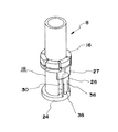
図1乃至図3は、本発明の第1の実施形態の下ろくろ8の構造を示している。下ろくろ8の本体18は、合成樹脂の筒体により構成され、中空部20がシャフト部分2にスライド自在に遊嵌している。本体18の中間部には、フランジ状に連結部16が形成され、該連結部16の外周面に形成された凹溝部22には、骨部分12の受骨12aの各一端が枢支され、下ろくろ8は、受骨12aとの結合によって、シャフト部分2に対して、回転方向の移動が規制されている。   1 to 3 show the structure of the scissors 8 according to the first embodiment of the present invention. The main body 18 of the lower wheel 8 is formed of a synthetic resin cylinder, and the hollow portion 20 is slidably fitted to the shaft portion 2. A connecting portion 16 is formed in a flange shape at an intermediate portion of the main body 18, and each end of the receiving bone 12 a of the bone portion 12 is pivotally supported by the recessed groove portion 22 formed on the outer peripheral surface of the connecting portion 16. The movement of the lower wheel 8 with respect to the shaft portion 2 is restricted by the coupling with the receiving bone 12a.

前記連結部16の、傘柄側の端部には、下ろくろ8の軸方向に対して垂直な係止面8aが形成されている。前記本体18の、傘柄側の端部には、前記連結部16との間に、前記上はじき14の外側突出部14aの全長と略同一の長さの間隔を存して、鍔部24が一体的に形成され、該鍔部24の外径部に、前記連結部16側に延びる、弾力性と可撓性を有する、操作片26が一体的に、本体18の軸方向に沿って、形成されている。 At the end of the connecting portion 16 on the umbrella handle side, a locking surface 8a perpendicular to the axial direction of the bottom pole 8 is formed. At the end of the main body 18 on the umbrella handle side, there is an interval of approximately the same length as the entire length of the outer protruding portion 14a of the upper repellant 14 between the connecting portion 16 and the flange portion 24. Are integrally formed, and an operation piece 26 having elasticity and flexibility, which extends toward the connecting portion 16 side, is integrally formed along the axial direction of the main body 18 on the outer diameter portion of the flange portion 24. Is formed.

前記操作片26の上部開放端側は、連結部16に一体的に形成された薄板状のカバー片27とこれに対して内側に位置して平行に対向している。このカバー片27は、操作片26が外方に跳ね上がるのを防止している。前記本体18の、前記連結部16と鍔部24との間の筒状部の管璧28には、上はじき14の外側突出部14aを管璧28から開放する所定の幅のスリット30が形成されている。 The upper open end side of the operation piece 26 is opposed to and parallel to a thin plate-like cover piece 27 formed integrally with the connecting portion 16. The cover piece 27 prevents the operation piece 26 from jumping outward. A slit 30 having a predetermined width that opens the outer protruding portion 14a of the upper repellency 14 from the tube wall 28 is formed in the tube wall 28 of the cylindrical portion between the connecting portion 16 and the flange portion 24 of the main body 18. Has been.

前記スリット30の横幅は、本実施形態では、管璧28を円周方向に略90度切欠した範囲に設定されている。前記スリット30の上端面は、前記連結部16の下面と同一面上に形成され、該下面とともに、係止面8aを構成している。前記操作片26の先端は、前記連結部16の係止面8aを有する下部端面と所定の間隔を存して対向し、該操作片26は、前記鍔部24から、前記スリット30に対して所定の間隔を存して、平行に延びている。 In this embodiment, the lateral width of the slit 30 is set to a range in which the tube wall 28 is cut out by approximately 90 degrees in the circumferential direction. The upper end surface of the slit 30 is formed on the same surface as the lower surface of the connecting portion 16, and constitutes a locking surface 8a together with the lower surface. The distal end of the operation piece 26 is opposed to the lower end surface having the locking surface 8a of the connecting portion 16 with a predetermined interval, and the operation piece 26 is directed from the flange portion 24 to the slit 30. It extends in parallel at a predetermined interval.

前記操作片26の横幅は、前記上はじき14の外側突出部14aの厚みよりも広く設定され、且つ、前記スリット30の横幅よりも狭く設定されている。前記操作片26は、下ろくろ8の係止面8aが、図2に示すように、上はじき14によって下方向の移動が係止された状態において、上はじき14の外側突出部14aに対向している。 The lateral width of the operation piece 26 is set wider than the thickness of the outer protrusion 14 a of the upper repellent 14, and is narrower than the lateral width of the slit 30. As shown in FIG. 2, the operation piece 26 faces the outer protruding portion 14 a of the upper flip 14 in a state in which the downward movement is locked by the upper flip 14 as shown in FIG. 2. ing.

上記した構成において、傘が閉じた状態では、下ろくろ8は、上はじき14の下方に位置している。傘を開くときは、シャフト部分2を伸ばし、下ろくろ8をシャフト部分2に沿って先端の石突方向に、手操作により、骨部分12からの弾発力に抗して、移動させる。この移動中、下ろくろ8が上はじき14を通過するときは、上はじき14は、下ろくろ8の中空部20の内周面により、シャフト部分2の内側方向に押圧され、外側突出部14aが、ばね力に抗してシャフト部分2の内側方向に引っ込む。   In the above-described configuration, when the umbrella is closed, the bottom pole 8 is positioned below the top flip 14. When the umbrella is opened, the shaft portion 2 is extended, and the bottom wheel 8 is moved along the shaft portion 2 in the direction of the tip of the tip against the elastic force from the bone portion 12 by manual operation. During the movement, when the lower wheel 8 passes through the upper repellent 14, the upper repellent 14 is pressed toward the inside of the shaft portion 2 by the inner peripheral surface of the hollow portion 20 of the lower crossing 8, and the outer protruding portion 14a is Then, the shaft portion 2 is retracted against the spring force.

更に下ろくろ8がストッパー15に衝突する位置まで移動すると、下ろくろ8のスリット30が上はじき14の外側突出部14aの直上に移動する。スリット30が上はじき14の外側突出部14aに移動すると、図2に示すように、上はじき14は、下ろくろ8からの押圧力から開放され、外側突出部14aが、シャフト部分2の内部から、ばね力により外側に突出し、外側突出部14aのストッパー部14bが、下ろくろ8の係止面8aと対面する。 When the bottom wheel 8 further moves to a position where it collides with the stopper 15, the slit 30 of the bottom wheel 8 moves directly above the outer protrusion 14 a of the top repellent 14. When the slit 30 moves to the outer protruding portion 14a of the upper repellent 14, as shown in FIG. 2, the upper repelling 14 is released from the pressing force from the lower wheel 8, and the outer protruding portion 14a is released from the inside of the shaft portion 2. The stopper portion 14b of the outer protruding portion 14a faces the locking surface 8a of the bottom rail 8 due to the spring force.

これにより、下ろくろ8は、上はじき14により、シャフト部分2に沿った下方向の移動が阻止され、下ろくろ8は、上部スライドシャフト6の先端側の所定位置に係止される。下ろくろ8が上はじき14に係止された状態において、図4に示すように、傘が開いた状態となる。傘を閉じたいときは、操作片26を指の腹で押し、これを屈曲させて上はじき14を図3に示すように、シャフト部分2の内側方向に押し込む。 As a result, the lower wheel 8 is prevented from moving downward along the shaft portion 2 by the upper repelling 14, and the lower wheel 8 is locked at a predetermined position on the tip side of the upper slide shaft 6. In the state where the lower wheel 8 is locked to the upper flip 14, the umbrella is opened as shown in FIG. When it is desired to close the umbrella, the operation piece 26 is pushed by the belly of the finger, bent, and the upper repelling 14 is pushed inwardly of the shaft portion 2 as shown in FIG.

これにより、上はじき14の下ろくろ8に対する係止が外れ、下ろくろ8は自由にシャフト部分2に沿って傘柄方向にスライド自在となる。該状態において、下ろくろ8をシャフト部分2に沿って、傘柄側にスライドさせ、傘を閉じ、且つシャフト部分2を短縮させる。 As a result, the upper peg 14 is unlocked from the lower peg 8, and the lower peg 8 can freely slide along the shaft portion 2 in the direction of the umbrella pattern. In this state, the bottom wheel 8 is slid along the shaft portion 2 toward the umbrella handle, the umbrella is closed, and the shaft portion 2 is shortened.

尚、本実施形態では、伸縮型のシャフト部分2に下はじきを設けていないが、下はじきを上はじき14に対して円周方向にずらして設けても良い。この場合には、この下はじき用のスリットを図1に示すスリット30に隣接して、本体18の管璧28に設ける。この場合、管璧28には下はじき用スリットによって、下はじきの下端と係合する係止面(図示省略)が形成される。この下はじき用のスリットの構造は一般的な構成であるためその図示及び説明を省略する。   In the present embodiment, the telescopic shaft portion 2 is not provided with a lower repellency, but the lower repellency may be provided by being shifted in the circumferential direction with respect to the upper repellency 14. In this case, the lower repelling slit is provided in the tube wall 28 of the main body 18 adjacent to the slit 30 shown in FIG. In this case, the pipe wall 28 is formed with a locking surface (not shown) that engages with the lower end of the lower repellant by the lower repellant slit. The structure of the slit for repelling under this is a general structure, and its illustration and description are omitted.

下はじきを指の腹で押し、下はじきによる下ろくろ8に対する係止を解除する動作は比較的弱い押圧力で行うことができるので、下ろくろ8に下はじき用の操作片を特に設けなくても良い。勿論、下ろくろ8に下はじき用の操作片を設けても良く、その場合の実施形態については後述する。シャフト部分2に下はじきを設け、下ろくろ8に下はじき用のスリットを設けた場合、傘を閉じると、下ろくろ8側の、下はじき用のスリット(図示省略)の係止面(図示省略)に、下はじきの上側突出部が係合し、下ろくろ8は下はじきに係止される。この係止は、下はじきを指の腹で軽く押すことで解除することができる。 Since the operation of releasing the repelling with the belly of the finger and releasing the locking of the bottom plow 8 by the bottom repelling can be performed with a relatively weak pressing force, there is no need to provide an operation piece for the bottom repelling on the bottom crossing 8 in particular. Also good. Needless to say, an operating piece for lower repelling may be provided on the bottom pole 8, and an embodiment in that case will be described later. When the shaft portion 2 is provided with a lower repellent and the lower cross 8 is provided with a lower repelling slit, when the umbrella is closed, the locking surface (not shown) of the lower repelling slit (not shown) on the side of the lower cross 8 ), The upper protrusion of the lower repel is engaged, and the bottom rail 8 is locked to the lower repel. This locking can be released by lightly pushing the lower repel with the belly of the finger.

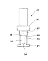
次に図5乃至図8を参照して、通常の長傘に使用する下ろくろの実施形態について説明する。この実施形態の下ろくろは、通常の長傘以外に、シャフト部分が伸縮する下はじきを備えた折り畳み式洋傘にも適用することができる。
図7において、符号32は、長傘のシャフト部分であり、これに上はじき(図示省略)と下はじき34が設けられている。
Next, with reference to FIG. 5 thru | or FIG. 8, embodiment of the ironing board used for a normal long umbrella is demonstrated. The armor of this embodiment can be applied not only to a normal long umbrella but also to a foldable western umbrella having a lower repellency in which a shaft portion expands and contracts.
In FIG. 7, reference numeral 32 denotes a shaft portion of a long umbrella, which is provided with an upper repelling (not shown) and a lower repelling 34.

このシャフト部分32に下ろくろ8がスライド自在に嵌挿配置されている。前記上はじきと下はじき34は、下ろくろ8のスリット30の、シャフト部分32に沿った、移動線上に配置されている。下ろくろ8の下はじき用操作片26には、U字状に切り込み線36が形成され、この切り込み線36によって前記上はじき用操作片26に、弾力性と可撓性を備えたU字状の下はじき用操作片38が形成されている。下ろくろ8の他の構成は、図1乃至図3に示す第1の実施形態の下ろくろ8の構成と同一であり、互いの同一の部分には同一の符号を付して対応関係を明らかにしている。 The shaft 8 is slidably fitted into the shaft portion 32. The upper and lower folds 34 are arranged on the movement line along the shaft portion 32 of the slit 30 of the bottom wheel 8. The lower repelling operation piece 26 has a U-shaped cut line 36 formed on the lower repelling operation piece 26, and the upper repelling operation piece 26 is provided with a U-shape having elasticity and flexibility by the cut line 36. A lower flipping operation piece 38 is formed. The other structure of the bottom wheel 8 is the same as the structure of the bottom wheel 8 of the first embodiment shown in FIGS. 1 to 3, and the same reference numerals are given to the same parts and the correspondence is clarified. I have to.

上記した構成において、下ろくろ8をシャフト部分32に、上はじきによって係止する作用は、第1の実施形態と同一であるのでその説明を省略する。
長傘を閉じるとき、シャフト部分32に沿って、下ろくろ8を傘柄側に、鍔部24の内周面が、下はじき34を越えるまでスライドさせる。下ろくろ8のこのスライドにより、下はじき34が下ろくろ8のスリット30内に位置すると、下はじき34の外側突出部34aはばね力によって、シャフト部分32から突出し、下はじき用操作片38に当接して、これを若干外方に押し上げる。
In the above-described configuration, the action of locking the bottom wheel 8 to the shaft portion 32 by upper repelling is the same as that of the first embodiment, and therefore the description thereof is omitted.
When closing the long umbrella, slide the lower skull 8 toward the umbrella handle along the shaft portion 32 until the inner peripheral surface of the collar portion 24 exceeds the lower repelling 34. When the lower repelling 34 is positioned in the slit 30 of the lower crossing 8 by this slide of the lower crossing wheel 8, the outer protruding portion 34a of the lower repelling 34 protrudes from the shaft portion 32 by the spring force and contacts the lower repelling operating piece 38. Touch it and push it slightly outward.

このとき下ろくろ8の鍔部24の、下ろくろ8の軸方向に対して垂直な係止面40と、下はじき34のストッパー部は対面し、このストッパー部と係止面40とによって、下ろくろ8の、シャフト部分32に沿った石突方向の移動が係止される。この下ろくろ8が、下はじき34によって係止された状態において、傘は閉じた状態となる。 At this time, the locking surface 40 of the collar portion 24 of the bottom wheel 8 is perpendicular to the axial direction of the bottom wheel 8 and the stopper portion of the lower repelling 34 faces each other. The movement of the potter's wheel 8 along the shaft portion 32 is stopped. In a state in which the lower skull 8 is locked by the lower flip 34, the umbrella is closed.

この係止状態を解除したいときは、下はじき用操作片38を図8に示すように、指で押し、操作片38を本体18の内側方向に屈曲させて、下はじき34をシャフト部分32の内側方向に引っ込める。これにより、下はじき34の、下ろくろ8に対する係止が外れ、下ろくろ8は自由にシャフト部分32に沿って、石突方向にスライド自在となる。
When it is desired to release this locked state, as shown in FIG. 8, the lower repelling operation piece 38 is pushed with a finger, the operation piece 38 is bent toward the inside of the main body 18, and the lower repelling 34 is moved to the shaft portion 32. Retract inward. As a result, the lower repelling 34 is disengaged from the lower runner 8, and the lower runner 8 is freely slidable along the shaft portion 32 in the stone bump direction.

本発明に係る下ろくろの外観図である。It is an external view of the roller according to the present invention. 同上、縦断面図である。It is a longitudinal cross-sectional view same as the above. 同上、縦断面図である。It is a longitudinal cross-sectional view same as the above. 傘のシャフト部分と骨部分を示す説明図である。It is explanatory drawing which shows the shaft part and bone part of an umbrella. 本発明の他の実施形態を示す下ろくろの外観図である。It is an external view of the bottom roller which shows other embodiment of this invention. 同上、正面図である。It is a front view same as the above. 同上、縦断面図である。It is a longitudinal cross-sectional view same as the above. 同上、縦断面図である。It is a longitudinal cross-sectional view same as the above.

符号の説明Explanation of symbols

2 シャフト部分
4 スライドシャフト
6 上部スライドシャフト
8 下ろくろ
8a 係止面
10 上ろくろ
12 骨部分
12a 受骨
14 上はじき
14a 外側突出部
14b ストッパー部
15 ストッパー
16 連結部
18 本体
20 中空部
22 凹溝部
24 鍔部
26 操作片
27 カバー片
28 管璧
30 スリット
32 シャフト部分
34 下はじき
34a 外側突出部
36 切り込み線
38 操作片
40 係止面
2 Shaft portion 4 Slide shaft 6 Upper slide shaft 8 Lower skull 8a Locking surface 10 Upper skull 12 Bone portion 12a Receiving bone 14 Upper repelling 14a Outer protruding portion 14b Stopper portion 15 Stopper 16 Connecting portion 18 Body 20 Hollow portion 22 Recessed groove portion 24 Gutter part 26 Operation piece 27 Cover piece 28 Pipe wall 30 Slit 32 Shaft part 34 Lower repelling 34a Outer protrusion 36 Cut line 38 Operation piece 40 Locking surface

Claims (4)

筒状の本体18に形成された連結部16が傘の骨部分12に連結し、該筒状の本体18を傘のシャフト部分に沿ってスライドさせて、傘の開閉を行うための下ろくろであって、前記シャフト部分に設けられた上はじき14を前記本体18の管璧28から突出する方向に開放するための前記本体18の管璧28に形成されたスリット30と、前記スリット30から突出する上はじき14の外側突出部14aの石突側の端面を係止するための前記本体の管璧28に形成された係止面8aと、前記スリット30の傘柄側の端部に隣接して前記本体18の管璧28に設けられた鍔部24と、前記スリット30に所定の間隔を存して略平行に対面するように前記鍔部24に揺動自在に形成された細長状の上はじき用操作片26とを備え、前記操作片26を前記本体18の内側方向に屈曲させて前記スリット30から突出する上はじき14の上側突出部14aを前記係止面8aから外れる方向に押し込むことができるようにしたことを特徴とする傘の下ろくろ。 A connecting portion 16 formed on the tubular body 18 is connected to the bone portion 12 of the umbrella, and the tubular body 18 is slid along the shaft portion of the umbrella to open and close the umbrella. A slit 30 formed in the tube wall 28 of the main body 18 for releasing the upper repelling 14 provided in the shaft portion in a direction protruding from the tube wall 28 of the main body 18, and protruding from the slit 30. Next, the locking surface 8a formed on the tube wall 28 of the main body for locking the end surface of the outer protrusion 14a of the outer repellency 14 is adjacent to the umbrella handle end of the slit 30. An elongate upper portion formed swingably on the flange 24 so as to face the flange 24 provided on the pipe wall 28 of the main body 18 and the slit 30 at a predetermined interval and substantially parallel to each other. A repelling operation piece 26, and the operation piece 26. Umbrella pegs characterized in that the upper protrusion 14a of the upper repellant 14 that is bent inwardly of the main body 18 and protrudes from the slit 30 can be pushed in a direction away from the locking surface 8a. . 前記上はじき用操作片26を可撓弾力性を有する部材により構成したことを特徴とする請求項1に記載の傘の下ろくろ。 The umbrella repellent according to claim 1, wherein the upper repelling operation piece (26) is composed of a member having flexible elasticity. 前記スリット30の他に、前記本体18の管璧28に、下はじき用のスリットを設け、該スリットの傘柄側の端部に位置して、前記本体18の管璧28に前記シャフト部分に設けた下はじきと係合するための係止面を設けたことを特徴とする請求項1に記載の傘の下ろくろ。 In addition to the slit 30, a lower repelling slit is provided in the tube wall 28 of the main body 18, located at the end of the slit on the umbrella handle side, and on the tube wall 28 of the main body 18 on the shaft portion. The umbrella peg according to claim 1, further comprising a locking surface for engaging with the provided lower repellent. 筒状の本体18に形成された連結部16が傘の骨部分12に連結し、該筒状の本体18を傘のシャフト部分に沿ってスライドさせて、傘の開閉を行うための下ろくろであって、前記シャフト部分に設けられた上はじき14を前記本体18の管璧28から突出する方向に開放するための前記本体18の管璧28に形成されたスリット30と、前記スリット30から突出する上はじき14の外側突出部14aの石突側の端面を係止するための前記本体の管璧28に形成された係止面8aと、前記スリット30の傘柄側の端部に隣接して前記本体18の管璧28に設けられた鍔部24と、前記スリット30に所定の間隔を存して略平行に対面するように前記鍔部24に揺動自在に形成された細長状の上はじき用操作片26とを備え、前記操作片26を前記本体18の内側方向に屈曲させて前記スリット30から突出する上はじき14の上側突出部14aを前記係止面8aから外れる方向に押し込むことができるようにし、前記スリット30の傘柄側の端部に位置して、前記本体18の管璧28に前記シャフト部分に設けた下はじきと係合するための係止面40を設け、前記上はじき用操作片26にU字状にスリットを設けてU字状の下はじき用操作片38を揺動自在に形成し、該下はじき用操作片38を前記本体18の内側方向に屈曲させて前記スリット30から突出する下はじき34の外側突出部34aを前記下はじき用係止面40から外れる方向に押し込むことができるようにしたことを特徴とする傘の下ろくろ。 A connecting portion 16 formed on the tubular body 18 is connected to the bone portion 12 of the umbrella, and the tubular body 18 is slid along the shaft portion of the umbrella to open and close the umbrella. A slit 30 formed in the tube wall 28 of the main body 18 for releasing the upper repelling 14 provided in the shaft portion in a direction protruding from the tube wall 28 of the main body 18, and protruding from the slit 30. Next, the locking surface 8a formed on the tube wall 28 of the main body for locking the end surface of the outer protrusion 14a of the outer repellency 14 is adjacent to the umbrella handle end of the slit 30. An elongate upper portion formed swingably on the flange 24 so as to face the flange 24 provided on the pipe wall 28 of the main body 18 and the slit 30 at a predetermined interval and substantially parallel to each other. A repelling operation piece 26, and the operation piece 26. The upper protrusion 14a of the upper repellant 14 that is bent inwardly of the main body 18 and protrudes from the slit 30 can be pushed in a direction away from the locking surface 8a. Is located on the tube wall 28 of the main body 18 and is provided with a locking surface 40 for engaging with the lower repelling provided on the shaft portion, and the upper repelling operating piece 26 is provided with a U-shaped slit. The U-shaped lower repelling operation piece 38 is formed so as to be swingable, and the lower repelling operation piece 38 is bent inward of the main body 18 so as to protrude from the slit 30. An umbrella glove characterized in that 34a can be pushed in a direction away from the lower repelling locking surface 40.
JP2008220644A 2008-08-29 2008-08-29 Under the umbrella Expired - Fee Related JP5270262B2 (en)

Priority Applications (1)

Application Number Priority Date Filing Date Title
JP2008220644A JP5270262B2 (en) 2008-08-29 2008-08-29 Under the umbrella

Applications Claiming Priority (1)

Application Number Priority Date Filing Date Title
JP2008220644A JP5270262B2 (en) 2008-08-29 2008-08-29 Under the umbrella

Publications (3)

Publication Number Publication Date
JP2010051607A true JP2010051607A (en) 2010-03-11
JP2010051607A5 JP2010051607A5 (en) 2011-09-15
JP5270262B2 JP5270262B2 (en) 2013-08-21

Family

ID=42068151

Family Applications (1)

Application Number Title Priority Date Filing Date
JP2008220644A Expired - Fee Related JP5270262B2 (en) 2008-08-29 2008-08-29 Under the umbrella

Country Status (1)

Country Link
JP (1) JP5270262B2 (en)

Cited By (3)

* Cited by examiner, † Cited by third party
Publication number Priority date Publication date Assignee Title
US20120174953A1 (en) * 2011-01-06 2012-07-12 Hsia-Hui Chen Runner fastening device for an umbrella
JP2013085949A (en) * 2011-10-20 2013-05-13 Jui-Chieh Chen Umbrella
JP2014133129A (en) * 2013-01-10 2014-07-24 Chuanyang Chen Opening/closing device of folding umbrella

Citations (4)

* Cited by examiner, † Cited by third party
Publication number Priority date Publication date Assignee Title
JPS5413764U (en) * 1977-06-30 1979-01-29
JPH04110515U (en) * 1991-03-06 1992-09-25 福太洋傘工廠股ふん有限公司 potter's wheel under a western umbrella
JPH09154610A (en) * 1995-12-01 1997-06-17 Mikawa Shiyousuke Ring of umbrella
JP2000050928A (en) * 1998-08-14 2000-02-22 Zoei Go Lower runner for manually operating umbrella

Patent Citations (4)

* Cited by examiner, † Cited by third party
Publication number Priority date Publication date Assignee Title
JPS5413764U (en) * 1977-06-30 1979-01-29
JPH04110515U (en) * 1991-03-06 1992-09-25 福太洋傘工廠股ふん有限公司 potter's wheel under a western umbrella
JPH09154610A (en) * 1995-12-01 1997-06-17 Mikawa Shiyousuke Ring of umbrella
JP2000050928A (en) * 1998-08-14 2000-02-22 Zoei Go Lower runner for manually operating umbrella

Cited By (5)

* Cited by examiner, † Cited by third party
Publication number Priority date Publication date Assignee Title
US20120174953A1 (en) * 2011-01-06 2012-07-12 Hsia-Hui Chen Runner fastening device for an umbrella
JP2012143532A (en) * 2011-01-06 2012-08-02 Hsia-Hui Chen Runner fastening device for umbrella
US8459281B2 (en) * 2011-01-06 2013-06-11 Hsia-Hui Chen Runner fastening device for an umbrella
JP2013085949A (en) * 2011-10-20 2013-05-13 Jui-Chieh Chen Umbrella
JP2014133129A (en) * 2013-01-10 2014-07-24 Chuanyang Chen Opening/closing device of folding umbrella

Also Published As

Publication number Publication date
JP5270262B2 (en) 2013-08-21

Similar Documents

Publication Publication Date Title
JP5398782B2 (en) Runner fixing device for umbrella
US3467116A (en) Pick-up walking stick
JP5270262B2 (en) Under the umbrella
JP2008142310A (en) Runner engagement mechanism
JP6966576B2 (en) Needle automatic retractable blood collection needle
BR0116050A (en) Medical needle safety guard
JP6169794B2 (en) Safety blood collection needle
JP5481533B2 (en) umbrella
KR101707129B1 (en) Length adjustable walking assistance device
WO2009125612A1 (en) Telescopic shaft mechanism for use in folding umbrella
CN109963479B (en) Umbrella
US2515493A (en) Folding umbrella
KR101053902B1 (en) Safety umbrella
JP2008188325A (en) Self-sustaining stick body
JP2010051607A5 (en)
JP2019030632A (en) Quick and laborsaving device for opening/closing umbrella
JP5575296B1 (en) Telescopic shaft for foldable umbrella
KR101517536B1 (en) Door knob
CN208463127U (en) Multi-fold umbrella opens the fastening structure that closes one&#39;s umbrella
JP3170930U (en) umbrella
JP5759050B1 (en) umbrella
JP3156397U (en) Umbrella with a retractable center rod
JP2008188185A (en) Contractible one-touch folding fan
JP5916699B2 (en) Folding umbrella opening and closing device
US3003511A (en) Collapsible umbrellas

Legal Events

Date Code Title Description
A521 Written amendment

Free format text: JAPANESE INTERMEDIATE CODE: A523

Effective date: 20110802

A621 Written request for application examination

Free format text: JAPANESE INTERMEDIATE CODE: A621

Effective date: 20110805

A977 Report on retrieval

Free format text: JAPANESE INTERMEDIATE CODE: A971007

Effective date: 20130329

A131 Notification of reasons for refusal

Free format text: JAPANESE INTERMEDIATE CODE: A131

Effective date: 20130404

A521 Written amendment

Free format text: JAPANESE INTERMEDIATE CODE: A523

Effective date: 20130412

TRDD Decision of grant or rejection written
A01 Written decision to grant a patent or to grant a registration (utility model)

Free format text: JAPANESE INTERMEDIATE CODE: A01

Effective date: 20130502

A61 First payment of annual fees (during grant procedure)

Free format text: JAPANESE INTERMEDIATE CODE: A61

Effective date: 20130509

R150 Certificate of patent or registration of utility model

Free format text: JAPANESE INTERMEDIATE CODE: R150

LAPS Cancellation because of no payment of annual fees