JP2010050300A - Excimer laser device - Google Patents
Excimer laser device Download PDFInfo
- Publication number
- JP2010050300A JP2010050300A JP2008213530A JP2008213530A JP2010050300A JP 2010050300 A JP2010050300 A JP 2010050300A JP 2008213530 A JP2008213530 A JP 2008213530A JP 2008213530 A JP2008213530 A JP 2008213530A JP 2010050300 A JP2010050300 A JP 2010050300A
- Authority
- JP
- Japan
- Prior art keywords
- laser
- chamber
- gas
- air spring
- laser chamber
- Prior art date
- Legal status (The legal status is an assumption and is not a legal conclusion. Google has not performed a legal analysis and makes no representation as to the accuracy of the status listed.)
- Granted
Links
- 230000003287 optical effect Effects 0.000 claims abstract description 25
- 230000008602 contraction Effects 0.000 claims abstract description 5
- 238000010926 purge Methods 0.000 claims description 15
- 238000007599 discharging Methods 0.000 abstract description 2
- 239000007789 gas Substances 0.000 description 34
- 238000000034 method Methods 0.000 description 12
- 238000002347 injection Methods 0.000 description 10
- 239000007924 injection Substances 0.000 description 10
- 230000010355 oscillation Effects 0.000 description 9
- 238000010586 diagram Methods 0.000 description 7
- 238000006073 displacement reaction Methods 0.000 description 6
- 101100456571 Mus musculus Med12 gene Proteins 0.000 description 5
- 238000013016 damping Methods 0.000 description 5
- 230000000694 effects Effects 0.000 description 5
- PXGOKWXKJXAPGV-UHFFFAOYSA-N Fluorine Chemical compound FF PXGOKWXKJXAPGV-UHFFFAOYSA-N 0.000 description 4
- 229910052731 fluorine Inorganic materials 0.000 description 4
- 239000011737 fluorine Substances 0.000 description 4
- 238000002955 isolation Methods 0.000 description 4
- 230000003321 amplification Effects 0.000 description 3
- 230000005284 excitation Effects 0.000 description 3
- 238000003199 nucleic acid amplification method Methods 0.000 description 3
- IJGRMHOSHXDMSA-UHFFFAOYSA-N Atomic nitrogen Chemical compound N#N IJGRMHOSHXDMSA-UHFFFAOYSA-N 0.000 description 2
- 230000002411 adverse Effects 0.000 description 2
- 238000001514 detection method Methods 0.000 description 2
- 230000005484 gravity Effects 0.000 description 2
- 238000007789 sealing Methods 0.000 description 2
- 239000004065 semiconductor Substances 0.000 description 2
- 239000006096 absorbing agent Substances 0.000 description 1
- 238000010521 absorption reaction Methods 0.000 description 1
- 230000001133 acceleration Effects 0.000 description 1
- 230000004075 alteration Effects 0.000 description 1
- 238000006243 chemical reaction Methods 0.000 description 1
- 230000006378 damage Effects 0.000 description 1
- 239000006185 dispersion Substances 0.000 description 1
- 239000002184 metal Substances 0.000 description 1
- 229910052757 nitrogen Inorganic materials 0.000 description 1
- 230000000644 propagated effect Effects 0.000 description 1
- 230000001902 propagating effect Effects 0.000 description 1
- 230000003595 spectral effect Effects 0.000 description 1
- 230000006641 stabilisation Effects 0.000 description 1
- 238000011105 stabilization Methods 0.000 description 1
Images


Landscapes
- Exposure And Positioning Against Photoresist Photosensitive Materials (AREA)
- Lasers (AREA)
- Exposure Of Semiconductors, Excluding Electron Or Ion Beam Exposure (AREA)
Abstract
Description
本発明は、エキシマレーザ装置に関し、特に、半導体露光装置用光源として用いられるエキシマレーザシステムで使用される振動吸収装置に関するものである。 The present invention relates to an excimer laser device, and more particularly to a vibration absorber used in an excimer laser system used as a light source for a semiconductor exposure apparatus.
図5は、従来の一般的なエキシマレーザシステム1及び共振器20を示す図である。 FIG. 5 is a diagram showing a conventional general excimer laser system 1 and a resonator 20.
レーザチャンバ11はレーザチャンバ11内部にレーザガスを封入して使用するものである。ArFエキシマレーザの場合はAr、フッ素、NeあるいはHe、Xeを使用し、KrFエキシマレーザの場合はKr、フッ素、NeあるいはHeを使用する。
The
レーザチャンバ11は対向する2本の電極12を有しており、一方に電圧を印加し二つの電極12間に放電を発生させる。放電によって発生した光はウィンドウとしての光学窓13を通り抜けて共振器20間を往復しレーザ光となり部分反射ミラー21を透過して、出力エネルギーとして取り出される。
The
共振器20の一端では、部分反射ミラー21がホルダに収納されキャビティ22に取り付けられている。さらに、共振器20の他端では、ビームを拡大するプリズム24と波長を選択する回折格子25を収めた箱26がキャビティ22に取り付けられている。これらキャビティ22は第一の定盤31に取り付けられている。
At one end of the resonator 20, a
また、レーザチャンバ11にローラーを使用している場合にはローラーによりレーザチャンバ11が動かないようにレーザチャンバ11をレールや第二の定盤32に固定して動作させる。
When a roller is used for the
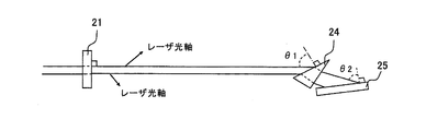
部分反射ミラー21、プリズム24及び回折格子25は所定の角度でビームが入射するようにあらかじめ調整されている。図6に部分反射ミラー21に直角に入射し、プリズム24にθ1、回折格子25にθ2で入射するよう調整した様子を示す。
The partial reflection mirror 21, the
レーザチャンバ11はさらにレーザガスを循環させるためのクロスフローファン14を有し、レーザチャンバ11に取り付けられたモータ15と連結している。モータ15によってクロスフローファン14は回転し、レーザガスをレーザチャンバ11内部で循環させる。
The
レーザガス循環の目的はレーザチャンバ11内に設置されたラジエタ(図示せず)と熱交換を行うことと、電極12間に常にフレッシュなレーザガスを供給することである。
The purpose of the laser gas circulation is to perform heat exchange with a radiator (not shown) installed in the
このクロスフローファン14が回転することにより、振動が発生する。この振動はクロスフローファンのアンバランス量に起因している。
The
レーザチャンバ11は第二の定盤32に固定されており、第二の定盤32は振動吸収手段40を介して第一の定盤31に固定されている。
The
レーザチャンバ11で発生した振動は第二の定盤32、振動吸収手段40、第一の定盤31へと伝播する。ただし、振動吸収手段40がある場合には伝播する振動は小さくなる。
The vibration generated in the
伝播した振動は第一の定盤31に取り付けられたキャビティ22を通して部分反射ミラー21やプリズム24、回折格子25を変位させる。その結果、各々の入射角度がずれ波長変動を引き起こす場合がある。
The propagated vibration displaces the
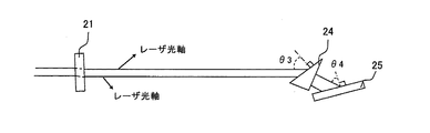
図6は、通常の場合の部分反射ミラー21、プリズム24及び回折格子25の関係を示す図、図7は、部分反射ミラー21、プリズム24及び回折格子25が変位した例を示す図である。
FIG. 6 is a diagram illustrating a relationship between the
通常時、部分反射ミラー21、プリズム24及び回折格子25の関係は、図6に示したように所定の入射角で光が入るように調整されている。しかしながら、図7に示すように、振動等により部分反射ミラー21、プリズム24及び回折格子25がそれぞれ変位すると、それぞれの入射角が変化し波長が変化したり、スペクトル線幅が変化したり、出力エネルギーが変化したりしていた。
Normally, the relationship between the
次に、近年主流になりつつあるMOPAやInjection Lock方式における振動の影響を説明する。図8は、図5に示したチャンバを2つ並べたシステムを示す図である。下のチャンバ11(以後オシレータチャンバと呼ぶ)及び共振器20でレーザ光の線幅を狭めて、図中の注入光軸のように数枚の折り返しミラー50を経由して上のチャンバ61(以後アンプチャンバと呼ぶ)に注入される。
Next, the influence of vibration in the MOPA and Injection Lock systems that are becoming mainstream in recent years will be described. FIG. 8 is a diagram showing a system in which two chambers shown in FIG. 5 are arranged. The line width of the laser light is narrowed by the lower chamber 11 (hereinafter referred to as the oscillator chamber) and the resonator 20, and the upper chamber 61 (hereinafter referred to as the injection optical axis in the figure) is passed through
アンプチャンバ61は注入されたレーザ光を基にレーザ光が立ち上がり、アンプリアミラー62とアンプフロントミラー63の間を共振し、アンプフロントミラー63から出射する。
In the
このようなシステムにおいて個々のチャンバ11,61の共振器20を構成するミラー21、プリズム24及び回折格子25がレーザチャンバ11,61の振動の影響を受けることは言うまでもない。これらに加えて、折り返しミラー50に与えられる悪影響もある。注入光軸は、このようなシステムにとっては非常に重要であり、注入光軸の位置、角度がずれるとほとんど全ての光品位が劣化する。
In such a system, it goes without saying that the
従って、振動を折り返しミラー50に伝えないことは、このようなシステムでは非常に重要なことである。
Therefore, it is very important not to transmit vibration to the folding
近年、半導体露光装置用光源としては、このようなKrF、ArFエキシマレーザシス
テムが主流になっている。そして、露光装置用光源に求められる性能は以下(1)〜(3)に示すようなものである。
In recent years, such KrF and ArF excimer laser systems have become mainstream as light sources for semiconductor exposure apparatuses. The performance required for the light source for the exposure apparatus is as shown in the following (1) to (3).
(1)高ドーズ安定性の確保とスループット向上のために20W以上の出力が要求されている(KrFでは概ね40W以上、ArFでは概ね60W以上)。 (1) In order to ensure high dose stability and improve throughput, an output of 20 W or more is required (approximately 40 W or more for KrF and approximately 60 W or more for ArF).
(2)投影レンズの高解像度化のために投影レンズの高NA化が進められている。これに伴い色収差が問題となり、狭帯域化が要求されている。 (2) The NA of the projection lens is being increased to increase the resolution of the projection lens. Along with this, chromatic aberration becomes a problem, and a narrow band is required.
(3)安定した露光を実現するために、波長、出力エネルギーの高安定化が要求されている。 (3) In order to realize stable exposure, high stabilization of wavelength and output energy is required.
高出力化と狭帯域化を実現するために、近年ではMOPA方式(MasterOscillator Power Amplifier)やInjection Lock方式(注入同期)を採用した露光装置用光源が主流になりつ
つある。
In recent years, light sources for exposure apparatuses adopting the MOPA method (Master Oscillator Power Amplifier) and Injection Lock method (injection locking) are becoming mainstream in order to achieve higher output and narrower bandwidth.
MOPA方式やInjection Lock方式ではレーザチャンバを2つ以上使用し、一つは発振段として使用し、発振段で出てきたレーザ光を増幅段に所定のタイミングで注入する。発振段で狭帯域化を実現し、増幅段で高出力化を実現している。 In the MOPA method or the injection lock method, two or more laser chambers are used, one is used as an oscillation stage, and laser light emitted from the oscillation stage is injected into the amplification stage at a predetermined timing. A narrow band is realized in the oscillation stage, and a high output is realized in the amplification stage.
レーザチャンバを一つだけ使用する従来のレーザシステムと比較するとMOPA方式やInjection Lock方式ではレーザ光軸のアライメントが非常に重要である。発振段から増幅段
へどのようにレーザ光を注入するかは特に重要であり、注入の仕方によってほとんど全ての光性能が変化すると言える。このため、光軸のズレは注入の仕方を変化させ、光性能を劣化させる。
Compared with conventional laser systems that use only one laser chamber, alignment of the laser optical axis is very important in the MOPA method and the injection lock method. How laser light is injected from the oscillation stage to the amplification stage is particularly important, and it can be said that almost all optical performance changes depending on the injection method. For this reason, the deviation of the optical axis changes the injection method and degrades the optical performance.
発振波長、出力エネルギーの安定化のためには振動を低減することが有効である。エキシマレーザシステム内部に発生した振動は予め調整された部分反射ミラー、プリズム、回折格子、スリットを振動させる。この振動によりレーザ光軸にずれが生じて発振波長の変動あるいは出力エネルギーの変動を引き起こす。 To stabilize the oscillation wavelength and output energy, it is effective to reduce vibration. The vibration generated in the excimer laser system vibrates a partially reflecting mirror, prism, diffraction grating, and slit that are adjusted in advance. This vibration causes a shift in the laser optical axis, causing fluctuations in oscillation wavelength or output energy.
発振波長の変動は、レーザ光軸のずれにより回折格子に入射する角度が変動することで起こる。出力エネルギーの変動は、発振波長の変動の理由に加えて通過するゲイン領域がわずかにずれることから生じると推測している。 The fluctuation of the oscillation wavelength occurs when the angle of incidence on the diffraction grating varies due to the deviation of the laser optical axis. It is assumed that the fluctuation of the output energy is caused by the fact that the passing gain region is slightly shifted in addition to the reason of the fluctuation of the oscillation wavelength.
このようにエキシマレーザシステム内の振動は、波長や出力エネルギーの安定性に大きな影響を及ぼすため、主に2つの対策をとることで波長や出力エネルギーの安定性を向上させてきた。 As described above, the vibration in the excimer laser system greatly affects the stability of the wavelength and the output energy. Therefore, the stability of the wavelength and the output energy has been improved mainly by taking two measures.
一つは振動自身を小さくする方法である。エキシマレーザシステム内で発生し、波長や出力エネルギーの安定性に悪影響を及ぼす振動はレーザチャンバで発生したものである。 One is to reduce the vibration itself. Vibrations that occur in the excimer laser system and adversely affect the stability of wavelength and output energy are generated in the laser chamber.
エキシマレーザはレーザガスを封入するレーザチャンバを有する。レーザチャンバ内には対向した2本の電極、レーザガスを循環させるためのクロスフローファン、循環したガスの熱交換を行うためのラジエタ等が設置されている。クロスフローファンはチャンバに取り付けられたモータによって回転する。 Excimer lasers have a laser chamber that encloses a laser gas. In the laser chamber, two electrodes facing each other, a cross flow fan for circulating the laser gas, a radiator for exchanging heat of the circulating gas, and the like are installed. The cross flow fan is rotated by a motor attached to the chamber.
クロスフローファンは回転体であり、クロスフローファンの中心軸上に重心が存在するのが理想であり、そのように調整される。しかし、重心位置を完全にクロスフローファン中心軸上に調整するのは不可能であり、わずかなアンバランス量が生じる。このアンバランス量によりレーザチャンバが振動し、レーザ筐体内に伝播する。 The cross flow fan is a rotating body, and it is ideal that the center of gravity exists on the central axis of the cross flow fan, and the cross flow fan is adjusted as such. However, it is impossible to adjust the position of the center of gravity completely on the center axis of the cross flow fan, and a slight unbalance amount is generated. The laser chamber vibrates due to the unbalanced amount and propagates into the laser casing.
よって、アンバランス量を極力小さくすることで振動を小さくすることが対策になり得る。しかし実際にはアンバランス量を完全になくすことは極めて困難である。さらに近年は露光用光源には高繰り返し化が求められるにつれ、クロスフローファンの回転数は上昇している。すなわち、アンバランス量を減らしたとしても、その効果を上回る回転数でクロスフローファンが回転するため、全体としての効果は小さい。 Therefore, reducing the vibration by reducing the unbalance amount as much as possible can be a countermeasure. However, in practice, it is extremely difficult to completely eliminate the unbalance amount. Further, in recent years, as the exposure light source is required to have a high repetition rate, the rotational speed of the cross flow fan has increased. That is, even if the unbalance amount is reduced, the cross flow fan rotates at a rotational speed that exceeds the effect, so that the overall effect is small.
二つ目の対策は防振・除振をすることである。この対策に関しては、以下のような技術が開示されている。 The second measure is to provide vibration isolation and vibration isolation. Regarding this countermeasure, the following techniques are disclosed.
まず、起振源であるチャンバと光性能を決める光学素子を保持するホルダの間に振動減衰部材を配置することで、ホルダに伝わる振動を小さくすることを狙って、レーザチャンバと光学素子ホルダの間に振動減衰部材を配置した技術がある(特許文献1)。 First, by arranging a vibration damping member between the chamber that is the excitation source and the holder that holds the optical element that determines the optical performance, the vibration of the laser chamber and the optical element holder is reduced. There is a technique in which a vibration damping member is disposed between them (Patent Document 1).
また、振動吸収手段として特に空気バネを上げ、さらに位置検出手段も加え、レーザ発
振のための光学系を固定した第1の定盤と、レーザチャンバを固定した第2の定盤の間に振動吸収手段を配置した技術がある(特許文献2)。
In addition, an air spring is raised as a vibration absorbing means, and a position detecting means is further added to vibrate between the first surface plate to which the optical system for laser oscillation is fixed and the second surface plate to which the laser chamber is fixed. There is a technique in which an absorbing means is arranged (Patent Document 2).
しかしながら、特許文献1に記載されたものは、振動減衰部材の耐久性に問題がある。振動減衰部材は、使用している間に経時変化が起きる。防振ゴムの場合の経時変化は、ヘタリとしてよく知られている。沈み込みが発生したり、硬化が起こるため、所定のレーザ性能が得られなくなる。 However, the device described in Patent Document 1 has a problem in durability of the vibration damping member. The vibration damping member changes with time during use. The change over time in the case of the vibration-proof rubber is well known as sag. Since the sinking occurs and the curing occurs, the predetermined laser performance cannot be obtained.
また、特許文献2に記載されたものは、振動減衰部材を空気バネにしたことが大きな特長である。空気バネは空気圧を加えることで常に反力を加えられているため、経時変化が起こることはない。
In addition, what is described in
しかしながら、特許文献2に記載されたものには以下のような課題がある。
However, what is described in
まず第1に、空気バネが様々な方向に変形できるので、アライメントがずれやすい。例えば、空気バネで加振源であるレーザチャンバからキャビティに伝わる振動を絶縁した場合を考える。キャビティには、波長を選択する回折格子、ビームを拡大するプリズム、部分反射ミラーが取り付けられている。そして、空気バネはあらゆる方向に動くことが可能で、荷重が加わる鉛直方向、水平方向に変位・変形することができる。 First, since the air spring can be deformed in various directions, the alignment tends to shift. For example, consider a case where the vibration transmitted from the laser chamber, which is the excitation source, to the cavity is insulated by an air spring. A diffraction grating for selecting a wavelength, a prism for expanding a beam, and a partial reflection mirror are attached to the cavity. The air spring can move in any direction, and can be displaced / deformed in the vertical and horizontal directions where a load is applied.
近年、露光に使用される光の波長が短くなるに従い、レーザ内の光路を窒素でパージする必要がある。従って、図9に示すように、レーザチャンバ11とキャビティ22を例えばダクト70のようなもので連結しなければならない。
In recent years, as the wavelength of light used for exposure becomes shorter, it is necessary to purge the optical path in the laser with nitrogen. Therefore, as shown in FIG. 9, the
このように構成されたシステムにおいて、空気バネが自由に動くことができるならば、レーザチャンバ11とキャビティ22を連結するダクト70を通じて、レーザチャンバ11からキャビティ22に力が加わってしまう。キャビティ22はその力でたわみ、アライメントは、ずれてしまう。
In the system configured as described above, if the air spring can freely move, a force is applied from the
近年では光源の高出力の要求に伴いMOPAシステムやI/Lシステムを採用することも多い
が、いずれもアライメントずれに対しては非常に敏感であり、この点を克服する必要がある。
In recent years, MOPA systems and I / L systems are often used in response to demands for high output of light sources, but both are very sensitive to misalignment and must be overcome.
第2に、空気バネに空気圧をかけるとバネとして作用する。反対に空気圧が抜けてしまうと、バネとしては作用せず、チャンバは沈み込んでしまう場合があった。 Second, when air pressure is applied to the air spring, it acts as a spring. On the other hand, if the air pressure is released, the chamber does not act as a spring and the chamber may sink.
例えば、レーザシステムに空気バネを採用した場合、停電等が起こると空気圧が抜け、チャンバが沈み込んでしまう。この時、ダクトを通じてキャビティに力が加わってしまい、アライメントがずれてしまう。 For example, when an air spring is employed in the laser system, the air pressure is lost and the chamber sinks when a power failure occurs. At this time, force is applied to the cavity through the duct, resulting in misalignment.
第3に、空気バネを動作させるために圧縮機が必要であった。空気バネは空気圧をかけて初めて所定の除振効果を発揮する。そして、空気圧を上げるためには圧縮機が必要であった。したがって、圧縮機を設置するためのコストが必要になると共に、圧縮機の振動も考慮する必要があった。 Third, a compressor was required to operate the air spring. The air spring exerts a predetermined vibration isolation effect only when air pressure is applied. In order to increase the air pressure, a compressor was required. Therefore, the cost for installing the compressor is required, and the vibration of the compressor needs to be considered.
本発明は従来技術のこのような問題点に鑑みてなされたものであり、その目的は、アライメントのずれを低減させると共に、簡単な構造で、低コストなエキシマレーザ装置を提供することである。 The present invention has been made in view of such problems of the prior art, and an object of the present invention is to provide an excimer laser device that reduces the misalignment and has a simple structure and a low cost.
そのために、本発明は、レーザチャンバと、前記レーザチャンバの一方の側とその反対側に設置された共振器と、前記レーザチャンバ内部に封入されたレーザガスと、前記レーザガスを励起する手段と、励起された前記レーザガスから発生する光が前記レーザチャンバ外部へ出射するために前記レーザチャンバに設けられた2つのウィンドウと、前記レーザガスを循環させるクロスフローファンと、前記レーザチャンバを支持する振動吸収手段と、を備えたエキシマレーザ装置において、前記振動吸収手段は、気体を流入排出させて膨張収縮する空気バネと、前記空気バネの水平方向への膨張収縮を規制する容器と、を有することを特徴とする。 For this purpose, the present invention comprises a laser chamber, a resonator installed on one side of the laser chamber and the opposite side thereof, a laser gas sealed inside the laser chamber, means for exciting the laser gas, and excitation Two windows provided in the laser chamber for emitting light generated from the laser gas emitted to the outside of the laser chamber, a cross flow fan for circulating the laser gas, and vibration absorbing means for supporting the laser chamber The vibration absorbing means includes an air spring that expands and contracts by injecting and discharging gas, and a container that controls expansion and contraction of the air spring in the horizontal direction. To do.
また、前記振動吸収手段は、一端を前記空気バネに取り付けられ、他端を前記チャンバ側に取り付けられた連結部材を有し、前記容器は、前記連結部材を挿通する開口を有することを特徴とする。 Further, the vibration absorbing means has a connecting member having one end attached to the air spring and the other end attached to the chamber side, and the container has an opening through which the connecting member is inserted. To do.
また、前記レーザガスあるいは光路をパージするためのパージガスを前記空気バネに流入排出させることを特徴とする。 Further, the purge gas for purging the laser gas or the optical path is caused to flow into and out of the air spring.
また、前記振動吸収手段は、前記空気バネの両端を連結固定する着脱可能な剛体を有することを特徴とする。 The vibration absorbing means may include a detachable rigid body that connects and fixes both ends of the air spring.
また、前記レーザチャンバを複数有することを特徴とする。 Further, a plurality of the laser chambers are provided.
本発明のエキシマレーザ装置は、アライメントのずれを低減させると共に、簡単な構造で、コストを低く抑えることができる。 The excimer laser device of the present invention can reduce misalignment and can keep the cost low with a simple structure.
以下、本発明に係る実施形態のエキシマレーザ装置について説明する。 Hereinafter, an excimer laser device according to an embodiment of the present invention will be described.
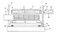
図1は、本発明に係るエキシマレーザシステム1及び共振器20を示す図である。 FIG. 1 is a diagram showing an excimer laser system 1 and a resonator 20 according to the present invention.
レーザチャンバ11はレーザチャンバ11内部にレーザガスを封入して使用するものである。ArFエキシマレーザの場合はAr、フッ素、NeあるいはHe、Xeを使用し、KrFエキシマレーザの場合はKr、フッ素、NeあるいはHeを使用する。
The
レーザチャンバ11は対向する2本の電極12を有しており、一方に電圧を印加し二つの電極12間に放電を発生させる。放電によって発生した光は光学窓13を通り抜けて共振器20間を往復しレーザ光となり部分反射ミラー21を透過して、出力エネルギーとして取り出される。
The
共振器20の一端では、部分反射ミラー21がホルダ22に収納されキャビティ22に取り付けられている。さらに、共振器20の他端では、ビームを拡大するプリズム24と波長を選択する回折格子25を収めた箱26がキャビティ22に取り付けられている。これらキャビティ22は第一の定盤31に取り付けられている。
At one end of the resonator 20, a
また、レーザチャンバ11には移動を容易にするためのローラー33が設けられている
。このローラー33によりレーザチャンバ11が動いてしまわないようにレーザチャンバ11をレール34に固定して動作させる。
The
部分反射ミラー21、プリズム24及び回折格子25は所定の角度でビームが入射するようにあらかじめ調整されている。
The
レーザチャンバ11はさらにレーザガスを循環させるためのクロスフローファン14を有し、レーザチャンバ11に取り付けられたモータ15と連結している。モータ15によってクロスフローファン14は回転し、レーザガスをレーザチャンバ11内部で循環させる。
The
レーザガス循環の目的はレーザチャンバ11内に設置されたラジエタ(図示せず)と熱交換を行うことと、電極12間に常にフレッシュなレーザガスを供給することである。
The purpose of the laser gas circulation is to perform heat exchange with a radiator (not shown) installed in the
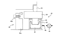
図2は、振動吸収手段40を示す図である。図2に示すように、本実施形態の振動吸収手段40は、空気バネ41を容器としてのシリンダ42の中に入れている。空気バネ41は、気体を流入排出させて膨張収縮し、シリンダ42に当接することにより水平方向への膨張を所定の位置までに規制されている。空気バネ41には、連結部材としてのシャフト43の一端が取り付けられている。シャフト43の他端は、レール34を介してレーザチャンバ11側に取り付けられている。シャフト43は、空気バネ41の膨張収縮により、シリンダ42の上方のシリンダ開口42a内を上下動可能に移動することが可能である。
FIG. 2 is a view showing the
また、本実施形態では、空気バネ41を膨張収縮させるガスとして、光路をバージするためのパージガスN2を使用する。レーザシステム1内には、光路をパージするためのパージラインとしてのN2ライン44がある。N2ライン44はレーザシステム1内で適当に減圧してからパージに使用されるが、減圧する前の高圧力N2を空気バネ41の駆動圧にすることで圧縮機を必要とせず、低コスト化を実現することができる。
In the present embodiment, a purge gas N2 for baraging the optical path is used as a gas for expanding and contracting the
空気バネ41の駆動圧は、図示しない制御手段等で、制御される。入力としては、図1に示される加速度センサ、速度センサ又は変位センサ等からなる位置検出装置47を用いるのが好ましい。
The driving pressure of the
空気バネ41が様々な方向にずれることは、アライメントずれの要因になり、特に水平方向の変位・変形がレーザ性能に重大な影響を及ぼす。何故ならば、水平方向は波長の分散方向であり、この方向のアライメントがずれると、波長変動の悪化、線幅の悪化等を引き起こすものと推測している。本実施形態では、空気バネ41をシリンダ42に入れて使用することで、水平方向の変位・変形を小さくすることができる。
The displacement of the
アライメントずれは、レーザシステム1の輸送時にも起こりうる。レーザシステム1の輸送時には、大きな衝撃が加えられる可能性がある。その衝撃によりレーザチャンバ11が変位・変形しアライメントがずれる。出荷先では再びアライメント調整が必要になり立ち上げに要する時間が拡大されてしまう。
Misalignment can also occur when the laser system 1 is transported. When the laser system 1 is transported, a large impact may be applied. The impact causes the
レーザシステム1の輸送時の変位・変形は大きな衝撃に起因しているため、上記のような構造だけでは十分ではない。その対策として図2に例示したような輸送時用の輸送用ジグ45を作成し、空気バネが変位・変形しないようにした。
Since the displacement and deformation at the time of transportation of the laser system 1 are caused by a large impact, the above structure alone is not sufficient. As a countermeasure, a
輸送用ジグ45は載置部45aのような平らな箇所でレール34より上のレーザチャンバ11及びローラー33等の荷重を支え、輸送用ジグ45の上部でレール34と第1ネジ45bで固定し、下部で定盤あるいはフレーム31と第2ネジ45cで固定する。輸送用
ジグ45は金属などで製作し少なくともレーザチャンバ11等の荷重を支持できる構造にする。
The
図3にレーザチャンバ11に輸送用ジグ45を取り付けた時の図を示す。このように輸送用ジグ45を取り付けることにより、レーザチャンバ11などの荷重は空気バネ41にはかからなくなり、レーザチャンバ11の変位を防止することができる。
FIG. 3 shows a view when the
このような輸送用ジグ45はレーザが動作している間は使用しない。輸送時など大きな衝撃が予想される場合にのみ図3のように輸送用ジグ45を取り付ける。また、輸送が終わり次第、この輸送用ジグ45は取り外す。もしも、レーザチャンバ11の動作時にこの輸送用ジグ45が取り付いていると、防振効果は全く得られず波長変動、エネルギー安定性が悪化してしまう。
Such a
空気バネ41は気体の圧力を駆動力としている。そのため圧力の供給がとまってしまうと空気バネ41は縮小する。本実施形態のレーザシステム1の場合には空気バネ41の上にはレーザチャンバ11などが搭載されている。
The
このような状況で圧力の供給が止まると、アライメントのずれが発生してしまう。空気バネ41の縮小量が大きい場合には、破壊の可能性すら考えられる。
If the supply of pressure is stopped in such a situation, a misalignment occurs. If the amount of reduction of the
図4は、パージガスN2の供給が止まる前後のレーザチャンバ11の位置の様子を模式的に示した図である。
FIG. 4 is a diagram schematically showing the position of the
本発明では、空気の供給が止まった時に、レーザチャンバ11が沈み込みそれにつられて周りの構造物がゆがみ結果としてアライメントがずれてしまうことを避けるために、空気圧が供給されているときといないときのレーザチャンバ11の位置の差が1mmから2mm程度と小さくなるように設計を行なった。数mmの差を残したのはレーザチャンバ11を乗せるレール34が構成する平面の平行度を出すためである。
In the present invention, when the supply of air is stopped, when the air pressure is supplied or not, in order to prevent the
この問題を解決する別の方法としては、空気バネ41につながるN2ライン44のどこかに自動閉止バルブ46を取り付け、停電等が起こった場合には自動的に自動閉止バルブ46が閉じるようにする。さらに、空気バネ41からの駆動用ガスのリークをなくせば、レーザチャンバ11の沈み込みは避けられる。
As another method for solving this problem, an
また、図8に示すようなレーザチャンバ11を複数有するように構成してもよい。レーザチャンバ11を複数有するエキシマレーザ装置1のような高出力且つ狭帯域化に対応した装置に対しても、アライメントのずれを低減させると共に、簡単な構造で、コストを低く抑えることができる。
Further, a plurality of
このように、本実施形態のエキシマレーザ装置1は、レーザチャンバ11と、レーザチャンバ11の一方の側とその反対側に設置された共振器2と、レーザチャンバ11内部に封入されたレーザガスと、レーザガスを励起する手段と、励起されたレーザガスから発生する光がレーザチャンバ11外部へ出射するためにレーザチャンバ11に設けられた2つの光学窓13と、レーザガスを循環させるクロスフローファン14と、レーザチャンバ11を支持する振動吸収手段40と、を備えたエキシマレーザ装置1において、振動吸収手段40は、気体を流入排出させて膨張収縮する空気バネ41と、空気バネ41の水平方向への膨張収縮を規制するシリンダ42と、を有するので、アライメントのずれを低減させると共に、簡単な構造で、コストを低く抑えることができる。
Thus, the excimer laser device 1 of the present embodiment includes the
また、振動吸収手段40は、一端を空気バネ41に取り付けられ、他端をレーザチャン
バ11側に取り付けられたシャフト43を有し、シリンダ42は、シャフト43を挿通する開口42aを有するので、さらに簡単な構成で、アライメントのずれを低減させると共に、コストを低く抑えることができる。
Further, the
また、レーザガスや光路をパージするためのパージガスを空気バネ41に流入排出させるパージライン44を有するので、さらに簡単な構成で、コストを低く抑えることができる。
Further, since the
また、レーザチャンバ11を複数有するので、高出力且つ狭帯域化に対応した装置に対しても、アライメントのずれを低減させると共に、簡単な構造で、コストを低く抑えることができる。
In addition, since a plurality of
1…レーザシステム
11…レーザチャンバ
12…電極
13…光学窓
14…クロスフローファン
15…モータ
20…共振器
21…部分反射ミラー
22…キャビティ
24…プリズム
25…回折格子
26…箱
31…第1の定盤
32…第2の定盤
33…ローラー
34…レール
40…振動吸収手段
41…空気バネ
42…シリンダ(容器)
43…シャフト(連結部材)
44…N2ライン(パージライン)
45…輸送用ジグ
46…バルブ
47…位置検出装置
50…折り返しミラー
61…レーザチャンバ
62…アンプリアミラー
63…アンプフロントミラー
70…ダクト
DESCRIPTION OF SYMBOLS 1 ...
43 ... Shaft (connecting member)
44 ... N2 line (purge line)
45 ...
Claims (5)
前記レーザチャンバの一方の側とその反対側に設置された共振器と、
前記レーザチャンバ内部に封入されたレーザガスと、
前記レーザガスを励起する手段と、
励起された前記レーザガスから発生する光が前記レーザチャンバ外部へ出射するために前記レーザチャンバに設けられた2つのウィンドウと、
前記レーザガスを循環させるクロスフローファンと、
前記レーザチャンバを支持する振動吸収手段と、
を備えたエキシマレーザ装置において、
前記振動吸収手段は、
気体を流入排出させて膨張収縮する空気バネと、
前記空気バネの水平方向への膨張収縮を規制する容器と、
を有する
ことを特徴とするエキシマレーザ装置。 A laser chamber;
A resonator installed on one side of the laser chamber and on the opposite side;
A laser gas sealed inside the laser chamber;
Means for exciting the laser gas;
Two windows provided in the laser chamber for emitting light generated from the excited laser gas to the outside of the laser chamber;
A cross flow fan for circulating the laser gas;
Vibration absorbing means for supporting the laser chamber;
In an excimer laser device comprising:
The vibration absorbing means is
An air spring that expands and contracts by allowing gas to flow in and out;
A container that regulates expansion and contraction of the air spring in the horizontal direction;
An excimer laser device comprising:
前記容器は、前記連結部材を挿通する開口を有する
ことを特徴とする請求項1に記載のエキシマレーザ装置。 The vibration absorbing means has a connecting member having one end attached to the air spring and the other end attached to the chamber side,
The excimer laser device according to claim 1, wherein the container has an opening through which the connecting member is inserted.
ことを特徴とする請求項1又は請求項2に記載のエキシマレーザ装置。 3. The excimer laser device according to claim 1, wherein a purge gas for purging the laser gas or the optical path is caused to flow into and out of the air spring.
ことを特徴とする請求項1乃至請求項3のいずれか1つに記載のエキシマレーザ装置。 4. The excimer laser device according to claim 1, wherein the vibration absorbing unit has a detachable rigid body that connects and fixes both ends of the air spring. 5.
ことを特徴とする請求項1乃至請求項4のいずれか1つに記載のエキシマレーザ装置。 The excimer laser device according to claim 1, comprising a plurality of the laser chambers.
Priority Applications (1)
| Application Number | Priority Date | Filing Date | Title |
|---|---|---|---|
| JP2008213530A JP5429956B2 (en) | 2008-08-22 | 2008-08-22 | Excimer laser equipment |
Applications Claiming Priority (1)
| Application Number | Priority Date | Filing Date | Title |
|---|---|---|---|
| JP2008213530A JP5429956B2 (en) | 2008-08-22 | 2008-08-22 | Excimer laser equipment |
Publications (2)
| Publication Number | Publication Date |
|---|---|
| JP2010050300A true JP2010050300A (en) | 2010-03-04 |
| JP5429956B2 JP5429956B2 (en) | 2014-02-26 |
Family
ID=42067149
Family Applications (1)
| Application Number | Title | Priority Date | Filing Date |
|---|---|---|---|
| JP2008213530A Active JP5429956B2 (en) | 2008-08-22 | 2008-08-22 | Excimer laser equipment |
Country Status (1)
| Country | Link |
|---|---|
| JP (1) | JP5429956B2 (en) |
Cited By (3)
| Publication number | Priority date | Publication date | Assignee | Title |
|---|---|---|---|---|
| WO2018083575A1 (en) * | 2016-11-04 | 2018-05-11 | Silanna UV Technologies Pte Ltd | Multi-cell excimer lamp |
| KR20210031522A (en) * | 2018-09-12 | 2021-03-19 | 사이머 엘엘씨 | Measurement of the body of the gas discharge stage |
| JP2022056342A (en) * | 2020-09-29 | 2022-04-08 | ウシオ電機株式会社 | Inactivation device |
Citations (11)
| Publication number | Priority date | Publication date | Assignee | Title |
|---|---|---|---|---|
| JPH01182642A (en) * | 1988-01-14 | 1989-07-20 | Bridgestone Corp | Diaphragm type air spring |
| JPH025627U (en) * | 1988-06-23 | 1990-01-16 | ||
| JPH02105478A (en) * | 1988-10-14 | 1990-04-18 | Toshiba Corp | Laser oscillator |
| JPH02238200A (en) * | 1988-06-21 | 1990-09-20 | Amada Co Ltd | Blower supporting device in laser generator |
| JPH02266135A (en) * | 1989-04-07 | 1990-10-30 | Ishikawajima Harima Heavy Ind Co Ltd | Three-dimensional earthquake-proof and vibro-eliminator |
| JPH03274780A (en) * | 1990-03-23 | 1991-12-05 | Komatsu Ltd | Gas laser device |
| JPH0856035A (en) * | 1994-08-16 | 1996-02-27 | Komatsu Ltd | Discharge pumping laser equipment |
| JPH09219555A (en) * | 1995-12-08 | 1997-08-19 | Nec Corp | Wavelength stabilizing narrow band excimer laser system |
| JP2002535573A (en) * | 1999-01-21 | 2002-10-22 | フェニックス アクチエンゲゼルシャフト | Air spring device |
| JP2003283011A (en) * | 2002-03-25 | 2003-10-03 | Komatsu Ltd | Narrow-spectrum laser device |
| JP2007027624A (en) * | 2005-07-21 | 2007-02-01 | Komatsu Ltd | 2-stage narrow-spectrum laser apparatus |
-
2008
- 2008-08-22 JP JP2008213530A patent/JP5429956B2/en active Active
Patent Citations (11)
| Publication number | Priority date | Publication date | Assignee | Title |
|---|---|---|---|---|
| JPH01182642A (en) * | 1988-01-14 | 1989-07-20 | Bridgestone Corp | Diaphragm type air spring |
| JPH02238200A (en) * | 1988-06-21 | 1990-09-20 | Amada Co Ltd | Blower supporting device in laser generator |
| JPH025627U (en) * | 1988-06-23 | 1990-01-16 | ||
| JPH02105478A (en) * | 1988-10-14 | 1990-04-18 | Toshiba Corp | Laser oscillator |
| JPH02266135A (en) * | 1989-04-07 | 1990-10-30 | Ishikawajima Harima Heavy Ind Co Ltd | Three-dimensional earthquake-proof and vibro-eliminator |
| JPH03274780A (en) * | 1990-03-23 | 1991-12-05 | Komatsu Ltd | Gas laser device |
| JPH0856035A (en) * | 1994-08-16 | 1996-02-27 | Komatsu Ltd | Discharge pumping laser equipment |
| JPH09219555A (en) * | 1995-12-08 | 1997-08-19 | Nec Corp | Wavelength stabilizing narrow band excimer laser system |
| JP2002535573A (en) * | 1999-01-21 | 2002-10-22 | フェニックス アクチエンゲゼルシャフト | Air spring device |
| JP2003283011A (en) * | 2002-03-25 | 2003-10-03 | Komatsu Ltd | Narrow-spectrum laser device |
| JP2007027624A (en) * | 2005-07-21 | 2007-02-01 | Komatsu Ltd | 2-stage narrow-spectrum laser apparatus |
Cited By (8)
| Publication number | Priority date | Publication date | Assignee | Title |
|---|---|---|---|---|
| WO2018083575A1 (en) * | 2016-11-04 | 2018-05-11 | Silanna UV Technologies Pte Ltd | Multi-cell excimer lamp |
| KR20210031522A (en) * | 2018-09-12 | 2021-03-19 | 사이머 엘엘씨 | Measurement of the body of the gas discharge stage |
| US20210194202A1 (en) * | 2018-09-12 | 2021-06-24 | Cymer, Llc | Metrology for a body of a gas discharge stage |
| JP2021536033A (en) * | 2018-09-12 | 2021-12-23 | サイマー リミテッド ライアビリティ カンパニー | Metrology for the body of the gas discharge stage |
| KR102524267B1 (en) * | 2018-09-12 | 2023-04-20 | 사이머 엘엘씨 | Instrumentation of the body of the gas discharge stage |
| JP7296448B2 (en) | 2018-09-12 | 2023-06-22 | サイマー リミテッド ライアビリティ カンパニー | Metrology for the body of the gas discharge stage |
| JP2022056342A (en) * | 2020-09-29 | 2022-04-08 | ウシオ電機株式会社 | Inactivation device |
| JP7095786B2 (en) | 2020-09-29 | 2022-07-05 | ウシオ電機株式会社 | Inactivating device |
Also Published As
| Publication number | Publication date |
|---|---|
| JP5429956B2 (en) | 2014-02-26 |
Similar Documents
| Publication | Publication Date | Title |
|---|---|---|
| JP5030786B2 (en) | Line narrowing module | |
| US7230964B2 (en) | Lithography laser with beam delivery and beam pointing control | |
| US20020141471A1 (en) | Resonator arrangement for bandwidth control | |
| US6496528B2 (en) | Line narrowing unit with flexural grating mount | |
| JP5393658B2 (en) | Gas discharge chamber | |
| JP5429956B2 (en) | Excimer laser equipment | |
| US6735236B2 (en) | High power gas discharge laser with line narrowing unit | |
| WO2016189722A1 (en) | Laser device, and band-narrowing optical system | |
| EP1234358B1 (en) | High power gas discharge laser with helium purged line narrowing unit | |
| US20020018505A1 (en) | Wavelength and bandwidth monitor for excimer or molecular fluorine laser | |
| US20040105479A1 (en) | Laser lithography light source with beam delivery | |
| IL149675A (en) | High power gas discharge laser with helium purged line narrowing unit | |
| JP2008130598A (en) | Chamber replacing method | |
| JP2008300780A (en) | Excimer laser device | |
| JP2009158885A (en) | Buffer means for optical element for gas laser, and gas laser device using the same | |
| JP4822285B2 (en) | Optical element for gas laser and gas laser apparatus using the same | |
| US6792023B1 (en) | Method and apparatus for reduction of spectral fluctuations | |
| US20190267771A1 (en) | Laser light source device and laser light adjusting method | |
| JP3837356B2 (en) | Narrow band laser equipment | |
| US20110205546A1 (en) | Device and Method for Vibrating a Solid Amplification Member Within a Gyrolaser | |
| JP5832581B2 (en) | Narrowband laser spectral width adjustment device | |
| JP5110634B2 (en) | Laser optical axis adjusting apparatus and laser optical axis adjusting method | |
| JP2003218432A (en) | Gas laser | |
| JP2003338647A (en) | Laser oscillator | |
| JP3636303B2 (en) | Gas laser device and alignment method of band narrowing unit of gas laser device |
Legal Events
| Date | Code | Title | Description |
|---|---|---|---|
| A621 | Written request for application examination |
Free format text: JAPANESE INTERMEDIATE CODE: A621 Effective date: 20110801 |
|
| A977 | Report on retrieval |
Free format text: JAPANESE INTERMEDIATE CODE: A971007 Effective date: 20120530 |
|
| A131 | Notification of reasons for refusal |
Free format text: JAPANESE INTERMEDIATE CODE: A131 Effective date: 20120613 |
|
| A521 | Request for written amendment filed |
Free format text: JAPANESE INTERMEDIATE CODE: A523 Effective date: 20120801 |
|
| A02 | Decision of refusal |
Free format text: JAPANESE INTERMEDIATE CODE: A02 Effective date: 20121205 |
|
| A521 | Request for written amendment filed |
Free format text: JAPANESE INTERMEDIATE CODE: A523 Effective date: 20130301 |
|
| RD02 | Notification of acceptance of power of attorney |
Free format text: JAPANESE INTERMEDIATE CODE: A7422 Effective date: 20130307 |
|
| A911 | Transfer to examiner for re-examination before appeal (zenchi) |
Free format text: JAPANESE INTERMEDIATE CODE: A911 Effective date: 20130403 |
|
| A912 | Re-examination (zenchi) completed and case transferred to appeal board |
Free format text: JAPANESE INTERMEDIATE CODE: A912 Effective date: 20130614 |
|
| A521 | Request for written amendment filed |
Free format text: JAPANESE INTERMEDIATE CODE: A523 Effective date: 20131017 |
|
| A61 | First payment of annual fees (during grant procedure) |
Free format text: JAPANESE INTERMEDIATE CODE: A61 Effective date: 20131202 |
|
| R150 | Certificate of patent or registration of utility model |
Free format text: JAPANESE INTERMEDIATE CODE: R150 Ref document number: 5429956 Country of ref document: JP Free format text: JAPANESE INTERMEDIATE CODE: R150 |
|
| R250 | Receipt of annual fees |
Free format text: JAPANESE INTERMEDIATE CODE: R250 |
|
| R250 | Receipt of annual fees |
Free format text: JAPANESE INTERMEDIATE CODE: R250 |
|
| R250 | Receipt of annual fees |
Free format text: JAPANESE INTERMEDIATE CODE: R250 |
|
| R250 | Receipt of annual fees |
Free format text: JAPANESE INTERMEDIATE CODE: R250 |
|
| R250 | Receipt of annual fees |
Free format text: JAPANESE INTERMEDIATE CODE: R250 |
|
| R250 | Receipt of annual fees |
Free format text: JAPANESE INTERMEDIATE CODE: R250 |
|
| R250 | Receipt of annual fees |
Free format text: JAPANESE INTERMEDIATE CODE: R250 |
|
| R250 | Receipt of annual fees |
Free format text: JAPANESE INTERMEDIATE CODE: R250 |