JP2010049302A - Device and method for displaying moving image using computer, program, and information recording medium - Google Patents
Device and method for displaying moving image using computer, program, and information recording medium Download PDFInfo
- Publication number
- JP2010049302A JP2010049302A JP2008210387A JP2008210387A JP2010049302A JP 2010049302 A JP2010049302 A JP 2010049302A JP 2008210387 A JP2008210387 A JP 2008210387A JP 2008210387 A JP2008210387 A JP 2008210387A JP 2010049302 A JP2010049302 A JP 2010049302A
- Authority
- JP
- Japan
- Prior art keywords
- polygon
- character
- value
- dimensional
- rear determination
- Prior art date
- Legal status (The legal status is an assumption and is not a legal conclusion. Google has not performed a legal analysis and makes no representation as to the accuracy of the status listed.)
- Granted
Links
Images


Landscapes
- Processing Or Creating Images (AREA)
- Image Generation (AREA)
Abstract
Description
本発明は,コンピュータを用いた動画表示装置,表示方法,プログラム及び情報記録媒体に関する。本発明のコンピュータを用いた動画表示装置は,2次元画像中の奥行判定を要するキャラクタのみの仮想頂点座標を取得し,これを用いて,ポリゴンとの陰面消去を行う。このコンピュータを用いた表示装置は,リアルタイムなグラフィックムービーを実現するために用いられる。 The present invention relates to a moving image display apparatus using a computer, a display method, a program, and an information recording medium. The moving image display apparatus using the computer of the present invention acquires the virtual vertex coordinates of only the character that requires depth determination in the two-dimensional image, and uses this to delete the hidden surface from the polygon. A display device using this computer is used to realize a real-time graphic movie.
特開平8−149458号公報には,動画像を高圧縮率で符号化する動画像処理装置が開示されている。この動画像処理装置は,動画に奥行き情報を付加するものである。このように動画像に対して奥行き情報を持たせる技術は知られている。 Japanese Patent Application Laid-Open No. 8-149458 discloses a moving image processing apparatus that encodes a moving image at a high compression rate. This moving image processing apparatus adds depth information to a moving image. A technique for providing depth information to a moving image is known.
この技術を用いると,2次元画像中に,3次元ポリゴンで構成されたキャラクタを表現する場合,2次元画像に含まれる特定の物体との陰面消去を行うことができると考えられる。すなわち,上記の公報に開示された方法により,2次元画像の全てのピクセルについてZ値を求めて,これと3次元ポリゴンとのZ値を比較するとすることが考えられる。この場合,2次元画像を3次元的に表現したZ値はROMなどに格納され,Z値を比較する際に読み出される。このため,Z値比較をするために,ROMなどから読み出す情報量が膨大となる。よって,動画をリアルタイムに表示することができないという問題が生ずる。
本発明は,汎用的かつリアルタイム動画に対応できるコンピュータを用いた表示方法や表示装置を提供することを目的とする。 An object of this invention is to provide the display method and display apparatus using the computer which can respond to a general purpose and a real-time moving image.
本発明は,基本的には,2次元画像(13)中の奥行判定を要する2次元キャラクタ(15)を3次元ポリゴンで表した場合の前後判定用ポリゴンキャラクタ(17)の頂点座標値から前後判定用ポリゴンキャラクタ(17)についてピクセルごとにZ値を求めて,3次元ポリゴンキャラクタとの陰面消去を行うことで,ROMから読み出す情報量を軽減でき,これにより,汎用的かつリアルタイム動画に対応できるコンピュータを用いた表示装置を提供できるという知見に基づくものである。なお,本発明における各手段は,ソフトウェアを用いても実現でき,またソフトウェアと同様の機能を有する回路によっても実装できる。 In the present invention, basically, the two-dimensional character (15) requiring depth determination in the two-dimensional image (13) is represented by three-dimensional polygons from the vertex coordinate value of the front-rear determination polygon character (17). By calculating the Z value for each pixel of the determination polygon character (17) and removing the hidden surface from the three-dimensional polygon character, it is possible to reduce the amount of information read from the ROM, thereby supporting a general-purpose real-time video. This is based on the knowledge that a display device using a computer can be provided. Each means in the present invention can be realized by using software, and can also be implemented by a circuit having a function similar to that of software.
本発明の第1の側面は,コンピュータを用いた動画の表示方法に関する。そして,この方法に用いられるコンピュータ(11)は,頂点座標値記憶手段(19)と,ポリゴン取得手段(23)と,前後判定用ポリゴンキャラクタZ値取得手段(25)と,Z値比較手段(27)と,陰面消去手段(29)と,画像合成手段(31)とを有する。 A first aspect of the present invention relates to a moving image display method using a computer. The computer (11) used in this method includes a vertex coordinate value storage means (19), a polygon acquisition means (23), a front and rear determination polygon character Z value acquisition means (25), and a Z value comparison means ( 27), hidden surface erasing means (29), and image synthesizing means (31).
本明細書において,前後判定用ポリゴンキャラクタ(17)は座標情報のみにより構成される。すなわち,通常のポリゴンが有するカラー情報やテクスチャ情報を有さず,頂点座標情報,モーション情報といった座標情報のみを有する。すなわち,この前後判定用ポリゴンキャラクタ(17)は3次元ポリゴンキャラクタとの前後判定用に用いられる仮想的なポリゴンキャラクタである。これにより,3次元ポリゴンキャラクタとの陰面消去を容易に行うことができる。この前後判定用ポリゴンキャラクタ(17)は,2次元画像(13)中の奥行判定を要する2次元キャラクタ(15)と重なり,2次元キャラクタ(15)が動作すると,それにつれて前後判定用ポリゴンキャラクタ(17)も動作する。 In the present specification, the front / rear determination polygon character (17) is composed only of coordinate information. That is, it does not have color information and texture information that a normal polygon has, but has only coordinate information such as vertex coordinate information and motion information. That is, the front / rear determination polygon character (17) is a virtual polygon character used for front / rear determination with a three-dimensional polygon character. As a result, hidden surface removal from the three-dimensional polygon character can be easily performed. This front-rear determination polygon character (17) overlaps the two-dimensional character (15) requiring depth determination in the two-dimensional image (13), and when the two-dimensional character (15) moves, the front-rear determination polygon character ( 17) also operates.
この方法は,フレームごとに,以下工程を含む情報処理を行う。すなわち,この方法は,前後判定用ポリゴンキャラクタの頂点座標値を読み出す工程(S101)と,前後判定用ポリゴンキャラクタのZ値を求める工程(S102)と,3次元ポリゴンキャラクタを得る工程(S103)と,Z値比較工程(S104)と,陰面消去工程(S105)と,合成画面取得工程(S106)と,を含む。 This method performs information processing including the following steps for each frame. That is, in this method, a step of reading the vertex coordinate values of the front and rear determination polygon character (S101), a step of obtaining the Z value of the front and rear determination polygon character (S102), and a step of obtaining a three-dimensional polygon character (S103). , Z value comparison step (S104), hidden surface removal step (S105), and composite screen acquisition step (S106).
前後判定用ポリゴンキャラクタの頂点座標値を読み出す工程(S101)は,頂点座標値記憶手段(19)から,2次元キャラクタ(15)を3次元ポリゴンで表した場合の前後判定用ポリゴンキャラクタ(17)の頂点座標値を読み出す工程である。 The step (S101) of reading out the vertex coordinate value of the front / rear determination polygon character (S101) includes a front / rear determination polygon character (17) when the two-dimensional character (15) is represented by a three-dimensional polygon from the vertex coordinate value storage means (19). This is a step of reading out the vertex coordinate values.
前後判定用ポリゴンキャラクタのZ値を求める工程(S102)は,頂点座標値を用いて前後判定用ポリゴンキャラクタ(17)のZ値を求める工程である。 The step of obtaining the Z value of the front / rear determination polygon character (S102) is a step of obtaining the Z value of the front / rear determination polygon character (17) using the vertex coordinate values.
3次元ポリゴンキャラクタを得る工程(S103)は,ポリゴン取得手段(23)が2次元画像(13)とあわせて表示させる3次元ポリゴンキャラクタ(21)を得る工程である。 The step of obtaining a three-dimensional polygon character (S103) is a step of obtaining a three-dimensional polygon character (21) to be displayed together with the two-dimensional image (13) by the polygon acquisition means (23).
Z値比較工程(S104)は,Z値比較手段(27)が,ピクセル単位で,前後判定用ポリゴンキャラクタ(17)のZ値と3次元ポリゴンキャラクタ(21)のZ値とを比較する工程である。 The Z value comparison step (S104) is a step in which the Z value comparison means (27) compares the Z value of the front and rear determination polygon character (17) with the Z value of the three-dimensional polygon character (21) in units of pixels. is there.
陰面消去工程(S105)は,陰面消去手段(29)が,Z値比較手段(27)の比較結果に基づいて,3次元ポリゴンキャラクタ(21)と前後判定用ポリゴンキャラクタ(17)のうち背面に位置するものについて陰面消去を行う工程である。 In the hidden surface erasing step (S105), the hidden surface erasing means (29) is arranged on the back of the three-dimensional polygon character (21) and the front / rear determination polygon character (17) based on the comparison result of the Z value comparing means (27). This is a process of performing hidden surface erasure on a positioned object.
合成画面取得工程(S106)は,画像合成手段(31)が,2次元画像(13)に,陰面消去手段(29)により陰面消去処理が施された3次元ポリゴンキャラクタ(21)及び前後判定用ポリゴンキャラクタ(17)を合成して,合成画面を得る工程である。 In the composite screen acquisition step (S106), the image compositing means (31) uses the two-dimensional image (13) subjected to the hidden surface erasure processing by the hidden surface erasing means (29) and the front-rear determination. This is a step of combining the polygon character (17) to obtain a combined screen.
このように本発明の方法は,2次元画像(13)中の奥行判定を要する2次元キャラクタ(15)を3次元ポリゴンで表した場合の前後判定用ポリゴンキャラクタ(17)の頂点座標値からZ値を求めて,3次元ポリゴンとの陰面消去を行うことで,陰面消去のために読み出す情報量を軽減でき,これにより,汎用的かつリアルタイム動画に対応できる。 As described above, the method of the present invention is based on the vertex coordinate value of the front and rear determination polygon character (17) when the two-dimensional character (15) requiring depth determination in the two-dimensional image (13) is represented by a three-dimensional polygon. By obtaining the value and performing hidden surface removal with the three-dimensional polygon, the amount of information read out for hidden surface removal can be reduced, thereby making it possible to support general-purpose and real-time moving images.
本発明の第2の側面は,コンピュータを用いた表示装置に関する。この表示装置は,上記の第1の側面の方法に用いられる。この表示装置は,頂点座標値記憶手段(19)と,ポリゴン取得手段(23)と,前後判定用ポリゴンキャラクタZ値取得手段(25)と,Z値比較手段(27)と,陰面消去手段(29)と,画像合成手段(31)と,を有する。 The second aspect of the present invention relates to a display device using a computer. This display device is used in the method of the first aspect described above. This display device includes a vertex coordinate value storage means (19), a polygon acquisition means (23), a front and rear determination polygon character Z value acquisition means (25), a Z value comparison means (27), and a hidden surface removal means ( 29) and image composition means (31).
頂点座標値記憶手段(19)は,2次元画像(13)中の奥行判定を要する2次元キャラクタ(15)を3次元ポリゴンで表した場合の前後判定用ポリゴンキャラクタ(17)の頂点座標値を記憶するための手段である。 The vertex coordinate value storage means (19) stores the vertex coordinate values of the front and rear determination polygon character (17) when the two-dimensional character (15) requiring depth determination in the two-dimensional image (13) is represented by a three-dimensional polygon. It is a means for memorizing.
ポリゴン取得手段(23)は,2次元画像(13)とあわせて表示させる3次元ポリゴンキャラクタ(21)を得るための手段である。 The polygon acquisition means (23) is means for obtaining a three-dimensional polygon character (21) to be displayed together with the two-dimensional image (13).
前後判定用ポリゴンキャラクタZ値取得手段(25)は,頂点座標値記憶手段(19)が記憶した頂点座標値から,前後判定用ポリゴンキャラクタ(17)のZ値を求めるための手段である。 The front and rear determination polygon character Z value acquisition means (25) is a means for obtaining the Z value of the front and rear determination polygon character (17) from the vertex coordinate values stored in the vertex coordinate value storage means (19).
Z値比較手段(27)は,前後判定用ポリゴンキャラクタZ値取得手段(25)が求めた前後判定用ポリゴンキャラクタ(17)のZ値と,ポリゴン取得手段(23)が取得したポリゴンのZ値とをピクセル単位で比較するための手段である。 The Z value comparison means (27) includes the Z value of the front and rear determination polygon character (17) obtained by the front and rear determination polygon character Z value acquisition means (25) and the Z value of the polygon acquired by the polygon acquisition means (23). Is a means for comparing with each other in pixel units.
陰面消去手段(29)は,Z値比較手段(27)による比較結果に基づいて3次元ポリゴンキャラクタ(21)及び前後判定用ポリゴンキャラクタ(17)の陰面消去を行うための手段である。 The hidden surface removal means (29) is a means for performing hidden surface removal of the three-dimensional polygon character (21) and the front and rear determination polygon character (17) based on the comparison result by the Z value comparison means (27).
画像合成手段(31)は,2次元画像(13)に,陰面消去手段(29)により陰面消去処理が施された3次元ポリゴンキャラクタ(21)及び前後判定用ポリゴンキャラクタ(17)を合成して,合成画面を得るための手段である。 The image composition means (31) synthesizes the two-dimensional image (13) with the three-dimensional polygon character (21) and the front-rear determination polygon character (17) subjected to the hidden surface removal processing by the hidden surface removal means (29). , A means to obtain a composite screen.
本発明の表示装置は,前後判定用ポリゴンキャラクタ(17)の頂点座標値からZ値を求めて,3次元ポリゴンとの陰面消去を行うことで,ROMから読み出す情報量を軽減でき,これにより,汎用的かつリアルタイム動画に対応できる。 The display device of the present invention can reduce the amount of information read from the ROM by obtaining the Z value from the vertex coordinate value of the front-rear determination polygon character (17) and erasing the hidden surface from the three-dimensional polygon. Compatible with general-purpose and real-time video.
本発明の好ましい利用態様は,上記の表示装置を搭載した遊技機である。 A preferred mode of use of the present invention is a gaming machine equipped with the above display device.
本発明の第3の側面は,コンピュータを,頂点座標値記憶手段(19),ポリゴン取得手段(23),前後判定用ポリゴンキャラクタZ値取得手段(25),Z値比較手段(27),陰面消去手段(29),及び画像合成手段(31)として機能させるためのプログラムに関する。これらの手段は,先に説明したとおりである。また,本発明は,このプログラムを格納したコンピュータ読み取り可能な情報記録媒体をも提供する。 According to a third aspect of the present invention, the computer includes a vertex coordinate value storage means (19), a polygon acquisition means (23), a front and rear determination polygon character Z value acquisition means (25), a Z value comparison means (27), a hidden surface. The present invention relates to a program for functioning as erasing means (29) and image composition means (31). These means are as described above. The present invention also provides a computer-readable information recording medium storing this program.
本発明の好ましいパターンは,2次元画像(13)が,ポリゴンにより表現されるキャラクタに基づいて生成されたものに関する。そして,前後判定用ポリゴンキャラクタ(17)の頂点座標値は,2次元画像中の奥行判定を要するキャラクタをポリゴンで表現した際の複数の頂点を用いて得られたものであるものが好ましい。 A preferred pattern of the present invention relates to a two-dimensional image (13) generated based on a character represented by a polygon. The vertex coordinate value of the front / rear determination polygon character (17) is preferably obtained by using a plurality of vertices when a character that requires depth determination in a two-dimensional image is represented by a polygon.
このようにあらかじめ3次元ポリゴンにより製造された対象物を2次元画像とする場合,通常はポリゴン情報を捨ててしまう。ところが本発明では,前後判定用ポリゴンキャラクタ(17)となるキャラクタの頂点座標情報を捨てずに記憶する。そして,記憶した頂点座標情報を用いて,前後判定用ポリゴンキャラクタのZ値を求め,3次元ポリゴンキャラクタとの陰面消去に用いる。これにより,座標情報を有効に活用することができ,陰面消去処理を行う際に,2次元画像の全てのピクセルについてのZ値を読み出さずに済む。 In this way, when an object manufactured in advance with a three-dimensional polygon is used as a two-dimensional image, the polygon information is usually discarded. However, in the present invention, the vertex coordinate information of the character to be the front-rear determination polygon character (17) is stored without being discarded. Then, using the stored vertex coordinate information, the Z value of the front / rear determination polygon character is obtained and used for hidden surface removal with the three-dimensional polygon character. As a result, the coordinate information can be used effectively, and it is not necessary to read out the Z values for all the pixels of the two-dimensional image when performing the hidden surface removal process.
本発明の好ましいパターンは,表示装置がZバッファを含むグラフィックチップと,グラフィックチップとバスにより接続されたROMとを含む。そして,ROMが頂点座標値記憶手段(19)として機能する。Z値比較手段(27)は,前後判定用ポリゴンキャラクタ(17)のZ値及びポリゴンのZ値を比較する。そして,グラフィックチップに含まれるZバッファは,ピクセルごとに,前後判定用ポリゴンキャラクタ(17)及び3次元ポリゴンキャラクタ(21)のうち手前にあるもの(すなわち,Z値が小さいもの)のZ値を記憶する。 A preferred pattern of the present invention includes a graphic chip in which the display device includes a Z buffer, and a ROM connected to the graphic chip by a bus. The ROM functions as vertex coordinate value storage means (19). The Z value comparison means (27) compares the Z value of the front / rear determination polygon character (17) with the Z value of the polygon. The Z buffer included in the graphic chip stores, for each pixel, the Z value of the front / rear determination polygon character (17) and the three-dimensional polygon character (21) that is in front (that is, the Z value is small). Remember.
以下,図面を用いて本発明を実施するための最良の形態について説明する。図1は,本発明のコンピュータを用いた表示装置を示すブロック図である。図1に示されるように本発明のコンピュータを用いた表示装置(11)は,頂点座標値記憶手段(19)と,ポリゴン取得手段(23)と,前後判定用ポリゴンキャラクタZ値取得手段(25)と,Z値比較手段(27)と,陰面消去手段(29)と,画像合成手段(31)と,を有する。そして,各要素は,バスなどにより情報を送受信できるように接続されている。 Hereinafter, the best mode for carrying out the present invention will be described with reference to the drawings. FIG. 1 is a block diagram showing a display device using a computer of the present invention. As shown in FIG. 1, the display device (11) using the computer of the present invention comprises a vertex coordinate value storage means (19), a polygon acquisition means (23), and a front and rear determination polygon character Z value acquisition means (25). ), Z value comparison means (27), hidden surface removal means (29), and image composition means (31). Each element is connected so that information can be transmitted and received by a bus or the like.
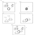
図2は,本発明のコンピュータを用いた表示装置による処理の例を説明するためのフローチャートである。図2中,Sはステップを示す。図3は,本発明のコンピュータを用いた表示装置にしたがって画像処理される過程を説明するための図である。図3Aは,キャラクタを含む2次元画像の例を示す。図3Bは,キャラクタのZ値を抽出して得られる図の例を示す。図3Cは,ポリゴンの概念図である。図3Dは,キャラクタと,陰面消去処理が施されたポリゴンとを合成した場合の画像の例を示す。図3Eは,合成された画像を示す。 FIG. 2 is a flowchart for explaining an example of processing by the display device using the computer of the present invention. In FIG. 2, S indicates a step. FIG. 3 is a diagram for explaining a process of image processing according to a display device using a computer of the present invention. FIG. 3A shows an example of a two-dimensional image including a character. FIG. 3B shows an example of a figure obtained by extracting the Z value of the character. FIG. 3C is a conceptual diagram of a polygon. FIG. 3D shows an example of an image when a character and a polygon subjected to hidden surface removal processing are combined. FIG. 3E shows the synthesized image.
本発明方法は,コンピュータを用いた動画の表示方法に関する。そして,この方法に用いられるコンピュータ(11)は,頂点座標値記憶手段(19)と,ポリゴン取得手段(23)と,前後判定用ポリゴンキャラクタZ値取得手段(25)と,Z値比較手段(27)と,陰面消去手段(29)と,画像合成手段(31)とを有する。 The present invention relates to a moving image display method using a computer. The computer (11) used in this method includes a vertex coordinate value storage means (19), a polygon acquisition means (23), a front and rear determination polygon character Z value acquisition means (25), and a Z value comparison means ( 27), hidden surface erasing means (29), and image synthesizing means (31).
この方法は,フレームごとに,以下工程を含む情報処理を行う。すなわち,この方法は,前後判定用ポリゴンキャラクタの頂点座標値を読み出す工程(S101)と,前後判定用ポリゴンキャラクタのZ値を求める工程(S102)と,3次元ポリゴンキャラクタを得る工程(S103)と,Z値比較工程(S104)と,陰面消去工程(S105)と,合成画面取得工程(S106)と,を含む。 This method performs information processing including the following steps for each frame. That is, in this method, a step of reading the vertex coordinate values of the front and rear determination polygon character (S101), a step of obtaining the Z value of the front and rear determination polygon character (S102), and a step of obtaining a three-dimensional polygon character (S103). , Z value comparison step (S104), hidden surface removal step (S105), and composite screen acquisition step (S106).
前後判定用ポリゴンキャラクタの頂点座標値を読み出す工程(S101)
前後判定用ポリゴンキャラクタの頂点座標値を読み出す工程(S101)は,頂点座標値記憶手段(19)から,2次元キャラクタ(15)を3次元ポリゴンで表した場合の前後判定用ポリゴンキャラクタ(17)の頂点座標値を読み出す工程である。この工程は,たとえば,入力装置から所定の情報が入力された場合,ROMなどの記憶装置に記憶されている複数の頂点座標値を読み出すことで達成できる。
A step of reading the vertex coordinate value of the polygon character for forward / backward determination (S101)
The step (S101) of reading out the vertex coordinate value of the front / rear determination polygon character (S101) includes a front / rear determination polygon character (17) when the two-dimensional character (15) is represented by a three-dimensional polygon from the vertex coordinate value storage means (19). This is a step of reading out the vertex coordinate values. This step can be achieved, for example, by reading a plurality of vertex coordinate values stored in a storage device such as a ROM when predetermined information is input from the input device.
頂点座標値記憶手段(19)は,2次元画像(13)中の奥行判定を要する2次元キャラクタ(15)を3次元ポリゴンで表した場合の前後判定用ポリゴンキャラクタ(17)の頂点座標値(Z,Y,Z)を記憶するための手段である。コンピュータの記憶装置が頂点座標値記憶手段として機能する。具体的な頂点座標値記憶手段として,ROMがあげられる。なお,頂点座標値記憶手段(19)は,通常複数の頂点座標値を記憶する。 The vertex coordinate value storage means (19) is a vertex coordinate value (15) of the front / rear determination polygon character (17) when the two-dimensional character (15) requiring depth determination in the two-dimensional image (13) is represented by a three-dimensional polygon. Z, Y, Z) is a means for storing. A computer storage device functions as vertex coordinate value storage means. A specific vertex coordinate value storage means is a ROM. The vertex coordinate value storage means (19) usually stores a plurality of vertex coordinate values.
2次元キャラクタ(15)は,2次元画像(13)中に存在したキャラクタである。このキャラクタは,3次元ポリゴンキャラクタと陰面消去を行うために,奥行判定を要する。図3Aで示される例では,2次元画像(13)に含まれる球(15)が2次元キャラクタ(15)である。つまり,後の工程で,この球(15)と車(21a,21b)とを陰面消去処理する。 The two-dimensional character (15) is a character that exists in the two-dimensional image (13). This character requires depth determination in order to perform hidden surface removal with a three-dimensional polygon character. In the example shown in FIG. 3A, the sphere (15) included in the two-dimensional image (13) is the two-dimensional character (15). In other words, in a later process, the sphere (15) and the cars (21a, 21b) are hidden.
図4は,図3Aの2次元画像を作成する際の例を示す図である。図4Aは,キャラクタを描画する前の背景画像(41)を示す。図4Bは,キャラクタとしての球を示す。すなわち,コンピュータを用いた表示装置を用いて,背景画像(41)やポリゴンンキャラクタ(33)を描画する。なお,図では,簡単のためポリゴンを2次元画像のように描画している。通常は,背景画像(41)とキャラクタ(33)とを合成し,ラスタライズして2次元画像を得る。その場合であっても,キャラクタ(33)のポリゴン情報は,キャラクタファイルに格納されている。よって,キャラクタファイルからキャラクタの頂点座標を読み出すことで,前後判定用ポリゴンキャラクタを抽出できる。 FIG. 4 is a diagram illustrating an example when the two-dimensional image of FIG. 3A is created. FIG. 4A shows a background image (41) before drawing a character. FIG. 4B shows a sphere as a character. That is, a background image (41) and a polygon character (33) are drawn using a display device using a computer. In the figure, for simplicity, the polygon is drawn like a two-dimensional image. Usually, the background image (41) and the character (33) are synthesized and rasterized to obtain a two-dimensional image. Even in that case, the polygon information of the character (33) is stored in the character file. Therefore, the polygon character for forward / backward determination can be extracted by reading the vertex coordinates of the character from the character file.
上記のとおり,本明細書における前後判定用ポリゴンキャラクタ(17)は,2次元キャラクタ(15)を3次元ポリゴンで表した場合の仮想的なキャラクタである。前後判定用ポリゴンキャラクタ(17)は,3次元ポリゴンキャラクタと陰面消去を行うことができればよい。このため,前後判定用ポリゴンキャラクタ(17)は,ポリゴンを表現するために必要とされる頂点座標を有していればよい。 As described above, the front-rear determination polygon character (17) in this specification is a virtual character when the two-dimensional character (15) is represented by a three-dimensional polygon. The front-rear determination polygon character (17) only needs to be able to perform hidden surface removal with a three-dimensional polygon character. For this reason, the front-rear determination polygon character (17) only needs to have vertex coordinates required for expressing the polygon.
本発明の好ましいパターンは,2次元画像(13)が,ポリゴンにより表現されるキャラクタに基づいて生成されたものに関する。そして,前後判定用ポリゴンキャラクタ(17)の頂点座標値は,2次元画像中の奥行判定を要するキャラクタをポリゴンで表現した際の複数の頂点を用いて得られたものである。 A preferred pattern of the present invention relates to a two-dimensional image (13) generated based on a character represented by a polygon. The vertex coordinate value of the polygon character for determination before and after (17) is obtained by using a plurality of vertices when a character that requires depth determination in a two-dimensional image is represented by a polygon.
前後判定用ポリゴンキャラクタのZ値を求める工程(S102)
前後判定用ポリゴンキャラクタのZ値を求める工程(S102)は,頂点座標値を用いて前後判定用ポリゴンキャラクタ(17)のZ値を求める工程である。Z値は,奥行きや深さを示す座標値である。この工程は,通常の3次元コンピュータグラフィックスにおいて用いられている変換方法を適宜用いればよい。たとえば,所定の変換行列を用いてZ値を求めてもよい。この場合,変換行列を記憶する手段と,変換行列を読み出す手段,及び変換行列を用いて座標値を変換する手段を有することで,前後判定用ポリゴンキャラクタのZ値を求めることができる。
A step of obtaining the Z value of the front / rear determination polygon character (S102)
The step of obtaining the Z value of the front / rear determination polygon character (S102) is a step of obtaining the Z value of the front / rear determination polygon character (17) using the vertex coordinate values. The Z value is a coordinate value indicating depth and depth. In this step, a conversion method used in ordinary three-dimensional computer graphics may be used as appropriate. For example, the Z value may be obtained using a predetermined transformation matrix. In this case, the Z value of the front-rear determination polygon character can be obtained by having means for storing the conversion matrix, means for reading the conversion matrix, and means for converting the coordinate values using the conversion matrix.
前後判定用ポリゴンキャラクタZ値取得手段(25)は,頂点座標値記憶手段(19)が記憶した頂点座標値から,前後判定用ポリゴンキャラクタ(17)のZ値を求めるための手段である。この手段は,たとえば,プリミティブを把握する手段,プリミティブの辺上のZ値を,頂点座標を補間することで求める手段,及びプリミティブ内部のZ値を掃引補間することで求める手段を有するものがあげられる。このようにして,ピクセルごとに前後判定用ポリゴンキャラクタのZ値を求めることができる。前後判定用ポリゴンキャラクタZ値取得手段(25)は,CPUにより実現してもよく,GPU(グラフィックチップ)により実装してもよい。 The front and rear determination polygon character Z value acquisition means (25) is a means for obtaining the Z value of the front and rear determination polygon character (17) from the vertex coordinate values stored in the vertex coordinate value storage means (19). This means includes, for example, means for grasping the primitive, means for obtaining the Z value on the edge of the primitive by interpolating the vertex coordinates, and means for obtaining the Z value inside the primitive by sweep interpolation. It is done. In this way, the Z value of the front / rear determination polygon character can be obtained for each pixel. The front-rear determination polygon character Z value acquisition means (25) may be realized by a CPU or may be implemented by a GPU (graphic chip).
求められた前後判定用ポリゴンキャラクタのZ値は,適宜記憶される。このように,前後判定用ポリゴンキャラクタのZ値が記憶されるので,この値を読み出して,3次元ポリゴンキャラクタと陰面消去を行うことができることとなる。 The obtained Z value of the front-rear determination polygon character is stored as appropriate. Thus, since the Z value of the polygon character for forward / backward determination is stored, this value can be read out and the hidden surface removal with the three-dimensional polygon character can be performed.
3次元ポリゴンキャラクタを得る工程(S103)
3次元ポリゴンキャラクタを得る工程(S103)は,ポリゴン取得手段(23)が2次元画像(13)とあわせて表示させる3次元ポリゴンキャラクタ(21)を得る工程である。この工程は,S101の前であってもよいし,S101とS102の間であってもよい。また,S101及びS102と並行して行われてもよい。この工程では,別途作成されたポリゴン情報を入手してもよい。すなわち描画装置に格納されたポリゴンを読み出してもよいし,描画装置に入力されたポリゴンを得てもよい。図3Cに示される例では,球(15)の前後を通過する車(21a,21b)が描画されている。図3Cでは,簡単のため,3次元ポリゴンキャラクタ(21)が,ポリゴン画像ではなく2次元的に描画されている。この車(21a,21b)は,2次元画像とあわせて表示させるものである。2次元画像上にポリゴンキャラクタ(21a,21b)をそのまま描画すると,2次元画像に含まれるキャラクタ(15)とポリゴンキャラクタ(21a,21b)の前後関係が不自然となる。そこで,2次元キャラクタ(15)に基づく前後判定用ポリゴンキャラクタ(17)とポリゴンキャラクタ(21a,21b)とのZ値を比較し,陰面消去処理を行う。
Step of obtaining a three-dimensional polygon character (S103)
The step of obtaining a three-dimensional polygon character (S103) is a step of obtaining a three-dimensional polygon character (21) to be displayed together with the two-dimensional image (13) by the polygon acquisition means (23). This process may be performed before S101 or between S101 and S102. Moreover, it may be performed in parallel with S101 and S102. In this process, polygon information created separately may be obtained. That is, the polygon stored in the drawing apparatus may be read, or the polygon input to the drawing apparatus may be obtained. In the example shown in FIG. 3C, cars (21a, 21b) passing through the front and rear of the sphere (15) are drawn. In FIG. 3C, for the sake of simplicity, the three-dimensional polygon character (21) is drawn two-dimensionally instead of a polygon image. The cars (21a, 21b) are displayed together with a two-dimensional image. If the polygon character (21a, 21b) is directly drawn on the two-dimensional image, the front-rear relationship between the character (15) and the polygon character (21a, 21b) included in the two-dimensional image becomes unnatural. Therefore, the Z values of the front and rear determination polygon character (17) based on the two-dimensional character (15) and the polygon character (21a, 21b) are compared, and hidden surface removal processing is performed.
ポリゴン取得手段(23)は,2次元画像(13)とあわせて表示させる3次元ポリゴンキャラクタ(21)を得るための手段である。3次元コンピュータグラフィックス用ポリゴンを作成するための装置や方法は公知である。また,3次元ポリゴンキャラクタ(21)を記憶装置に格納しておき,3次元ポリゴンキャラクタ(21)を読み出すことも公知である。 The polygon acquisition means (23) is means for obtaining a three-dimensional polygon character (21) to be displayed together with the two-dimensional image (13). Devices and methods for creating 3D computer graphics polygons are known. It is also known to store a three-dimensional polygon character (21) in a storage device and read the three-dimensional polygon character (21).
3次元ポリゴンキャラクタを得た際に,このポリゴンを表現する複数のプリミティブの頂点座標や,ピクセルごとのZ値をも得ることができる。 When a three-dimensional polygon character is obtained, the vertex coordinates of a plurality of primitives representing this polygon and the Z value for each pixel can also be obtained.
Z値比較工程(S104)
Z値比較工程(S104)は,Z値比較手段(27)が,ピクセル単位で,前後判定用ポリゴンキャラクタ(17)のZ値と3次元ポリゴンキャラクタ(21)のZ値とを比較する工程である。図5は,Z値を示す概念図である。図5では,濃淡によりZ値が表現されている。すなわち,車(21a)に比べて,車(21b)が前面に位置することがわかる。
Z value comparison process (S104)
The Z value comparison step (S104) is a step in which the Z value comparison means (27) compares the Z value of the front and rear determination polygon character (17) with the Z value of the three-dimensional polygon character (21) in units of pixels. is there. FIG. 5 is a conceptual diagram showing the Z value. In FIG. 5, the Z value is expressed by shading. That is, it can be seen that the car (21b) is located in front of the car (21a).
Z値を比較し陰面消去処理をすることは,たとえば特開平6−44384号公報などに記載されるとおり公知である。仮想キャラクタ部分のピクセルごとのZ値は,適宜格納される。また,3次元ポリゴンキャラクタのZ値も適宜に格納される。そして,対応するピクセルにおける2つのZ値を読み出してその大小を比較する。これにより,キャラクタ部分のZ値と,ポリゴンのZ値をピクセルごとに比較できることとなる。具体的には,図3Bに示される球のZ値と,図5に示される車のZ値を比較する。このZ値比較は,たとえば球の部分のみについて行ってもよい。また,Z値比較を車の部分のみ行ってもよい。さらに,球と車を合わせた部分のみについてZ値比較を行ってもよい。すなわち,Z値比較は,キャラクタ部分又はポリゴン部分のみについて行われてもよい。通常,背景画像は,奥行が深い部分にあるため,ポリゴンとの前後関係を判断しなくてよい。このような場合は,キャラクタ部分とポリゴンのみのZ値を比較することで,処理量を軽減でき,これによりリアルタイムな動画を実現できる。 Comparing Z values and performing hidden surface removal processing is known as described in, for example, Japanese Patent Laid-Open No. 6-44384. The Z value for each pixel of the virtual character portion is stored as appropriate. Also, the Z value of the three-dimensional polygon character is stored as appropriate. Then, two Z values in the corresponding pixels are read and compared in magnitude. As a result, the Z value of the character portion and the Z value of the polygon can be compared for each pixel. Specifically, the Z value of the sphere shown in FIG. 3B is compared with the Z value of the car shown in FIG. This Z-value comparison may be performed only on the sphere portion, for example. Further, the Z value comparison may be performed only on the vehicle portion. Furthermore, the Z value comparison may be performed only for the portion where the ball and the car are combined. That is, the Z value comparison may be performed only on the character portion or the polygon portion. Usually, since the background image is in a deep part, it is not necessary to determine the context with the polygon. In such a case, the processing amount can be reduced by comparing the Z values of only the character portion and the polygon, thereby realizing a real-time moving image.
Z値比較手段(27)は,前後判定用ポリゴンキャラクタZ値取得手段(25)が求めた前後判定用ポリゴンキャラクタ(17)のZ値と,ポリゴン取得手段(23)が取得したポリゴンのZ値とをピクセル単位で比較するための手段である。Z値比較手段(27)の例として,前後判定用ポリゴンキャラクタ(17)のZ値とポリゴンのZ値との除数を求めてこれにより大小を比較する比較手段を有するものがあげられる。また,前後判定用ポリゴンキャラクタ(17)のZ値とポリゴンのZ値の差を求め,求めた差の符号を用いて大小比較をするものであってもよい。 The Z value comparison means (27) includes the Z value of the front and rear determination polygon character (17) obtained by the front and rear determination polygon character Z value acquisition means (25) and the Z value of the polygon acquired by the polygon acquisition means (23). Is a means for comparing with each other in pixel units. As an example of the Z value comparison means (27), there is one having a comparison means for obtaining the divisor between the Z value of the polygon character for determination before and after (17) and the Z value of the polygon and comparing the divisor. Further, the difference between the Z value of the polygon character for determination before and after (17) and the Z value of the polygon may be obtained, and the magnitude comparison may be performed using the sign of the obtained difference.
陰面消去工程(S105)
陰面消去工程(S105)は,陰面消去手段(29)が,Z値比較手段(27)の比較結果に基づいて,3次元ポリゴンキャラクタ(21)と前後判定用ポリゴンキャラクタ(17)のうち背面に位置するものについて陰面消去を行う工程である。Z値を比較し陰面消去処理をすることは,たとえば特開平6−44384号公報などに記載されるとおり公知である。ピクセルごとに,前後判定用ポリゴンキャラクタと3次元ポリゴンキャラクタのうちZ値が大きく,奥深くに位置するもののデータを削除する。たとえば,あるピクセルにおいて,前後判定用ポリゴンキャラクタが3次元ポリゴンキャラクタの背面に位置する場合を考える。この場合,そのピクセルにおける前後判定用ポリゴンキャラクタの情報を削除する。たとえば,グラフィックチップに含まれるZバッファは,ピクセルごとに,前後判定用ポリゴンキャラクタ(17)及び3次元ポリゴンキャラクタ(21)のうち手前にあるもの(すなわち,Z値が小さいもの)のZ値を記憶する。なお,前後判定用ポリゴンキャラクタ(17)及び3次元ポリゴンキャラクタ(21)より前に別のポリゴンなどが存在する場合は,前後判定用ポリゴンキャラクタ(17)及び3次元ポリゴンキャラクタ(21)のZ値ではなく,最も手前にあるもの(すなわち最もZ値が小さいもの)のZ値がZバッファに記憶されるものが好ましい。
Hidden surface removal process (S105)
In the hidden surface erasing step (S105), the hidden surface erasing means (29) is arranged on the back of the three-dimensional polygon character (21) and the front / rear determination polygon character (17) based on the comparison result of the Z value comparing means (27). This is a process of performing hidden surface erasure on a positioned object. Comparing Z values and performing hidden surface removal processing is known as described in, for example, Japanese Patent Laid-Open No. 6-44384. For each pixel, data of the polygon character for which the Z value is large and located deeply among the front-rear determination polygon character and the three-dimensional polygon character is deleted. For example, let us consider a case where a front-rear determination polygon character is positioned behind a three-dimensional polygon character at a certain pixel. In this case, the information on the front / rear determination polygon character in the pixel is deleted. For example, the Z buffer included in the graphic chip may obtain the Z value of the front-side determination polygon character (17) and the three-dimensional polygon character (21) for each pixel (that is, the one having a small Z value). Remember. In the case where another polygon exists before the front / rear determination polygon character (17) and the three-dimensional polygon character (21), the Z values of the front / rear determination polygon character (17) and the three-dimensional polygon character (21) are present. Rather, it is preferable that the Z value of the closest one (that is, the smallest Z value) is stored in the Z buffer.
陰面消去手段(29)は,Z値比較手段(27)による比較結果に基づいて3次元ポリゴンキャラクタ(21)及び前後判定用ポリゴンキャラクタ(17)の陰面消去を行うための手段である。 The hidden surface removal means (29) is a means for performing hidden surface removal of the three-dimensional polygon character (21) and the front and rear determination polygon character (17) based on the comparison result by the Z value comparison means (27).
図6は,陰面消去後の画像例を示す図である。図6Aは,陰面消去後のポリゴン及びキャラクタの例を示す図である。図6Bは,陰面消去後のポリゴンの例を示す図である。すなわち,Z値比較の結果,ポリゴンとキャラクタの重複領域のピクセルでは,車(21a)が最背面に位置し,球(15)が中位に位置し,車(21b)が最前面に位置する。このZ値比較の結果に基づいて,陰面消去処理を行う。すなわち,車(21a)と球(15)との重複領域においては,Z値比較の結果,車(21a)の情報が削除される。一方,車(21b)と球(15)との重複領域においては,Z値比較の結果,球(15)の情報が削除される。 FIG. 6 is a diagram illustrating an example of an image after hidden surface removal. FIG. 6A is a diagram illustrating an example of polygons and characters after hidden surface removal. FIG. 6B is a diagram illustrating an example of a polygon after hidden surface removal. That is, as a result of the Z value comparison, in the pixel in the overlapping area of the polygon and the character, the car (21a) is located at the backmost position, the sphere (15) is located at the middle position, and the car (21b) is located at the forefront position. . The hidden surface removal process is performed based on the result of the Z value comparison. That is, in the overlap region between the car (21a) and the sphere (15), the information on the car (21a) is deleted as a result of the Z value comparison. On the other hand, in the overlapping region of the car (21b) and the sphere (15), the information of the sphere (15) is deleted as a result of the Z value comparison.
合成画面取得工程(S106)
合成画面取得工程(S106)は,画像合成手段(31)が,2次元画像(13)に,陰面消去手段(29)により陰面消去処理が施された3次元ポリゴンキャラクタ(21)及び前後判定用ポリゴンキャラクタ(17)を合成して,合成画面を得る工程である。たとえば,図6Aの画像と図5の画像を合成すると,図3Eに示される合成画像を得ることができる。一方,図6Bの画像と図3Aの画像を合成しても,図3Eに示される合成画像を得ることができる。
Synthetic screen acquisition process (S106)
In the composite screen acquisition step (S106), the image compositing means (31) uses the two-dimensional image (13) subjected to the hidden surface erasure processing by the hidden surface erasing means (29) and the front-rear determination. This is a step of combining the polygon character (17) to obtain a combined screen. For example, when the image of FIG. 6A and the image of FIG. 5 are combined, the combined image shown in FIG. 3E can be obtained. On the other hand, even if the image of FIG. 6B and the image of FIG. 3A are combined, the combined image shown in FIG. 3E can be obtained.
合成された画像は,適宜ラスタライズされ,2次元画像として出力されればよい。そして,このように出力された2次元画像は,フレームバッファなどに格納され,表示装置により表示される。 The synthesized image may be appropriately rasterized and output as a two-dimensional image. The two-dimensional image output in this way is stored in a frame buffer or the like and displayed on a display device.
画像合成手段(31)は,2次元画像(13)に,陰面消去手段(29)により陰面消去処理が施された3次元ポリゴンキャラクタ(21)及び前後判定用ポリゴンキャラクタ(17)を合成して,合成画面を得るための手段である。 The image composition means (31) synthesizes the two-dimensional image (13) with the three-dimensional polygon character (21) and the front-rear determination polygon character (17) subjected to the hidden surface removal processing by the hidden surface removal means (29). , A means to obtain a composite screen.
本発明は,コンピュータを用いた表示装置などに関する。そして,コンピュータは,入出力装置,記憶装置,演算装置,制御装置を具備する。そして,各要素はバスなどで接続され,情報の授受を行うことができるようにされている。このようなコンピュータとして,グラフィックプロセッサを有するものがあげられる。本発明のプログラムは,たとえば,制御プログラムとして記憶装置に格納される。本発明の表示装置は,たとえば,以下のように動作する。入力装置から何らかの指示が入力される。すると,制御装置は,記憶装置に格納された制御プログラムを読み出す。そして,入力情報を用いるとともに,適宜記憶装置に記憶された情報を読み出し,演算装置で所定の演算を行う。そして,演算装置で行った演算結果を記憶装置に記憶する。そして,制御装置は,記憶装置に記憶された演算結果を入出力装置から出力する。 The present invention relates to a display device using a computer. The computer includes an input / output device, a storage device, an arithmetic device, and a control device. Each element is connected by a bus or the like so that information can be exchanged. An example of such a computer is a computer having a graphic processor. The program of the present invention is stored in a storage device as a control program, for example. The display device of the present invention operates as follows, for example. Some instruction is input from the input device. Then, the control device reads the control program stored in the storage device. And while using input information, the information memorize | stored in the memory | storage device suitably is read, and a predetermined calculation is performed with an arithmetic unit. And the calculation result performed with the arithmetic unit is memorize | stored in a memory | storage device. Then, the control device outputs the calculation result stored in the storage device from the input / output device.
本発明は,上記のコンピュータを用いた表示装置を搭載した遊技機をも提供する。遊技機として,パチンコ,スロットマシーン,パチスロ,ゲーム機,及びゲーム付携帯電話があげられる。これらの遊技機は,コンピュータグラフィックスを表示するモニタが存在する。よって,本発明のコンピュータを用いた表示装置を搭載した遊技機は,モニタからリアルタイムなグラフィック動画を表示できる。 The present invention also provides a gaming machine equipped with a display device using the above computer. Examples of gaming machines include pachinko machines, slot machines, pachislot machines, game machines, and mobile phones with games. These gaming machines have a monitor that displays computer graphics. Therefore, the gaming machine equipped with the display device using the computer of the present invention can display a real-time graphic moving image from the monitor.
本発明のプログラムは,コンピュータを,頂点座標値記憶手段(19),ポリゴン取得手段(23),前後判定用ポリゴンキャラクタZ値取得手段(25),Z値比較手段(27),陰面消去手段(29),及び画像合成手段(31)として機能させるためのプログラムに関する。これらの手段は,先に説明したとおりである。また,本発明は,このプログラムを格納したコンピュータ読み取り可能な情報記録媒体をも提供する。情報記録媒体として,ROM,CD−ROM,DVD,ハードディスクがあげられる。 The program according to the present invention includes a computer, a vertex coordinate value storage means (19), a polygon acquisition means (23), a front and rear determination polygon character Z value acquisition means (25), a Z value comparison means (27), a hidden surface removal means ( 29), and a program for causing the image composition means (31) to function. These means are as described above. The present invention also provides a computer-readable information recording medium storing this program. Examples of the information recording medium include ROM, CD-ROM, DVD, and hard disk.
本発明の好ましいパターンは,表示装置がZバッファを含むグラフィックチップと,グラフィックチップとバスにより接続されたROMとを含むものである。たとえば,グラフィックチップとバスにより接続されたROMに2次元画像の圧縮データを格納することで,グラフィックチップのデコード機能によりデータを読み取ることとデコードとを連続して実行できる。また,これらと並行して,3次元ポリゴンキャラクタを描画できる。さらに,グラフィックチップなどに,Zバッファを内蔵することができるため,きわめて高速なアクセスを実現できた。たとえば,ROMが頂点座標値記憶手段(19)として機能する。そして,たとえば,グラフィックチップに含まれるZバッファは,ピクセルごとに,前後判定用ポリゴンキャラクタ(17)及び3次元ポリゴンキャラクタ(21)のうち手前にあるもの(すなわち,Z値が小さいもの)のZ値を記憶する。なお,前後判定用ポリゴンキャラクタ(17)及び3次元ポリゴンキャラクタ(21)より前に別のポリゴンなどが存在する場合は,前後判定用ポリゴンキャラクタ(17)及び3次元ポリゴンキャラクタ(21)のZ値ではなく,最も手前にあるもの(すなわち最もZ値が小さいもの)のZ値がZバッファに記憶されるものが好ましい。 In a preferred pattern of the present invention, the display device includes a graphic chip including a Z buffer, and a ROM connected to the graphic chip by a bus. For example, by storing compressed data of a two-dimensional image in a ROM connected to the graphic chip via a bus, the data can be read and decoded continuously by the graphic chip decoding function. In parallel with these, a three-dimensional polygon character can be drawn. In addition, the Z-buffer can be built in a graphic chip, etc., so extremely fast access can be realized. For example, the ROM functions as vertex coordinate value storage means (19). For example, the Z buffer included in the graphic chip is a Z buffer of the front-side determination polygon character (17) and the three-dimensional polygon character (21) for each pixel (that is, the one having a small Z value). Store the value. In the case where another polygon exists before the front / rear determination polygon character (17) and the three-dimensional polygon character (21), the Z values of the front / rear determination polygon character (17) and the three-dimensional polygon character (21) are present. Rather, it is preferable that the Z value of the closest one (that is, the smallest Z value) is stored in the Z buffer.
図7は,実施例における表示装置のブロック図である。図7に示されるように,この表示装置は,CPUと接続されたグラフィックチップ及び第1のROMと,グラフィックチップに接続された第2のROM,フレームバッファ及びモニタとを含む。そして,グラフィックチップはZバッファを含んでいる。グラフィックチップがZバッファを含むので,高速なアクセスを実現できた。以下,本発明の方法の例を説明する。 FIG. 7 is a block diagram of the display device in the embodiment. As shown in FIG. 7, the display device includes a graphic chip and a first ROM connected to the CPU, and a second ROM, a frame buffer and a monitor connected to the graphic chip. The graphic chip includes a Z buffer. Since the graphic chip includes a Z buffer, high-speed access can be realized. Hereinafter, an example of the method of the present invention will be described.
まず,MAYA(登録商標),3DSTUDIOMAX(登録商標)などの3D描画ソフトを用いて3次元モデル(3次元ポリゴンキャラクタ)を制作する。モデルや背景を作成してモーション付けをし,一連の動画を含む3Dファイルを完成する。そして,3Dファイルをレンダリングし,フレーム毎の2次元連続画像を得る。3Dファイルを2Dファイルにする変換する際には合成させる図柄などの3Dポリゴンキャラクタを削除(非表示)して,レンダリングして2D画像化する。さらに,その2D画像データを,データ容量を削減する為に圧縮することが好ましい。圧縮のフォーマットは,公知のものを適宜利用できる。 First, a 3D model (3D polygon character) is created using 3D drawing software such as MAYA (registered trademark), 3DSTUDIOMAX (registered trademark), or the like. Create a model and background, add motion, and complete a 3D file containing a series of videos. Then, the 3D file is rendered to obtain a two-dimensional continuous image for each frame. When converting a 3D file to a 2D file, a 3D polygon character such as a pattern to be synthesized is deleted (not displayed) and rendered to form a 2D image. Furthermore, it is preferable to compress the 2D image data in order to reduce the data capacity. A known compression format can be used as appropriate.
コンバータを用いて,先の完成した3Dファイルから,システムのフォーマットに合わせて,前後判定用ポリゴンの頂点座標データ,モーションデータを抽出する。これにより,ムービー中のキャラクタのZ値判定用のデータ抽出を行う。取得した前後判定用ポリゴンの頂点データを,色情報無し(透明)の3Dポリゴンキャラクタデータとして扱う。合成させる図柄等の3Dポリゴンキャラクタ情報も,元のファイルより,コンバートする。この3Dポリゴンキャラクタ情報は,描画・表示させる色・画像情報付で取得して,表示させる3Dポリゴンキャラクタデータとして扱う。画像情報を入れ替える事により,異なった図柄(数字等)を表示でき,固定の2Dムービーの中に変更可能な3Dポリゴンを合成できることとなる。2Dムービーの再生を行う圧縮データのデコード性能と3Dリアルタイムの描画性能が高い程,高いフレームレートで多くの3Dポリゴンキャラクタを表示させることができる。 Using the converter, the vertex coordinate data and motion data of the front / rear determination polygon are extracted from the previously completed 3D file according to the system format. Thereby, data for determining the Z value of the character in the movie is extracted. The acquired vertex data of the front-rear determination polygon is treated as 3D polygon character data without color information (transparent). 3D polygon character information such as symbols to be synthesized is also converted from the original file. This 3D polygon character information is acquired with color / image information to be drawn / displayed, and handled as 3D polygon character data to be displayed. By changing the image information, different designs (numbers, etc.) can be displayed, and a changeable 3D polygon can be synthesized in a fixed 2D movie. The higher the decoding performance of compressed data for reproducing a 2D movie and the 3D real-time rendering performance, the more 3D polygon characters can be displayed at a higher frame rate.
この後,データをROMに書き込む。 Thereafter, the data is written into the ROM.
実施例1は,3Dポリゴンで制作されたデータをレンダリングして2D画像とした場合に,元情報として,キャラクタ毎に,ポリゴン座標情報やモーションの情報があるために,比較的容易に実現される。しかし,アニメーションや,カメラで撮られた実写映像に,3Dポリゴンのキャラクタを合成させることもできる。アニメーションや実写映像中の対象キャラクタに,座標情報を割り当てる手段としては,画像認識の手段で抽出する方法や,手作業で対象キャラクタと重なり合うような同一モデルを制作して,同一の動きを割り当ててもよい。 In the first embodiment, when the data produced by the 3D polygon is rendered into a 2D image, since the original information includes polygon coordinate information and motion information for each character, it can be realized relatively easily. . However, 3D polygon characters can be combined with animations or live-action images taken with a camera. Coordinate information can be assigned to target characters in animations and live-action images by extracting them using image recognition, or by creating the same model that overlaps the target character manually and assigning the same movement. Also good.
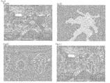
図8は,本発明のコンピュータを用いた表示装置にしたがって画像処理される過程を説明するための図である。図8Aは,キャラクタを含む2次元画像の例を示す。図8Bは,キャラクタのZ値を抽出して得られる前後判定用ポリゴンキャラクタの例を示す。図8Cは,3次元ポリゴンキャラクタの例を示す。図8Dは,陰面消去処理が施されたポリゴンを合成した場合の画像の例を示す。 FIG. 8 is a diagram for explaining a process of image processing according to a display device using a computer of the present invention. FIG. 8A shows an example of a two-dimensional image including a character. FIG. 8B shows an example of a front / rear determination polygon character obtained by extracting the Z value of the character. FIG. 8C shows an example of a three-dimensional polygon character. FIG. 8D shows an example of an image when a polygon subjected to hidden surface removal processing is synthesized.
まず,2次元画像中の奥行判定を要するキャラクタを抽出する。図8Aで示される例では,2次元画像に含まれるモンスターが抽出される。この例では,3次元ポリゴンを用いて3次元コンピュータグラフィックを作成し,それを2次元データに変換している。そこで,2次元データに変換する前の3次元ポリゴンの頂点座標情報を取得した。これにより,2次元画像に含まれるキャラクタ(モンスター)を抽出した。具体的には,3次元ポリゴンをレンダリングして2次元画像を生成する際に,ポリゴンの複数の頂点座標値をレンダリング画像とは別に記憶した。 First, a character that requires depth determination is extracted from the two-dimensional image. In the example shown in FIG. 8A, monsters included in the two-dimensional image are extracted. In this example, a three-dimensional computer graphic is created using a three-dimensional polygon and converted to two-dimensional data. Therefore, the vertex coordinate information of the 3D polygon before being converted into 2D data was acquired. Thereby, the character (monster) contained in the two-dimensional image was extracted. Specifically, when a two-dimensional image is generated by rendering a three-dimensional polygon, a plurality of vertex coordinate values of the polygon are stored separately from the rendered image.
次に,仮想キャラクタ部分のZ値を得る。図8Bに示される例では,前後判定用ポリゴンキャラクタが,2次元画像のキャラクタ部分以外の領域と区別されている。すなわち,図8Bに示される例では,キャラクタ部分のZ値が周囲の部分のZ値に比べて小さい。このため,キャラクタ部分が薄く表示される。 Next, the Z value of the virtual character part is obtained. In the example shown in FIG. 8B, the front / rear determination polygon character is distinguished from an area other than the character portion of the two-dimensional image. That is, in the example shown in FIG. 8B, the Z value of the character part is smaller than the Z value of the surrounding part. For this reason, the character portion is displayed lightly.
次に,2次元画像に絡ませる3次元コンピュータグラフィックス用ポリゴンを作成した。本実施例では,描画装置の記憶装置に格納されたポリゴンを読み出した。図8Cに示される例では,3次元ポリゴンキャラクタとして,2次元キャラクタ(モンスター)の周りを旋廻する複数の数字プレートが描画されている。この3次元ポリゴンキャラクタは,2次元画像とあわせて表示させるものである。2次元画像上にポリゴンをそのまま描画すると,2次元画像に含まれるキャラクタとポリゴンの前後関係が不自然となる。そこで,3次元ポリゴンキャラクタと前後判定用ポリゴンキャラクタとのZ値を比較し,陰面消去処理を行った。 Next, a polygon for three-dimensional computer graphics to be entangled with a two-dimensional image was created. In this embodiment, the polygon stored in the storage device of the drawing apparatus is read out. In the example shown in FIG. 8C, a plurality of number plates that rotate around a two-dimensional character (monster) are drawn as a three-dimensional polygon character. This 3D polygon character is displayed together with the 2D image. If a polygon is drawn as it is on a two-dimensional image, the front-rear relationship between the character and the polygon included in the two-dimensional image becomes unnatural. Therefore, the Z values of the three-dimensional polygon character and the front and rear determination polygon character were compared, and hidden surface removal processing was performed.
2次元画像と,陰面消去処理が施された画像(ポリゴン及びキャラクタ)とを合成した(ステップ107)。図8Dに,合成画像の例を示す。 The two-dimensional image and the image (polygon and character) that have been subjected to hidden surface removal processing were synthesized (step 107). FIG. 8D shows an example of a composite image.
次に,2次元画像の全てのZ値を持たせ,陰面消去を行い,合成画像を得る場合のデータ量と,本発明に基づいて画像処理を行った場合のデータ量とを比較する計算を行った。その結果を図9に示す。すなわち,図9は,2D画像の全ピクセルに対して4byteのZ値を持たせて陰面消去処理を行った場合の1フレーム当たりのデータ量と,本発明に基づいて画像処理を行った場合の1フレーム当たりのデータ量を示すグラフである。 Next, a calculation for comparing all the Z values of the two-dimensional image, performing hidden surface removal, and obtaining the composite image and the data amount when performing image processing based on the present invention is performed. went. The result is shown in FIG. That is, FIG. 9 shows the amount of data per frame when the hidden surface removal processing is performed by giving a 4-byte Z value to all pixels of the 2D image, and when the image processing is performed according to the present invention. It is a graph which shows the data amount per frame.
図9から,全ピクセルに対してZ値を持つ場合は,特に解像度が大きくなるにしたがってデータ量が大きくなることがわかる。これに対し,本発明の画像合成方法によれば,解像度が大きくなってもデータ量が変化しないことがわかる。よって,本発明は,特に高解像度モードにおける画像処理に有効であることがわかる。 From FIG. 9, it can be seen that when all the pixels have Z values, the amount of data increases especially as the resolution increases. In contrast, according to the image composition method of the present invention, it can be seen that the amount of data does not change even when the resolution increases. Therefore, it can be seen that the present invention is particularly effective for image processing in the high resolution mode.
本発明は,コンピュータグラフィックスなどの分野において好適に利用されうる。 The present invention can be suitably used in fields such as computer graphics.
11 コンピュータ; 13 2次元画像; 15 2次元キャラクタ; 17 前後判定用ポリゴンキャラクタ; 19 頂点座標値記憶手段; 21 3次元ポリゴンキャラクタ; 23 ポリゴン取得手段; 25 前後判定用ポリゴンキャラクタZ値取得手段; 27 Z値比較手段; 29 陰面消去手段; 31画像合成手段 11 computer; 13 two-dimensional image; 15 two-dimensional character; 17 front and rear determination polygon character; 19 vertex coordinate value storage means; 21 three-dimensional polygon character; 23 polygon acquisition means; 25 front and rear determination polygon character Z value acquisition means; Z value comparison means; 29 hidden surface removal means; 31 image composition means
Claims (7)
前記コンピュータ(11)は,
2次元画像(13)中の奥行判定を要する2次元キャラクタ(15)を3次元ポリゴンで表した場合の前後判定用ポリゴンキャラクタ(17)の頂点座標値を記憶する頂点座標値記憶手段(19)と,
前記2次元画像(13)とあわせて表示させる3次元ポリゴンキャラクタ(21)を得るポリゴン取得手段(23)と,
前記頂点座標値記憶手段(19)が記憶した前記頂点座標値から,前記前後判定用ポリゴンキャラクタ(17)のZ値を求める,前後判定用ポリゴンキャラクタZ値取得手段(25)と,
前記前後判定用ポリゴンキャラクタZ値取得手段(25)が求めた前記前後判定用ポリゴンキャラクタ(17)のZ値と,前記ポリゴン取得手段(23)が取得したポリゴンのZ値とをピクセル単位で比較するZ値比較手段(27)と,
前記Z値比較手段(27)による比較結果に基づいて前記3次元ポリゴンキャラクタ(21)及び前記前後判定用ポリゴンキャラクタ(17)の陰面消去を行う陰面消去手段(29)と,
前記2次元画像(13)に,前記陰面消去手段(29)により陰面消去処理が施された前記3次元ポリゴンキャラクタ(21)及び前記前後判定用ポリゴンキャラクタ(17)を合成して,合成画面を得る画像合成手段(31)と,
を具備し,
前記前後判定用ポリゴンキャラクタ(17)は座標情報のみにより構成され,
フレームごとに,
前記頂点座標値記憶手段(19)から,前記2次元キャラクタ(15)を3次元ポリゴンで表した場合の前後判定用ポリゴンキャラクタ(17)の頂点座標値を読み出す工程と,
前記頂点座標値を用いて前後判定用ポリゴンキャラクタ(17)のZ値を求める工程と,
前記ポリゴン取得手段(23)が前記2次元画像(13)とあわせて表示させる3次元ポリゴンキャラクタ(21)を得る工程と,
前記Z値比較手段(27)が,ピクセル単位で,前記前後判定用ポリゴンキャラクタ(17)のZ値と前記3次元ポリゴンキャラクタ(21)のZ値とを比較する工程と,
前記陰面消去手段(29)が,前記Z値比較手段(27)の比較結果に基づいて,前記3次元ポリゴンキャラクタ(21)と前記前後判定用ポリゴンキャラクタ(17)のうち背面に位置するものについて陰面消去を行う工程と,
前記画像合成手段(31)が,前記2次元画像(13)に,前記陰面消去手段(29)により陰面消去処理が施された前記3次元ポリゴンキャラクタ(21)及び前記前後判定用ポリゴンキャラクタ(17)を合成して,合成画面を得る工程と,
を含む,
コンピュータを用いた動画の表示方法。 A video display method using a computer (11),
The computer (11)
Vertex coordinate value storage means (19) for storing the vertex coordinate value of the front and rear determination polygon character (17) when the two-dimensional character (15) requiring depth determination in the two-dimensional image (13) is represented by a three-dimensional polygon. When,
Polygon acquisition means (23) for obtaining a three-dimensional polygon character (21) to be displayed together with the two-dimensional image (13);
A front / rear determination polygon character Z value acquisition means (25) for obtaining a Z value of the front / rear determination polygon character (17) from the vertex coordinate values stored by the vertex coordinate value storage means (19);
The Z value of the front / rear determination polygon character (17) obtained by the front / rear determination polygon character Z value acquisition means (25) and the Z value of the polygon acquired by the polygon acquisition means (23) are compared in pixel units. Z value comparison means (27) to perform,
A hidden surface removing means (29) for performing hidden surface removal of the three-dimensional polygon character (21) and the front-rear determination polygon character (17) based on the comparison result by the Z value comparing means (27);
The two-dimensional image (13) is combined with the three-dimensional polygon character (21) and the front-rear determination polygon character (17) that have been subjected to hidden surface removal processing by the hidden surface removal means (29), and a combined screen is displayed. Obtaining image composition means (31);
Comprising
The front / rear determination polygon character (17) is composed only of coordinate information,
For each frame,
Reading from the vertex coordinate value storage means (19) the vertex coordinate value of the front-rear determination polygon character (17) when the two-dimensional character (15) is represented by a three-dimensional polygon;
Obtaining the Z value of the front-rear determination polygon character (17) using the vertex coordinate values;
Obtaining a three-dimensional polygon character (21) to be displayed together with the two-dimensional image (13) by the polygon acquisition means (23);
The Z value comparing means (27) comparing the Z value of the front-rear determination polygon character (17) with the Z value of the three-dimensional polygon character (21) in units of pixels;
Based on the comparison result of the Z value comparison means (27), the hidden surface removal means (29) is located behind the three-dimensional polygon character (21) and the front / rear determination polygon character (17). A hidden surface removal process;
The image synthesizing means (31) and the two-dimensional image (13) subjected to the hidden surface erasure processing by the hidden surface erasing means (29) and the front-rear determination polygon character (17). ) To obtain a composite screen,
including,
A video display method using a computer.
2次元画像(13)中の奥行判定を要する2次元キャラクタ(15)を3次元ポリゴンで表した場合の前後判定用ポリゴンキャラクタ(17)の頂点座標値を記憶する頂点座標値記憶手段(19)と,
前記2次元画像(13)とあわせて表示させる3次元ポリゴンキャラクタ(21)を得るポリゴン取得手段(23)と,
前記頂点座標値記憶手段(19)が記憶した前記頂点座標値から,前記前後判定用ポリゴンキャラクタ(17)のZ値を求める,前後判定用ポリゴンキャラクタZ値取得手段(25)と,
前記前後判定用ポリゴンキャラクタZ値取得手段(25)が求めた前記前後判定用ポリゴンキャラクタ(17)のZ値と,前記ポリゴン取得手段(23)が取得したポリゴンのZ値とをピクセル単位で比較するZ値比較手段(27)と,
前記Z値比較手段(27)による比較結果に基づいて前記3次元ポリゴンキャラクタ(21)及び前記前後判定用ポリゴンキャラクタ(17)の陰面消去を行う陰面消去手段(29)と,
前記2次元画像(13)に,前記陰面消去手段(29)により陰面消去処理が施された前記3次元ポリゴンキャラクタ(21)及び前記前後判定用ポリゴンキャラクタ(17)を合成して,合成画面を得る画像合成手段(31)と,
を具備し,
前記前後判定用ポリゴンキャラクタ(17)は座標情報のみにより構成される,
表示装置。 A display device using a computer (11),
Vertex coordinate value storage means (19) for storing the vertex coordinate value of the front and rear determination polygon character (17) when the two-dimensional character (15) requiring depth determination in the two-dimensional image (13) is represented by a three-dimensional polygon. When,
Polygon acquisition means (23) for obtaining a three-dimensional polygon character (21) to be displayed together with the two-dimensional image (13);
A front / rear determination polygon character Z value acquisition means (25) for obtaining a Z value of the front / rear determination polygon character (17) from the vertex coordinate values stored by the vertex coordinate value storage means (19);
The Z value of the front / rear determination polygon character (17) obtained by the front / rear determination polygon character Z value acquisition means (25) and the Z value of the polygon acquired by the polygon acquisition means (23) are compared in pixel units. Z value comparison means (27) to perform,
A hidden surface removing means (29) for performing hidden surface removal of the three-dimensional polygon character (21) and the front-rear determination polygon character (17) based on the comparison result by the Z value comparing means (27);
The two-dimensional image (13) is combined with the three-dimensional polygon character (21) and the front-rear determination polygon character (17) that have been subjected to hidden surface removal processing by the hidden surface removal means (29), and a combined screen is displayed. Obtaining image composition means (31);
Comprising
The front-rear determination polygon character (17) is composed only of coordinate information.
Display device.
ポリゴンにより表現される前記キャラクタに基づいて生成されたものであり,
前後判定用ポリゴンキャラクタ(17)の頂点座標値は,前記キャラクタをポリゴンで表現した際の複数の頂点を用いて得られたものである請求項2に記載の表示装置。 The two-dimensional image (13)
Generated based on the character represented by the polygon,
The display device according to claim 2, wherein the vertex coordinate value of the front / rear determination polygon character (17) is obtained by using a plurality of vertices when the character is represented by a polygon.
前記グラフィックチップとバスにより接続されたROMとを含み,
前記ROMが前記頂点座標値記憶手段(19)として機能し,
前記Z値比較手段(27)は,前記前後判定用ポリゴンキャラクタ(17)のZ値及び前記ポリゴンのZ値を比較し,
前記グラフィックチップに含まれるZバッファは,
ピクセルごとに,前記前後判定用ポリゴンキャラクタ(17)及び前記3次元ポリゴンキャラクタ(21)のうち,手前にあるもののZ値を記憶する,
請求項2に記載の表示装置。 A graphics chip including a Z buffer;
Including the graphic chip and a ROM connected by a bus;
The ROM functions as the vertex coordinate value storage means (19),
The Z value comparison means (27) compares the Z value of the polygon character for determination before and after (17) and the Z value of the polygon,
The Z buffer included in the graphic chip is:
For each pixel, the Z value of the front / rear determination polygon character (17) and the three-dimensional polygon character (21) of the front one is stored.
The display device according to claim 2.
2次元画像(13)中の奥行判定を要する2次元キャラクタ(15)を3次元ポリゴンで表した場合の前後判定用ポリゴンキャラクタ(17)の頂点座標値を記憶する頂点座標値記憶手段(19)と,
前記2次元画像(13)とあわせて表示させる3次元ポリゴンキャラクタ(21)を得るポリゴン取得手段(23)と,
前記頂点座標値記憶手段(19)が記憶した前記頂点座標値から,前記前後判定用ポリゴンキャラクタ(17)のZ値を求める,前後判定用ポリゴンキャラクタZ値取得手段(25)と,
前記前後判定用ポリゴンキャラクタZ値取得手段(25)が求めた前記前後判定用ポリゴンキャラクタ(17)のZ値と,前記ポリゴン取得手段(23)が取得したポリゴンのZ値とをピクセル単位で比較するZ値比較手段(27)と,
前記Z値比較手段(27)による比較結果に基づいて前記3次元ポリゴンキャラクタ(21)及び前記前後判定用ポリゴンキャラクタ(17)の陰面消去を行う陰面消去手段(29)と,
前記2次元画像(13)に,前記陰面消去手段(29)により陰面消去処理が施された前記3次元ポリゴンキャラクタ(21)及び前記前後判定用ポリゴンキャラクタ(17)を合成して,合成画面を得る画像合成手段(31)と,
して機能させ,
前記前後判定用ポリゴンキャラクタ(17)は座標情報のみにより構成される,
プログラム。 Computer
Vertex coordinate value storage means (19) for storing the vertex coordinate value of the front and rear determination polygon character (17) when the two-dimensional character (15) requiring depth determination in the two-dimensional image (13) is represented by a three-dimensional polygon. When,
Polygon acquisition means (23) for obtaining a three-dimensional polygon character (21) to be displayed together with the two-dimensional image (13);
A front / rear determination polygon character Z value acquisition means (25) for obtaining a Z value of the front / rear determination polygon character (17) from the vertex coordinate values stored by the vertex coordinate value storage means (19);
The Z value of the front / rear determination polygon character (17) obtained by the front / rear determination polygon character Z value acquisition means (25) and the Z value of the polygon acquired by the polygon acquisition means (23) are compared in pixel units. Z value comparison means (27) to perform,
A hidden surface removing means (29) for performing hidden surface removal of the three-dimensional polygon character (21) and the front-rear determination polygon character (17) based on the comparison result by the Z value comparing means (27);
The two-dimensional image (13) is combined with the three-dimensional polygon character (21) and the front-rear determination polygon character (17) that have been subjected to hidden surface removal processing by the hidden surface removal means (29), and a combined screen is displayed. Obtaining image composition means (31);
To function,
The front-rear determination polygon character (17) is composed only of coordinate information.
program.
A computer-readable information recording medium storing the program according to claim 6.
Priority Applications (1)
| Application Number | Priority Date | Filing Date | Title |
|---|---|---|---|
| JP2008210387A JP4339390B1 (en) | 2008-08-19 | 2008-08-19 | Movie display device using computer, display method, program, and information recording medium |
Applications Claiming Priority (1)
| Application Number | Priority Date | Filing Date | Title |
|---|---|---|---|
| JP2008210387A JP4339390B1 (en) | 2008-08-19 | 2008-08-19 | Movie display device using computer, display method, program, and information recording medium |
Related Child Applications (1)
| Application Number | Title | Priority Date | Filing Date |
|---|---|---|---|
| JP2009078226A Division JP2010049672A (en) | 2009-03-27 | 2009-03-27 | Device and method for displaying moving image using computer, program, and information recording medium |
Publications (2)
| Publication Number | Publication Date |
|---|---|
| JP4339390B1 JP4339390B1 (en) | 2009-10-07 |
| JP2010049302A true JP2010049302A (en) | 2010-03-04 |
Family
ID=41253437
Family Applications (1)
| Application Number | Title | Priority Date | Filing Date |
|---|---|---|---|
| JP2008210387A Expired - Fee Related JP4339390B1 (en) | 2008-08-19 | 2008-08-19 | Movie display device using computer, display method, program, and information recording medium |
Country Status (1)
| Country | Link |
|---|---|
| JP (1) | JP4339390B1 (en) |
-
2008
- 2008-08-19 JP JP2008210387A patent/JP4339390B1/en not_active Expired - Fee Related
Also Published As
| Publication number | Publication date |
|---|---|
| JP4339390B1 (en) | 2009-10-07 |
Similar Documents
| Publication | Publication Date | Title |
|---|---|---|
| EP1642625B1 (en) | Video game device and image processing program | |
| JP3725524B2 (en) | Method for generating computer display image and computer processing system and graphics processor for generating image data | |
| CN101281656B (en) | Method and apparatus for mapping texture onto 3-dimensional object model | |
| US7104891B2 (en) | Game machine and game program for displaying a first object casting a shadow formed by light from a light source on a second object on a virtual game space | |
| JP4917346B2 (en) | Game image processing program and game image processing apparatus | |
| JP3625184B2 (en) | 3D image processing method and apparatus for game, readable recording medium recording game 3D image processing program, and video game apparatus | |
| JP2004005452A (en) | Image processor, image processing method, semiconductor device, computer program and record medium | |
| JP2006195882A (en) | Program, information storage medium and image generation system | |
| JP2002140722A (en) | Device and method for plotting image removing aliasing | |
| JP4193979B2 (en) | Shadow volume generation program and game device | |
| JP4749198B2 (en) | Program, information storage medium, and image generation system | |
| JP2002133438A (en) | Three-dimensional graphic plotting device, three- dimensional graphic plotting method, and recording medium capable of reading with three-dimensional polygon data recorded computer | |
| JP4995054B2 (en) | GAME PROGRAM, RECORDING MEDIUM CONTAINING THE GAME PROGRAM, AND COMPUTER | |
| JP4339390B1 (en) | Movie display device using computer, display method, program, and information recording medium | |
| JP2009205522A (en) | Program, information storage medium, and information conversion system | |
| JP4231684B2 (en) | GAME DEVICE AND GAME PROGRAM | |
| JP2010049672A (en) | Device and method for displaying moving image using computer, program, and information recording medium | |
| JP2011215724A (en) | Program, information storage medium, and image generation system | |
| JP4754385B2 (en) | Program, information recording medium, and image generation system | |
| EP1249791B1 (en) | 3-D game image processing method and device for drawing border lines | |
| JP2000056750A (en) | Image generating device and image generating method | |
| JP4847572B2 (en) | Image processing apparatus, image processing apparatus control method, and program | |
| JP2010231364A (en) | Image generation system, program and information recording medium | |
| JP4476040B2 (en) | Program, information storage medium, and image generation system | |
| JP3745152B2 (en) | Image display device |
Legal Events
| Date | Code | Title | Description |
|---|---|---|---|
| TRDD | Decision of grant or rejection written | ||
| A01 | Written decision to grant a patent or to grant a registration (utility model) |
Free format text: JAPANESE INTERMEDIATE CODE: A01 Effective date: 20090629 |
|
| A01 | Written decision to grant a patent or to grant a registration (utility model) |
Free format text: JAPANESE INTERMEDIATE CODE: A01 |
|
| A61 | First payment of annual fees (during grant procedure) |
Free format text: JAPANESE INTERMEDIATE CODE: A61 Effective date: 20090701 |
|
| R150 | Certificate of patent or registration of utility model |
Free format text: JAPANESE INTERMEDIATE CODE: R150 |
|
| FPAY | Renewal fee payment (event date is renewal date of database) |
Free format text: PAYMENT UNTIL: 20120710 Year of fee payment: 3 |
|
| S531 | Written request for registration of change of domicile |
Free format text: JAPANESE INTERMEDIATE CODE: R313531 |
|
| S533 | Written request for registration of change of name |
Free format text: JAPANESE INTERMEDIATE CODE: R313533 |
|
| FPAY | Renewal fee payment (event date is renewal date of database) |
Free format text: PAYMENT UNTIL: 20120710 Year of fee payment: 3 |
|
| R350 | Written notification of registration of transfer |
Free format text: JAPANESE INTERMEDIATE CODE: R350 |
|
| S111 | Request for change of ownership or part of ownership |
Free format text: JAPANESE INTERMEDIATE CODE: R313111 |
|
| FPAY | Renewal fee payment (event date is renewal date of database) |
Free format text: PAYMENT UNTIL: 20130710 Year of fee payment: 4 |
|
| FPAY | Renewal fee payment (event date is renewal date of database) |
Free format text: PAYMENT UNTIL: 20150710 Year of fee payment: 6 |
|
| R350 | Written notification of registration of transfer |
Free format text: JAPANESE INTERMEDIATE CODE: R350 |
|
| R250 | Receipt of annual fees |
Free format text: JAPANESE INTERMEDIATE CODE: R250 |
|
| LAPS | Cancellation because of no payment of annual fees |