JP2010048457A - Low-temperature showcase - Google Patents
Low-temperature showcase Download PDFInfo
- Publication number
- JP2010048457A JP2010048457A JP2008212618A JP2008212618A JP2010048457A JP 2010048457 A JP2010048457 A JP 2010048457A JP 2008212618 A JP2008212618 A JP 2008212618A JP 2008212618 A JP2008212618 A JP 2008212618A JP 2010048457 A JP2010048457 A JP 2010048457A
- Authority
- JP
- Japan
- Prior art keywords
- door
- middle strut
- gasket
- duct
- front surface
- Prior art date
- Legal status (The legal status is an assumption and is not a legal conclusion. Google has not performed a legal analysis and makes no representation as to the accuracy of the status listed.)
- Granted
Links
- 238000007599 discharging Methods 0.000 claims abstract description 4
- 238000001816 cooling Methods 0.000 claims description 19
- 230000000630 rising effect Effects 0.000 claims description 6
- 239000002918 waste heat Substances 0.000 abstract description 3
- 230000015572 biosynthetic process Effects 0.000 abstract 1
- 230000005494 condensation Effects 0.000 description 15
- 238000009833 condensation Methods 0.000 description 15
- 239000011521 glass Substances 0.000 description 14
- XLYOFNOQVPJJNP-UHFFFAOYSA-N water Substances O XLYOFNOQVPJJNP-UHFFFAOYSA-N 0.000 description 14
- 239000011810 insulating material Substances 0.000 description 5
- 238000005192 partition Methods 0.000 description 4
- 229910000831 Steel Inorganic materials 0.000 description 3
- 238000005187 foaming Methods 0.000 description 3
- 238000005057 refrigeration Methods 0.000 description 3
- 239000010959 steel Substances 0.000 description 3
- 238000009413 insulation Methods 0.000 description 2
- 239000000463 material Substances 0.000 description 2
- 239000002184 metal Substances 0.000 description 2
- NJPPVKZQTLUDBO-UHFFFAOYSA-N novaluron Chemical compound C1=C(Cl)C(OC(F)(F)C(OC(F)(F)F)F)=CC=C1NC(=O)NC(=O)C1=C(F)C=CC=C1F NJPPVKZQTLUDBO-UHFFFAOYSA-N 0.000 description 2
- 229920005989 resin Polymers 0.000 description 2
- 239000011347 resin Substances 0.000 description 2
- 229920003002 synthetic resin Polymers 0.000 description 2
- 239000000057 synthetic resin Substances 0.000 description 2
- 238000009423 ventilation Methods 0.000 description 2
- 229920005830 Polyurethane Foam Polymers 0.000 description 1
- 238000007664 blowing Methods 0.000 description 1
- 238000010438 heat treatment Methods 0.000 description 1
- 238000009434 installation Methods 0.000 description 1
- 230000007257 malfunction Effects 0.000 description 1
- 239000007769 metal material Substances 0.000 description 1
- 238000000034 method Methods 0.000 description 1
- 230000000149 penetrating effect Effects 0.000 description 1
- 230000002093 peripheral effect Effects 0.000 description 1
- 239000011496 polyurethane foam Substances 0.000 description 1
- 239000003507 refrigerant Substances 0.000 description 1
Images


Classifications
-
- A—HUMAN NECESSITIES
- A47—FURNITURE; DOMESTIC ARTICLES OR APPLIANCES; COFFEE MILLS; SPICE MILLS; SUCTION CLEANERS IN GENERAL
- A47F—SPECIAL FURNITURE, FITTINGS, OR ACCESSORIES FOR SHOPS, STOREHOUSES, BARS, RESTAURANTS OR THE LIKE; PAYING COUNTERS
- A47F3/00—Show cases or show cabinets
- A47F3/04—Show cases or show cabinets air-conditioned, refrigerated
- A47F3/0404—Cases or cabinets of the closed type
- A47F3/0426—Details
-
- F—MECHANICAL ENGINEERING; LIGHTING; HEATING; WEAPONS; BLASTING
- F25—REFRIGERATION OR COOLING; COMBINED HEATING AND REFRIGERATION SYSTEMS; HEAT PUMP SYSTEMS; MANUFACTURE OR STORAGE OF ICE; LIQUEFACTION SOLIDIFICATION OF GASES
- F25D—REFRIGERATORS; COLD ROOMS; ICE-BOXES; COOLING OR FREEZING APPARATUS NOT OTHERWISE PROVIDED FOR
- F25D21/00—Defrosting; Preventing frosting; Removing condensed or defrost water
- F25D21/04—Preventing the formation of frost or condensate
-
- F—MECHANICAL ENGINEERING; LIGHTING; HEATING; WEAPONS; BLASTING
- F25—REFRIGERATION OR COOLING; COMBINED HEATING AND REFRIGERATION SYSTEMS; HEAT PUMP SYSTEMS; MANUFACTURE OR STORAGE OF ICE; LIQUEFACTION SOLIDIFICATION OF GASES
- F25D—REFRIGERATORS; COLD ROOMS; ICE-BOXES; COOLING OR FREEZING APPARATUS NOT OTHERWISE PROVIDED FOR
- F25D2323/00—General constructional features not provided for in other groups of this subclass
- F25D2323/02—Details of doors or covers not otherwise covered
- F25D2323/021—French doors
Landscapes
- Engineering & Computer Science (AREA)
- Physics & Mathematics (AREA)
- Thermal Sciences (AREA)
- Chemical & Material Sciences (AREA)
- Combustion & Propulsion (AREA)
- Mechanical Engineering (AREA)
- General Engineering & Computer Science (AREA)
- Refrigerator Housings (AREA)
- Freezers Or Refrigerated Showcases (AREA)
Abstract
Description
本発明は、陳列室の前面開口を扉にて開閉自在に閉塞して成る低温ショーケースに関するものである。 The present invention relates to a low-temperature showcase in which a front opening of a display room is closed with a door so as to be freely opened and closed.
この種の従来の低温ショーケースは、例えばコンビニエンスストアやスーパーマーケットなどの店舗に設置されるものであって、内部に陳列室を構成する断熱箱体の前面開口は、扉(例えばガラス扉)にて閉塞している(例えば、特許文献1参照)。また、断熱箱体外の下部には機械室を構成し、この機械室内に冷却装置の冷凍サイクルを構成する圧縮機、凝縮器、凝縮器用ファンなどを設置すると共に、陳列室内には同じく冷凍サイクルを構成する冷却器を配設し、この冷却器によって陳列室内を所定の低温度に冷却していた。 This type of conventional low-temperature showcase is installed in a store such as a convenience store or a supermarket, for example, and the front opening of the heat insulating box constituting the display room is a door (for example, a glass door). It is blocked (see, for example, Patent Document 1). In addition, a machine room is formed in the lower part outside the heat insulation box, and a compressor, a condenser, a condenser fan and the like constituting the refrigeration cycle of the cooling device are installed in the machine room, and the refrigeration cycle is similarly installed in the display room. The cooler which comprises this was arrange | positioned, and the inside of the display room was cooled to predetermined | prescribed low temperature with this cooler.
また、陳列室の前面開口部には、中支柱が設けられている。この中支柱は、例えば観音開き式の扉の内面に取り付けられるガスケットと密着可能とするものであり、これにより、扉閉塞時における陳列室内の密閉性を維持を図っている。 In addition, an intermediate support is provided in the front opening of the display room. The middle strut is capable of being in close contact with, for example, a gasket attached to the inner surface of a double-spread type door, thereby maintaining the hermeticity of the display chamber when the door is closed.
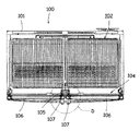
ここで、従来の低温ショーケース100の構造について図10乃至図12を参照して説明する。図10は従来の低温ショーケース100の扉を取り除いた状態の斜視図、図11は低温ショーケース100の平断面図、図12は図11の円D部分の拡大図を示している。
Here, the structure of the conventional low-
低温ショーケース100は、前面に開口する断熱箱体101により本体が構成されており、当該断熱箱体101内には、陳列室102が形成されている。そして、この断熱箱体101の下方には、機械室が形成されており、当該機械室前面は、前面パネル103により開閉自在に閉塞されている。
The main body of the low-
陳列室102の前面開口には、観音開き式のガラス扉106、106が設けられている。この扉106の周縁部裏面には、磁性体(磁石)107Mを備えたガスケット107が取り付けられている。そして、陳列室102の前面開口104の例えば中央部に上下に渡って柱状に形成された中支柱105が立設されている。そして、ガラス扉106のガスケット107内に設けられた磁石107Mによって、中支柱105の前面105Aとガラス扉106のそれぞれの開放側の側端部後面のガスケット107が密着することにより、陳列室102内が閉塞されている。
At the front opening of the
ここで、中支柱105は、図12に示すように、上下に延在して形成される後パネル108と、前パネル(金属製)109と、これらパネル108、109間を連結する樹脂製のブレーカ110、110により構成されており、これらパネル108、109及びブレーカ110、110にて囲繞される空間には、断熱材111が発泡充填されている。
Here, as shown in FIG. 12, the
しかしながら、陳列室102内が冷却されると、中支柱105自体もガラス扉106の枠も冷気に晒される。そのため、外気と接触する中支柱105の前面105Aやガラス扉106のガスケット107表面に結露が発生することとなる。係る結露が生じると、ガラス扉106の開閉時に中支柱105などに付着した結露水によって開閉する手指を濡らしてしまったり、開閉動作によって跳ねた結露水によって服などを濡らしてしまう不都合が生じる。更には、ガラス扉106に付着した結露による水滴が落下することにより、設置床面を濡らしてしまうなどの不都合が生じる。
However, when the inside of the
そこで、当該結露水の発生を防止するため、ガラス扉106の開放側の側端部後面が密着する前パネル109の後面に、電気ヒータ(コードヒータ)を当接した状態で交熱的に配設し、当該電気ヒータに通電を行うことによって、中支柱105の前パネル109を加熱し、ガラス扉106やガスケット107、更には、中支柱前面105Aへの結露の発生を抑制していた。
しかしながら、係る電気ヒータによる加熱は、常時通電を行うこととなるため、ショーケース自体の消費電力量が増加し、ランニングコストの高騰を招く問題があった。また、電気ヒータを中支柱105の断熱材111内に配設することから、作業工程中にヒータの断線などの不具合が発生した場合には、修理が不可能となる問題がある。
However, since heating by such an electric heater always energizes, there is a problem that the power consumption of the showcase itself increases and the running cost increases. In addition, since the electric heater is disposed in the
そこで、本発明は従来の技術的課題を解決するためになされたものであり、簡素な構成により、凝縮器等からの廃熱を利用することによって効果的に中支柱、特に、扉上部のガスケットへの結露を解消することができる低温ショーケースを提供することを目的とする。 Therefore, the present invention has been made to solve the conventional technical problems, and by using the waste heat from the condenser or the like with a simple configuration, the middle strut, in particular, the gasket at the upper part of the door can be effectively used. An object of the present invention is to provide a low-temperature showcase that can eliminate condensation on the surface.
本発明の低温ショーケースは、断熱壁から成る本体内に構成された陳列室と、この陳列室の前面開口縁に密着するガスケットを備えて当該前面開口を開閉自在に閉塞する扉と、陳列室の開口部に設けられ、前面に扉のガスケットが当接する中支柱と、陳列室下方の断熱壁外に構成された機械室と、この機械室内に配設された圧縮機、凝縮器、凝縮器用ファンなどから成る冷却ユニットとを備えたものであって、中支柱に上下に渡って取り付けられ、内部に中支柱ダクトを構成する中支柱ダクト部材と、凝縮器用ファンから吐出された空気を中支柱ダクト内に導入する導入部と、中支柱ダクト内を上昇した空気を、扉上部と本体間におけるガスケットの外側に向けて排出する排気孔とを備えたことを特徴とする。 The low-temperature showcase of the present invention includes a display chamber configured in a main body made of a heat insulating wall, a door that includes a gasket that is in close contact with the front opening edge of the display chamber, and that closes the front opening so as to be openable and closable. The middle strut, which is provided at the opening of the door, is in contact with the gasket of the door on the front surface, the machine room is constructed outside the heat insulating wall below the display room, and the compressor, condenser, and condenser disposed in the machine room. A cooling unit composed of a fan and the like, which is attached to the middle strut vertically and constitutes a middle strut duct inside, and the air discharged from the condenser fan is taken into the middle strut It is characterized by having an introduction part to be introduced into the duct and an exhaust hole for discharging the air rising in the middle strut duct toward the outside of the gasket between the upper part of the door and the main body.
請求項2の発明の低温ショーケースは、上記発明において、排気孔は、中支柱ダクト部材に複数設けられていると共に、各排気孔の開口面積は、上方のもの程大きくなるよう設定されていることを特徴とする。
In the low temperature showcase of the invention of
請求項3の発明の低温ショーケースは、上記各発明において、中支柱ダクト部材は、中支柱の前面に設けられていることを特徴とする。
The low temperature showcase of the invention of
本発明によれば、断熱壁から成る本体内に構成された陳列室と、この陳列室の前面開口縁に密着するガスケットを備えて当該前面開口を開閉自在に閉塞する扉と、陳列室の開口部に設けられ、前面に扉のガスケットが当接する中支柱と、陳列室下方の断熱壁外に構成された機械室と、この機械室内に配設された圧縮機、凝縮器、凝縮器用ファンなどから成る冷却ユニットとを備えた低温ショーケースにおいて、中支柱に上下に渡って取り付けられ、内部に中支柱ダクトを構成する中支柱ダクト部材と、凝縮器用ファンから吐出された空気を中支柱ダクト内に導入する導入部と、中支柱ダクト内を上昇した空気を、扉上部と本体間におけるガスケットの外側に向けて排出する排気孔とを備えたので、導入部より中支柱ダクト内に導入された機械室内からの暖気(廃熱)を、直接、扉上部と本体間におけるガスケットの外側に向けて排出することができる。これにより、当該扉上部と本体間におけるガスケットを暖気によって加熱することができ、扉上部に設けられるガスケットや当該ガスケット付近の中支柱表面に結露が発生し難くなる。 According to the present invention, a display chamber configured in a main body made of a heat insulating wall, a door provided with a gasket that is in close contact with a front opening edge of the display chamber, and that opens and closes the front opening, and an opening of the display chamber The middle strut that is provided at the front and the door gasket abuts on the front surface, the machine room configured outside the heat insulating wall below the display room, the compressor, the condenser, the condenser fan, and the like disposed in the machine room In a low-temperature showcase comprising a cooling unit comprising: a middle strut duct member that is mounted vertically on the middle strut and forms a middle strut duct inside, and the air discharged from the condenser fan inside the middle strut duct It was introduced into the middle strut duct from the introduction section because it was equipped with an introduction part to be introduced into and an exhaust hole for discharging the air rising in the middle strut duct toward the outside of the gasket between the upper part of the door and the main body. machine The warm air from the inner (exhaust heat) can be directly discharged toward the outside of the gasket between the door top and body. Thereby, the gasket between the said door upper part and a main body can be heated with warm air, and it becomes difficult to generate | occur | produce dew condensation on the gasket provided in a door upper part, or the middle support | pillar surface vicinity of the said gasket.
そのため、扉の開閉動作時に、扉上部に付着した水滴が使用者に飛び散る都合や、当該水滴によって床面を濡らしてしまうなどの不都合を抑制することが可能となる。また、係る部分における中支柱表面に結露水が付着し難くなることから、扉裏面との密着性の向上を図ることが可能となり、陳列室内の冷気の漏洩を抑制することが可能となる。 Therefore, when the door is opened and closed, it is possible to suppress inconveniences such as water droplets adhering to the upper part of the door scattering to the user and the floor surface being wetted by the water droplets. Moreover, since it becomes difficult for dew condensation water to adhere to the middle support | pillar surface in the part concerned, it becomes possible to aim at the adhesiveness with a door back surface, and it becomes possible to suppress the leakage of the cool air in a display room.
請求項2の発明によれば、上記発明において、排気孔は、中支柱ダクト部材に複数設けられていると共に、各排気孔の開口面積は、上方のもの程大きくなるよう設定されていることので、より機械室から離間し、暖気が届きがたい上方ほど、効率的に暖気の排出させることができ、効果的に扉上部に設けられるガスケットや、当該ガスケット付近の中支柱表面に結露が発生し難くなる。
According to the invention of
請求項3の発明によれば、上記各発明に加えて、中支柱ダクト部材は、中支柱の前面に設けられているので、中支柱ダクト内を上昇する凝縮器用ファンから吐出された暖気からの伝導熱によって、中支柱の前面に設けられる中支柱ダクト部材を加熱することができる。
According to the invention of
これにより、外気が接触する中支柱ダクト部材の上下に渡って、その表面に結露が発生し難くなる。そのため、中支柱ダクト部材の前面に当接する扉のガスケットにも結露が生じ難くなり、扉の開閉動作時に手指を濡らしてしまう不都合や扉裏面に付着した水滴によって床面を濡らしてしまうなどの不都合を抑制することが可能となる。また、中支柱表面に結露水が付着し難くなることから、中支柱前面と扉のガスケットとの密着性の向上を図ることが可能となり、陳列室内の冷気の漏洩を抑制することが可能となる。 This makes it difficult for condensation to occur on the surface of the middle strut duct member that is in contact with outside air. For this reason, condensation is less likely to occur on the door gasket that contacts the front surface of the middle strut duct member, resulting in inconvenience that the fingers get wet when the door is opened and closed, and the floor surface gets wet due to water droplets adhering to the back of the door. Can be suppressed. In addition, since it becomes difficult for condensed water to adhere to the surface of the middle column, it becomes possible to improve the adhesion between the front surface of the middle column and the gasket of the door, and it is possible to suppress the leakage of cold air in the display room. .
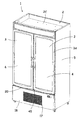
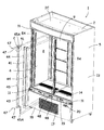
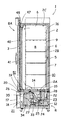
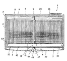
次に、図面を参照して本発明の実施形態について詳述する。図1は低温ショーケース1の斜視図、図2は図1の扉3を取り外した状態の低温ショーケース1の一部分解斜視図、図3は図1の縦断側面図、図4は低温ショーケース1の横断平面図、図5は図4の円Aの拡大図、図6は図5の円Bの拡大図、図7は図3の低温ショーケース1下部の拡大断面図、図8は図3の低温ショーケース1上部の拡大断面図、図9は図2の円Cの拡大図をそれぞれ示している。
Next, embodiments of the present invention will be described in detail with reference to the drawings. 1 is a perspective view of the
本実施例のショーケース1はスーパーマーケットやコンビニエンスストアなどの店舗に設置されて商品を冷却しながら陳列する低温ショーケースであり、前面に開口を有する断熱箱体(断熱壁)より本体2が構成されている。この本体2は前面に開口する鋼板製の外箱5と、この外箱5内に間隔を存して組み込まれた前面に開口する鋼板若しくは硬質合成樹脂製の内箱6と、外箱5及び内箱6間に発泡充填された発泡ポリウレタンから成る断熱材7とから構成されている。尚、本実施例では、当該本体2の前面開口上縁は、天壁2Cの前端が所定寸法だけ下方に延在して構成される。
The
そして、内箱6の内方には、前方に開口する陳列室8が形成され、当該前面開口(開口部)8Aは内部を透視可能とするガラス4を有する観音開き式の扉3、3によって開閉自在に閉塞される。各扉3は、ヒンジ部材11によって本体2の一側を中心に回動自在に枢支される。尚、扉3の詳細な構成については後述する。
A
本体2の底面には、所定の高さを有する台脚アングル12が取り付けられており、この台脚アングル12の両側面は、本体2の両側面と共に化粧パネル13にて被覆されている。これにより、本体2の下方には、断熱壁外において前方に開口を有する機械室21が形成される。そして、本体2の底壁2Aには、断熱材5を貫通するかたちで冷気吸込口14及び冷気吐出口15が前後にそれぞれ形成されている。
A
機械室21の天井となる本体2の底壁2A下面には、上面に開口を有する冷却箱22が当接して設けられる。この冷却箱22の内部には、冷却室23が形成され、冷却装置を構成する冷却器24及び当該冷却器24の前側には冷却器用ファン25が配設される。尚、この冷却箱22の上面開口には冷却箱22側の冷気吸込口27及び冷気吐出口28が形成されている。これら冷気吸込口27及び冷気吐出口28は、それぞれ本体2の底壁2Aに形成された前記冷気吸込口14及び冷気吐出口15にそれぞれ対応する。
A
他方、本体2の背壁2Bの内方には、底壁2Aに形成された冷気吐出口15と陳列室8の上部とを連通するダクト10を構成する仕切板9が取り付けられている。この仕切板9の上端には、冷却器用ファン25から吐出された冷気を供給するための冷気吐出口16が形成されていると共に、陳列室8背面を構成する仕切板9には、複数の開口9Aが形成されている。
On the other hand, a partition plate 9 constituting a
一方、前記機械室21内には、前記冷却器24と共に冷凍サイクルの冷媒回路を構成する圧縮機33、凝縮器34等と、それらに送風する凝縮器用ファン35から成る冷却ユニットRなどが設けられている。
On the other hand, in the
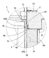
そして、機械室21の前面には、複数の吸込口17が穿設された機械室カバー18により開閉自在に閉塞されている。この機械室カバー18は、機械室21前面開口縁から前記扉3の下方にまで延在して形成されている。機械室カバー18の上面は、図7の部分拡大図に示すように、陳列室8の前面開口(開口部)8A下部に対応する位置に上方に開口する排気口(吹出部)19が左右(長手方向)に延在して複数、形成されていると共に、当該排気口19の前側には、当該排気口19の開口縁よりも低く形成される露受部24が形成されている。
The front surface of the
また、機械室21内に配設される凝縮器用ファン35は、当該凝縮器用ファン35の前側(即ち、空気吸込側に相当する機械室カバー18側)に位置する凝縮器34の上端に渡ってファンケース26が取り付けられている(図3参照)。このファンケース26の前端は、機械室カバー18の吸込口17の上方に位置する裏面にまで渡って構成されており、これによって、吸込口17から吸い込まれ、凝縮器34の廃熱によって加熱された空気の一部がファンケース26と本体2の底壁2Aとの間に形成される排気ダクト51を介して排気口19から上方に排気される構成とされる。尚、本実施例では、ファンケース26は、機械室カバー18裏面にまで渡って形成されているものとしているが、これに限定されるものではなく、排気ダクト51を構成することができるものであれば、二部品以上の仕切板などによって構成しても良いものとする。
The
次に、扉3の構成について説明する。扉3は、例えば硬質合成樹脂にて構成される扉枠3Aと、当該扉枠3Aに嵌め込まれた透明複層ガラス4と、扉枠3Aの内面(陳列室8側を構成する面)周囲に取り付けられたガスケット40とから構成される。扉3の下辺を構成する扉枠3Aには、上下方向に内部を貫通する複数の図示しない通風孔が形成されており、当該通風孔は、ガラス4の外方側(陳列室8側とは反対側)に開口している。また、ガスケット40内には、陳列室8の前面開口縁8Aに密着して閉塞するための磁性体としての磁石が設けられている。
Next, the configuration of the
そして、本実施例では、略同一寸法の観音開き式の扉3にて構成されているため、本体2の開口部8Aの略中央には、上下に渡って各扉3の中央側に位置するガスケット40が当接する中支柱41が立設されている。係る中支柱41は、図2の斜視図に示すように、上下に延在して形成される図示しない金属製の後パネルと、前パネル43と、これらパネル間を連結する樹脂製のブレーカ44、44により構成されており、これらパネル43、ブレーカ44にて囲繞される空間には、断熱材が発泡充填されている。金属製材料にて構成される前パネル43の前面は、両ブレーカ44の前端と略面一に構成されている。
In the present embodiment, since it is constituted by the
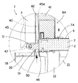
そして、この中支柱41の前面に対応する位置に、当該中支柱41前面との間に中支柱ダクト42を構成する中支柱ダクト部材45が取り付けられる。この中支柱ダクト部材45は、少なくとも前パネル43がガスケット40の磁石と磁力によって密着可能とする材料、例えば鋼板性材料にて構成されており、その上端は、図8に示すように、本体2の天壁2Cの前面であって、少なくとも扉3のガスケット40上辺40Aよりも上方、本実施例では、扉3の上縁よりも上方にまで延在して構成されている。また、その下端は、図7に示すように、本体2の底壁2Aの前面若しくは、前面より下方であって、前記機械室カバー18に形成される排気口19内にまで延在して構成されている。
Then, a middle
本実施例では、当該中支柱ダクト部材45の下端は、機械室カバー18の排気口19内にて開口する導入部50が形成されており、排気口19から排出される機械室21内の排気を当該導入部50を介して中支柱ダクト42内に流入可能な構成としている。
In the present embodiment, the lower end of the middle
そして、この中支柱ダクト部材45は、図6に示すように、両扉3のガスケット40を回避した位置に設けられ、その断面は、扉3を閉じた状態で、扉枠3Aの後面と、本体2の天壁2C前面、中支柱41前面、底壁2Aの前面との間の隙間寸法内に収容可能とする寸法で、後方(中支柱41側)に開口する略コ字状を呈し、その両側端は、外方に向けて折曲形成されたフランジ45A、45Aとされている。
And this middle support |
これらフランジ45A、45Aの裏面は、本体2の天壁2C前面、中支柱41前面及び底壁2Aの前面と当接可能とされており、天壁2C前面と当接する位置及び底壁2Aの前面と当接する位置には、ネジ止めにより固定するためのねじ穴46が形成されている。そのため、当該中支柱ダクト部材45の上端は、天壁2C前面に形成される図示しないねじ穴と当該ダクト部材45のねじ穴46とを重合してネジ47によって固定され、中支柱ダクト部材45の下端は、底壁2A前面に形成されるねじ穴48と、当該ダクト部材45のねじ穴46とを重合してネジ47によって固定される。
The rear surfaces of these
このとき、天壁2C前面、底壁2Aの前面と、中支柱41の前面とは、略面一とされているため、中支柱ダクト部材45のフランジ45Aと、中支柱41前面とは、当接して設けられることとなる。
At this time, since the front surface of the
そして、この中支柱ダクト部材45の上部両側面には、上下に複数の排気孔51・・・が設けられている。これら排気孔51は、図8及び図9に示すように、上側に形成される排気孔51の開口面積は、下側に形成されるものよりも大きくなるように形成されている。また、これらの排気孔51の一部は、図8に示すように扉3のガスケット40上辺40Aよりも上側に位置して形成されている。
A plurality of exhaust holes 51... Are provided on the upper side surfaces of the middle
尚、当該中支柱ダクト部材45の上端は、図9に示すように上方に開口して形成されていてもよいが、これに限定されるものではなく、上壁を設けて上端を閉塞してもよい。
The upper end of the middle
係る構成により、扉3が閉じられた状態では、中支柱ダクト部材45は、扉3のガスケット40を回避した状態で扉枠3A後面と中支柱41前面との間に形成される隙間内に位置するため、扉3の開閉の邪魔となることなく、当該ガスケット40が中支柱41の前面の中支柱ダクト部材45両側に当接可能とされ、該ガスケット40内部に設けられる磁石の磁力によって中支柱41の前パネル43に密着可能とされる。
With such a configuration, when the
以上の構成により、冷却ユニットRが運転されると、冷却室23内の冷却器24は、冷却作用を発揮する。このとき、冷却器用送風機25が運転されることにより、冷却器24で冷却された冷気は、冷気吐出口28、15を介して本体2内のダクト10内を上昇し、当該冷気の一部は、冷気吐出口16から陳列室8上部前方に向けて吐出される。図3にて実線矢印にて示すように、陳列室8内に吐出された冷気は、前面開口8A上部、即ち、扉3上部に向けて吐出され、降下して陳列室8内を循環した後、冷気吸込口14、27を介して冷却室23内に帰還する。これにより、陳列室8内は、所定の温度にまで冷却される。
With the above configuration, when the cooling unit R is operated, the cooler 24 in the cooling chamber 23 exhibits a cooling action. At this time, when the
このとき、当該冷気循環を行う低温ショーケース1では、陳列室8内に吐出されたばかりの低温の冷気は、図1の一点破線にて囲繞される扉3上部の扉枠3A付近が最も低温となる。そのため、係る部分において外気と接触する中支柱41の前面や扉3のガスケット40表面には、結露が発生しやすくなる。
At this time, in the low-
本実施例では、凝縮器用ファン35の運転によって機械室21前方の外気は、先ず、機械室カバー18の吸込口17を介してファンケース26にて囲繞された機械室21内に流入し、凝縮器34を空冷する。凝縮器34を空冷することによって温められた外気(暖気)の一部は、ファンケース26と本体2の底壁2Aにより形成される排気ダクト51内に流入し、機械室カバー18の上面に左右に渡って形成される排気口19より上方に吹き出される(図7では黒塗りの矢印で示す)。
In the present embodiment, the outside air in front of the
排気口19より上方に吹き出された暖気の一部は、周囲空気に拡散されることなく中支柱ダクト部材45に形成される導入部50より中支柱ダクト42内に流入し、該ダクト42内を上昇する。ダクト42内を上昇した暖気は、中支柱ダクト部材45の上部に形成される各排気孔51・・・より扉3上部と本体2(中支柱41)間におけるガスケット40の外側に向けて排出される。
Part of the warm air blown upward from the
本実施例では、排気孔51は、扉枠3Aの後面と、本体2の天壁2C前面、中支柱41前面、底壁2Aの前面との間の隙間内に収容される中支柱ダクト部材45の上部両側面に形成されているため、扉3の扉枠3Aの後面と、本体2との間から各扉3の上部のガスケット40、即ち、ガスケット40の上辺40Aや、中支柱41に当接するガスケット40の上部、更には、当該ガスケット40と上辺40Aにより構成される角隅部のそれぞれの外側に向けて暖気を直接、排出することができる。
In the present embodiment, the
特に、係る扉3上部の扉枠3A付近は、上述したように、陳列室8内に吐出されたばかりの低温の冷気が供給されることで、外気と接触する中支柱41の前面や扉3のガスケット40表面の内で最も低温となるため結露が生じやすいが、このように、扉3の扉枠3Aと本体2間におけるガスケット40上部を暖気の供給によって直接加熱することができるため、係る扉3上部に設けられるガスケット40や当該ガスケット40付近の中支柱41表面に結露が発生し難くなる。
In particular, in the vicinity of the
そのため、扉3の開閉動作時に、扉3上部に付着した水滴が使用者に飛び散る都合や、当該水滴によって床面を濡らしてしまうなどの不都合を抑制することが可能となる。また、係る部分における中支柱41表面に結露水が付着し難くなることから、扉3裏面(ガスケット40)との密着性の向上を図ることが可能となり、陳列室8内の冷気の漏洩を抑制することが可能となる。
Therefore, when the
また、本実施例では、中支柱ダクト部材45に形成される排気孔51は、上方のもの程、排気孔51の開口面積が大きくなるように設定されているので、より機械室21から離間し、暖気が届きがたい上方ほど、効率的に暖気の排出させることができる。従って、効果的に扉3上部に設けられるガスケット40や、当該ガスケット40付近の中支柱41表面に結露が発生し難くなる。
Further, in this embodiment, the
更に、本実施例では、中支柱ダクト部材45は、中支柱41の前面に設けられているので、中支柱ダクト42内を上昇する凝縮器用ファン35から吐出された暖気からの伝導熱によって、中支柱41の前面に設けられる中支柱ダクト部材45を加熱することができる。
Furthermore, in the present embodiment, the middle
これにより、外気が接触する中支柱ダクト部材45の上下に渡って、その表面に結露が発生し難くなる。そのため、中支柱ダクト部材45の前面に当接する扉3のガスケット40にも結露が生じ難くなり、扉3の開閉動作時に手指を濡らしてしまう不都合や扉裏面に付着した水滴によって床面を濡らしてしまうなどの不都合を抑制することが可能となる。また、中支柱41表面に結露水が付着し難くなることから、中支柱41前面と扉3のガスケット40との密着性の向上を図ることが可能となり、陳列室8内の冷気の漏洩を抑制することが可能となる。
This makes it difficult for dew condensation to occur on the surface of the middle
また、中支柱ダクト部材45の下端に設けられる導入部50は、前記機械室カバー18に形成される排気口19に対応して形成されているため、格別に機械室21からの暖気を誘導するための手段を設けることなく、効率的に、機械室21からの暖気を中支柱ダクト42内に導入することが可能となる。
Moreover, since the
尚、上記構成では、中支柱ダクト42は、既存のショーケースに設けられる中支柱の前面に中支柱ダクト部材45を取り付けることで、構成することが可能であるため、中支柱の設計変更を行うことなく、本発明を実現することが可能となる。
In the above configuration, the
1 低温ショーケース
2 本体(断熱箱体)
2A 底壁
2B 背壁
2C 天壁
3 扉
4 ガラス
8 陳列室
10 ダクト
16 冷気吐出口
17 吸込口
18 機械室カバー
19 排気口(吹出部)
20 露受部
21 機械室
24 冷却器
34 凝縮器
35 凝縮器用ファン
40 ガスケット
41 中支柱
42 中支柱ダクト
43 前パネル
44 ブレーカ
45 中支柱ダクト部材
50 導入部
1 Low-
DESCRIPTION OF
Claims (3)
前記中支柱に上下に渡って取り付けられ、内部に中支柱ダクトを構成する中支柱ダクト部材と、
前記凝縮器用ファンから吐出された空気を前記中支柱ダクト内に導入する導入部と、
前記中支柱ダクト内を上昇した空気を、前記扉上部と前記本体間における前記ガスケットの外側に向けて排出する排気孔とを備えたことを特徴とする低温ショーケース。 A display chamber configured in a main body made of a heat insulating wall, a door provided with a gasket that is in close contact with a front opening edge of the display chamber, and the front opening being closed so as to be openable and closable; It consists of a middle strut with which the gasket of the door abuts on the front surface, a machine room formed outside the heat insulating wall below the display room, a compressor, a condenser, a condenser fan and the like disposed in the machine room. In a low-temperature showcase with a cooling unit,
A middle strut duct member that is attached to the middle strut up and down and constitutes a middle strut duct inside,
An introduction part for introducing the air discharged from the condenser fan into the middle strut duct;
A low-temperature showcase comprising an exhaust hole for discharging the air rising in the middle strut duct toward the outside of the gasket between the upper portion of the door and the main body.
Priority Applications (4)
| Application Number | Priority Date | Filing Date | Title |
|---|---|---|---|
| JP2008212618A JP5372432B2 (en) | 2008-08-21 | 2008-08-21 | Low temperature showcase |
| CN2009101475045A CN101653330B (en) | 2008-08-21 | 2009-06-16 | Low temperature showcase |
| AU2009202747A AU2009202747B2 (en) | 2008-08-21 | 2009-07-06 | Low temperature showcase |
| US12/499,303 US8429923B2 (en) | 2008-08-21 | 2009-07-08 | Low temperature showcase |
Applications Claiming Priority (1)
| Application Number | Priority Date | Filing Date | Title |
|---|---|---|---|
| JP2008212618A JP5372432B2 (en) | 2008-08-21 | 2008-08-21 | Low temperature showcase |
Publications (2)
| Publication Number | Publication Date |
|---|---|
| JP2010048457A true JP2010048457A (en) | 2010-03-04 |
| JP5372432B2 JP5372432B2 (en) | 2013-12-18 |
Family
ID=41695058
Family Applications (1)
| Application Number | Title | Priority Date | Filing Date |
|---|---|---|---|
| JP2008212618A Active JP5372432B2 (en) | 2008-08-21 | 2008-08-21 | Low temperature showcase |
Country Status (4)
| Country | Link |
|---|---|
| US (1) | US8429923B2 (en) |
| JP (1) | JP5372432B2 (en) |
| CN (1) | CN101653330B (en) |
| AU (1) | AU2009202747B2 (en) |
Families Citing this family (28)
| Publication number | Priority date | Publication date | Assignee | Title |
|---|---|---|---|---|
| MX2010012533A (en) * | 2008-05-23 | 2010-12-20 | Electrolux Ab | Cold appliance. |
| JP2010057806A (en) * | 2008-09-05 | 2010-03-18 | Sanyo Electric Co Ltd | Low temperature showcase |
| EP2750556B1 (en) * | 2011-09-02 | 2016-04-06 | Carrier Corporation | Refrigerated sales furniture |
| US8695362B2 (en) | 2012-01-19 | 2014-04-15 | Hussmann Corporation | Refrigerated merchandiser with door having boundary layer |
| CN104768428B (en) * | 2012-09-24 | 2018-12-25 | 开利公司 | Freeze sale case |
| US8801116B1 (en) * | 2013-01-21 | 2014-08-12 | Anthony Inc. | Outside-mounted frame for refrigeration systems |
| CN108430277B (en) * | 2015-12-22 | 2021-04-02 | 开利公司 | Refrigerated merchandiser |
| DE102016203052A1 (en) * | 2016-02-26 | 2017-08-31 | BSH Hausgeräte GmbH | Domestic refrigerator with a door stop spar for two doors, which is connected to at least one connector with a boundary wall |
| US9750355B1 (en) * | 2016-03-02 | 2017-09-05 | Pepsico, Inc. | Refrigerated merchandise display system |
| KR101858237B1 (en) * | 2016-04-07 | 2018-05-16 | 주식회사 대우전자 | Refrigerator haing home bar and hot air unit for refrigerator |
| CN107062734B (en) * | 2016-12-27 | 2024-01-12 | 青岛海尔特种电冰柜有限公司 | Vertical refrigerator |
| CN107514855A (en) * | 2017-07-14 | 2017-12-26 | 青岛海尔电冰箱有限公司 | Refrigerating device |
| CN107246757B (en) * | 2017-07-31 | 2023-06-16 | 长虹美菱股份有限公司 | Refrigerator with anti-condensation structure and anti-condensation control method |
| TR201713310A2 (en) * | 2017-09-11 | 2019-03-21 | Bsh Ev Aletleri San Ve Tic As | A REFRIGERANT WITH AIR DIRECTIONAL ELEMENT |
| WO2019089588A1 (en) * | 2017-10-30 | 2019-05-09 | Littelfuse, Inc. | Door sensor for refrigeration appliances |
| CN111609656A (en) | 2019-02-25 | 2020-09-01 | Lg电子株式会社 | Entrance refrigerator and refrigerator |
| CN111609649B (en) | 2019-02-25 | 2022-01-18 | Lg电子株式会社 | Entrance refrigerator and refrigerator |
| CN111609648A (en) * | 2019-02-25 | 2020-09-01 | Lg电子株式会社 | Entrance refrigerator and refrigerator |
| US20220282903A1 (en) * | 2019-08-28 | 2022-09-08 | Qingdao Haier Refrigerator Co., Ltd. | Embedded refrigerator with switching assembly |
| JP2022546510A (en) * | 2019-08-28 | 2022-11-04 | チンダオ ハイアール レフリジレーター カンパニー リミテッド | built-in refrigerator |
| US20220282902A1 (en) * | 2019-08-28 | 2022-09-08 | Qingdao Haier Refrigerator Co., Ltd. | Free embedded refrigerator |
| AU2020336771B2 (en) * | 2019-08-28 | 2023-04-27 | Haier Smart Home Co., Ltd. | Free built-in refrigerator capable of increasing degree of opening |
| KR20210087152A (en) | 2020-01-02 | 2021-07-12 | 엘지전자 주식회사 | Entrance Refrigerator |
| KR20210087155A (en) | 2020-01-02 | 2021-07-12 | 엘지전자 주식회사 | Entrance Refrigerator |
| KR20210087158A (en) | 2020-01-02 | 2021-07-12 | 엘지전자 주식회사 | Storage system for an house entrance |
| KR20210087151A (en) * | 2020-01-02 | 2021-07-12 | 엘지전자 주식회사 | Entrance Refrigerator |
| KR20210087161A (en) | 2020-01-02 | 2021-07-12 | 엘지전자 주식회사 | Entrance Refrigerator |
| CN113693403B (en) * | 2021-08-24 | 2022-07-22 | 珠海格力电器股份有限公司 | Closed refrigeration display cabinet control method and device and closed refrigeration display cabinet |
Citations (2)
| Publication number | Priority date | Publication date | Assignee | Title |
|---|---|---|---|---|
| JP2000227271A (en) * | 1999-02-02 | 2000-08-15 | Hoshizaki Electric Co Ltd | Refrigerator |
| JP2002364974A (en) * | 2001-06-07 | 2002-12-18 | Sanyo Electric Co Ltd | Showcase |
Family Cites Families (7)
| Publication number | Priority date | Publication date | Assignee | Title |
|---|---|---|---|---|
| US1847109A (en) * | 1929-03-28 | 1932-03-01 | Frigidaire Corp | Refrigerating apparatus |
| US4009586A (en) * | 1975-02-03 | 1977-03-01 | Skvarenina John A | Method and apparatus for preventing condensation from forming about the periphery of a freezer door |
| JPH0510649A (en) * | 1991-06-28 | 1993-01-19 | Toshiba Corp | Show case |
| JP3675910B2 (en) | 1995-10-02 | 2005-07-27 | 三洋電機株式会社 | Cooling storage |
| US5816060A (en) * | 1996-12-23 | 1998-10-06 | General Electric Company | Air flow control in a side-by-side refrigerator |
| TR200704187T1 (en) * | 2004-12-22 | 2007-08-21 | Arçeli̇k Anoni̇m Şi̇rketi̇ | A cooler. |
| JP4971710B2 (en) * | 2006-07-21 | 2012-07-11 | 三洋電機株式会社 | Showcase |
-
2008
- 2008-08-21 JP JP2008212618A patent/JP5372432B2/en active Active
-
2009
- 2009-06-16 CN CN2009101475045A patent/CN101653330B/en active Active
- 2009-07-06 AU AU2009202747A patent/AU2009202747B2/en not_active Ceased
- 2009-07-08 US US12/499,303 patent/US8429923B2/en active Active
Patent Citations (2)
| Publication number | Priority date | Publication date | Assignee | Title |
|---|---|---|---|---|
| JP2000227271A (en) * | 1999-02-02 | 2000-08-15 | Hoshizaki Electric Co Ltd | Refrigerator |
| JP2002364974A (en) * | 2001-06-07 | 2002-12-18 | Sanyo Electric Co Ltd | Showcase |
Also Published As
| Publication number | Publication date |
|---|---|
| AU2009202747A1 (en) | 2011-01-20 |
| AU2009202747B2 (en) | 2015-10-22 |
| JP5372432B2 (en) | 2013-12-18 |
| US20100043472A1 (en) | 2010-02-25 |
| CN101653330A (en) | 2010-02-24 |
| CN101653330B (en) | 2011-11-23 |
| US8429923B2 (en) | 2013-04-30 |
Similar Documents
| Publication | Publication Date | Title |
|---|---|---|
| JP5372432B2 (en) | Low temperature showcase | |
| JP4971710B2 (en) | Showcase | |
| US8640476B2 (en) | Showcase with insulated wall separating the machine room from the cooling components | |
| WO2013021905A1 (en) | Cooking device | |
| AU2008203824B2 (en) | Showcase | |
| JP2010057807A (en) | Low temperature showcase | |
| JP2000105058A (en) | Refrigerator | |
| JPH09101075A (en) | Cooling storage apparatus | |
| JP2008002756A (en) | Microwave oven | |
| JP6887882B2 (en) | Cooling storage | |
| KR20030042713A (en) | Airguide-assembly for airconditioner | |
| JP4236263B2 (en) | Cold table refrigerator | |
| KR100903140B1 (en) | Air conditioner | |
| JP4475984B2 (en) | Open showcase | |
| KR20040014755A (en) | Air conditioner | |
| JP3389494B2 (en) | Refrigerated freezer showcase | |
| JP2877706B2 (en) | Cooling storage | |
| JPH10253223A (en) | Cooled storage chamber | |
| JP2003106746A (en) | Cooling unit | |
| JP2008267666A (en) | Showcase | |
| JP2004294031A (en) | Showcase | |
| KR20170100470A (en) | Refrigerator | |
| JPH06221744A (en) | Cold air circulating-type open showcase | |
| JP2002181438A (en) | Cooling storage device | |
| JP2003106736A (en) | Cooling unit |
Legal Events
| Date | Code | Title | Description |
|---|---|---|---|
| A621 | Written request for application examination |
Free format text: JAPANESE INTERMEDIATE CODE: A621 Effective date: 20110801 |
|
| A131 | Notification of reasons for refusal |
Free format text: JAPANESE INTERMEDIATE CODE: A131 Effective date: 20130129 |
|
| A521 | Request for written amendment filed |
Free format text: JAPANESE INTERMEDIATE CODE: A523 Effective date: 20130326 |
|
| TRDD | Decision of grant or rejection written | ||
| A01 | Written decision to grant a patent or to grant a registration (utility model) |
Free format text: JAPANESE INTERMEDIATE CODE: A01 Effective date: 20130820 |
|
| A61 | First payment of annual fees (during grant procedure) |
Free format text: JAPANESE INTERMEDIATE CODE: A61 Effective date: 20130918 |
|
| R151 | Written notification of patent or utility model registration |
Ref document number: 5372432 Country of ref document: JP Free format text: JAPANESE INTERMEDIATE CODE: R151 |