JP2010048081A - Electromechanical lock - Google Patents
Electromechanical lock Download PDFInfo
- Publication number
- JP2010048081A JP2010048081A JP2009190019A JP2009190019A JP2010048081A JP 2010048081 A JP2010048081 A JP 2010048081A JP 2009190019 A JP2009190019 A JP 2009190019A JP 2009190019 A JP2009190019 A JP 2009190019A JP 2010048081 A JP2010048081 A JP 2010048081A
- Authority
- JP
- Japan
- Prior art keywords
- electromechanical lock
- response
- communication device
- challenge
- operating
- Prior art date
- Legal status (The legal status is an assumption and is not a legal conclusion. Google has not performed a legal analysis and makes no representation as to the accuracy of the status listed.)
- Granted
Links
Images


Classifications
-
- G—PHYSICS
- G07—CHECKING-DEVICES
- G07C—TIME OR ATTENDANCE REGISTERS; REGISTERING OR INDICATING THE WORKING OF MACHINES; GENERATING RANDOM NUMBERS; VOTING OR LOTTERY APPARATUS; ARRANGEMENTS, SYSTEMS OR APPARATUS FOR CHECKING NOT PROVIDED FOR ELSEWHERE
- G07C9/00—Individual registration on entry or exit
- G07C9/00174—Electronically operated locks; Circuits therefor; Nonmechanical keys therefor, e.g. passive or active electrical keys or other data carriers without mechanical keys
- G07C9/00309—Electronically operated locks; Circuits therefor; Nonmechanical keys therefor, e.g. passive or active electrical keys or other data carriers without mechanical keys operated with bidirectional data transmission between data carrier and locks
-
- E—FIXED CONSTRUCTIONS
- E05—LOCKS; KEYS; WINDOW OR DOOR FITTINGS; SAFES
- E05B—LOCKS; ACCESSORIES THEREFOR; HANDCUFFS
- E05B47/00—Operating or controlling locks or other fastening devices by electric or magnetic means
- E05B47/02—Movement of the bolt by electromagnetic means; Adaptation of locks, latches, or parts thereof, for movement of the bolt by electromagnetic means
-
- G—PHYSICS
- G07—CHECKING-DEVICES
- G07C—TIME OR ATTENDANCE REGISTERS; REGISTERING OR INDICATING THE WORKING OF MACHINES; GENERATING RANDOM NUMBERS; VOTING OR LOTTERY APPARATUS; ARRANGEMENTS, SYSTEMS OR APPARATUS FOR CHECKING NOT PROVIDED FOR ELSEWHERE
- G07C9/00—Individual registration on entry or exit
- G07C9/00174—Electronically operated locks; Circuits therefor; Nonmechanical keys therefor, e.g. passive or active electrical keys or other data carriers without mechanical keys
- G07C9/00944—Details of construction or manufacture
-
- H—ELECTRICITY
- H04—ELECTRIC COMMUNICATION TECHNIQUE
- H04L—TRANSMISSION OF DIGITAL INFORMATION, e.g. TELEGRAPHIC COMMUNICATION
- H04L9/00—Cryptographic mechanisms or cryptographic arrangements for secret or secure communications; Network security protocols
- H04L9/32—Cryptographic mechanisms or cryptographic arrangements for secret or secure communications; Network security protocols including means for verifying the identity or authority of a user of the system or for message authentication, e.g. authorization, entity authentication, data integrity or data verification, non-repudiation, key authentication or verification of credentials
- H04L9/3271—Cryptographic mechanisms or cryptographic arrangements for secret or secure communications; Network security protocols including means for verifying the identity or authority of a user of the system or for message authentication, e.g. authorization, entity authentication, data integrity or data verification, non-repudiation, key authentication or verification of credentials using challenge-response
-
- H—ELECTRICITY
- H04—ELECTRIC COMMUNICATION TECHNIQUE
- H04W—WIRELESS COMMUNICATION NETWORKS
- H04W12/00—Security arrangements; Authentication; Protecting privacy or anonymity
- H04W12/08—Access security
- H04W12/084—Access security using delegated authorisation, e.g. open authorisation [OAuth] protocol
-
- E—FIXED CONSTRUCTIONS
- E05—LOCKS; KEYS; WINDOW OR DOOR FITTINGS; SAFES
- E05B—LOCKS; ACCESSORIES THEREFOR; HANDCUFFS
- E05B47/00—Operating or controlling locks or other fastening devices by electric or magnetic means
- E05B2047/0094—Mechanical aspects of remotely controlled locks
- E05B2047/0095—Mechanical aspects of locks controlled by telephone signals, e.g. by mobile phones
-
- H—ELECTRICITY
- H04—ELECTRIC COMMUNICATION TECHNIQUE
- H04L—TRANSMISSION OF DIGITAL INFORMATION, e.g. TELEGRAPHIC COMMUNICATION
- H04L2209/00—Additional information or applications relating to cryptographic mechanisms or cryptographic arrangements for secret or secure communication H04L9/00
- H04L2209/80—Wireless
- H04L2209/805—Lightweight hardware, e.g. radio-frequency identification [RFID] or sensor
-
- H—ELECTRICITY
- H04—ELECTRIC COMMUNICATION TECHNIQUE
- H04L—TRANSMISSION OF DIGITAL INFORMATION, e.g. TELEGRAPHIC COMMUNICATION
- H04L63/00—Network architectures or network communication protocols for network security
- H04L63/08—Network architectures or network communication protocols for network security for authentication of entities
- H04L63/0853—Network architectures or network communication protocols for network security for authentication of entities using an additional device, e.g. smartcard, SIM or a different communication terminal
-
- H—ELECTRICITY
- H04—ELECTRIC COMMUNICATION TECHNIQUE
- H04W—WIRELESS COMMUNICATION NETWORKS
- H04W4/00—Services specially adapted for wireless communication networks; Facilities therefor
- H04W4/80—Services using short range communication, e.g. near-field communication [NFC], radio-frequency identification [RFID] or low energy communication
-
- Y—GENERAL TAGGING OF NEW TECHNOLOGICAL DEVELOPMENTS; GENERAL TAGGING OF CROSS-SECTIONAL TECHNOLOGIES SPANNING OVER SEVERAL SECTIONS OF THE IPC; TECHNICAL SUBJECTS COVERED BY FORMER USPC CROSS-REFERENCE ART COLLECTIONS [XRACs] AND DIGESTS
- Y02—TECHNOLOGIES OR APPLICATIONS FOR MITIGATION OR ADAPTATION AGAINST CLIMATE CHANGE
- Y02D—CLIMATE CHANGE MITIGATION TECHNOLOGIES IN INFORMATION AND COMMUNICATION TECHNOLOGIES [ICT], I.E. INFORMATION AND COMMUNICATION TECHNOLOGIES AIMING AT THE REDUCTION OF THEIR OWN ENERGY USE
- Y02D30/00—Reducing energy consumption in communication networks
- Y02D30/70—Reducing energy consumption in communication networks in wireless communication networks
Abstract
Description
本発明は、電気機械式ロックに関する。 The present invention relates to an electromechanical lock.
種々のタイプの電気機械式ロックが、伝統的な機械式ロックの代わりをしつつある。電気機械式ロックは、外部電源、電気機械式ロック内のバッテリ、キー内のバッテリ、またはユーザが電気機械式ロックに電力を供給するための電気機械式ロック内の電力発生手段を必要とする。電気機械式ロックは、伝統的なロックに比べ多くの利点を有する。それらはより良いセキュリティを提供することや、キーまたはセキュリティ・トークンの制御がより容易なことである。 Various types of electromechanical locks are replacing traditional mechanical locks. The electromechanical lock requires an external power source, a battery in the electromechanical lock, a battery in the key, or a power generating means in the electromechanical lock for the user to power the electromechanical lock. Electromechanical locks have many advantages over traditional locks. They provide better security and are easier to control keys or security tokens.
さらに、大部分の電気機械式ロックおよび/またはキーおよびトークンは、プログラム可能である。電気機械式ロックは、種々のキーを受付けるが他のキーは受付けないようにプログラム可能である。 Furthermore, most electromechanical locks and / or keys and tokens are programmable. The electromechanical lock is programmable to accept various keys but not other keys.
全ての種類のロック・システムに関連する1つの問題は、キーまたはセキュリティ・トークンの配布である。キーおよびセキュリティ・トークンは、ユーザに配布されなければならない。また、ユーザが使うキーおよびセキュリティ・トークンをいくつか持つと、キーおよびトークンの取扱いは、煩雑になる。 One problem associated with all types of locking systems is the distribution of keys or security tokens. Keys and security tokens must be distributed to users. In addition, if there are several keys and security tokens used by the user, handling of the keys and tokens becomes complicated.
本発明の1つの態様によれば、チャレンジ(challenge)を記憶し、前記チャレンジを読取る通信装置用の無線インターフェイスを備え、前記通信装置から応答を受信し記憶し、前記応答を認証して、前記認証が成功した場合にオープン命令を発行するための電子回路であって、前記通信装置との通信用の動作電力を前記通信装置から無線で受取って、前記応答を記憶するように構成された前記電子回路と、前記オープン命令を受けて、前記電気機械式ロックを機械的オープン可能状態にセットするアクチュエータと、ユーザから入力を受けるように構成されたユーザ・インターフェイスと、前記認証用およびアクチュエータ動作用の動作電力を前記入力から発生するように構成された発電機と、を含む電気機械式ロックが提供される。 According to one aspect of the present invention, a challenge is stored, a wireless interface for a communication device that reads the challenge is provided, a response is received from the communication device, stored, the response is authenticated, An electronic circuit for issuing an open command when authentication is successful, configured to receive operating power for communication with the communication device wirelessly from the communication device and store the response An electronic circuit; an actuator that receives the open command and sets the electromechanical lock to a mechanically openable state; a user interface configured to receive input from a user; and for authentication and actuator operation And a generator configured to generate an operating power from the input, and an electromechanical lock is provided .
本発明の他の態様によれば、電子回路内にチャレンジを記憶するステップと;前記チャレンジを読取る前記通信装置用の無線インターフェイスを提供して、前記通信装置から応答を受信し記憶するための動作電力を通信装置から無線で受取るステップと;前記電気機械式ロックの前記ユーザ・インターフェイスによりユーザからの入力を受けて、前記応答を認証するための動作電力を前記入力から発生するステップと;前記認証が成功した場合にオープン命令を発行し、前記オープン命令に応答して前記電気機械式ロックを機械的オープン可能状態にセットするステップと、を含む電気機械式ロックを動作させる方法が提供される。 According to another aspect of the invention, storing a challenge in an electronic circuit; providing a wireless interface for the communication device that reads the challenge, and receiving and storing a response from the communication device Receiving power wirelessly from a communication device; receiving input from a user by the user interface of the electromechanical lock and generating operating power to authenticate the response from the input; Issuing an open command if successful, and setting the electromechanical lock to a mechanically openable state in response to the open command.
本発明のもう1つの態様によれば、電子回路内にチャレンジを記憶するステップと、通信装置からニア・フィールド(Near Field)通信クエリー(query)を受信するステップと、ニア・フィールド通信を使用して前記チャレンジを読取る通信装置用のインターフェイスを提供する無線インターフェイスを提供するステップと、ニア・フィールド通信を使用して前記通信装置から応答を受信するステップと、
前記応答を記憶し認証するステップと、前記認証が成功した場合にオープン命令を発行するステップと、を遂行するコンピュータ処理を実行するための命令のコンピュータ・プログラムをコード化したコンピュータ・プログラム製品が提供される。
According to another aspect of the invention, using a near field communication, storing a challenge in an electronic circuit, receiving a near field communication query from a communication device, and using near field communication. Providing a wireless interface that provides an interface for a communication device that reads the challenge, and receiving a response from the communication device using near field communication;
A computer program product that encodes a computer program of instructions for executing computer processing to perform the steps of storing and authenticating the response and issuing an open command when the authentication is successful is provided Is done.
本発明はいくつかの効果を有する。上記電子ロック・キー・システムおよび無線ソリューションは、無線ロックにおけるエネルギー消費を最小化した電源内蔵式ロック・ソリューションを可能にする。 The present invention has several effects. The electronic lock key system and wireless solution enables a self-powered locking solution that minimizes energy consumption in the wireless lock.
本発明のある実施例において、電子無線ロックを無線でオープンするのに電子無線キーが使用される。個人は、電子無線キーを個人の無線通信装置の一部として持つ。無線通信装置は、ニア・フィールド通信(NFC)装置を備えてよい。 In one embodiment of the invention, an electronic wireless key is used to open the electronic wireless lock wirelessly. Individuals have electronic wireless keys as part of their wireless communication device. The wireless communication device may comprise a near field communication (NFC) device.
本発明の実施例は、外部電源、電気機械式ロックやキー内のバッテリー、またはユーザにより電力が供給される電気機械式ロックに応用してよい。 Embodiments of the present invention may be applied to external power sources, electromechanical locks, batteries in keys, or electromechanical locks powered by a user.
以下に、単なる例示として、次の添付図面を参照して本発明の実施例を説明する。
下記の実施例は例示である。本明細書のいくつかの場所で、「ある」、「1つの」または「いくつかの」実施例への言及があっても、同一の実施例への言及であることや、その特徴が単一の実施例のみに適用されることを、必ずしも意味しない。種々の実施例の各特徴を組み合わせて他の実施例を構成してもよい。 The following examples are illustrative. In several places throughout this specification, references to “a”, “one”, or “several” embodiments are references to the same embodiment or are characterized simply. It does not necessarily mean that it applies only to one embodiment. Other embodiments may be configured by combining the features of the various embodiments.
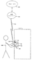
本発明のある実施例において、電子キーは、電気機械式無線ロックを無線でオープンするために使用される。個人は、このキーを個人の無線通信装置の一部として持つ。図1Aは電子ロック・システムの実施例を示す。ユーザ105は、ドア115を開けようとしている。ユーザは、通信装置106を持っている。
In one embodiment of the invention, the electronic key is used to open the electromechanical wireless lock wirelessly. Individuals have this key as part of their personal wireless communication device. FIG. 1A shows an embodiment of an electronic locking system. The
通信装置106は、ポータブル計算装置のことをいう。このような計算装置は、加入者識別モジュール(SIM)有りまたは無しで動作する無線移動通信装置を含み、携帯電話、スマートフォン、電子手帳(PDA)、ハンドセットのタイプの装置であるが、これらに限られない。通信装置106は、無線ネットワーク102への無線ネットワーク・チャネル104接続を有してよい。無線チャネル104接続および無線ネットワーク102は、GSM(Global System for Mobile Communications)、WCDMA(Wideband Code Divsion Access)、WLAN(Wireless Local Area Network)、その他の適当な標準/非標準無線通信手段により実施してよい。
The
ある実施例において、通信装置106は、加入者識別モジュール(Subscriber Identity Module)(SIM)または汎用集積回路カード(Universal Integrated Circuit Card)(UICC)を含む。SIMおよびUICCは、加入者を識別するために、移動通信システム内で使用される。特定のシステムの各通信装置は、そのようなIDを含む。SIMおよびUICCは、計算およびデータ・記憶が可能な集積回路を含む。
In certain embodiments, the
通信装置106は、短距離無線通信ユニットを備え、短距離無線通信ユニットは、他の各短距離無線ユニットを検出するとその短距離無線ユニットと通信するように構成されている。
The
ある実施例において、短距離無線通信は、ニア・フィールド通信(NFC)技法により実現される。NFCは、短距離の装置間のデータ交換用に設計された標準無線通信技法である。典型的な動作距離は、約0ないし20cmである。NFCは、特定の周波数(13.56MHz)を使用する。NFCトランシーバは、能動的、半受動的または受動的でよい。 In one embodiment, short range wireless communication is implemented by near field communication (NFC) techniques. NFC is a standard wireless communication technique designed for data exchange between short-range devices. A typical working distance is about 0 to 20 cm. NFC uses a specific frequency (13.56 MHz). The NFC transceiver may be active, semi-passive or passive.
能動トランシーバは、トランシーバのコンポーネント用および送信用の電力供給に使用する電源を含む。受動トランシーバは、電源を含まない。受動トランシーバは、近くのNFC送信により発生された磁界から動作電力を無線で受取る。こうして、受動トランシーバは、そのトランシーバのカバー・エリア内の能動トランシーバが送信した時のみ動作する。受動トランシーバは、アイドル状態にある時に電力を消費しない。典型的には、受動トランシーバは、メモリ回路およびNFC送信クエリーに応答するように構成された受動送信機を含むRFID(Radio−frequency identification)タグである。半受動トランシーバは、電源を含むが、この電源は、そのトランシーバのマイクロチップへの電力供給用であって信号送信用ではない。半受動装置は、送信に能動トランシーバからの電力供給を必要とする。 The active transceiver includes a power supply that is used to supply power for the transceiver components and for transmission. Passive transceivers do not include a power supply. Passive transceivers receive operating power wirelessly from magnetic fields generated by nearby NFC transmissions. Thus, a passive transceiver operates only when active transceivers within the transceiver's coverage area transmit. Passive transceivers do not consume power when in an idle state. Typically, the passive transceiver is a radio-frequency identification (RFID) tag that includes a memory circuit and a passive transmitter configured to respond to an NFC transmission query. A semi-passive transceiver includes a power supply, which is for powering the transceiver's microchip and not for signal transmission. Semi-passive devices require power from an active transceiver for transmission.
ドア115は、電気機械式ロック116を含む。電気機械式ロックは、ロック・インターフェイス108、ロック・アンテナ112およびロック・ボルト114を含む。ロック・アンテナ112は、電気機械式ロックの電子回路(図1Aに図示せず)に接続されている。電子回路は、短距離通信装置を含む。短距離通信装置は、NFCトランシーバでよい。ある実施例において、電気機械式ロックのNFCトランシーバは、受動トランシーバである。
The
ユーザが開けたいドアに近づいた時に、ユーザは、通信装置106をロック・アンテナ112へ近づける。電気機械式ロックの電子回路は、通信装置の短距離送信により電力が供給されて、処理が開始される。通信装置は、電気機械式ロックの電子回路から認証チャレンジを読取る。通信装置106は、応答を計算して、この応答を電気機械式ロックの電子回路に送信する。次にユーザは、電気機械式ロックのユーザ・インターフェイス108を動作させる。この動作は、ドア・ノブを回転することまたは電気機械式ロックに物理的キーを挿入することを含む。この動作は、電気機械式ロックを起動して、電気機械式ロックに動作電力を供給し認証させる。この認証において、電気機械式ロックは、応答を認証する。ある実施例において、応答は、認証チャレンジに対して認証される。認証が成功した場合に、電気機械式ロックは、オープン可能状態にセットされて、ユーザによるロック・ボルトの作動を可能にする。
When the user approaches the door he wants to open, the user brings the
上記の実施例において、物理的キーは、何も認証しないが、電気機械式ロックの動作電力を起動する。いくつかの実施例において、物理的キーは、何らかの追加的な認証を提供する。 In the above embodiment, the physical key does not authenticate anything but activates the operating power of the electromechanical lock. In some embodiments, the physical key provides some additional authentication.
ある実施例において、通信装置106は、無線ネットワーク・チャネル104を使用して、電気機械式ロックの電子回路から読取った認証チャレンジを、認証サービス100に送信する。認証サービス100は、応答を計算して、それを通信装置106に送信してよい。
In one embodiment, the
ある実施例において、認証サービスは、ロック・システムの電気機械式ロックに関するアクションのオーディット・トレール(audit trail)を記録してよい。こうして、電気機械式ロックをオープンしようとする各試みは、後で見ることができる。さらに、認証サービスは、時間限定アクセス権管理を用いてよい。ある実施例において、電気機械式ロックは、オーディット・トレール内に各アクションを記憶してよい。認証サービスは、1つ以上のコンピュータ、サーバまたは計算装置および関連のソフトウエアにより実現してよい。 In one embodiment, the authentication service may record an audit trail of actions related to the electromechanical lock of the locking system. Thus, each attempt to open the electromechanical lock can be seen later. Further, the authentication service may use time limited access right management. In certain embodiments, the electromechanical lock may store each action in an audit trail. The authentication service may be implemented by one or more computers, servers or computing devices and associated software.
本発明の実施例に関連して、いずれかの適当な認証技法を用いてよい。認証技法の選択は、電気機械式ロック116の望ましいセキュリティ・レベル、および恐らくは(特に、ユーザが電力供給する電気機械式ロックにおいて)認証のために許される電力消費によっても左右される。
Any suitable authentication technique may be used in connection with embodiments of the present invention. The choice of authentication technique also depends on the desired security level of the
ある実施例において、認証は、国家安全保障局(National Security Agency)(NSA)により設計されたSHA−1(Secure Hash Algorithm)機能により行われる。SHA−1において、(メッセージ・ダイジェストとして知られる)短縮デジタル表現は、(メッセージとして知られる)特定の入力データ・シーケンスから計算される。メッセージ・ダイジェストは、メッセージに対して高い確率でユニークである。SHA−1が「安全(Secure)」と呼ばれるのは、与えられたアルゴリズムに対して、特定のメッセージ・ダイジェストに対応する1つのメッセージを発見すること、または同一のメッセージ・ダイジェストを生成する2つの異なるメッセージを発見する計算が不可能だからである。メッセージのあらゆる変更は、非常に高い確率で異なるメッセージ・ダイジェストをもたらす。セキュリティの増加が必要ならば、より長いダイジェストを有し、まとめてSHA−2として知られているSHAファミリィ内の他のハッシュ機能(SHA−224、SHA−256、SHA−384およびSHA−512)を使用してよい。 In one embodiment, authentication is performed by a SHA-1 (Secure Hash Algorithm) function designed by the National Security Agency (NSA). In SHA-1, a shortened digital representation (known as a message digest) is computed from a specific input data sequence (known as a message). The message digest is unique with high probability for the message. SHA-1 is referred to as “Secure” because, for a given algorithm, two messages that either find one message corresponding to a particular message digest or generate the same message digest This is because it is impossible to calculate different messages. Every change in message results in a different message digest with a very high probability. If increased security is required, other hash functions within the SHA family (SHA-224, SHA-256, SHA-384 and SHA-512) have a longer digest and are collectively known as SHA-2. May be used.
ある実施例において、認証チャレンジは、ロック・システムid、ロックid、アクセス・データおよびチェック値を含む。ロック・システムidは、その電気機械式ロックが所属するロック・システムを識別する。ロックidは、ロック・システム内の電気機械式ロックを識別する。ロック・システム内の各電気機械式ロックは、ユニークなIDを含む。アクセス・データは、ランダムな数値データでよい。チェック値は、認証チャレンジの整合性を確認するサイクリック冗長チェック値である。 In one embodiment, the authentication challenge includes a lock system id, a lock id, access data, and a check value. The lock system id identifies the lock system to which the electromechanical lock belongs. The lock id identifies the electromechanical lock within the lock system. Each electromechanical lock in the lock system includes a unique ID. The access data may be random numerical data. The check value is a cyclic redundancy check value for confirming the consistency of the authentication challenge.
ある実施例において、認証サービス、または応答を計算する通信装置は、応答に基づいて認証が成功したか否かを決定してよい。通信装置106は、認証が成功したか否かをユーザに通知してよい。
In certain embodiments, an authentication service or a communication device that computes a response may determine whether authentication is successful based on the response. The
ある実施例において、通信装置のユーザの個人識別番号(PIN)または指紋データは、認証チャレンジに対する応答を生成する時に使用してよい。通信装置は、指紋を読取って、指紋に基づいて数値表現を生成するように構成された指紋データ・リーダを含んでよい。 In some embodiments, the personal identification number (PIN) or fingerprint data of the user of the communication device may be used when generating a response to the authentication challenge. The communication device may include a fingerprint data reader configured to read the fingerprint and generate a numerical representation based on the fingerprint.
認証チャレンジは、PINまたは指紋クエリーを含んでよい。通信装置のユーザは、PINをタイプ入力するか、通信装置の指紋データ・リーダを使用してよい。通信装置は、認証チャレンジに対する応答としてPINまたは指紋の数字表現を送信するように構成されている。電気機械式ロックは、電気機械式ロックをオープンできるようにするPINおよび指紋のセットを記憶するように構成されてよい。電気機械式ロックの電子回路が、応答と記憶された値とを比較して、一致した場合に、認証が成功したとみなされる。 The authentication challenge may include a PIN or fingerprint query. The communication device user may type in a PIN or use the communication device's fingerprint data reader. The communication device is configured to send a PIN or a numeric representation of a fingerprint as a response to the authentication challenge. The electromechanical lock may be configured to store a set of PINs and fingerprints that allow the electromechanical lock to be opened. Authentication is considered successful if the electromechanical lock electronic circuit compares the response with the stored value and matches.
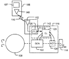
図1Bは、電気機械式ロック116および通信装置106のより詳細な例を示す。通信装置は、短距離通信ユニット140を含む。ある実施例において、短距離通信ユニット140は、能動タイプのNFCトランシーバである。通信装置106は、GSMネットワーク、WCDMAネットワークまたはWLANネットワークその他の適当な標準/非標準無線ネットワーク等の無線ネットワークへの無線ネットワーク・チャネル接続を実現するための無線トランシーバ107を含んでよい。
FIG. 1B shows a more detailed example of
電気機械式ロック116は、電子回路142を含む。電気機械式ロックは、さらに、ユーザ・インターフェイス108、および電気機械式ロックのユーザ・インターフェイスが作動する時に電気機械式ロック116に電力を供給するように構成されている発電機122を含む。
電子回路142は、特定用途集積回路ASIC等の1つ以上の集積回路として実施されてよい。個別論理コンポーネントから構成された回路、またはメモリ・ユニットおよび1つ以上のソフトウエア内蔵プロセッサ等の他の実施例も可能である。これら種々の実施例のハイブリッドも可能である。実施方法の選択に際して、当業者は、例えば、装置の電力消費、製造コスト、製造量について定められた要求を考慮する。電子回路142は、コンピュータ処理を実行するためのコンピュータ・プログラム命令を実行するように構成されてよい。
The
図1Bの実施例において、電子回路142は、2つの回路により実現されている。電子回路は、通信ユニット126およびロック電子回路120を含み、これらは、通信チャネル118により互いに接続されている。ある実施例において、ロック電子回路120は、マイクロコントローラおよびメモリ・ユニットにより実現されている。
In the embodiment of FIG. 1B, the
電気機械式ロックは、さらに、通信ユニット126に接続されたアンテナ112を含む。ある実施例において、通信ユニット126は、受動タイプのNFCトランシーバである。
The electromechanical lock further includes an
電気機械式ロックは、さらに、ロック・ボルト114を制御するアクチュエータ124を含む。認証成功後に、アクチュエータ124は、機械的オープン可能状態に電気機械式ロックをセットするように構成されている。アクチュエータは、発電機122により発生された電力を供給されてよい。アクチュエータ124は、機械的にロック状態にセットされてよいが、その詳細な説明は、本実施例の説明に不要である。
The electromechanical lock further includes an
アクチュエータ124が電気機械式ロックを機械的オープン可能状態にセットした時に、ロック・ボルト機構114は、例えば、ユーザ・インターフェイス108を作動することにより動かすことができる。他の適当な作動機構を使用してもよい。
When the
図2は、通信ユニット126の実施例を示す。通信ユニットは、アンテナ112と2つのメモリ・ユニット202、204と間の通信インターフェイス200からなる。メモリ・ユニット202、204付き通信インターフェイス200は、受動タイプのNFCトランシーバでよい。アンテナ112が能動NFC装置(例えば、図1Aおよび図1Bの通信装置106)の動作範囲内にある時に、通信ユニット126は、能動NFC装置により発生される磁界によりアンテナ112を介して電力を供給される。メモリ・ユニット202は、認証チャレンジを記憶するように構成され、メモリ・ユニット204は、認証応答を記憶するように構成される。能動NFC装置は、メモリ202、204付き通信インターフェイス200に電力を供給し、メモリ・ユニット202から無線でチャレンジを読取り、メモリ・ユニット204内に無線で応答を記憶する。
FIG. 2 shows an embodiment of the
電気機械式ロックのユーザ・インターフェイスが作動された時に、通信装置126は、通信チャネル118を使用するインターフェイス206を介して図1Bの発電機122により電力を供給される。ロック電子回路120は、メモリ204からの応答を読取ってメモリ・ユニット202に新しいチャレンジを書込む。
When the electromechanical lock user interface is activated, the
メモリ・ユニット202は、例えば、フラッシュまたはEEPROM技術により実現されるパーマネント(permanent)・メモリであり、メモリ・ユニット204は、例えば、RAMまたはDRAM技術により実現されるノンパーマネント(non−permanent)・メモリでよい。通信ユニット126は、所定の時間のみメモリ・ユニット204内に応答を記憶するように構成される;さもなければ応答書込み後に電気機械式ロックが動作しないと、セキュリティ・リスクが発生する。通信インターフェイス206は、メモリ・ユニット202、204とロック電子回路120との間の通信インターフェイスの一例を示す。メモリ・ユニット204の読取り動作およびメモリ・ユニット202への書込み動作時に、電気機械式ロックにより電力が供給される。
The
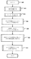
図3Aから図3Cまでは、本発明の実施例を示すフローチャートである。ここでは、ドア115の電気機械式ロック116は、デフォルトでロック状態にあり、オープン可能状態にセットされるまでロック状態のままであるとする。
3A to 3C are flowcharts showing an embodiment of the present invention. Here, it is assumed that the
図3Aと図3Bは、通信装置106の観点から実施例を示す。
3A and 3B show an embodiment from the perspective of the
オープン・シーケンスのスタートは、ステップ300である。
The start of the open sequence is
ステップ302で、通信装置106のユーザは、通信装置を起動する。これは、通信装置のNFCトランシーバのスイッチ・オンを含んでよい。通信装置は、ロック・アンテナが通信装置のNFCトランシーバのカバー・エリア内にあるように配置される。例えば、ユーザは、通信装置によりロック・アンテナに触れることができる。
In
ステップ304で、通信装置106は、NFCクエリーを電気機械式ロックに送信する。
In
ステップ306で、通信装置は、電気機械式ロックにより送信された現在のチャレンジを受信する。
In
図3Aのステップ308で、通信装置106は、応答を計算する。ある実施例において、応答は、通信装置106の処理ユニットにより計算される。ある実施例において、この応答は、通信装置106内に配置された加入者識別モジュール(SIM)または汎用集積回路カード(UICC)により計算される。
In step 308 of FIG. 3A, the
図3Bは、ステップ320で、通信装置106が認証サービス100にチャレンジを送信するもう1つの実施例を示す。
FIG. 3B shows another example where the
図3Bのステップ322で、認証サービス100は、チャレンジへの応答を計算して、それを通信装置106に送信する。この実施例では、時間限定アクセス権管理およびオーディット・トレイルの認証サービス100への記録が可能である。その後、下記の処理が図3Aと同様に続く。
In
ステップ310で、通信装置106は、電気機械式ロック116の通信ユニットに応答を送信する。
In
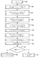
図3Cは、電気機械式ロック116の観点から実施例を示す。
FIG. 3C shows an embodiment in terms of
オープン・シーケンスのスタートは、ステップ330である。
The start of the open sequence is
ステップ332で、通信ユニット126は、通信装置106の送信により電力を供給され、通信装置からクエリーを受信する。
In
ステップ334において、現在のチャレンジは、メモリ202から読取られ、アンテナ112を使用して、インターフェイス200から通信装置へ送信される。
In
ステップ336で、通信ユニットのインターフェイス200は、通信装置106から応答を受信する。インターフェイスは、メモリ204内に応答を記憶する。メモリ204は、所定の期間、応答を記憶するように構成されている。
In
通信ユニット126の上記の動作用電力は、通信装置のNFC送信により供給される。
The power for operation of the
ステップ338で、電気機械式ロックは、電気機械式ロックのユーザ・インターフェイスからユーザ入力を受ける。ユーザ入力は、残りのオープン・シーケンス動作用の電力を起動する。
At
ステップ340で、ロック電子回路120は、現在のチャレンジを、記憶されている内部メモリから読取る。
At
ステップ342で、ロック電子回路120は、新しいチャレンジを計算して、それをその内部メモリ内に記憶し、チャネル118およびインターフェイス206を介してメモリ202内に記憶する。
At
ステップ344で、ロック電子回路120は、チャネル118およびインターフェイス206を介してメモリ204から応答を読取る。
At
ステップ346で、ロック電子回路120は、応答を認証する。ある実施例において、ロック電子回路120は、チャレンジに対する応答を認証する。
At
ステップ348で、認証が成功したかどうかがチェックされる。
In
認証が成功した場合には、ステップ350で、ロック電子回路120は、電気機械式ロックのアクチュエータ124にオープン命令を送る。アクチュエータ124は、電気機械式ロックをオープン可能状態にセットする。
If the authentication is successful, at
認証が失敗した場合には、ステップ352で、ロック電子回路120は、電気機械式ロックのアクチュエータ124にオープン命令を送らず、電気機械式ロックはロック状態のままである。
If the authentication fails, at
上記のように、ステップ338は、ユーザからの入力に基づく電気機械式ロックのための電力の起動を含む。ユーザ・インターフェイスにおける入力動作は、ドア・ノブを回転することまたは電気機械式ロックに物理的キーを挿入することを含んでよい。この動作は、電気機械式ロックを起動して、認証用動作電力を電気機械式ロックに供給する。
As described above,
図1Bのロック構造を用いた実施例において、電気機械式ロックのユーザ・インターフェイス108の作動は、発電機から電気機械式ロック116への電力供給を可能にする。発電機は、ドア・ノブの回転またはキーの挿入から電気を発生してよい。
In the embodiment using the locking structure of FIG. 1B, actuation of the electromechanical
図4A、図4Bおよび図4Cは、電子ロック・システムの他の実施例を示す。 4A, 4B and 4C show another embodiment of an electronic locking system.
図4Aの実施例において、ロック・アンテナ112は、ドア・ノブ108に埋め込まれている。この実施例において、ドア・オープン・シーケンスは、次のステップを含んでよい。最初に、ユーザは、通信装置106によりドア・ノブ108に触れる。第2段階で、ユーザ105は、ドア・ノブ108を回転し認証用の電力を起動して、電気機械式ロック116をオープン可能状態にセットする。第3段階で、ドア・ノブ108を回転してロック・ボルト114を作動させる。さらに、ロック・ボルト構造の代わりに、レバー・タイプの作動インターフェイスを使用できる。ユーザは、第2段階と第3段階をドア・ノブの1つの連続的な回転として経験する。
In the embodiment of FIG. 4A, the
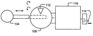
図4Bの例において、ロック・アンテナ112は、ドアに配置され、キー134は、電気機械式ロック116を動作させるために使用される。電気機械式ロックのユーザ・インターフェイスは、キーホール(keyhole)144を含む。この実施例において、ドア・オープン・シーケンスは、次のステップを含んでよい。最初に、ユーザは、通信装置106によりアンテナに触れる。第2段階で、キー134を電気機械式ロック116のキーホール114に挿入し認証用電力を起動して、電気機械式ロック116をオープン可能状態にセットする。第3段階において、キー134を回転してロック・ボルト114を作動させる。
In the example of FIG. 4B, the
図4Cの実施例は、図4Aおよび図4Bのロック構造を組合せた電気機械式ロック116を示す。図4Cの電気機械式ロックは、種々の動作モードを有してよい。ある実施例において、電気機械式ロック116は、キー134と、通信装置106から受信した応答との両方を認証する。電気機械式ロックは、両方の認証が成功した場合に、オープン可能状態にセットされる。
The embodiment of FIG. 4C shows an
もう1つの実施例において、電気機械式ロック116は、通信装置106から受信した応答を認証する。キー134は、ロック機構を作動させるためだけに使用される。
In another embodiment,
もう1つの実施例において、ロック動作は、異なるユーザに対して異なってよい。あるユーザは、認証のためにキー134を使用する。あるユーザ(例えば、一時的なユーザ)は、認証のために通信装置106を使用し、ドア・ノブ108を回転することにより電気機械式ロックをオープンする。
In another embodiment, the locking action may be different for different users. Some users use the key 134 for authentication. One user (eg, a temporary user) uses the
ある実施例において、本発明の機能は、ソフトウエアとして実現される。実施例は、電気機械式ロックを動作させるために上記ステップを遂行するコンピュータ処理を実行するための命令のコンピュータ・プログラムをコード化したコンピュータ・プログラム製品として実現してよい。 In one embodiment, the functions of the present invention are implemented as software. Embodiments may be implemented as a computer program product that encodes a computer program of instructions for performing computer processing to perform the above steps to operate an electromechanical lock.
技術の進歩によって、本発明の概念は、種々の方法により実施可能になることが当業者にとって明らかである。本発明およびその実施例は、上記実施例に限られず、各請求項の範囲内で変形してもよい。 It will be apparent to those skilled in the art that with the advancement of technology, the inventive concept can be implemented in various ways. The present invention and its embodiments are not limited to the above embodiments, and may be modified within the scope of the claims.
100 認証サービス
102 無線ネットワーク
104 無線ネットワーク・チャネル
105 ユーザ
106 通信装置
107 無線トランシーバ
108 ユーザ・インターフェイス
112 ロック・アンテナ
114 ロック・ボルト
115 ドア
116 電気機械式ロック
118 通信チャネル
120 ロック電子回路
122 発電機
124 アクチュエータ
126 通信ユニット
134 キー
140 短距離通信ユニット
142 電子回路
144 キーホール
200 無線インターフェイス
202,204 メモリ・ユニット
206 通信インターフェイス
DESCRIPTION OF
Claims (22)
前記オープン命令を受けて、前記電気機械式ロックを機械的オープン可能状態にセットするアクチュエータと、
ユーザから入力を受けるように構成されたユーザ・インターフェイスと、
前記認証用およびアクチュエータ動作用の動作電力を前記入力から発生するように構成された発電機と、
を含む電気機械式ロック。 A wireless interface for a communication device that stores a challenge and reads the challenge, receives and stores a response from the communication device, authenticates the response, and issues an open command if the authentication is successful An electronic circuit configured to wirelessly receive operating power for communication with the communication device from the communication device and store the response; and
An actuator that receives the open command and sets the electromechanical lock in a mechanically openable state;
A user interface configured to receive input from the user;
A generator configured to generate operating power for the authentication and actuator operation from the input;
Including electromechanical lock.
前記インターフェイス用の前記動作電力を得て、前記通信装置により発生されたニア・フィールド通信フィールドから前記応答動作を受信し記憶するように構成されている前記電気機械式ロック。 In the electromechanical lock according to any of the preceding items,
The electromechanical lock configured to obtain the operating power for the interface and to receive and store the response action from a near field communication field generated by the communication device.
所定時間、前記電子回路内に前記応答を記憶するように構成されている前記電気機械式ロック。 In the electromechanical lock according to any one of the preceding claims,
The electromechanical lock configured to store the response in the electronic circuit for a predetermined time.
前記ユーザ・インターフェイスによりユーザ入力を受けた後に、前記回路内で新しいチャレンジを計算してそのチャレンジを記憶するように構成されている前記電気機械式ロック。 In the electromechanical lock according to any one of the preceding claims,
The electromechanical lock configured to calculate a new challenge in the circuit and store the challenge after receiving user input by the user interface.
前記電子回路が、前記応答の生成時に、前記通信装置内で使用されたのと同一のアルゴリズムを使用することにより前記応答の前記認証を行うように構成されている前記電気機械式ロック。 In the electromechanical lock according to any one of the preceding claims,
The electromechanical lock, wherein the electronic circuit is configured to perform the authentication of the response by using the same algorithm used in the communication device when generating the response.
前記チャレンジが、ロック・システムid、ロックid、アクセス・データおよびチェック値を含む前記電気機械式ロック。 In the electromechanical lock according to any one of the preceding claims,
The electromechanical lock wherein the challenge includes a lock system id, a lock id, access data and a check value.
前記電子回路が、前記チャレンジに対する前記応答を認証するように構成されている前記電気機械式ロック。 In the electromechanical lock according to any one of the preceding claims,
The electromechanical lock, wherein the electronic circuit is configured to authenticate the response to the challenge.
前記電子回路が、
チャレンジを記憶し、通信装置用の無線周波数インターフェイスを提供して、前記通信装置からの応答を受信し記憶するための通信ユニットと、
前記通信ユニットからの前記応答およびメモリからの前記チャレンジを読取り前記応答を認証してオープン命令を発行するためのロック電子回路と、
を含む前記電気機械式ロック。 In the electromechanical lock according to any one of the preceding claims,
The electronic circuit is
A communication unit for storing a challenge, providing a radio frequency interface for the communication device, and receiving and storing a response from the communication device;
Lock electronics for reading the response from the communication unit and the challenge from memory to authenticate the response and issue an open command;
Including said electromechanical lock.
前記通信ユニットが、前記ロック電子回路と通信するように構成されたインターフェイスを含む前記電気機械式ロック。 The electromechanical lock according to claim 8,
The electromechanical lock, wherein the communication unit includes an interface configured to communicate with the lock electronics.
前記通信ユニットは、
前記チャレンジを記憶するためのメモリと、
前記応答を記憶するためのメモリと、
前記無線周波数インターフェイスに接続されたアンテナと、
を含む前記電気機械式ロック。 The electromechanical lock according to claim 8,
The communication unit is
A memory for storing the challenge;
A memory for storing the response;
An antenna connected to the radio frequency interface;
Including said electromechanical lock.
前記電気機械式ロックに挿入されたキーを認証して、前記認証が成功した場合にオープン命令を発行するように構成されている前記電気機械式ロック。 In the electromechanical lock according to any one of the preceding claims,
The electromechanical lock configured to authenticate a key inserted into the electromechanical lock and to issue an open command if the authentication is successful.
前記ロック・ユーザ・インターフェイスが、ドア・ノブを含み、前記ドア・ノブがユーザにより作動された時に、前記認証用およびアクチュエータ動作用の動作電力を発生するように構成されている前記電気機械式ロック。 In the electromechanical lock according to any one of the preceding claims,
The electromechanical lock wherein the lock user interface includes a door knob and is configured to generate operating power for the authentication and actuator operation when the door knob is actuated by a user .
前記ロック・ユーザ・インターフェイスがキーホールを含み、前記キーホールにキーが挿入された時に、前記認証用およびアクチュエータ動作用の動作電力を発生するように構成されている前記電気機械式ロック。 In the electromechanical lock according to any one of the preceding claims,
The electromechanical lock, wherein the lock user interface includes a keyhole and is configured to generate operating power for the authentication and actuator operation when a key is inserted into the keyhole.
前記チャレンジを読取る前記通信装置用の無線インターフェイスを提供して、前記通信装置から応答を受信し記憶するための動作電力を通信装置から無線で受取るステップと;
前記電気機械式ロックの前記ユーザ・インターフェイスによりユーザからの入力を受けて、前記応答を認証するための動作電力を前記入力から発生するステップと;
前記認証が成功した場合にオープン命令を発行し、前記オープン命令に応答して前記電気機械式ロックを機械的オープン可能状態にセットするステップと、
を含む電気機械式ロックを動作させる方法。 Storing the challenge in the electronic circuit;
Providing a wireless interface for the communication device to read the challenge and wirelessly receiving operating power from the communication device for receiving and storing a response from the communication device;
Receiving input from a user through the user interface of the electromechanical lock and generating operating power from the input to authenticate the response;
Issuing an open command if the authentication is successful, and setting the electromechanical lock to a mechanically openable state in response to the open command;
A method of operating an electromechanical lock comprising:
ニア・フィールド通信を使用して前記通信装置と通信するステップを含む前記電気機械式ロックを動作させる方法。 A method of operating an electromechanical lock according to claim 14, further comprising:
A method of operating the electromechanical lock comprising communicating with the communication device using near field communication.
前記通信装置により発生されたニア・フィールド通信フィールドにより前記応答の前記受信用および記憶用の電力を供給するステップを含む前記電気機械式ロックを動作させる方法。 A method of operating an electromechanical lock according to any of the preceding claims, further comprising:
A method of operating the electromechanical lock comprising supplying the receiving and storing power of the response by a near field communication field generated by the communication device.
所定時間、前記電子回路内に前記応答を記憶するステップを含む前記電気機械式ロックを動作させる方法。 A method of operating an electromechanical lock according to any of the preceding claims, further comprising:
A method of operating the electromechanical lock comprising storing the response in the electronic circuit for a predetermined time.
前記チャレンジに対する前記応答を認証するステップを含む前記電気機械式ロックを動作させる方法。 A method of operating an electromechanical lock according to any of the preceding claims, further comprising:
A method of operating the electromechanical lock comprising authenticating the response to the challenge.
前記ユーザ・インターフェイスによりユーザ入力を受けた後に、新しいチャレンジを計算し記憶するステップを含む前記電気機械式ロックを動作させる方法。 A method of operating an electromechanical lock according to any of the preceding claims, further comprising:
A method of operating the electromechanical lock comprising calculating and storing a new challenge after receiving user input by the user interface.
前記通信装置内で前記応答を計算するステップを含む前記電気機械式ロックを動作させる方法。 A method of operating an electromechanical lock according to any of the preceding claims, further comprising:
A method of operating the electromechanical lock comprising calculating the response in the communication device.
前記通信装置が認証サービスに前記チャレンジを送信するステップと、
前記認証サービスが前記応答を計算するステップと、
前記通信装置が前記認証サービスから前記応答を受信するステップと、
前記通信装置が前記電子回路に前記応答を送信するステップと、
を含む前記電気機械式ロックを動作させる方法。 A method for operating an electromechanical lock according to any of claims 14 to 19, further comprising the communication device sending the challenge to an authentication service;
The authentication service calculating the response;
The communication device receiving the response from the authentication service;
The communication device transmitting the response to the electronic circuit;
A method of operating the electromechanical lock comprising:
通信装置からニア・フィールド通信クエリーを受信するステップと、
ニア・フィールド通信を使用して前記チャレンジを読取る通信装置用のインターフェイスを提供する無線インターフェイスを提供するステップと、
ニア・フィールド通信を使用して前記通信装置から応答を受信するステップと、
前記応答を記憶し認証するステップと、
前記認証が成功した場合にオープン命令を発行するステップと、
を遂行するコンピュータ処理を実行するための命令のコンピュータ・プログラムをコード化したコンピュータ・プログラム製品。
Storing the challenge in the electronic circuit;
Receiving a near field communication query from a communication device;
Providing a wireless interface providing an interface for a communication device that reads the challenge using near field communication;
Receiving a response from the communication device using near field communication;
Storing and authenticating the response;
Issuing an open command if the authentication is successful;
A computer program product in which a computer program of instructions for executing a computer process for performing the above is coded.
Applications Claiming Priority (2)
| Application Number | Priority Date | Filing Date | Title |
|---|---|---|---|
| EP08162655.8 | 2008-08-20 | ||
| EP08162655A EP2157552B1 (en) | 2008-08-20 | 2008-08-20 | Electromechanical lock |
Publications (2)
| Publication Number | Publication Date |
|---|---|
| JP2010048081A true JP2010048081A (en) | 2010-03-04 |
| JP5331611B2 JP5331611B2 (en) | 2013-10-30 |
Family
ID=40104721
Family Applications (1)
| Application Number | Title | Priority Date | Filing Date |
|---|---|---|---|
| JP2009190019A Active JP5331611B2 (en) | 2008-08-20 | 2009-08-19 | Electromechanical lock |
Country Status (6)
| Country | Link |
|---|---|
| US (1) | US20100073129A1 (en) |
| EP (1) | EP2157552B1 (en) |
| JP (1) | JP5331611B2 (en) |
| CN (1) | CN101685556A (en) |
| ES (1) | ES2390797T3 (en) |
| IN (1) | IN2009KO01084A (en) |
Cited By (2)
| Publication number | Priority date | Publication date | Assignee | Title |
|---|---|---|---|---|
| US20110174029A1 (en) * | 2010-01-15 | 2011-07-21 | Iloq Oy | Electromechanical lock |
| JP2014535018A (en) * | 2011-11-11 | 2014-12-25 | イロク オサケ ユキチュア | Electromechanical lock |
Families Citing this family (51)
| Publication number | Priority date | Publication date | Assignee | Title |
|---|---|---|---|---|
| US7958758B2 (en) * | 2006-09-14 | 2011-06-14 | The Knox Company | Electronic lock and key assembly |
| FR2945162A1 (en) | 2009-04-30 | 2010-11-05 | Pascal Metivier | SYSTEM FOR EXTERNALLY FEEDING A LOCK COMPRISING NFC-CONTACTLESS COMMUNICATION MEANS |
| SE534520C2 (en) | 2009-11-27 | 2011-09-20 | Phoniro Ab | Access control method and associated locking device and administration server |
| DE102010034977A1 (en) * | 2010-08-20 | 2012-02-23 | Hella Kgaa Hueck & Co. | Key with radio remote control, especially for motor vehicles, and arrangement with such a key |
| EP2442282B1 (en) | 2010-09-23 | 2014-05-14 | BlackBerry Limited | Communications system providing personnel access based upon near-field communication and related methods |
| US20120218075A1 (en) | 2011-02-28 | 2012-08-30 | Thomas Casey Hill | Methods and apparatus to control access |
| WO2012122380A1 (en) * | 2011-03-08 | 2012-09-13 | Near Field Magnetics, Inc. | Radio frequency access control system and method |
| US8571471B2 (en) * | 2011-04-22 | 2013-10-29 | Adam Kuenzi | Batteryless lock with trusted time |
| WO2013016545A2 (en) | 2011-07-26 | 2013-01-31 | Gogoro, Inc. | Apparatus, method and article for providing vehicle diagnostic data |
| WO2013038479A1 (en) * | 2011-09-12 | 2013-03-21 | トヨタ自動車株式会社 | Vehicle-mounted gateway apparatus and vehicle communication system |
| US8947200B2 (en) * | 2011-11-17 | 2015-02-03 | Utc Fire & Security Corporation | Method of distributing stand-alone locks |
| US20130335193A1 (en) * | 2011-11-29 | 2013-12-19 | 1556053 Alberta Ltd. | Electronic wireless lock |
| US10465422B2 (en) | 2012-05-10 | 2019-11-05 | 2603701 Ontario Inc. | Electronic lock mechanism |
| US9663972B2 (en) | 2012-05-10 | 2017-05-30 | Wesko Locks Ltd. | Method and system for operating an electronic lock |
| US9472034B2 (en) * | 2012-08-16 | 2016-10-18 | Schlage Lock Company Llc | Electronic lock system |
| CN102768781B (en) * | 2012-08-17 | 2014-12-17 | 褚维戈 | NFC (Near Field Communication) mobile phone electronic lock control system and NFC mobile phone electronic lock control device |
| WO2014044832A1 (en) * | 2012-09-21 | 2014-03-27 | Simonsvoss Technologies Gmbh | Method and system for the configuration of small locking systems |
| CN103793960B (en) * | 2012-10-31 | 2016-12-21 | 株式会社易保 | Method for mobile key service |
| DE102012021479A1 (en) * | 2012-11-05 | 2014-05-08 | Giesecke & Devrient Gmbh | Method for operating an electronic authentication unit |
| DE102012221016B4 (en) * | 2012-11-16 | 2017-06-22 | Micro-Sensys Gmbh | Locking unit, locking device and method for unlocking and / or locking a lock |
| US9041510B2 (en) | 2012-12-05 | 2015-05-26 | Knox Associates, Inc. | Capacitive data transfer in an electronic lock and key assembly |
| US9198060B2 (en) * | 2013-01-30 | 2015-11-24 | Dell Products L.P. | Information handling system physical component maintenance through near field communication device interaction |
| US9569294B2 (en) | 2013-01-30 | 2017-02-14 | Dell Products L.P. | Information handling system physical component inventory to aid operational management through near field communication device interaction |
| US9124655B2 (en) | 2013-01-30 | 2015-09-01 | Dell Products L.P. | Information handling system operational management through near field communication device interaction |
| EP2954709A4 (en) * | 2013-02-08 | 2016-08-31 | Schlage Lock Co Llc | Control system and method |
| EP2973941A4 (en) | 2013-03-12 | 2016-09-14 | Gogoro Inc | Apparatus, method and article for changing portable electrical power storage device exchange plans |
| US8893964B2 (en) | 2013-03-15 | 2014-11-25 | Dell Products L.P. | Secure point of sale presentation of a barcode at an information handling system display |
| CN104112303A (en) * | 2013-04-16 | 2014-10-22 | 凯健企业股份有限公司 | Wireless inductive control lockset |
| CH708199A2 (en) * | 2013-05-29 | 2014-12-15 | Kaba Ag | A method for management of media suitable for wireless communication. |
| EP2821971B1 (en) | 2013-07-05 | 2023-09-20 | Assa Abloy Ab | Portable access control communication device, method, computer program and computer program product |
| US9704316B2 (en) | 2013-09-10 | 2017-07-11 | Gregory Paul Kirkjan | Contactless electronic access control system |
| US8922333B1 (en) | 2013-09-10 | 2014-12-30 | Gregory Paul Kirkjan | Contactless electronic access control system |
| EP2919202B1 (en) * | 2014-03-10 | 2020-04-22 | Assa Abloy Ab | RFID powered lock device |
| IL232413B (en) * | 2014-05-01 | 2018-07-31 | Knock Nlock Ltd | Electrically activated lock |
| US9996999B2 (en) * | 2014-07-30 | 2018-06-12 | Master Lock Company Llc | Location tracking for locking device |
| US9600949B2 (en) | 2014-07-30 | 2017-03-21 | Master Lock Company Llc | Wireless key management for authentication |
| US9894066B2 (en) | 2014-07-30 | 2018-02-13 | Master Lock Company Llc | Wireless firmware updates |
| US9455839B2 (en) | 2014-07-30 | 2016-09-27 | Master Lock Company Llc | Wireless key management for authentication |
| US9747739B2 (en) | 2014-08-18 | 2017-08-29 | Noke, Inc. | Wireless locking device |
| US20160116510A1 (en) | 2014-10-27 | 2016-04-28 | Master Lock Company | Predictive battery warnings for an electronic locking device |
| US9728022B2 (en) | 2015-01-28 | 2017-08-08 | Noke, Inc. | Electronic padlocks and related methods |
| US9483891B1 (en) | 2015-11-20 | 2016-11-01 | International Business Machines Corporation | Wireless lock |
| DK3217365T3 (en) * | 2016-03-10 | 2018-12-17 | Iloq Oy | Near field communication tag |
| US11094153B2 (en) | 2016-09-30 | 2021-08-17 | Assa Abloy Ab | Controlling access to a physical space using a fingerprint sensor |
| ES2765814T3 (en) | 2017-02-16 | 2020-06-11 | Iloq Oy | Electromechanical lock |
| USD881677S1 (en) | 2017-04-27 | 2020-04-21 | Knox Associates, Inc. | Electronic key |
| US10147255B1 (en) * | 2017-05-18 | 2018-12-04 | Elliot Rais | Battery free smart lock |
| DE102018114253A1 (en) * | 2018-06-14 | 2019-12-19 | Dormakaba Schweiz Ag | Method for regulating an access regime to an object, locking unit and locking system |
| US11352817B2 (en) | 2019-01-25 | 2022-06-07 | Noke, Inc. | Electronic lock and interchangeable shackles |
| US11574513B2 (en) | 2020-03-31 | 2023-02-07 | Lockfob, Llc | Electronic access control |
| US20230081071A1 (en) * | 2021-09-10 | 2023-03-16 | Zephyr Lock, Llc | Rechargeable electronic lock |
Citations (3)
| Publication number | Priority date | Publication date | Assignee | Title |
|---|---|---|---|---|
| JPH062456A (en) * | 1992-06-22 | 1994-01-11 | Nippon Telegr & Teleph Corp <Ntt> | Electronic lock device |
| JP2005307480A (en) * | 2004-04-19 | 2005-11-04 | Toyota Motor Corp | Remote controller for vehicle |
| JP2006257822A (en) * | 2005-03-18 | 2006-09-28 | Itoki Corp | Lock device |
Family Cites Families (16)
| Publication number | Priority date | Publication date | Assignee | Title |
|---|---|---|---|---|
| US3733861A (en) * | 1972-01-19 | 1973-05-22 | Recognition Devices | Electronic recognition door lock |
| US4631940A (en) * | 1985-03-29 | 1986-12-30 | Sargent & Greenleaf, Inc. | Digital readout combination lock dial assembly |
| US4912460A (en) * | 1987-07-16 | 1990-03-27 | John Chu | Electrostatically activated gating mechanism |
| DE4329697C2 (en) * | 1993-09-02 | 1995-10-05 | Siemens Ag | Remote controllable access control device |
| AU7697300A (en) * | 1999-09-27 | 2001-04-30 | Tactel Ab | Automatic locking system |
| US7114178B2 (en) * | 2001-05-22 | 2006-09-26 | Ericsson Inc. | Security system |
| EP1288841A1 (en) * | 2001-08-30 | 2003-03-05 | Motorola, Inc. | Passive response communication system |
| JP3552703B2 (en) * | 2002-02-14 | 2004-08-11 | 日産自動車株式会社 | Electronic key device for vehicles |
| GB2397613A (en) * | 2002-12-13 | 2004-07-28 | Envopak Group Ltd | Lock system with electronic key unit |
| US7458510B1 (en) * | 2005-04-19 | 2008-12-02 | Sprint Spectrum L.P. | Authentication of automated vending machines by wireless communications devices |
| KR20080014064A (en) * | 2005-05-23 | 2008-02-13 | 엔엑스피 비 브이 | Electronic communication system, in particular authentication control system, as well as corresponding method |
| CN2816253Y (en) * | 2005-09-15 | 2006-09-13 | 缪忠民 | Mechanical electronic combined antitheft lock mechanism |
| US7276703B2 (en) * | 2005-11-23 | 2007-10-02 | Lockheed Martin Corporation | System to monitor the health of a structure, sensor nodes, program product, and related methods |
| US7880584B2 (en) * | 2006-06-07 | 2011-02-01 | Utc Fire & Security Americas Corporation, Inc. | Lockbox key with callback feature |
| CN201047211Y (en) * | 2007-04-20 | 2008-04-16 | 史会桐 | Remote-control unlocking type decoding prevention type motorcycle anti-theft electronic lock |
| CN101196088A (en) * | 2007-12-11 | 2008-06-11 | 深圳市海贝斯智能科技有限公司 | Electronic door lock system for GSM mobile communication |
-
2008
- 2008-08-20 EP EP08162655A patent/EP2157552B1/en active Active
- 2008-08-20 ES ES08162655T patent/ES2390797T3/en active Active
-
2009
- 2009-08-19 US US12/543,850 patent/US20100073129A1/en not_active Abandoned
- 2009-08-19 IN IN1084KO2009 patent/IN2009KO01084A/en unknown
- 2009-08-19 JP JP2009190019A patent/JP5331611B2/en active Active
- 2009-08-20 CN CN200910168276A patent/CN101685556A/en active Pending
Patent Citations (3)
| Publication number | Priority date | Publication date | Assignee | Title |
|---|---|---|---|---|
| JPH062456A (en) * | 1992-06-22 | 1994-01-11 | Nippon Telegr & Teleph Corp <Ntt> | Electronic lock device |
| JP2005307480A (en) * | 2004-04-19 | 2005-11-04 | Toyota Motor Corp | Remote controller for vehicle |
| JP2006257822A (en) * | 2005-03-18 | 2006-09-28 | Itoki Corp | Lock device |
Cited By (3)
| Publication number | Priority date | Publication date | Assignee | Title |
|---|---|---|---|---|
| US20110174029A1 (en) * | 2010-01-15 | 2011-07-21 | Iloq Oy | Electromechanical lock |
| US8581690B2 (en) * | 2010-01-15 | 2013-11-12 | Iloq Oy | Electromechanical lock |
| JP2014535018A (en) * | 2011-11-11 | 2014-12-25 | イロク オサケ ユキチュア | Electromechanical lock |
Also Published As
| Publication number | Publication date |
|---|---|
| EP2157552A1 (en) | 2010-02-24 |
| IN2009KO01084A (en) | 2015-08-14 |
| JP5331611B2 (en) | 2013-10-30 |
| ES2390797T3 (en) | 2012-11-16 |
| US20100073129A1 (en) | 2010-03-25 |
| EP2157552B1 (en) | 2012-07-11 |
| CN101685556A (en) | 2010-03-31 |
Similar Documents
| Publication | Publication Date | Title |
|---|---|---|
| JP5331611B2 (en) | Electromechanical lock | |
| JP6109840B2 (en) | Electromechanical lock | |
| JP6681477B2 (en) | Short range wireless communication tag | |
| CN101159551B (en) | Multifunctional information safety equipment and method of use thereof | |
| US20060176146A1 (en) | Wireless universal serial bus memory key with fingerprint authentication | |
| US20190385392A1 (en) | Digital door lock having unique master key and method of operating the digital door | |
| EP2919202B1 (en) | RFID powered lock device | |
| JP6303415B2 (en) | Electronic lock | |
| CN104484918A (en) | NFC-based Android intelligent door lock opening method | |
| EP1890270B1 (en) | Hash of a certificate imported from a smart card | |
| KR20160109887A (en) | Portable nfc doorlock connecting with mobile and openning method thereof | |
| CN107070663B (en) | Mobile terminal-based field authentication method and field authentication system | |
| CN104205900B (en) | Wireless memory device certification | |
| CN109469409B (en) | Intelligent door lock and intelligent door lock system | |
| US11837037B2 (en) | Universal secure mobile device entry upgrade electronics unit for electronic locks and method of use thereof | |
| JP2008234421A (en) | Communications management device, communication management method, and communication management program | |
| TW201721490A (en) | Biometrics locking and unlocking system and method therefore | |
| JP2011253382A (en) | Card reader | |
| JP2004032072A (en) | Security code update system in security system |
Legal Events
| Date | Code | Title | Description |
|---|---|---|---|
| A621 | Written request for application examination |
Free format text: JAPANESE INTERMEDIATE CODE: A621 Effective date: 20110616 |
|
| A977 | Report on retrieval |
Free format text: JAPANESE INTERMEDIATE CODE: A971007 Effective date: 20121227 |
|
| A131 | Notification of reasons for refusal |
Free format text: JAPANESE INTERMEDIATE CODE: A131 Effective date: 20130108 |
|
| A601 | Written request for extension of time |
Free format text: JAPANESE INTERMEDIATE CODE: A601 Effective date: 20130404 |
|
| A602 | Written permission of extension of time |
Free format text: JAPANESE INTERMEDIATE CODE: A602 Effective date: 20130409 |
|
| A601 | Written request for extension of time |
Free format text: JAPANESE INTERMEDIATE CODE: A601 Effective date: 20130508 |
|
| A602 | Written permission of extension of time |
Free format text: JAPANESE INTERMEDIATE CODE: A602 Effective date: 20130513 |
|
| A521 | Request for written amendment filed |
Free format text: JAPANESE INTERMEDIATE CODE: A523 Effective date: 20130610 |
|
| TRDD | Decision of grant or rejection written | ||
| A01 | Written decision to grant a patent or to grant a registration (utility model) |
Free format text: JAPANESE INTERMEDIATE CODE: A01 Effective date: 20130702 |
|
| A61 | First payment of annual fees (during grant procedure) |
Free format text: JAPANESE INTERMEDIATE CODE: A61 Effective date: 20130729 |
|
| R150 | Certificate of patent or registration of utility model |
Ref document number: 5331611 Country of ref document: JP Free format text: JAPANESE INTERMEDIATE CODE: R150 Free format text: JAPANESE INTERMEDIATE CODE: R150 |
|
| R250 | Receipt of annual fees |
Free format text: JAPANESE INTERMEDIATE CODE: R250 |
|
| R250 | Receipt of annual fees |
Free format text: JAPANESE INTERMEDIATE CODE: R250 |
|
| R250 | Receipt of annual fees |
Free format text: JAPANESE INTERMEDIATE CODE: R250 |
|
| R250 | Receipt of annual fees |
Free format text: JAPANESE INTERMEDIATE CODE: R250 |
|
| R250 | Receipt of annual fees |
Free format text: JAPANESE INTERMEDIATE CODE: R250 |
|
| R250 | Receipt of annual fees |
Free format text: JAPANESE INTERMEDIATE CODE: R250 |
|
| R250 | Receipt of annual fees |
Free format text: JAPANESE INTERMEDIATE CODE: R250 |
|
| R250 | Receipt of annual fees |
Free format text: JAPANESE INTERMEDIATE CODE: R250 |