JP2010048053A - Door stop device - Google Patents
Door stop device Download PDFInfo
- Publication number
- JP2010048053A JP2010048053A JP2008215617A JP2008215617A JP2010048053A JP 2010048053 A JP2010048053 A JP 2010048053A JP 2008215617 A JP2008215617 A JP 2008215617A JP 2008215617 A JP2008215617 A JP 2008215617A JP 2010048053 A JP2010048053 A JP 2010048053A
- Authority
- JP
- Japan
- Prior art keywords
- flap
- magnet
- door
- magnet holder
- lock pin
- Prior art date
- Legal status (The legal status is an assumption and is not a legal conclusion. Google has not performed a legal analysis and makes no representation as to the accuracy of the status listed.)
- Granted
Links
Images


Landscapes
- Closing And Opening Devices For Wings, And Checks For Wings (AREA)
Abstract
Description
本発明は、扉止め装置に関するものである。 The present invention relates to a door stopper.
従来、特許文献1記載の戸当りが知られている。当該特許文献1記載の戸当りは、ドア側の磁石と床面に揺動自在に設置された磁性体プレートとを吸着させることによりドアを全開位置に固定するものである。当該戸当りに設けられた磁石本体は、戸に固定されたケースの内部において回動自在に設けられている。そして、プレートが磁石本体に吸着されるときに磁石本体も若干回動することでドアのガタや戸当りの取付誤差などを自動的に修正し、磁石本体とプレートを常に面接触させるというものである(段落0032)。
しかし、当該戸当りに用いている磁石本体は、プレートと直接的に接触するものであるから、磁石本体がプレート吸着時の衝撃力とプレート摺動に伴う摩擦を直接受けるようになっている。また、磁石本体は回動可能に軸支されているものの、軸の位置は固定されており、上下方向への移動が許容されていない。したがって、プレートを介して軸に強い力が作用した場合には、その力を柔軟性が無く脆い性質を有する磁石が直接受け止めるようになっている。
また、磁石本体は、吸着した後のプレートの角度に合わせて回動するようになっているが、磁石本体は近接しつつあるプレート側に向かって積極的に回動するようにはなっていないので、磁石本体がプレート側を向いている場合と比較してプレートの引き上げ開始地点が近くなる。したがって、戸の移動速度が速い場合にはプレートの引き上げが間に合わず、戸の移動を止めることが出来ない可能性がある。
Conventionally, the door stop of
However, since the magnet main body used for the door contact is in direct contact with the plate, the magnet main body directly receives the impact force at the time of attracting the plate and the friction accompanying the plate sliding. Further, although the magnet body is pivotally supported, the position of the shaft is fixed and movement in the vertical direction is not allowed. Therefore, when a strong force is applied to the shaft through the plate, the force is directly received by a magnet that is not flexible and has a brittle nature.
Moreover, although the magnet main body is adapted to rotate in accordance with the angle of the plate after being attracted, the magnet main body is not adapted to actively rotate toward the plate side which is approaching. Therefore, compared with the case where the magnet main body is facing the plate side, the plate lifting start point is closer. Therefore, when the moving speed of the door is high, the plate cannot be lifted in time, and the movement of the door may not be stopped.
また、特許文献2記載の扉係止装置が知られている。当該扉係止装置は、上下揺動自在に一端が軸支された磁性板製の係止片を床面に設け、前記係止片を磁気吸着力で引き上げる磁石と被係止部を扉に設けたものである。そして、扉の移動によって係止片と磁石が近接すると、磁力によって係止片を引き上げて被係止部と係合させ、扉が係止位置を越えて移動するのを阻止するものである。
当該扉係止装置に設けられた被係止部は、磁性板製の係止片が被係止部と係合した状態で、当該係止片と磁石面が近接して対向するように磁石を固定している。しかし、扉の移動に伴う係止片の引き上げ開始時点では、必ずしも係止片と磁石面は対向した状態にはなっていない。すなわち、磁石は係止片が被係止部に係合した状態で最も強く磁力が作用するように向きが定められているので、係止片の引き上げ開始時点では係止片の方向を向いていない。そのため、磁石(扉)が係止片の直上付近まで移動してから係止片の引き上げを行うことになるので、扉の移動速度が速い場合には係止片の引き上げが間に合わず、扉の移動を止めることが出来ない可能性がある。
Moreover, the door latching device of
The locked portion provided in the door locking device is a magnet so that the locking piece and the magnet surface are closely opposed to each other with the locking piece made of a magnetic plate engaged with the locked portion. Is fixed. However, the locking piece and the magnet surface are not necessarily opposed to each other when the locking piece is started to be lifted with the movement of the door. That is, the direction of the magnet is determined so that the magnetic force acts most strongly when the locking piece is engaged with the locked portion. Absent. For this reason, since the magnet (door) moves up to just above the locking piece, the locking piece is lifted. Therefore, when the moving speed of the door is high, the locking piece cannot be lifted in time, and the door There is a possibility that the movement cannot be stopped.
また、特許文献3記載のドアストッパーが知られている。当該特許文献3記載のドアストッパーは、ドアの下端部に設けたフラップ受け部と、床に設けた回動自在なフラップとからなり、フラップ受部に磁石を設けることによってドアの近接に伴いフラップを吸着し、ドアを一定以上回動しないようにしたものである。
当該特許文献3記載のドアストッパーも、前述した特許文献2記載の扉係止装置と同様に、取り付けられた磁石の姿勢が固定されており、磁石とフラップが十分に近接しないとフラップを吸着することができないものである。したがって、前述した特許文献2記載の扉係止装置と同様に、回動に伴うドアの移動に追従してフラップを吸着しドアを停止させるには不向きな構造となっている。
Similarly to the door locking device described in
本発明は、上記課題に鑑み発明されたものであって、扉に設けた磁石によるフラップの吸着を確実なものとし、これにより停止位置において扉を確実に停止させることができる扉止め装置の提供を課題とするものである。 The present invention has been invented in view of the above problems, and provides a door stopper that can reliably stop flaps from being attracted by a magnet provided on a door, thereby reliably stopping the door at a stop position. Is an issue.
上記課題を解決するために、本願請求項1記載の発明は以下の構成を有する。すなわち、
末端部を軸支するとともに先端を回動可能な自由端として構成した磁石により吸着可能な板状のフラップと、
背面に扉に対する取付面を形成するとともに、前記フラップの先端を当接させる当接部を前面側に設けたハウジングと、
前記ハウジングの前方部において回動可能に軸支されたマグネットホルダーを有し、
前記マグネットホルダーには、前記フラップの長手方向に沿って長く形成した磁石の保持部と、磁力によって前記フラップを吸着する吸着面を前記保持部を形成する底壁の裏面によって形成し、
さらに、前記フラップを吸着する以前の初期状態では、前記吸着面が前記ハウジングの前方に向かって傾斜するように前記マグネットホルダーが下方に向かって回動した状態で停止していることを特徴とする扉止め装置。
当該構造は、特に、磁力が有効に作用する吸着面を予めフラップ側を向くように構成したものであるので、フラップの近接に伴う当該フラップの吸着反応を早くすることができるものである。
In order to solve the above problems, the invention according to
A plate-like flap that can be adsorbed by a magnet that pivotally supports the end portion and is configured as a free end that can turn the tip;
A housing that forms a mounting surface for the door on the back surface, and has a contact portion on the front surface side that contacts the tip of the flap;
A magnet holder pivotally supported at the front portion of the housing;
The magnet holder is formed with a magnet holding portion formed long along the longitudinal direction of the flap, and a suction surface for attracting the flap by magnetic force by the back surface of the bottom wall forming the holding portion,
Furthermore, in the initial state before the flap is attracted, the magnet holder is stopped in a state where the magnet holder is rotated downward so that the attracting surface is inclined toward the front of the housing. Door stop device.
In particular, the structure is such that the adsorption surface on which the magnetic force acts effectively faces the flap side in advance, so that the adsorption reaction of the flap accompanying the proximity of the flap can be accelerated.
また、本願請求項2記載の発明は以下の構成を有する。すなわち、
前記マグネットホルダーは、磁石を回動中心である回動軸に対して後方側および下方側に偏った位置に保持していることを特徴とする請求項1記載の扉止め装置。
The invention according to
2. The door stopper device according to
また、本願請求項3記載の発明は以下の構成を有する。すなわち、
前記マグネットホルダーの回動軸は、上下方向に移動可能に軸支されていることを特徴とする請求項2記載の扉止め装置。
The invention according to
3. The door stopper according to
また、本願請求項4記載の発明は以下の構成を有する。すなわち、
前記フラップの先端側に表裏貫通する孔若しくは切り欠きを設けるとともに、
当該孔若しくは切り欠きに対して出没可能なロックピンを前記ハウジングに対して上下動可能に設けたことを特徴とする請求項1〜3の何れかに記載の扉止め装置。
The invention according to
While providing a hole or notch penetrating front and back on the front end side of the flap,
The door stopper according to any one of
また、本願請求項5記載の発明は以下の構成を有する。すなわち、
前記マグネットホルダーおよびロックピンを設けたハウジングの前面部を覆うカバーを設けるとともに、当該カバーの上下動に連動して前記ロックピンを上下動するように構成したことを特徴とする請求項4記載の扉止め装置。
当該構造は、カバーがロックピンの操作部を兼ねているので特別な操作部を設ける必要がなく、同時にロック状態を表す銘板部の露出によってロック状態を表すような構造を形成することができるものである。
The invention according to
5. The cover according to
In this structure, since the cover also serves as the lock pin operation part, there is no need to provide a special operation part, and at the same time, a structure can be formed that shows the locked state by exposing the nameplate part that indicates the locked state. It is.
また、本願請求項6記載の発明は以下の構成を有する。すなわち、
前記フラップの先端側に、少なくとも前記マグネットホルダーに保持した磁石の横幅と同程度の幅を有する被吸着面を長手方向に沿って設けるとともに、表裏貫通する孔若しく
は切り欠きを設け、
当該孔若しくは切り欠きに対して出没可能な先端部を有したロックピンを前記ハウジングに対して上下動可能に設け、
前記吸着面が主としてフラップの前記被吸着面と接し、かつ前記ロックピンの上下動を妨げないように前記マグネットホルダーを設けたことを特徴とする請求項1〜5の何れかに記載の扉止め装置。
当該構造は、ロックピンを設けるとともに磁力が有効に作用することができるフラップを設けたものであり、限られた空間内であっても両者を有効に機能させるものである。
The invention according to
Provided along the longitudinal direction a suction surface having a width at least as large as the lateral width of the magnet held in the magnet holder on the tip side of the flap, and provided a hole or notch penetrating the front and back.
A lock pin having a tip that can be projected and retracted with respect to the hole or notch is provided to be movable up and down with respect to the housing.
The door stopper according to
The structure is provided with a lock pin and a flap that can effectively act as a magnetic force, so that both function effectively even in a limited space.
本発明に係る扉止め装置は、扉に設けた磁石によるフラップの吸着を確実なものとし、これにより停止位置において扉を確実に停止させることができるという効果を有している。
また、フラップと接触するマグネットホルダーを回動可能かつ上下動可能に構成したので、マグネットホルダーの吸着面がフラップに接触する際に、その接触位置および姿勢が自動調節されて面接触が行われやすくなり、扉を停止させる力を強くすることができるという効果を有している。
また、磁石そのものをフラップに接触させるのではなく、かつ磁石そのものを直接的に軸支するものではないので、磁石に荷重や衝撃が加わらず磁石を破損することがないという効果を有している。
The door stopper according to the present invention has an effect that the flap is reliably adsorbed by the magnet provided on the door, and the door can be reliably stopped at the stop position.
In addition, the magnet holder that comes in contact with the flap is configured to be rotatable and vertically movable, so that when the magnet holder's attracting surface comes into contact with the flap, its contact position and orientation are automatically adjusted to facilitate surface contact. It has the effect that the force which stops a door can be strengthened.
In addition, since the magnet itself is not brought into contact with the flap, and the magnet itself is not directly supported, there is an effect that no load or impact is applied to the magnet and the magnet is not damaged. .
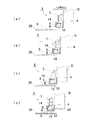
以下本発明を実施するための最良の形態について説明する。図1は、本発明に係る扉止め装置1の外観および使用状態を簡略的に表した説明図である。
扉止め装置1は、回動する扉Dの下端部に取り付けられるストッパー本体2と、扉Dの開位置(停止位置)においてストッパー本体2と係合するフラップ3によって構成されている。当該フラップ3は、ストッパー本体2が移動する軌跡上の床面に設けられている。図1(a)はストッパー本体2とフラップ3が離間している状態を表し、図1(b)はストッパー本体2とフラップ3が係合し、さらに当該係合状態がロックされている様子を表している。
扉止め装置1は、扉Dの全開によって壁や家具等にぶつかるのを防止するために、扉Dの開動作に制限を設ける装置である。また、ロック操作によって、扉Dを開閉いずれの方向に対しても回動しないように固定することができる装置である。
The best mode for carrying out the present invention will be described below. FIG. 1 is an explanatory view simply showing the appearance and use state of a
The
The
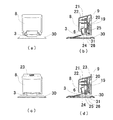
ストッパー本体2は、図2に示すようにホルダー4、磁石5、マグネットホルダー6、ロックピン7およびカバー8の各部材から構成されている。
ホルダー4は、POM(ポリアセタール樹脂)等の硬質樹脂素材によって形成されたハウジングであり、扉Dに対する取り付け面を背面に形成した基部9と、当該基部9の左右両側から前方に向って設けた左右一対の側壁10(10a、10b)を設けたものである。
両側壁10a、10bの前方上部には段部が形成されており、当該段部の先端面にはそれぞれ上下方向に長く形成された長孔11(11a、11b)が取り付け面まで貫通するように設けられている。当該長孔11は、ストッパー本体2を扉Dに対してビス止めするための取り付け孔となっている。
As shown in FIG. 2, the
The
Steps are formed in the upper front portions of the
また、両側壁10a、10bの前方下部には、それぞれ上下方向に沿って長く形成された長孔である軸受け孔12(12a、12b)が設けられている。
当該側壁10aに形成した軸受け孔12aと側壁10bに形成した軸受け孔12bは、ホルダー4背面の取り付け面と平行、かつホルダー4を正常に取り付けた状態でほぼ水平を成す同軸上に配置されている。
当該軸受け孔12は、前記磁石5を保持したマグネットホルダー6を回動可能かつ長孔の範囲内において上下移動可能な状態で軸支するようになっている。
In addition, bearing holes 12 (12a, 12b), which are long holes formed in the vertical direction, are provided at the lower front portions of the
The
The bearing hole 12 supports the
ストッパー本体2は、側壁10a、側壁10bおよび基部9によって囲まれる空間を設けている。そして、当該空間内において磁石5を保持したマグネットホルダー6を回動可能に設けかつロックピン7を上下動可能に設けている。また、中央付近はロックピン7の可動領域となっているので、マグネットホルダー6はロックピン7の可動領域を避けた位置において回動するようになっている。そのため、マグネットホルダー6は平面視において中央部分を避けた略L字形状を成すように形成され、側壁10aに近い位置において前記磁石5を収容した保持部13を回動させるようになっている。
The
磁石5はマグネットホルダー6に設けられた保持部13に嵌着されるようになっている。当該保持部13に対する装着の際、磁石5は磁力線の放出面である磁極面(N極、S極)が略上下方向を向く姿勢で装着されるようになっている。
本実施の形態の場合、磁石5は6面体として形成されており、磁極面は長方形状を成している。そして、磁石5は、長方形状を成した磁極面の長手方向が、マグネットホルダー6の回動方向に沿うように保持部13に保持されている。
また、保持部13も当該配置で磁石5を保持するために、前後方向に沿って長く形成した収容部を設けている。保持部13は、このように前後方向に長く形成されているが、前述のように保持部13を側壁10aと側壁10bとの中間付近に配置するとロックピン7の移動領域と一致してしまうため、保持部13は左右いずれかの側壁10側に近接する偏った位置に設けられている。
The
In this embodiment, the
Further, the holding
マグネットホルダー6は、POM(ポリアセタール樹脂)等の硬質樹脂素材によって形成されており、保持した磁石5が発する磁界を遮断しないようになっている。また、マグネットホルダー6の前方上部の左右には、側壁10a、10bに設けられた軸受け孔12a、12bによって支持される回動軸14(14a、14b)が設けられている。
図3に示した各図は、マグネットホルダー6の外観を表しており、図3(a)は前面側から見た状態である正面図、図3(b)は上方から見た状態の平面図、図3(c)は下方から見た状態の底面図、図3(d)は保持部13部分における側部断面図(A−A’断面)を表している。また、図3(e)は保持部13に磁石5を装着した状態の図3(d)と同位置における側部断面図を表している。
保持部13の底面は、前後方向に長い所定幅の平面を有しており、当該平面が磁石5によって吸着されるフラップ3の吸着面15となっている。また、保持部13の後端には磁石5を入れる開口が形成されるとともに、収容した磁石5の後端と係合し当該磁石5の脱落を防止する弾性を有する係止爪16が設けられている。
The
3 shows the appearance of the
The bottom surface of the holding
次に、マグネットホルダー6に設けた回動軸14と、保持された磁石5の位置関係について説明する。
図3(e)に示すように、磁石5は回動中心である回動軸14に対して、大きく後方側および下方側に偏った位置に設けられている。当該構造は、磁石5によるフラップ3の吸着位置Mを回動中心から離れる後方に向かって設けているものであり、吸着位置Mに対するフラップ3の当接にともなって吸着面15を上方へ向かって回動しやすくすることを可能とするものである。なお、吸着位置Mとは、吸着面15のうち、磁石5の磁極面と近接することでフラップ3の被吸着面(34)を吸着することができる磁力の高い部位を言うものである。
回動軸14は長孔である軸受け孔12に支持されることによって上下方向にも移動可能となっている。当該構造は、フラップ3の吸着にともなって吸着面が回動する際に、当該吸着面15が固定された回転軸でのみ回動するのではなく、上下方向への移動を伴う回動を許容するものである。また、回動軸14は吸着面15よりもかなり高く前方に偏った位
置に設けられているので、吸着面15はその場で回動するのではなく、前後方向への移動を伴って揺動するように回動するものである。当該構造は、マグネットホルダー6の回動角度および高さを自動調節可能とするものであり、扉の接近に伴う吸着面15と被吸着面34との吸着開始から扉を停止させるまでの動的な状態において、両者を最も近接した状態に保つことができるものである。
Next, the positional relationship between the
As shown in FIG. 3 (e), the
The rotating
また、フラップ3は、吸着面15に吸着されてから基部9に設けた当接部31に当接するまで吸着面15の表面を摺動するが、前述したように吸着面15はフラップ3の当接に応じて前後方向への移動を伴って回動するものであるから、僅かではあるが互いの摺動距離を短くすることができるものである。当該摺動距離を短くするということは、吸着面15および被吸着面34双方の摩耗を防ぐことにつながるものであり、安定した吸着性能を維持する効果を高くすることができるものである。
Further, the
前述の通り、ストッパー本体2にはマグネットホルダー6に加えてロックピン7が上下動可能に設けられている。
ロックピン7の左右両側面には、上下方向に亘って溝17が設けられており、ストッパー本体2の側壁10内面に設けた凸条18と係合することによって、上下方向にのみ動作をするようになっている。
また、ロックピン7の裏面には凹部19が設けられており、当該ロックピン7が上昇した位置において、ストッパー本体2に設けた弾性的に突出している弾性凸部20と係合することによって、上昇した状態が保たれるようになっている。
As described above, the
In addition, a
また、ロックピン7の前面には筒状の嵌合凹部21が設けられており、カバー8の内面に形成した嵌合凸部22と嵌合することによって、ロックピン7に対してカバー8を固定している。そして、カバー8を把持して上下動させることによって、これに連動してロックピン7を上下動させるようになっている。
カバー8は、ロックピン7が上昇位置にある場合には、当該ロックピン7およびマグネットホルダー6を含めたストッパー本体2の前面部分をほぼ全て覆うようになっている。また、ロックピン7を下降させた場合にはストッパー本体2の基部9上部に形成した銘板部23を露出させるとともに、ストッパー本体2の下方に対してロックピン7の先端を突出させるようになっている。本実施の形態では、銘板部23には「LOCK」の文字が刻印若しくは凸文字として形成されており(図6(c)参照)、当該文字の表示によって扉が開閉いずれの方向にも回動しないように固定されていることを使用者に視認させることができるようになっている。
Further, a cylindrical
When the
ロックピン7の下端には、フラップ3に形成した孔24内に挿入される先端部25と、当該先端部25に形成した後方側に突出する鈎状の突出部26が設けられている。当該突出部26は、フラップ3に形成した孔24の先端側内縁35と係合することによってフラップ3を保持し、これにより扉Dの停止状態を維持するようになっている。
At the lower end of the
前記フラップ3は、鉄等の磁石に吸着される磁性体金属によって形成された略矩形の板状の部材として形成されており、末端部32に回動中心となる回動軸27を設けるとともに、他端である先端33を磁石の吸着によって回動する自由端としたものである。フラップ3の先端側中央には、前述した孔24が設けられている。当該孔24は、先端33側にフラップ3の先端縁と平行な直線上の縁部(先端側内縁)35を有し、回動軸27側に向かって半円形の後縁部を有した蒲鉾状の孔として形成されている。
また、当該孔24の側部には、フラップ3の長手方向に沿う所定幅の平面部が設けられている。当該平面部は、少なくとも前述した磁石5の横幅(短手方向)程度の横幅を有するように形成された部位であり、マグネットホルダー6の吸着部15によって吸着される被吸着面34となっている。
なお、本実施の形態におけるフラップ3は、ロックピン7との係合用に前記孔24を設けたものであるが、必ずしも孔である必要はない。すなわち、前記先端側内縁35に相当するロックピン7との係合部を有し、かつ前記被吸着面34を有するものであれば、コ字状に切り欠いた切欠部を設け、当該切欠部にロックピン7の先端を挿通させるように構成しても差し支えのないものである。
The
Further, a flat portion having a predetermined width along the longitudinal direction of the
Note that the
当該フラップ3は、床面にビス止めされるベース28の軸受け29によって回動可能に保持される。また、ベース28にフラップ3を保持した後、その上部からベースカバー30を装着する。ベースカバー30は、ベース28固定用のビス(図示せず)、軸受け29、磁石に吸着されていない状態のフラップ3等の種々の突出部分を覆うものである。
The
次に、扉止め装置1が動作する様子を図4に示した説明図を用いて説明する。
図4(a)は、ストッパー本体2を取り付けた扉Dが、フラップ3を覆うベースカバー30に接近しつつある状態を表しており、マグネットホルダー6に装着した磁石5の磁力が、まだフラップ3に対して強く作用していない状態を表している。すなわち、図4(a)は、フラップ3を吸着する前におけるストッパー本体2の初期状態を表している。
当該初期状態では、ストッパー本体2のマグネットホルダー6は、当該マグネットホルダー6の重心位置および装着された磁石5の位置および自重によって、可動範囲内において回動軸14を中心に下方に向かって回動している。そして、当該初期状態では、マグネットホルダー6の底面に形成された前後方向に長い吸着面15が、水平面よりも扉Dの開方向側を向くように傾いている。
吸着面15の内部には、S極若しくはN極が配置されるように磁石5が装着されているので、吸着面15を介して強く磁界が生じるようになっている。そして、当該磁界は吸着面15に対して直角を為す方向に強く生じるので、当該吸着面15が向く方向に対して強い吸着力を発揮する。
Next, how the
FIG. 4A shows a state in which the door D to which the
In the initial state, the
Since the
図4(a)に示した初期状態における吸着面15は、フラップ3に接近する前の状態で、すでにフラップ3側を向くように傾いている。その結果、ストッパー本体2がフラップ3に接近した場合、吸着面15が真下若しくは他の方向を向いている場合と比較して、より遠い位置からフラップ3に対して磁力による吸着力を作用させることができるようになっている。
The
図4(b)は扉Dの近接に伴って、フラップ3の先端が傾けられた吸着面15に対して引きつけられた状態を表している。
仮に、吸着面15が前方に向かって傾くことが無く、水平に設けられている(吸着面15が真下を向いている)とすると、図4(b)に示した状態と比較してフラップ3の先端と磁力が強い吸着面15との距離が遠くなる。図5(a)は、扉Dとフラップ3の距離が図4(b)に示した状態と同じ場合において、吸着面15が真下を向いている場合を表している。この場合、フラップ3の先端が、まだ磁石5の強い磁界(M付近)の中に入っていないことがわかる(図5(b)参照)。すなわち、図5のように吸着面15が真下を向いていると、フラップ3を吸着するためにはフラップ3と扉Dがもう少し接近する必要があるということである。言い方を変えると、扉Dの接近に伴うフラップ3の反応が遅く、吸着が遅れる可能性が高くなるということである。
FIG. 4B shows a state in which the front end of the
If the
図4(c)はフラップ3の先端が吸着面15に対して引きつけられたまま、扉Dとフラップ3の距離がさらに近接した状態を表している。この過程では、フラップ3の先端が吸着面15上を摺りながら移動することになるので、マグネットホルダー6には回動軸14を中心として磁石5を持ち上げる回転力が作用する。また、磁石5の磁力によってフラップ3を吸着する力が高まり、吸着面15とフラップ3の上面を密着させるような磁力が生じ、フラップ3との位置関係に応じてマグネットホルダー6が回動する。
また、吸着面15とフラップ3が密着しようとする力は、扉を床面に取り付けられたフラップ側へ引き込む力としても作用するので、扉を安定した停止位置まで移動させる効果も有している。
FIG. 4C shows a state in which the distance between the door D and the
Moreover, since the force which the adsorption |
図4(d)は、フラップ3が吸着面15に対して引きつけられたまま、ストッパー本体2の当たり面31に先端33が当接した状態を表している。この状態は、フラップ3によって扉Dの開方向への移動が完全に停止された状態であり、かつ吸着面15の全面とフラップ3上面の被吸着面34がほぼ密着した状態である。
当り面31にフラップ3の先端33が当接する位置では、マグネットホルダー底面(吸
着面15)とフラップ3が平行になり面接触するように構成されているので、前述した引き込む力によって確実に一定の位置まで扉が引き込まれるようになっている。そして、ロック付きの場合には、扉が一定の場所に停止することでロックピン7がフラップの孔24に確実に入るようになっている。
FIG. 4D shows a state in which the
At the position where the
図6はロックピン7の動作を説明するための説明図である。
図6(a)および図6(b)は、カバー8および当該カバー8に連動したロックピン7が上昇位置(非ロック状態)にある場合のストッパー本体2とフラップ3を表した正面図および同状態の断面図を表している。
ロックピン7の上昇および下降は、カバー8を把持して上下に移動させることによって行われる。一定以上の扉Dの開動を制限するのみで特に扉Dを固定する必要がないのであれば、ロックピン7を上昇させた図6(a)および図6(b)に示した状態にしておく。この状態は、扉Dが制止位置に近づくと磁石5の作用によってフラップ3を吸着し、フラップ3の先端をストッパー本体2の当たり面31に当接させることで扉Dの回動を停止させるものである。また、磁石5による吸着力を上回る力で扉Dを閉じ方向に回動させると、磁石5とフラップ3の吸着が解除され扉Dを閉じることができる状態である。
ロックピン7の上昇位置では、ロックピン7の背面に形成した凹部19と、フレームとなる基部9に形成した弾性凸部20による係脱可能な係合によってロックピン7を保持することができるようになっている。
FIG. 6 is an explanatory diagram for explaining the operation of the
FIGS. 6A and 6B are a front view and a front view showing the
The
At the raised position of the
また、前記フラップ3の先端をストッパー本体2の当たり面31に当接させた状態では、フラップ3に設けた孔24とロックピン7下端の先端部25が上下に対向する位置関係となっている。すなわち、ロックピン7を下降させると先端部25がフラップ3の孔24内に挿通され、フラップ3によって扉Dの移動が制限された状態になるものである。
図6(c)および図6(d)は、カバー8および当該カバー8に連動したロックピン7が下降(ロック状態)した場合におけるストッパー本体2とフラップ3を表した正面図および同状態の断面図を表している。
Further, in a state where the tip of the
6 (c) and 6 (d) are a front view showing the
当該ロック状態では、扉Dの閉方向への移動に伴うフラップ3との乖離を、孔24内に挿通したロックピン7の先端部25によって制限するようになっている。このロック状態では、フラップ3は磁石5によって上方に引きつけられているので、ロックピン7の先端部25から抜け落ちないようになっている。また、先端部25には、基部9側に向かって突出する突出部26が設けられており、フラップ3の離脱を妨げる鈎として作用するので、より確実にロック状態を維持することができるようになっている。
In the locked state, the deviation from the
本発明は、扉の回動を規制する扉止め装置として利用可能である。 The present invention can be used as a door stopper device that restricts the rotation of the door.
D 扉
1 扉止め装置
2 ストッパー本体
3 フラップ
4 ホルダー
5 マグネット
6 マグネットホルダー
7 ロックピン
8 カバー
9 基部
10(10a、10b) 側壁
11(11a、11b) 長孔
12(12a、12b) 軸受け孔
13 保持部
14(14a、14b) 回動軸
15 吸着面
16 係止爪
17 溝
18 凸条
19 凹部
20 弾性凸部
21 嵌合凹部
22 嵌合凸部
23 銘板部
24 孔
25 先端部
26 突出部
27 回動軸
28 ベース
29 軸受け
30 ベースカバー
31 当たり面(当接部)
32 末端部
33 先端
34 被吸着面
35 縁部(先端側内縁)
3
32
Claims (6)
背面に扉に対する取付面を形成するとともに、前記フラップの先端を当接させる当接部を前面側に設けたハウジングと、
前記ハウジングの前方部において回動可能に軸支されたマグネットホルダーを有し、
前記マグネットホルダーには、前記フラップの長手方向に沿って長く形成した磁石の保持部と、磁力によって前記フラップを吸着する吸着面を前記保持部を形成する底壁の裏面によって形成し、
さらに、前記フラップを吸着する以前の初期状態では、前記吸着面が前記ハウジングの前方に向かって傾斜するように前記マグネットホルダーが下方に向かって回動した状態で停止していることを特徴とする扉止め装置。 A plate-like flap that can be adsorbed by a magnet that pivotally supports the end portion and is configured as a free end that can turn the tip;
A housing that forms a mounting surface for the door on the back surface, and has a contact portion on the front surface side that contacts the tip of the flap;
A magnet holder pivotally supported at the front portion of the housing;
The magnet holder is formed with a magnet holding portion formed long along the longitudinal direction of the flap, and a suction surface for attracting the flap by magnetic force by the back surface of the bottom wall forming the holding portion,
Furthermore, in the initial state before the flap is attracted, the magnet holder is stopped in a state where the magnet holder is rotated downward so that the attracting surface is inclined toward the front of the housing. Door stop device.
当該孔若しくは切り欠きに対して出没可能なロックピンを前記ハウジングに対して上下動可能に設けたことを特徴とする請求項1〜3の何れかに記載の扉止め装置。 While providing a hole or notch penetrating front and back on the front end side of the flap,
The door stopper according to any one of claims 1 to 3, wherein a lock pin capable of moving up and down with respect to the hole or notch is provided to be movable up and down with respect to the housing.
当該孔若しくは切り欠きに対して出没可能な先端部を有したロックピンを前記ハウジングに対して上下動可能に設け、
前記吸着面が主としてフラップの前記被吸着面と接し、かつ前記ロックピンの上下動を妨げないように前記マグネットホルダーを設けたことを特徴とする請求項1〜5の何れかに記載の扉止め装置。 Provided along the longitudinal direction a suction surface having a width at least as large as the lateral width of the magnet held in the magnet holder on the tip side of the flap, and provided a hole or notch penetrating the front and back.
A lock pin having a tip that can be projected and retracted with respect to the hole or notch is provided to be movable up and down with respect to the housing.
The door stopper according to claim 1, wherein the magnet holder is provided so that the attracting surface mainly contacts the attracted surface of a flap and does not hinder the vertical movement of the lock pin. apparatus.
Priority Applications (1)
| Application Number | Priority Date | Filing Date | Title |
|---|---|---|---|
| JP2008215617A JP5271004B2 (en) | 2008-08-25 | 2008-08-25 | Door stop device |
Applications Claiming Priority (1)
| Application Number | Priority Date | Filing Date | Title |
|---|---|---|---|
| JP2008215617A JP5271004B2 (en) | 2008-08-25 | 2008-08-25 | Door stop device |
Publications (2)
| Publication Number | Publication Date |
|---|---|
| JP2010048053A true JP2010048053A (en) | 2010-03-04 |
| JP5271004B2 JP5271004B2 (en) | 2013-08-21 |
Family
ID=42065339
Family Applications (1)
| Application Number | Title | Priority Date | Filing Date |
|---|---|---|---|
| JP2008215617A Active JP5271004B2 (en) | 2008-08-25 | 2008-08-25 | Door stop device |
Country Status (1)
| Country | Link |
|---|---|
| JP (1) | JP5271004B2 (en) |
Cited By (4)
| Publication number | Priority date | Publication date | Assignee | Title |
|---|---|---|---|---|
| CN103334656A (en) * | 2013-07-11 | 2013-10-02 | 苏州工业园区设计研究院股份有限公司 | Foot-operated positioning apparatus for side hung door |
| JP2017066839A (en) * | 2015-10-02 | 2017-04-06 | 株式会社システックキョーワ | Door stopper |
| CN107675972A (en) * | 2017-11-02 | 2018-02-09 | 李艳青 | One kind fastening door-inhale |
| JP6343691B1 (en) * | 2017-01-18 | 2018-06-13 | 余合ホーム&モビリティ株式会社 | Door stopper for hinged door and hinged door set provided with the same |
Citations (2)
| Publication number | Priority date | Publication date | Assignee | Title |
|---|---|---|---|---|
| JP2003328627A (en) * | 2002-05-09 | 2003-11-19 | Yagi:Kk | Door stop |
| JP2005120668A (en) * | 2003-10-16 | 2005-05-12 | Inoue Kanamono Kk | Stopper for outset sliding door |
-
2008
- 2008-08-25 JP JP2008215617A patent/JP5271004B2/en active Active
Patent Citations (2)
| Publication number | Priority date | Publication date | Assignee | Title |
|---|---|---|---|---|
| JP2003328627A (en) * | 2002-05-09 | 2003-11-19 | Yagi:Kk | Door stop |
| JP2005120668A (en) * | 2003-10-16 | 2005-05-12 | Inoue Kanamono Kk | Stopper for outset sliding door |
Cited By (5)
| Publication number | Priority date | Publication date | Assignee | Title |
|---|---|---|---|---|
| CN103334656A (en) * | 2013-07-11 | 2013-10-02 | 苏州工业园区设计研究院股份有限公司 | Foot-operated positioning apparatus for side hung door |
| JP2017066839A (en) * | 2015-10-02 | 2017-04-06 | 株式会社システックキョーワ | Door stopper |
| JP6343691B1 (en) * | 2017-01-18 | 2018-06-13 | 余合ホーム&モビリティ株式会社 | Door stopper for hinged door and hinged door set provided with the same |
| JP2018115456A (en) * | 2017-01-18 | 2018-07-26 | 余合ホーム&モビリティ株式会社 | Door stopper for hinged door and hinged door set provided with the same |
| CN107675972A (en) * | 2017-11-02 | 2018-02-09 | 李艳青 | One kind fastening door-inhale |
Also Published As
| Publication number | Publication date |
|---|---|
| JP5271004B2 (en) | 2013-08-21 |
Similar Documents
| Publication | Publication Date | Title |
|---|---|---|
| JP5271004B2 (en) | Door stop device | |
| JP2008144568A (en) | Door lock device for door outer handle in side collision | |
| JP2003262062A (en) | Sliding door lock | |
| JP5376965B2 (en) | Anti-sway device for hanging sliding doors | |
| JP2013036233A (en) | Door handle device | |
| JP5329146B2 (en) | Door to door | |
| JP5275002B2 (en) | Door stopper | |
| JP4510606B2 (en) | Hinge for game console | |
| JP4207822B2 (en) | Handle device | |
| JP2005120668A (en) | Stopper for outset sliding door | |
| JPH11287062A (en) | Member for floor face in door stop device, and door stop device | |
| JP5140404B2 (en) | Door stop device | |
| JP2004081242A (en) | Locking device in game machine | |
| JP2013189774A (en) | Operation mechanism of lid | |
| JP2007285053A (en) | Door stop device | |
| JP3140207U (en) | Per door | |
| JP3582506B2 (en) | Door stopper | |
| JP2007303226A (en) | Latch device and fire extinguisher housing box | |
| JP2008012057A (en) | Hinge structure of game machine | |
| JP2003020848A (en) | Door positioning device | |
| JPH0575381U (en) | Pivot hinge | |
| JP2024014346A (en) | door stop device | |
| JP2002004690A (en) | Oscillatory stop device of door | |
| JP2003184398A (en) | Door stop | |
| JP2005120756A (en) | Cover sliding mechanism for underfloor storage |
Legal Events
| Date | Code | Title | Description |
|---|---|---|---|
| A621 | Written request for application examination |
Free format text: JAPANESE INTERMEDIATE CODE: A621 Effective date: 20110622 |
|
| A977 | Report on retrieval |
Free format text: JAPANESE INTERMEDIATE CODE: A971007 Effective date: 20120919 |
|
| A131 | Notification of reasons for refusal |
Free format text: JAPANESE INTERMEDIATE CODE: A131 Effective date: 20121009 |
|
| A521 | Request for written amendment filed |
Free format text: JAPANESE INTERMEDIATE CODE: A523 Effective date: 20121107 |
|
| TRDD | Decision of grant or rejection written | ||
| A01 | Written decision to grant a patent or to grant a registration (utility model) |
Free format text: JAPANESE INTERMEDIATE CODE: A01 Effective date: 20130507 |
|
| A61 | First payment of annual fees (during grant procedure) |
Free format text: JAPANESE INTERMEDIATE CODE: A61 Effective date: 20130510 |
|
| R150 | Certificate of patent or registration of utility model |
Ref document number: 5271004 Country of ref document: JP Free format text: JAPANESE INTERMEDIATE CODE: R150 Free format text: JAPANESE INTERMEDIATE CODE: R150 |
|
| R250 | Receipt of annual fees |
Free format text: JAPANESE INTERMEDIATE CODE: R250 |
|
| R250 | Receipt of annual fees |
Free format text: JAPANESE INTERMEDIATE CODE: R250 |
|
| R250 | Receipt of annual fees |
Free format text: JAPANESE INTERMEDIATE CODE: R250 |