JP2010046987A - File - Google Patents
File Download PDFInfo
- Publication number
- JP2010046987A JP2010046987A JP2008215511A JP2008215511A JP2010046987A JP 2010046987 A JP2010046987 A JP 2010046987A JP 2008215511 A JP2008215511 A JP 2008215511A JP 2008215511 A JP2008215511 A JP 2008215511A JP 2010046987 A JP2010046987 A JP 2010046987A
- Authority
- JP
- Japan
- Prior art keywords
- spine
- cover
- substrate portion
- substrate
- binding
- Prior art date
- Legal status (The legal status is an assumption and is not a legal conclusion. Google has not performed a legal analysis and makes no representation as to the accuracy of the status listed.)
- Granted
Links
- 239000000758 substrate Substances 0.000 claims abstract description 239
- 238000000034 method Methods 0.000 claims abstract description 12
- 230000001105 regulatory effect Effects 0.000 claims abstract 2
- 239000011230 binding agent Substances 0.000 abstract 2
- 230000008859 change Effects 0.000 description 12
- 230000007246 mechanism Effects 0.000 description 11
- 230000035515 penetration Effects 0.000 description 9
- 238000003780 insertion Methods 0.000 description 8
- 230000037431 insertion Effects 0.000 description 8
- 230000000694 effects Effects 0.000 description 6
- 230000000149 penetrating effect Effects 0.000 description 6
- 239000000463 material Substances 0.000 description 5
- 230000002093 peripheral effect Effects 0.000 description 4
- 230000008275 binding mechanism Effects 0.000 description 3
- 210000000078 claw Anatomy 0.000 description 2
- 239000011162 core material Substances 0.000 description 2
- 230000007704 transition Effects 0.000 description 2
- 239000004743 Polypropylene Substances 0.000 description 1
- 230000009471 action Effects 0.000 description 1
- 239000000853 adhesive Substances 0.000 description 1
- 230000001070 adhesive effect Effects 0.000 description 1
- 230000008901 benefit Effects 0.000 description 1
- 239000010410 layer Substances 0.000 description 1
- 239000002184 metal Substances 0.000 description 1
- 238000005457 optimization Methods 0.000 description 1
- -1 polypropylene Polymers 0.000 description 1
- 229920001155 polypropylene Polymers 0.000 description 1
- 230000002787 reinforcement Effects 0.000 description 1
- 239000002356 single layer Substances 0.000 description 1
- 229920003002 synthetic resin Polymers 0.000 description 1
- 239000000057 synthetic resin Substances 0.000 description 1
Images

Landscapes
- Sheet Holders (AREA)
Abstract
Description
本発明は、紙葉類の最大綴じ量を調節できる綴じ具を備えたファイルに関する。 The present invention relates to a file including a binding tool that can adjust the maximum binding amount of paper sheets.
書類や紙片等の紙葉類を綴じ具によって綴じるようにしたファイルが各種知られている。従来のファイルでは、綴じ具に紙葉類を密にして綴じると、ファイルの見開きが困難になるといった問題があった。また、これを改善すべく、綴じ具間の寸法を広くすると、背幅を広くとらなければならないといった問題があった。 Various files are known in which paper sheets such as documents and paper pieces are bound by a binding tool. In the conventional file, there is a problem that it is difficult to spread the file when paper sheets are densely bound in the binding tool. Moreover, when the dimension between the binding tools is widened in order to improve this, there is a problem that the spine must be widened.
上記問題を解決すべく開発された技術として、相対的に移動可能な表表紙部及び裏表紙部と、背幅を調整可能な表表紙側背幅調整部及び裏表紙側背幅調整部と、移動変化に応じて綴じ込み可能寸法を変化可能な綴じ具と、表表紙部と裏表紙部との移動を禁止するロック手段、ロック手段を、ロック状態又はロック解除状態へ操作可能な操作手段を備えるファイルが開示されている(特許文献1参照。)。特許文献1に記載の技術によれば、表表紙部と裏表紙部とを、綴じ具の綴じ込み可能寸法が大きくなる方向に移動させることができる。従って、綴じる紙葉類が多い場合でも、綴じ具の綴じ込み可能寸法を広くして紙葉類を好適に見開くことができる。
しかしながら、特許文献1に記載のファイルは、表表紙部と裏表紙部とが別部品として構成され、背幅を調整するための構成として、表表紙と裏表紙の夫々に、表表紙側背幅調整部と裏表紙側背幅調整部が設けられており、さらに、表表紙と裏表紙の分解を防止するためのロック手段や、このロック手段を操作する操作手段が必須の構成であるだけでなく、各構成要素の構造が従来の他のファイルと比較して複雑である。
また、特許文献1に記載の技術では、背表紙が二層に重なっているために一層構成の(一枚構成の)背表紙のファイルに比べて表紙体の材料が多く必要となり、また、上記の通り各構成要素が従来の他のファイルよりも複雑であるため部品点数が多くなったり材料が多くなったりする。
特許文献1に記載のファイルは、一つの(一枚構成の)背表紙によって構成される一般的なファイルに比べて背表紙が当然に厚くなってしまい、従来の他のファイルと同等の強度と背表紙の薄さを実現するためには従来とは異なる特殊な材料を選択する等の必要がある。
However, in the file described in
Further, in the technique described in
The file described in
このような問題は、特許文献1に記載のファイルに限らず、綴じ具の最大綴じ量(綴じられる紙葉類全てをあわせた厚み)を変更可能なファイル(以下、「綴じ量調整可能ファイル」と表記する。)は多かれ少なかれ上記同等の問題が指摘されており、最大綴じ量が変更不能な一般的なファイル(以下、単に「一般的なファイル」と表記する。)と比べると値段が高くなってしまっている。そのため、綴じ量調整可能ファイルは、一般的なファイルと比較すると、機能的には優れているにも関わらず市場規模は圧倒的に小さいものとなっている。
Such a problem is not limited to the file described in
また、特許文献1に記載のファイルなどの従来の綴じ量調整可能ファイルは、綴じ具の最大綴じ量を変更する作業が面倒であるという問題もあった。
Further, the conventional binding amount adjustable file such as the file described in
本発明は、上記問題に鑑みてなされたものであり、綴じ量を調整可能な綴じ具を有する
ファイルであって、従来よりも簡易な構成で綴じ量を調整できるファイルに関する技術を提供することを課題とする。
The present invention has been made in view of the above problems, and is a file having a binding tool capable of adjusting the binding amount, and provides a technique relating to a file capable of adjusting the binding amount with a simpler configuration than conventional ones. Let it be an issue.
本発明に係るファイルは、綴じ具のベース(基板部)が背幅方向に少なくとも2分割され(第一基板部及び第二基板部を備え)、第一基板部と第二基板部にはそれぞれ第一串部、第二串部が設けられている。第一串部及び第二串部は、それぞれ、開放端側で他方の串部と当接したり嵌合したり係合したりするなど係りあうことで、これらの串部に綴じ孔で貫通された紙葉類が綴じ具(串部)から抜け落ちないようにされている。第一串部及び第二串部が係りあう方法は種々の方法を採用し得るが、例えば一方が串状部で他方がパイプ状部とされ、串状部がパイプ状部の中空部に挿入されることで係りあういわゆるパイプ式機構を採用するなどして、各串部の基端部(上記開放端とは反対側)が離れた場合であっても綴じられた書類等が脱落しない綴じ量変更機能を備えた串部(第一串部及び第二串部)が採用される。 In the file according to the present invention, the base (substrate part) of the binding tool is divided into at least two parts in the spine width direction (including the first substrate part and the second substrate part), and the first substrate part and the second substrate part are respectively A first skewer and a second skewer are provided. The first skewer portion and the second skewer portion are respectively penetrated into the skewer portions by a binding hole by being brought into contact with, engaged with, or engaged with the other skewer portion on the open end side. Paper sheets are prevented from falling out of the binding tool (skewer). Various methods can be adopted for the method of engaging the first skewer and the second skewer. For example, one is a skewer and the other is a pipe, and the skewer is inserted into the hollow part of the pipe. This is a binding that does not drop out the bound documents even when the base end of each skewer part (the side opposite to the open end) is separated, such as by adopting a so-called pipe mechanism. A skewer (first skewer and second skewer) having a function of changing the amount is employed.
第一基部及び第二基部は、少なくとも一方が背表紙に対して背幅方向に相対的に移動可能な可動基板部とされている。すなわち、可動基板部は、他方の基板部に対して相対的に移動可能である。可動基板部でない基板部は、背表紙に対して相対的に移動不能に固定されている。可動基板部が相対移動可能な仕組みは以下の通りである。 At least one of the first base portion and the second base portion is a movable substrate portion that can move relative to the spine in the spine width direction. That is, the movable substrate part is movable relative to the other substrate part. A substrate portion that is not a movable substrate portion is fixed so as not to move relative to the spine. The mechanism by which the movable substrate part can be relatively moved is as follows.
可動基板部には貫通部が設けられ、背表紙にも当該貫通部に対応した位置に孔部が設けられている。固定装置は、可動基板部と背表紙とが重ね合わされた状態において、可動基板部における貫通部周辺部並びに背表紙における孔部周辺部と係合することで、可動基板部が背表紙から離れないようにする固定具である。このような固定具としては種々の構成を採用し得るが、例えば以下の構成も採用することができる。 The movable substrate portion is provided with a through portion, and the back cover is also provided with a hole at a position corresponding to the through portion. In the state where the movable substrate portion and the back cover are overlapped, the fixing device engages with the peripheral portion of the through portion of the movable substrate portion and the peripheral portion of the hole portion of the spine cover, so that the movable substrate portion does not separate from the spine. It is a fixing tool. As such a fixture, various configurations can be adopted. For example, the following configurations can also be adopted.
(イ)固定装置が貫通部を貫通可能な頸部と貫通不能な頭部を有する挿通部を備え、頸部の先端側(頭部とは反対側)に係合部が設けられるとともに、孔部が貫通孔である構成。この構成において、当該固定装置の挿通部を係合部側から貫通部に挿通し、さらに孔部に挿通させ、背表紙側における可動基板部と接する面とは反対側面(表側/外側)に係合部を位置させる。そして、係合部を背表紙の表側(すなわち孔部の周辺部)と係合させ、挿通部の可動基板部に対する背表紙長手方向の相対位置が動かないように固定することで、背表紙及び可動基板部は係合部及び頭部に挟持され、可動基板部が背表紙から離れない状態が保たれる(固定される。)。 (A) The fixing device includes an insertion part having a neck part that can penetrate the penetration part and a head part that cannot penetrate, and an engagement part is provided on the tip side (opposite side of the head part) of the neck part, The part is a through hole. In this configuration, the insertion portion of the fixing device is inserted from the engagement portion side into the penetration portion, and further inserted into the hole portion, and is engaged with the side surface (front side / outside) opposite to the surface in contact with the movable substrate portion on the spine cover side. Position the joint. Then, by engaging the engaging portion with the front side of the spine (that is, the peripheral portion of the hole) and fixing the insertion portion so that the relative position in the longitudinal direction of the spine with respect to the movable substrate portion does not move, The movable substrate portion is sandwiched between the engaging portion and the head, and the state where the movable substrate portion is not separated from the spine is kept (fixed).
(ロ)上記(イ)の構成において、背表紙の表側と内側との間に設けられた空間部と連通した凹部、すなわち凹部と空間部を孔部とした構成。この構成においては、挿通部の係合部側を貫通部に貫通させ、次いで凹部に進入させ、係合部が空間部と係合した状態において、固定装置が可動基板部に対して背表紙長手方向に相対移動しないように固定される。これにより、背表紙及び可動基板部は係合部及び頭部に挟持され、可動基板部が背表紙から離れない状態が保たれる(固定される。)。 (B) In the configuration of (a) above, a recess communicating with a space provided between the front side and the inside of the spine, that is, a configuration in which the recess and the space are holes. In this configuration, when the engaging portion side of the insertion portion is passed through the penetrating portion and then entered into the concave portion, and the engaging portion is engaged with the space portion, the fixing device is long in the spine with respect to the movable substrate portion. It is fixed so that it does not move relative to the direction. As a result, the spine and the movable substrate are sandwiched between the engaging portion and the head, and the movable substrate is kept (fixed) from being separated from the spine.
その他、
・固定装置が背表紙の表側から孔部を貫通し、頭部が可動基板部における貫通部周辺部と係合する構成や、
・裏当て部材を背表紙の表側における孔部近傍に配置し、貫通部及び孔部を貫通した固定装置の頭部が裏当て部材と係合する構成(下記の発明を実施するための最良の形態欄に記載した構成)など、
も採用し得る。
Other,
-A structure in which the fixing device penetrates the hole from the front side of the spine, and the head engages with the peripheral part of the through part in the movable substrate part,
A configuration in which the backing member is arranged near the hole on the front side of the back cover, and the penetration portion and the head of the fixing device penetrating the hole are engaged with the backing member (the best mode for carrying out the following invention) Configuration described in the form column)
Can also be adopted.
そして、このファイルは、固定装置における貫通部及び孔部の挿通部分の背幅方向の幅が、貫通部及び孔部に挿通可能な幅であり、かつ、貫通部及び孔部の一方は他方よりも背幅方向の幅が狭い。つまり、固定装置の上記挿通部分は、貫通部及び孔部の少なくとも一方内において、背表紙長手方向の相対移動は規制され、背幅方向の相対移動は許容されている。 In this file, the width in the back width direction of the insertion part of the penetration part and the hole part in the fixing device is a width that can be inserted into the penetration part and the hole part, and one of the penetration part and the hole part is more than the other. Is narrow in the width direction. That is, in the insertion portion of the fixing device, relative movement in the longitudinal direction of the spine is restricted and relative movement in the spine width direction is allowed within at least one of the through portion and the hole portion.
そのため、固定装置は、可動基板部を背表紙から離れないようにした状態において、背表紙及び可動基板部の少なくとも一方に対して背幅方向の所定範囲内で相対移動ができる。したがって、可動基板部は背表紙に対して背幅方向に相対的に移動可能である(他の基板部に近づく方向・遠ざかる方向に背表紙上を相対移動可能である。)。
なお、上記のように可動基板部が相対移動した際に、紙葉類を綴じる機構(綴り機構)が紙葉類を綴じた状態を保つようにするため、綴り機構は上記したようにパイプ式機構等が好適に採用される。
Therefore, the fixing device can move relative to at least one of the back cover and the movable substrate portion within a predetermined range in the back width direction in a state where the movable substrate portion is not separated from the back cover. Therefore, the movable substrate portion can move relative to the spine in the back width direction (relative movement on the spine in a direction approaching or moving away from the other substrate portion).
In addition, when the movable substrate part moves relatively as described above, the binding mechanism is a pipe type as described above in order to keep the sheet binding mechanism (binding mechanism) in a state in which the sheets are bound. A mechanism or the like is preferably employed.
また、貫通部及び孔部の幅を上記のように設定せず、両者の幅をほぼ同じにしてもよい。この場合、固定装置(挿通部)の貫通部に配置される部位の幅を貫通部の幅よりも狭くし、孔部に配置される部位の幅を孔部の幅よりも狭くすれば、上記同等の作用が得られる。 Further, the widths of the penetrating part and the hole part may not be set as described above, and the widths of both may be substantially the same. In this case, if the width of the part arranged in the penetration part of the fixing device (insertion part) is made narrower than the width of the penetration part, and the width of the part arranged in the hole part is made narrower than the width of the hole part, Equivalent action is obtained.
貫通部及び孔部の少なくとも一方を背幅方向に複数設け、固定装置(挿通部)が挿通される貫通部及び孔部が選択されることで、可動基板部の他の基板部との相対位置が規定されるようにしてもよい。このように構成した場合であっても、固定に用いる貫通部及び孔部を選択するだけで可動基板部と他の基板部との距離を変更することができ、さらに、その距離を上記構成よりも固定的に維持することができる。
なお、この構成であっても、それぞれの貫通部の幅や孔部の幅などを上記のように構成すれば、固定装置によって背表紙から可動基板部が離れないように保たれた状態においても可動基板部と他の基板部との背幅方向の相対距離を変更することができる。
By providing at least one of the penetrating part and the hole part in the back width direction and selecting the penetrating part and the hole part through which the fixing device (insertion part) is inserted, the relative position of the movable substrate part to the other substrate part May be defined. Even in this case, it is possible to change the distance between the movable substrate portion and the other substrate portion only by selecting the through portion and the hole portion used for fixing, and further, the distance can be changed from the above configuration. Can also be kept fixed.
Even in this configuration, if the width of each through portion and the width of the hole portion are configured as described above, even in a state where the movable substrate portion is kept away from the back cover by the fixing device. The relative distance in the spine width direction between the movable substrate portion and another substrate portion can be changed.
上記のように構成されたファイルにおいては、背表紙と表表紙及び/又は裏表紙とを複数のヒンジにより接続するとよい。すなわち、両基板部の相対位置(相対距離)に応じて採用する(折り曲げる)ヒンジを選択すれば、背幅は綴じられている書類等に応じて最小にすることができる。また、従来技術と比較してファイルの構造が極めて単純となるため、最大綴じ量を変更する作業が容易になるだけでなく、故障等の問題発生の可能性を低くすることなども可能となる。 In the file configured as described above, the back cover and the front cover and / or the back cover may be connected by a plurality of hinges. That is, if a hinge that is adopted (bent) is selected according to the relative position (relative distance) between the two substrate portions, the spine width can be minimized according to the bound document. In addition, since the file structure is extremely simple compared to the prior art, not only can the work of changing the maximum binding amount be facilitated, but also the possibility of problems such as failures can be reduced. .
本発明によれば、綴じ量を調整可能な綴じ具を有するファイルであって、従来よりも簡易な構成で綴じ量を調整できるファイルに関する技術を提供することができる。 ADVANTAGE OF THE INVENTION According to this invention, it is a file which has a binding tool which can adjust a binding amount, Comprising: The technique regarding the file which can adjust a binding amount with a simpler structure than before can be provided.
次に、本発明に係るファイルの実施形態について図面に基づいて説明する。
<構成>
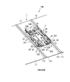
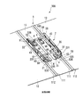
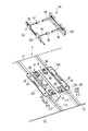
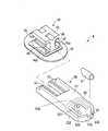
図1は、ファイル100の非拡張状態の斜視図を示す。図2は、ファイル100の拡張状態の斜視図を示す。図3は、図2における綴じ具2から紙葉類を実際に綴じる(紙葉類の綴じ孔に挿通されるとともに、抜け落ちないようにする)第一串部としての第一綴り部24と第二串部としての第二綴り部34を取り外した状態を示す。図4は、図3に示すファイル100のさらに他の構成要素を分解した分解斜視図である。図5は、固定装置4を図1等よりも拡大して示した斜視図である。
Next, an embodiment of a file according to the present invention will be described with reference to the drawings.
<Configuration>
FIG. 1 shows a perspective view of the
ファイル100は、表紙体1と、綴じ具2と、固定装置4とによって構成されている。
ファイル100は、綴じ量に応じて、綴じ具2を構成する第一基板部21と第二基板部31との間隔を調整すること、すなわち綴じ具2の綴じ幅の調整が可能である(最大綴じ量を変更することができる。)。また、表紙体1には、外側薄肉ヒンジ112と内側薄肉ヒンジ111が設けられており、綴じ具2の閉じ幅に応じて、表紙体1を構成する背表紙11の背幅を調整することが可能である。なお、本実施形態の説明では、非拡張状態とは、図1に示すように、第一基板部21と第二基板部31との間隔が最も狭い状態を意味する。また、拡張状態とは、第一基板部21と第二基板部31との間隔が拡張された状態を示す。以下、各構成についてさらに詳しく説明する。
The
The
[表紙体]
表紙体1は、背表紙11と、背表紙11の背幅方向の一端部に接続される表表紙12と、背表紙11の背幅方向の他端部に接続される裏表紙13とによって構成されている。なお、本明細書においては、「背幅」とは表表紙12と裏表紙13とを最短距離で結んだ長さであり、「背幅方向」とは当該直線の延在方向である。また、背表紙11における背幅方向と直交する方向を便宜上「背表紙の長手方向」と記載する。
表紙体1は、既存の素材によって構成することができ、例えば、芯材の表面にポリプロピレン等の表皮部材を接着剤等で貼付け、芯材の裏面には紙からなる裏皮部材を貼り付けることで構成することができる。本実施形態では、背表紙11と、背表紙11の背幅方向の両端部に接続される表表紙12及び裏表紙13とが内側薄肉ヒンジ111及び外側薄肉ヒンジ112を介して接続され、表紙体1が一体的に形成されている(一枚構成である。)。
[Cover body]
The
The
背表紙11には、綴じ具2の第一基板部21及び第二基板部31を固定する固定装置4の軸部42(図5参照。)が貫通する背表紙側貫通孔113(孔部)が設けられている。背表紙側貫通孔113は、第一基板部21を取り付ける貫通孔として、表表紙12側に二つ、第二基板部31を取り付ける貫通孔として裏表紙13側に二つ設けられている。また、これら合計四つの背表紙側貫通孔113は、背表紙11の長手方向に所定の間隔をあけて設けられている。なお、この所定の間隔は、第一基板部21又は第二基板部31を背表紙11に安定的に取り付けられる間隔として設定され、第一綴り部24及び第二綴り部34による綴じ量変更機能を考慮して設定される。本実施例では、串状部としての綴り棒25がパイプ状部としてのパイプ部35に嵌合することで紙葉類を綴じるいわゆるパイプ式機構が採用されているため、両者が嵌合し得る範囲を考慮して上記所定の間隔が設定されている。なお、本実施形態においては、第一基板部21及び第二基板部31は、それぞれ背表紙11に対して背幅方向に相対的に移動可能な可動基板部として構成されているため、それぞれ固定装置4によって背表紙11から離れずかつ背表紙において長手方向に相対的に移動することがないように背表紙11に組み付けられる。
In the
背表紙側貫通孔113は、平面視が略矩形である。背表紙側貫通孔113の縦方向(背表紙11の長手方向)の寸法は、固定装置4の軸部42の断面における縦方向の長さとほぼ同じであり、背表紙側貫通孔113の横方向(背表紙11の背幅方向)の寸法は、内側起立片45aと外側起立片45bとの間隔よりも大きく設計されている。すなわち、背表紙側貫通孔113の縦方向の長さは、固定装置4の軸部の縦方向の長さとほぼ一致しており、固定装置4の縦方向への動きが規制されている。一方、背表紙側貫通孔113の横方向の長さは、固定装置4が移動できるよう、固定装置4の内側起立片45aと外側起立片45bの間隔よりも大きく形成されており、背表紙側貫通孔113へ挿入された固定装置4は、背表紙11の背幅方向への移動のみが許容される。
The back cover side through
背表紙側貫通孔113の夫々の近傍には、背表紙11の背幅方向において中心寄りに位置する内側係止孔114と背幅方向において外寄りに位置する外側係止孔115とが設けられている。また、内側係止孔114と外側係止孔115は、背表紙11の背幅方向に延
びる仮想線X軸上に設けられている。また、内側係止孔114は、仮想線Xと直交する仮想線Y1軸上に設けられ、外側係止孔115は、仮想線Xと直交し、かつ仮想線Y1と平行な仮想線Y2軸上に設けられている。内側係止孔114は、非拡張状態において固定装置4の係止突部46を収容し、これにより、非拡張状態における綴じ具2の移動を規制する。一方、外側係止孔115は、拡張状態において固定装置4の係止突部46を収容することで、拡張状態における綴じ具2の移動を規制する。このように、内側係止孔114、外側係止孔115及び係止突起46は、可動基板部の背表紙における背幅方向の位置を任意の位置で固定するための位置調整手段として機能する。
Near each of the spine side through-
表紙体1は、薄肉ヒンジとして、内側薄肉ヒンジ111と外側薄肉ヒンジ112が背表紙11の夫々の背幅方向の端部に並列に設けられている。内側薄肉ヒンジ111は、非拡張状態において表紙体1の回動軸として機能する。外側薄肉ヒンジ112は、拡張状態において表紙体1の回動軸として機能する。すなわち、本実施形態では、綴じ具2の閉じ幅に応じて、背表紙11の背幅を調整することができる。なお、本実施形態では、薄肉ヒンジを端部の夫々に二つ設けたが、薄肉ヒンジの数は特に限定されない。薄肉ヒンジを三つ以上設け、例えば、蛇腹状としてもよい。このように、表表紙12及び裏表紙13の内、背表紙11の背幅に対する中心線を基準として可動基板部が存する側(本実施形態では両側)の表紙は、背表紙との間に複数本のヒンジを介して接続している。
The
[綴じ具]
次に綴じ具2について説明する。綴じ具2は、背表紙11の内側に固定装置4によって固定される第一基板部21と、第一基板部21の外側端部(表表紙12側端部)に第一ヒンジ23を介して接続される第一側板22と、第一側板22と着脱可能な第一綴り部24と、第一基板部21と並行に、背表紙11の内側に固定装置4によって固定される第二基板部31と、第二基板部31の外側端部(裏表紙13側端部)に第二ヒンジ33を介して接続される第二側板32と、第二側板32と着脱可能な第二綴り部34とによって構成されている。綴じ具2の各構成要素は、いずれも金属部材によって構成されている。
[Binding tool]
Next, the
第一基板部21は、平面視が長方形のプレートによって構成され、長手方向に所定の間隔をあけて二つの第一基板部側貫通孔211(貫通部)が形成されている。第一基板部側貫通孔211には、固定装置4の軸部42、内側起立片45a、外側起立片45bが挿入可能である。所定の間隔は、上述した背表紙側貫通孔113の所定の間隔と同じであり、第一基板部側貫通孔211の位置と背表紙側貫通孔113の位置は対応している。
The
第一基板部側貫通孔211は、矩形状であり、背表紙長手方向の長さは固定装置の軸部42における背表紙長手方向の長さと略同じであるため、軸部42が第一基板部側貫通孔211に挿通された固定装置4は、第一基板部21に対する背表紙長手方向の相対移動が規制されている。
また、第一基板部側貫通孔211は、背幅方向の長さは固定装置4の内側起立片45aと外側起立片45bの間隔と略同じである。これにより、固定装置4は、軸部42、内側起立片45a、外側起立片45bが第一基板部側貫通孔211に挿入されると、第一基板部21における背幅方向への相対移動が制限される(固定される。)。すなわち、これらの大きさの設定により、固定装置の可動基板部に対する背幅方向の移動を制限する第一の制限手段が実現されている。
このように、背表紙側貫通孔113は、固定装置4の移動を許容すべく横幅が内側起立片45aと外側起立片45bの間隔よりも大きく形成されていたが、第一基板部側貫通孔211は、横幅も内側起立片45aと外側起立片45bの間隔とほぼ同じ大きさとなっている。換言すると、第一基板部側貫通孔211の横幅は、背表紙側貫通孔113の横幅よりも小さく形成されている。
The first substrate portion side through-
The length in the back width direction of the first substrate portion side through
As described above, the spine side through-
第二基板部31も、基本的には、上述した第一基板部21と同等の機能及び作用効果を有している。すなわち、第二基板部31には、第二基板部側貫通孔311が設けられ、固定装置4の軸部42が挿入可能である。
The
第一側板22には、第一綴り部24が着脱可能である。第一綴り部24は、第一側板22と接続する板状の第一綴り本体部231と、第一綴り本体部231から略直角に立ち上げられた二本の綴り棒25によって構成されている。一方、第二側板32には、第二綴り部34が着脱可能である。第二綴り部34は、第二側板32と接続する板状の第二綴り本体部331と、第二基板から略直角に立ち上げられた二本のパイプ35とによって構成されている。なお、パイプ35の内部には、綴り棒25が挿入可能である。
このようないわゆるパイプ式機構は、両串部の先端同士が係合等する機構と異なり、両者の先端同士の相対距離を変化させても両者がつながった状態にすることができる。すなわち、第一綴り本体部231と第二綴り本体部331との相対距離が変化しても、第一串部としての綴り棒25と第二串部としてのパイプ35とが嵌合した状態とし得、綴じ足の長さを変更する機能(綴じ量変更機能)を備える。なお、より具体的には、パイプ35は、紙葉類の綴じ孔に挿入されることから、綴じ孔よりも小さい外径を有している。綴り棒25は、パイプ35に挿入されるので、その外径がパイプ35の内径よりも小さく設計されている。また、パイプ35の長さは、非拡張状態において先端が第一綴り部24の第一綴り本体部231に達するように設計されている。綴り棒25もパイプ35とほぼ同じ長さに設計されている。このように他の綴り本体部に達した各串部は、当該他の綴り本体部に設けられた図示しない凹部等に嵌るなどすることで、串部先端側を安定的にファイル100に維持される。
A first binding
Such a so-called pipe-type mechanism is different from a mechanism in which the ends of both skewers are engaged with each other, and the two can be connected even if the relative distance between the ends of both is changed. That is, even if the relative distance between the first binding
本実施形態に係るファイル100では、拡張状態におけるパイプ35の不足を補う補助パイプ61が備えられている。補助パイプ61は、合成樹脂によって形成され、外径、内径共にパイプ35と同様に設計されている。また、補助パイプ61の長さは、拡張状態におけるパイプ35の先端から第一綴り部24の第一綴り本体部231までの間隔に基づいて設計されている。本実施形態のパイプ35は、その先端部分にテーパが形成されている。そこで、補助パイプ61の一方の端部は、このテーパに合わせて設計されている。この補助パイプ61は、拡張状態においてパイプ35の先端側に配置されて使用される。これにより、補助パイプ61はテーパ部分においてパイプ35と係り合い、他端において第一綴り本体部231(の凹部等)と係りあうなどすることで、パイプ35の先端がばたついてしまう可能性をより低くし、また、パイプ35の先端と第一綴り部24の第一綴り本体部231との間に紙葉類が挟まってしまったりする可能性を極めて小さくすることができる。
The
なお、補助パイプ61は、非拡張状態においては不要となる。そこで、本実施形態では、固定装置4に設けられた、補助パイプ61を収容する補助パイプ収容部54に補助パイプ61を収容することができる。これにより、非拡張状態における、補助パイプ61の紛失を防止することができる。なお、長さが異なる補助パイプ61を用意することで、第一綴り本体部231と第二綴り本体部331との相対距離に応じて最適な補強が行える。すなわち補助パイプ61を用いてもファイル100の背幅(最大綴じ量)が必要以上に大きくなってしまうことを防止できる。
The
なお、綴じ具2におけるその他の構成要素(例えば第一ヒンジ23、第二ヒンジ33、第一側板22、第一綴り部24の第一綴り本体部212、第二綴り本体部331など)は、公知の技術を適宜用いることができる。
The other components in the binding tool 2 (for example, the first hinge 23, the
[固定部]
次に固定部について説明する。図5に示すように、固定装置4は、ベース部材40と、
スライド部材50とによって構成され、可動基板部としての第一基板部21と第二基板部31を、背表紙11から離れないようにし、背表紙の長手方向の位置を規定するとともに、背幅方向にスライド可能に固定する。なお、本実施家形態では、4つの固定装置4が設けられているが、いずれも同様の構成であるため、第一基板部21を固定する1つの固定装置4についてのみ詳細に説明する。
[Fixed part]
Next, the fixing part will be described. As shown in FIG. 5, the fixing device 4 includes a
The
ベース部材40は、背表紙11の外側に配される薄い板状の抜け止め部(表紙押さえ部)41と、抜け止め部41と略直角に接続され、背表紙11の背表紙側貫通孔113及び第一基板部21の第一基板部側貫通孔211を貫通した状態で第一基板部21の内側面上に突出する軸部(頸部)42と、軸部42の頂部に抜け止め部41と略平行に接続される係止板43と、係止板43の幅方向両端部に設けられ、抜け止め部41側へ突出したガイド部44と、軸部42の横方向の両側に抜け止め部41から略直角に立ち上げられた内側起立片45a、外側起立片45bと、によって構成されている。
The
抜け止め部41は、固定時において背表紙11の外側を押さえる。係止板43は、固定時においてスライド部材50の上方向(背表紙11の内側面と直交する方向)への動きを規制する。軸部42は、表紙押さえ部に相当する抜け止め部41と、綴じ具押さえ部に相当するスライド部材50が係合される係止板43とを接続している。
The retaining
内側起立片45a及び外側起立片45bは、軸部42を保護する機能を担う。すなわち、内側起立片45a及び外側起立片45bを仮に設けない場合には、軸部42の側面が直接背表紙側貫通孔113の横方向の縁部と直接接触する。従って、場合によっては、軸部42に過度の負荷がかかる虞がある。しかしながら、本実施形態では、背表紙側貫通孔113の横方向の縁部には内側起立片45a又は外側起立片45bが接触するので、軸部42への負荷を抑制することができる。なお、内側起立片45aと外側起立片45bとの間隔を調整することで、第一基板部21の移動量を調整することができる。すなわち、第一基板部21の移動量は、背表紙側貫通孔113の横幅によっても調整できるが、内側起立片45と外側起立片45との間隔によっても調整可能である。なお、第二基板部31の移動量も内側起立片45aと外側起立片45bとの間隔に基づいて調整可能である。
The
また、抜け止め部41には、係止突部46が設けられている。係止突部46は、背表紙11に設けられている内側係止孔114又は外側係止孔115と係合する(嵌合する)。従って、係止突部46は、内側係止孔114及び外側係止孔115の外形に合わせて設計すればよい。なお、係止突部46の高さは、背表紙11の厚さを上回らない範囲で適宜設計することができる。本実施形態では、抜け止め部41の平板部よりも僅かに突出する高さとすることで、固定装置4を分離せずとも、係止突部46が内側係止孔114と外側係止孔115との間を移行できる。
Further, the retaining
綴じ具押さえ部としてのスライド部材50は、スライド部材本体部51と、スライド部材本体部51の長手方向の一方に設けられたガイド溝52と、スライド部材本体部51の長手方向の他方に設けられた把持部53と、によって構成されている。スライド部材本体部51は、固定時において、第一基板部21を押さえる。ガイド溝52は、固定時においてベース部材のガイド部44が進入する。従って、ガイド溝52は、ガイド部44の断面形状に対応して設計されている。ガイド溝52へガイド部44が進入した状態では、スライド部材50の上方向への移動が抜け止め部41によって規制される。
The
把持部53は、スライド部材本体部51の上面よりも低い底面部531と、その底面部531の外縁に沿って設けられた壁部532によって構成されている。また、壁部532のうち、スライド部材50をベース部材40から引き出す際の引き出し方向の端部にある壁部532は、中央壁部535として、その壁の高さが他の部分よりも高く設計されてい
る。その結果、指先がより引っ掛かりやすくなっている。
The
底面部531は、その一部がU字状に刳り貫かれ、U字状の貫通部の内側に形成される舌片533の裏面(図5中符号534で示す位置の裏面側)には、裏表紙13側に僅かに突出した固定部側係止突部が設けられている。固定部側係止突部534は、第一基板部21に設けられている固定部用係止孔213、313と係合可能である。固定装置4の軸部42等を背表紙側貫通孔113及び第一基板部側貫通孔211を貫通させた状態で、徐々にスライド部材50を進入させていくと、固定部側係止突部46が第一基板部21の端部を乗り越えて、最終的に固定部用係止孔213へ収容される。その結果、スライド部材50の進入方向(背表紙11の背幅方向と直交する方向)への動きが規制される。
A part of the
前記したように、本実施の形態に係る固定装置4には、補助パイプ61を収容する補助パイプ収容部54が設けられている。補助パイプ収容部54は、把持部53を利用して設けられている。具体的には、中央壁部535に、上部が開放した切欠部であって、補助パイプ61の外形に合わせて外側に湾曲した切欠部536が設けられている。非拡張状態では、この補助パイプ収容部54に補助パイプ61を収容することで、補助パイプ61の紛失を防止することができる。なお、綴じ具2のパイプ35は二本であるため、少なくとも二つの補助パイプ収容部54が必要となる。但し、補助パイプ収容部54は、全てのスライド部材50に設けてもよい。三つ以上の補助パイプ収容部54を設けた場合には、補助パイプ収容部を予備用補助パイプの収容部として機能させてもよい。また、長さの異なる補助パイプ61を用意し、これを収容するようにしてもよい。
As described above, the fixing device 4 according to the present embodiment is provided with the auxiliary
<使用方法>
次にファイル100の使用方法について、各構成の動作も交えて説明する。なお、以下の説明では、ファイル100を非拡張状態から拡張状態へ移行する場合を例に説明する。
<How to use>
Next, how to use the
綴じ量が少ない場合には、ファイル100は、非拡張状態で使用される(図1に示した状態)。非拡張状態では、ベース部材40の内側起立片45aが、背表紙側貫通孔113の背幅方向における内側縁部と接している。したがって、非拡張状態では、第一基板部21と第二基板部31との間隔が最も狭くなっている。また、係止突部46は、内側係止孔114に収容されるため、固定装置4の背幅方向への移動が規制される。すなわち、非拡張状態が安定的に維持されている。
When the binding amount is small, the
紙葉類の最大綴じ量を増やしたい場合には、まず、表紙体1を開き、第一側板22及び第二側板32に接続されている第一綴り部24、第二綴り部34を取り外す。一旦、パイプ35から綴り棒25を引き抜いた後、補助パイプ61を綴り棒25へ貫通させる(図3→図2)。
In order to increase the maximum binding amount of paper sheets, first, the
一方、第一基板部21と第二基板部31を背幅方向の外側へそれぞれスライド移動させる。ファイル100では、ベース部材40の係止突部46の高さが低く設計されているので、係止突部46が内側係止孔114を乗り越えることができ、固定装置4を分解することなく第一基板部21と第二基板部31をスライドさせることができる。なお、第一基板部21及び第二基板部31の移動は、例えば、第一側板22と第二側板32とを把持し、外側に徐々に移行させればよい。外側に徐々に移行させていくと、内側係止孔114へ収容されていた係止突部46は、内側係止孔114と外側係止孔115との間を通過して、最終的に、外側係止孔115に収容される。その結果、綴じ具2は、拡張状態で固定される(図3に示した状態)。なお、拡張状態では、ベース部材40の外側起立片45が、背表紙側貫通孔113の背幅方向における外側縁部と接する。
On the other hand, the
第一基板部21と第二基板部31の拡張が完了したら、紙葉類の綴じ孔へ貫通させたパ
イプ35へ綴り棒25を通し、第一綴り部24及び第二綴り部34を、夫々第一側板22と第二側板32へ接続する(図2に示した状態)。
When the expansion of the
ファイル100は、拡張状態では、第一基板部21と第二基板部31との間隔が非拡張状態と比べて広い。また、パイプ35の先端には、補助パイプ61が設けられ、綴り棒25が全域に渡ってパイプ状部によって覆われている。また、綴じ具2を拡張させたことで、第一側板22と第二側板32が背幅方向の外側へ張り出し、外側薄肉ヒンジ112が表紙体1の回動軸として機能している。つまり、綴じ具2の最大綴じ幅が拡張されたことにより、背表紙11の背幅が拡張されている。
In the expanded state, the
以上説明したファイル100によれば、第一基板部21と第二基板部31を背幅方向の外側へ向けてスライドさせることで、最大綴じ量を増やすことが可能となる。本実施形態では、第一基板部21と第二基板部31とが、夫々5mm程度スライドできるので、綴じ幅を10mm程拡張することができる。
ファイル100は、表紙体1、綴じ具2、固定装置4といった少ない部品点数で構成されている。さらに、比較的に簡易な構成であり、複雑な機構等は設けられていない。
また、綴じ量の調整を、綴じ具2を表紙体1へ固定したまま行え、操作方法も簡単であり、初めて使用する者でも容易に取り扱うことができる。
According to the
The
Further, the binding amount can be adjusted while the
従来、ファイルを使用していると収容する紙葉類が増え、あと少しだけ紙葉類の綴じ量を増やしたいと使用者が感じるケースも少なくない。すなわち、新たなファイルを用意して綴じ直すのではなく、少しだけ綴じ量を増加させて一つのファイルで紙葉類を纏めて綴じたいといった使用者のニーズがある。このようにあと少しだけ綴じ量を増やしたいような場合には、特に、簡易な構成、換言すると、既存のファイルの構成に近い構成で、綴じ量を増やすことが可能なファイルが求められる。これに対し、ファイル100は、構成が複雑化したり部品点数が多くなったりすることなく、上記要求に応えている。
Conventionally, when a file is used, the number of paper sheets to be accommodated increases, and there are many cases in which the user feels that he wants to increase the binding amount of paper sheets. That is, instead of preparing a new file and binding it again, there is a user's need to increase the binding amount slightly and bind the paper sheets together in one file. When it is desired to slightly increase the binding amount in this way, a file that can increase the binding amount with a simple configuration, in other words, a configuration close to the configuration of an existing file is required. On the other hand, the
以上、本発明の好適な実施形態について説明したが、本発明はこれに限定されることなく、本発明の技術的思想を逸脱することなく種々の設計変更をなしえることは勿論である。 The preferred embodiment of the present invention has been described above, but the present invention is not limited to this, and it is needless to say that various design changes can be made without departing from the technical idea of the present invention.
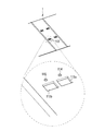
例えば、図6に示すように、背表紙側貫通孔113を非拡張状態用の貫通孔113aと、拡張状態用の貫通孔113bに分けてもよい。この場合、非拡張状態から拡張状態への移行、又は、拡張状態から非拡張状態への移行をするに際しては、固定装置4を分離する必要が生じる。しかし、各状態をより強固に維持することが可能となる。また、貫通孔113a及び貫通孔113bの背幅方向の幅を内側起立片45a、外側起立片45bの距離よりも広く設定すれば、さらに、上記実施形態と同様の効果(最大綴じ量を僅かに増やしたいという要求に応える効果)も奏する。すなわち貫通部である綴じ具側貫通孔及び孔部である背表紙側貫通孔の少なくとも一方が複数設けられており、固定装置が貫通する貫通部及び係合する孔部によって第一基板部と第二基板部の背幅方向における相対的な距離が決定されるように構成してもよい。
For example, as shown in FIG. 6, the spine side through-
係止突部46に対応する係止孔を3つ以上設ければ、綴じ具2において安定的に維持される最大綴じ量をより多くすることができ、背幅の最適化等に寄与する。
上記ファイル100は、第一基板部21及び第二基板部31ともに可動基板部としたが、少なくとも一方が可動基板部であればよい。
固定装置4による固定方法も上記に限定されるものではなく、上記機構に耐えうる綴じ具の基板部を表紙体1に固定する方法(機構)であればよい。
固定装置4を軸部42の両端部に頭部を有するリベット等によって構成してもよい。その結果、より簡易な構成のファイルを提供することが可能となる。
If three or more locking holes corresponding to the locking
In the
The fixing method by the fixing device 4 is not limited to the above, and any method (mechanism) may be used as long as the substrate portion of the binding tool that can withstand the mechanism is fixed to the
The fixing device 4 may be configured by rivets having heads at both ends of the
非拡張状態と拡張状態とのスライド移動をガイドするガイド機構を設けてもよい。例えば、図4等に示すように、第一基板部側貫通孔211の長手方向の両縁部に、第一基板部21の裏面側(背表紙11との接触側)に突出したガイド爪212を設け、ガイド爪212が背表紙側貫通孔113の端部と係りあうことでガイド機構を構成することもできる。
当然下記構成も採用し得る。
A guide mechanism for guiding the sliding movement between the non-expanded state and the expanded state may be provided. For example, as shown in FIG. 4 and the like, the
Of course, the following configuration may also be adopted.
背表紙、背表紙の背幅方向の両端部に各々接続された表表紙及び裏表紙とを有する表紙体と、綴じ具と、を備えたファイルである。綴じ具は、背表紙に当接する第一基板部及び第二基板部と、第一基板部に設けられた第一串部及び第二基板部に設けられた第二串部と、を備えている。第一基板部及び第二基板部の少なくとも一方は、他方の基板部に対して背表紙の背幅方向へ相対的に移動可能な可動基板部とされ、第一串部及び第二串部は、第一基板部及び第二基板部の背幅方向への相対的な移動に対応し、両者の間隔がいずれであっても係りあって紙葉類を綴込可能な綴じ量変更機能を備えている。可動基板部は貫通部を備え、背表紙における貫通部に対応する位置には孔部が設けられ、固定装置は、貫通部を貫通した状態で背表紙における孔部周辺並びに前記基板部における貫通部周辺と係合して可動基板部が背表紙から離れない状態に保つ。そして、貫通部の背幅方向の幅は孔部の幅よりも狭い。 The file includes a back cover, a cover body having a front cover and a back cover respectively connected to both ends in the spine width direction of the spine cover, and a binding tool. The binding tool includes a first substrate portion and a second substrate portion that contact the spine, and a first skewer portion provided on the first substrate portion and a second skewer portion provided on the second substrate portion. Yes. At least one of the first substrate portion and the second substrate portion is a movable substrate portion that can move relative to the other substrate portion in the spine width direction, and the first skewer portion and the second skewer portion are Corresponding to the relative movement of the first substrate portion and the second substrate portion in the spine width direction, it has a binding amount changing function capable of binding paper sheets regardless of the distance between them. ing. The movable substrate portion includes a through portion, and a hole portion is provided at a position corresponding to the through portion in the spine. The fixing device penetrates the through portion, and the periphery of the hole portion in the spine and the through portion in the substrate portion. Engage with the periphery to keep the movable substrate part away from the spine. And the width | variety of the back width direction of a penetration part is narrower than the width | variety of a hole.
このファイルは、さらに、固定装置の可動基板部に対する背幅方向の移動を制限する第一の制限手段を備えていることが好ましい。第一の制限手段は、上記実施形態の構成以外にも、例えば固定装置と可動基板部とを直接係合するといった構成も採用し得る。 This file preferably further includes first limiting means for limiting movement in the spine width direction with respect to the movable substrate portion of the fixing device. In addition to the configuration of the above-described embodiment, for example, a configuration in which the fixing device and the movable substrate unit are directly engaged can be adopted as the first limiting unit.
上記ファイルにおいて、貫通部の背幅方向の幅を孔部の幅よりも広くしても、上記同等の作用・効果を奏する。この場合、第一の制限手段に代えて、固定装置の背表紙に対する背幅方向の移動を制限する第二の制限手段を設けるとよい。 In the above file, even if the width in the back width direction of the penetrating portion is made wider than the width of the hole portion, the same operation and effect are obtained. In this case, instead of the first limiting means, it is preferable to provide second limiting means for limiting the movement of the fixing device in the spine width direction with respect to the spine.
上記ファイルには、さらに、可動基板部の背表紙における背幅方向の位置を任意の位置で固定する位置調整手段が好適に設けられる。 The file is further preferably provided with position adjusting means for fixing the position in the spine width direction on the spine of the movable substrate portion at an arbitrary position.
また、上記ファイルにおいて、貫通部の背幅方向の幅と孔部の背幅方向の幅を略同一とし、固定装置における貫通部内に配置される部位の背幅方向の幅は貫通部の背幅方向の幅よりも狭く、固定装置における孔部内に配置される部位の背幅方向の幅は貫通部の背幅方向の幅よりも狭くしても、上記同等の作用・効果を奏する。このように構成する場合であっても、制限手段や位置調整手段が好適に設けられる。 Further, in the above file, the width in the back width direction of the through portion and the width in the back width direction of the hole portion are substantially the same, and the width in the back width direction of the portion disposed in the through portion in the fixing device is Even if the width in the back width direction of the portion arranged in the hole portion in the fixing device is narrower than the width in the direction, the same effect and effect as described above can be obtained. Even in such a configuration, the limiting means and the position adjusting means are preferably provided.
上記したようなファイルにおいては、表表紙及び背表紙の内、背表紙の背幅方向に対する中心線を基準として可動基板部が存する側の表紙は、背表紙との間に複数本のヒンジを介して接続するように構成される。これにより、表紙体を一枚構成で構成しても、背幅・最大綴じ量を変化させることができる。 In the file as described above, the cover on the side where the movable substrate portion exists with respect to the center line with respect to the spine width direction of the back cover and the back cover, with a plurality of hinges between the back cover and the back cover. Configured to connect. As a result, the back width and the maximum binding amount can be changed even if the cover body is constituted by one sheet.
背表紙と、該背表紙の背幅方向の両端部に夫々接続される表表紙と裏表紙とを有する表紙体と、紙葉類を綴じる綴じ具であって、前記表紙体の背表紙に取り付けられる第一基板部と、該背表紙の背幅方向に該第一基板部と略並行に取り付けられる第二基板部とを有し、該第一基板部と該第二基板部とのうちの少なくとも一方が、前記背表紙の背幅方向へ、該背表紙に対して移動可能な綴じ具と、前記第一基板部と前記第二基板部とのうち少なくとも一方を、前記背表紙の背幅方向へ移動可能に固定する固定部と、を備えたファイル。このファイルでは、綴じ具を構成する第一基板部と第二基板部のうち少なくとも一方が、背表紙の背幅方向へ移動することで、綴じ量の調整が可能となる。また、二つの重ねられた背表紙を相対的に移動させることで綴じ量を調整する従来のファイルでは、別部品とし
て構成される表表紙と裏表紙の夫々に背幅調整部が設けられ、さらに、表表紙と裏表紙との分解を防止するためのロック手段、及びロック手段を操作するための操作手段が必要であった。これに対し、このファイルでは、第一基板部又は第二基板部が背表紙に対して移動できればよく、表紙体を可動させる必要がない。従って、背表紙の構成を単純化することができる。また、そもそも表表紙と裏表紙との分解を防止するためのロック手段やこれを操作するための操作手段といった構成が不要となる。つまり、従来よりも少ない部品点数、かつ単純な構成で綴じ量を調整可能なファイルを提供することができる。また、表紙体の背表紙が重なることもないので、背表紙の厚さを一般的なファイルと同様にすることができ、また、背表紙が重なる従来技術と比較すると、表紙体の材料を少なくすることができる。
A cover body having a spine cover, a front cover and a back cover respectively connected to both ends in the spine width direction of the spine cover, and a binding tool for binding paper sheets, and attached to the spine cover of the cover body A first substrate portion, and a second substrate portion attached substantially parallel to the first substrate portion in the spine width direction of the spine cover, and the first substrate portion and the second substrate portion, At least one of the binding tool that is movable relative to the spine in the spine width direction of the spine cover, and at least one of the first substrate portion and the second substrate portion, the spine width of the spine cover A file having a fixing portion that is fixed to be movable in a direction. In this file, the binding amount can be adjusted by moving at least one of the first substrate portion and the second substrate portion constituting the binding tool in the spine width direction of the spine. Further, in a conventional file that adjusts the binding amount by relatively moving two stacked spine covers, a spine width adjustment unit is provided on each of the front cover and the back cover configured as separate parts. Therefore, a lock unit for preventing the front cover and the back cover from being disassembled and an operation unit for operating the lock unit are required. On the other hand, in this file, it is only necessary that the first substrate portion or the second substrate portion can move with respect to the back cover, and it is not necessary to move the cover body. Accordingly, the configuration of the spine can be simplified. Also, it is not necessary to have a configuration such as a lock unit for preventing the front cover and the back cover from being disassembled and an operation unit for operating the cover. That is, it is possible to provide a file in which the binding amount can be adjusted with a simpler configuration with a smaller number of parts than before. In addition, since the back cover of the cover body does not overlap, the thickness of the back cover can be made the same as that of a general file, and the material of the cover body is reduced compared to the conventional technology where the back cover overlaps. can do.
上記ファイルでは、綴じ具を構成する基板部が二つの部材(第一基板部と第二基板部)によって構成され、この二つの基板部同士の間隔を調整することで、綴じ量を調整することができる。第一基板部と第二基板部は、表紙本体の背表紙に固定部材によって移動可能に取り付けられることから、第一基板部と第二基板部は、少なくとも背表紙の背幅内での移動が可能である。 In the above file, the substrate part constituting the binding tool is composed of two members (first substrate part and second substrate part), and the binding amount is adjusted by adjusting the distance between the two substrate parts. Can do. Since the first substrate portion and the second substrate portion are movably attached to the spine cover of the cover body by a fixing member, the first substrate portion and the second substrate portion can move at least within the spine width of the spine cover. Is possible.
上述したように、このファイルは、綴じ具の基板部が移動することで、綴じ具の状態が変化することを特徴とする。そこで、このような綴じ具の状態変化を踏まえ、この綴じ具は、以下のようにしてもよい。すなわち、前記綴じ具は、前記第一基板部と前記第二基板部との間隔が最も狭い非拡張状態と、前記第一基板部と前記第二基板部との間隔が前記背表紙の背幅内において拡張する拡張状態とを形成する。 As described above, this file is characterized in that the state of the binding tool changes as the substrate portion of the binding tool moves. Therefore, in consideration of the state change of the binding tool, the binding tool may be configured as follows. That is, the binding tool has a non-expanded state in which the distance between the first substrate portion and the second substrate portion is the narrowest, and the distance between the first substrate portion and the second substrate portion is the spine width of the spine. And an expanded state that expands within.
拡張状態では、非拡張状態と比較して第一基板部と第二基板部との間隔が広がる。そこで、このファイルを設計するに際しては、上記拡張状態において第一基板部と第二基板部が背表紙の背幅内に収まるように設計すればよい。なお、非拡張状態から拡張状態への変更、又は、拡張状態から非拡張状態への変更は、使用者が、第一基板部又は第二基板部を把持して適宜調整すればよい。但し、拡張状態から非拡張状態への変更は、表表紙又は裏表紙を介して与えられる外部からの力を利用することもできる。具体的には、非拡張状態で使用できるにもかかわらず拡張状態で戸棚に収容した場合には、隣接する他のファイルに挟まれ、側面から力が働くことで自然に非拡張状態へ変更される。また、綴じ量が多く非拡張状態への変更は無理な場合であっても、戸棚に収容した時点の拡張状態において綴じ量の余裕がある場合には、隣接するファイルによる力によって綴じ量に合った拡張状態へ変更される。 In the expanded state, the distance between the first substrate portion and the second substrate portion is wider than in the non-expanded state. Therefore, when designing this file, the first substrate portion and the second substrate portion may be designed to fit within the spine width of the spine cover in the expanded state. Note that the change from the non-expanded state to the expanded state, or the change from the expanded state to the non-expanded state may be performed by the user appropriately holding the first substrate portion or the second substrate portion. However, the change from the expanded state to the non-expanded state can use an external force applied via the front cover or the back cover. Specifically, when it can be used in the non-expanded state but is stored in the cupboard in the expanded state, it is sandwiched between other adjacent files and is naturally changed to the non-expanded state by applying force from the side. The Even if the amount of binding is large and it is impossible to change to the non-expanded state, if there is a margin for the amount of binding in the expanded state at the time when it is stored in the cupboard, it will match the binding amount by the force of the adjacent file. Changed to the expanded state.
ここで、このファイルでは、前記表表紙と前記裏表紙とのうち少なくとも一方は、前記表紙体を開閉する際に開閉軸となるヒンジであって、前記背表紙の背幅方向の端部に該背幅方向へ段階的に設けられた複数のヒンジを介して該背表紙と接続され、前記表紙体は、前記開閉軸として機能するヒンジが前記複数のヒンジから綴じ量に応じて切り替えられることで、前記背表紙の背幅が段階的に調整できるようにしてもよい。 Here, in this file, at least one of the front cover and the back cover is a hinge serving as an opening and closing shaft when the cover body is opened and closed, and is provided at the end of the spine cover in the spine width direction. The back cover is connected to the spine through a plurality of hinges provided in a stepwise manner in the spine width direction, and the cover is switched from the plurality of hinges according to the binding amount from the plurality of hinges. The back width of the spine may be adjusted stepwise.
このファイルによれば、複数のヒンジの中から開閉軸として機能するヒンジが切り替えられることで、背表紙の背幅を調整することができる。ヒンジは、例えば、薄肉ヒンジとすることができる。なお、ヒンジの数は、特に限定されず、外側のヒンジを用いるにつれて、背幅を徐々に拡張することができる。但し、このファイルでは、外側のヒンジを用いた場合、本来、表表紙又は裏表紙であった領域を背表紙として用いることで、背幅の拡張を実現している。従って、ヒンジの数を設計するに際しては、表表紙又は裏表紙の横幅を考慮することが好ましい。 According to this file, the back width of the spine can be adjusted by switching the hinge functioning as an opening / closing axis from among a plurality of hinges. The hinge can be, for example, a thin hinge. The number of hinges is not particularly limited, and the back width can be gradually expanded as the outer hinge is used. However, in this file, when the outer hinge is used, the extension of the spine width is realized by using the area that was originally the front cover or the back cover as the back cover. Therefore, when designing the number of hinges, it is preferable to consider the width of the front cover or the back cover.
ヒンジの切り替えは、綴じ量、換言すると第一基板部と第二基板部との間隔に応じて行
われる。例えば、綴じ量が少ない場合には、背幅方向の内側のヒンジが機能し、綴じ量が多い場合には、背幅方向の外側のヒンジが機能する。ヒンジの切り替えは、使用者が行ってもよいが、ヒンジを薄肉ヒンジによって構成すれば、特に使用者が変更しなくても綴じ量に応じて切り替えられる。
The switching of the hinge is performed according to the binding amount, in other words, according to the interval between the first substrate portion and the second substrate portion. For example, when the binding amount is small, the inner hinge in the spine width direction functions, and when the binding amount is large, the outer hinge in the spine width direction functions. The hinge may be switched by the user. However, if the hinge is formed of a thin hinge, the hinge can be switched according to the binding amount without any change by the user.
また、このファイルは、前記第一基板部と前記第二基板部とのうち、前記固定部によって移動可能に固定される基板部の移動を規制する規制部をさらに備える構成としてもよい。 Moreover, this file is good also as a structure further provided with the control part which controls the movement of the board | substrate part fixed so that a movement is possible by the said fixing | fixed part among said 1st board | substrate part and said 2nd board | substrate part.
規制部を備えることで、基板部の移動を規制することができる。換言すると、規制部によって、非拡張状態から拡張状態への変更、拡張状態から非拡張状態への変更を規制することができる。 By providing the restricting portion, the movement of the substrate portion can be restricted. In other words, the restriction unit can restrict the change from the non-expanded state to the expanded state and the change from the expanded state to the non-expanded state.
なお、このファイルにおける綴じ具は、紙葉類の綴じ孔に綴り管を挿入するパイプ式綴じ具によって構成することができる。一方、このファイルは、綴じ具を構成する第一基板部と第二基板部との間隔を調整することで、綴じ量を調整することが可能である。従って、パイプ式綴じ具とした場合には、基板部の間隔に応じてパイプの長さも調整できることが好ましい。また、例えば、パイプの内部に綴り棒を挿入する構成とする場合には、綴じ具の拡張によってパイプの長さが不足することが想定される。綴り棒がパイプに内包されており、内包されていた綴り棒が拡張によって露出するので、拡張した場合でも、紙葉類が脱落することはない。但し、パイプが不足した分部では、紙葉類がパイプより外径が小さい綴り棒によって保持され、綴り管ががたつくことが懸念される。 Note that the binding tool in this file can be configured by a pipe-type binding tool that inserts a binding tube into a binding hole of a paper sheet. On the other hand, this file can adjust the amount of binding by adjusting the distance between the first substrate portion and the second substrate portion constituting the binding tool. Therefore, in the case of a pipe-type binding tool, it is preferable that the length of the pipe can be adjusted according to the distance between the substrate portions. In addition, for example, in the case where a binding rod is inserted into the pipe, it is assumed that the length of the pipe is insufficient due to the expansion of the binding tool. Since the spelling rod is contained in the pipe and the contained spelling rod is exposed by the expansion, the paper sheets do not fall off even when expanded. However, in the part where the pipe is insufficient, there is a concern that the paper sheet is held by a spelling rod having an outer diameter smaller than that of the pipe, and the spelling tube is rattled.
そこで、このような問題を解決するため、このファイルは、前記綴じ具は、前記第一基板部と前記第二基板部とに着脱可能に接続され、紙葉類の綴じ孔に挿入されるパイプを有する綴り部をさらに有し、前記綴じ具は、前記第一基板部と前記第二基板部との間隔が最も狭い非拡張状態と、前記第一基板部と前記第二基板部との間隔が前記背表紙の背幅内において拡張する拡張状態を形成し、該拡張状態において前記パイプの先端へ接続される補助パイプを有する構成としてもよい。 Therefore, in order to solve such a problem, this file is a pipe in which the binding tool is detachably connected to the first substrate portion and the second substrate portion, and is inserted into a binding hole of a paper sheet. The binding tool further includes an unextended state in which the interval between the first substrate portion and the second substrate portion is the smallest, and the interval between the first substrate portion and the second substrate portion. It is good also as a structure which has the expansion state which expands within the spine width of the spine, and has an auxiliary pipe connected to the tip of the pipe in the expansion state.
このファイルによれば、補助パイプを備えることで、綴り管のがたつきを防止することができる。また、補助パイプをパイプの先端へ接続することで、拡張状態から非拡張状態への変更を規制することもできる。 According to this file, it is possible to prevent rattling of the spell tube by providing the auxiliary pipe. Moreover, the change from the expanded state to the non-expanded state can be restricted by connecting the auxiliary pipe to the tip of the pipe.
なお、補助パイプは、綴じ具が拡張状態の場合にのみ使用する。そこで、未使用時の補助パイプの紛失を防止するため、例えば、固定部に、補助パイプを収容する補助パイプ収容部を設けてもよい。これにより、非拡張状態において補助パイプを収容することができ、補助パイプの紛失を防止することができる。なお、補助パイプ収容部は、固定部に限らず、例えば、表紙体の一部に設けるようにしてもよい。 The auxiliary pipe is used only when the binding tool is in the expanded state. Therefore, in order to prevent the loss of the auxiliary pipe when not in use, for example, an auxiliary pipe accommodating portion that accommodates the auxiliary pipe may be provided in the fixing portion. Thereby, an auxiliary pipe can be accommodated in a non-expanded state, and loss of the auxiliary pipe can be prevented. Note that the auxiliary pipe housing portion is not limited to the fixed portion, and may be provided, for example, in a part of the cover body.
ここで、上述したこのファイルは、各構成をより具体化し、以下のようにしてもよい。具体的には、前記固定部は、前記背表紙を押さえる表紙押さえ部と、前記第一基板部と前記第二基板部とのうち少なくとも移動する基板部を押さえる綴じ具押さえ部と、前記表紙押さえ部と前記綴じ具押さえ部とが接続される軸部とを有する構成とすることができる。なお、表紙押さえ部と軸部とを一体的に構成し、このように一体的に構成された表紙押さえ部と軸部に対して、綴じ具押さえ部を分離可能に構成してもよい。固定部を上記のように分離可能な構成とすることで、表紙体と綴じ具との分離を容易に行うことが可能となる。なお、表紙押さえ部が背表紙を押さえる力や、綴じ具押さえ部が移動基板部を押さえる力は、固定部が表紙体及び綴じ具の基板部を挟み込んだ際に、基板部が移動できるように設定すればよい。具体的には、軸部の長さを調節することで、適宜設計することができる
。
Here, this file described above may be more specific in each configuration and may be as follows. Specifically, the fixing portion includes a cover pressing portion that presses the spine, a binding tool pressing portion that presses at least the moving substrate portion of the first substrate portion and the second substrate portion, and the cover pressing portion. And a shaft portion to which the binding tool pressing portion is connected. Note that the cover pressing portion and the shaft portion may be configured integrally, and the binding tool pressing portion may be configured to be separable from the cover pressing portion and the shaft portion configured in this manner. By making the fixing portion separable as described above, the cover body and the binding tool can be easily separated. Note that the force that the cover holding part holds the back cover and the force that the binding tool holding part holds the moving board part is so that the board part can move when the fixing part sandwiches the cover body and the board part of the binding tool. You only have to set it. Specifically, it can be designed as appropriate by adjusting the length of the shaft portion.
また、前記第一基板部と前記第二基板部とのうち少なくとも移動する基板部は、前記固定部の軸部が貫通する綴じ具側貫通孔を有する構成としてもよい。また、前記背表紙は、前記固定部の軸部が貫通する背表紙側貫通孔であって、該軸部の前記背幅方向への移動を許容する背表紙側貫通孔を前記綴じ具側貫通孔と略対応する位置に有する構成としてもよい。基板部に綴じ具側貫通孔を設け、背表紙に背表紙側貫通項を設け、これら二つの貫通孔に上述した固定部の軸部を貫通させることで簡易な構成で移動する基板部を背表紙に固定することができる。また、綴じ具側貫通孔は、その大きさが、固定部の軸部が背幅方向への移動を許容するように背表紙側貫通孔よりも大きく形成されている。従って、固定部の軸部は、綴じ具側貫通孔内を移動し、これに伴って固定部の綴じ具押さえ部によって押さえられている第一基板部又は第二基板部が移動する。つまり、前記第一基板部と前記第二基板部とのうち少なくとも一方の基板部が、前記軸部が背幅方向への移動を許容される範囲内で移動する。 Moreover, the board | substrate part which moves at least among the said 1st board | substrate part and said 2nd board | substrate part is good also as a structure which has a binding tool side through-hole which the axial part of the said fixing | fixed part penetrates. The spine is a spine-side through-hole through which the shaft portion of the fixed portion passes, and the binding-tool-side through-hole is permitted to allow the shaft portion to move in the spine width direction. It is good also as a structure which has in the position substantially corresponding to a hole. The substrate part is provided with a binding tool side through hole, the spine cover is provided with a back cover side through term, and the shaft part of the fixed part described above is passed through these two through holes, so that the substrate part that moves with a simple configuration can be connected to the back part. Can be fixed on the cover. Further, the binding tool side through hole is formed to be larger in size than the spine cover side through hole so that the shaft portion of the fixed portion allows movement in the spine width direction. Therefore, the shaft portion of the fixing portion moves in the binding tool side through hole, and accordingly, the first substrate portion or the second substrate portion pressed by the binding tool pressing portion of the fixing portion moves. That is, at least one of the first substrate portion and the second substrate portion moves within a range in which the shaft portion is allowed to move in the spine width direction.
ここで、このファイルにおいて、前記背表紙側貫通孔は、前記背表紙の背幅方向へ複数設けられるようにしてもよい。これにより、背表紙側貫通孔を適宜選択することで綴じ量、すなわち第一基板部と第二基板部との間隔を調整することが可能となる。また、このファイルでは、夫々の背表紙側貫通孔が軸部の移動を許容するように設計されている。従って、背表紙側貫通孔の選択により大まかな綴じ量を設定することができ、選択された背表紙側貫通孔内で軸部を移動させることで綴じ量の細かい調整が可能となる。 Here, in this file, a plurality of the spine side through holes may be provided in the spine width direction of the spine cover. Accordingly, it is possible to adjust the binding amount, that is, the interval between the first substrate portion and the second substrate portion by appropriately selecting the spine side through-hole. Also, in this file, each spine side through-hole is designed to allow the shaft portion to move. Accordingly, a rough binding amount can be set by selecting the spine side through-hole, and the binding amount can be finely adjusted by moving the shaft portion in the selected spine side through-hole.
なお、例えば、背表紙側貫通孔を背幅方向へ複数設け、第一基板部と第二基板部とのうち少なくとも一方の基板部は、前記軸部が背幅方向への移動を許容される範囲内で移動するようにしてもよい。このファイルによれば、背表紙側貫通孔を適宜選択することで綴じ量、すなわち第一基板部と第二基板部との間隔を調整することが可能となる。また、選択された背表紙側貫通孔内において軸部は、移動しないので、第一基板部と第二基板部との間隔を固定することができる。 In addition, for example, a plurality of spine-side through-holes are provided in the spine width direction, and at least one of the first substrate portion and the second substrate portion is allowed to move in the spine width direction of the shaft portion. You may make it move within the range. According to this file, it is possible to adjust the binding amount, that is, the distance between the first substrate portion and the second substrate portion by appropriately selecting the spine side through hole. Further, since the shaft portion does not move within the selected spine side through-hole, the distance between the first substrate portion and the second substrate portion can be fixed.
1:表紙体、2:綴じ具、4:固定装置、11:裏表紙、12:表表紙、13:裏表紙、21:第一基板部、25:綴り棒、31:第二基板部、35:パイプ、40:ベース部材、50:スライド部材、54:補助パイプ収容部、61:補助パイプ、100:ファイル、111:内側薄肉ヒンジ、112:外側薄肉ヒンジ、113:背表紙側貫通孔、114:内側係止孔、115:外側係止孔 1: front cover body, 2: binding tool, 4: fixing device, 11: back cover, 12: front cover, 13: back cover, 21: first substrate portion, 25: binding rod, 31: second substrate portion, 35 : Pipe, 40: Base member, 50: Slide member, 54: Auxiliary pipe accommodating portion, 61: Auxiliary pipe, 100: File, 111: Inner thin hinge, 112: Outer thin hinge, 113: Back cover side through hole, 114 : Inner locking hole, 115: outer locking hole
Claims (9)
紙葉類を綴じる綴具であって、前記表紙体の背表紙に取り付けられる第一基板部と、該背表紙の背幅方向に該第一基板部と略並行に取り付けられる第二基板部とを有し、該第一基板部と該第二基板部とのうちの少なくとも一方が、前記背表紙の背幅方向へ、該背表紙に対して移動可能な綴具と、
前記第一基板部と前記第二基板部とのうち少なくとも一方を、前記背表紙の背幅方向へ移動可能に固定する固定部と、を備えるファイル。 A cover body having a back cover and a front cover and a back cover respectively connected to both ends in the spine width direction of the spine;
A binding device for binding paper sheets, a first substrate portion attached to a spine cover of the cover body, and a second substrate portion attached substantially parallel to the first substrate portion in the spine width direction of the spine cover A binding device in which at least one of the first substrate portion and the second substrate portion is movable relative to the spine in the spine width direction of the spine;
A file comprising: a fixing portion that fixes at least one of the first substrate portion and the second substrate portion so as to be movable in a spine width direction of the spine cover.
前記表紙体は、前記開閉軸として機能するヒンジが前記複数のヒンジから綴じ量に応じて切り替えられることで、前記背表紙の背幅が段階的に調整できる、請求項1又は請求項2に記載のファイル。 At least one of the front cover and the back cover is a hinge serving as an opening and closing shaft when the cover body is opened and closed, and is stepwise in the spine width direction at an end portion of the spine cover in the spine width direction. Connected to the spine through a plurality of hinges provided,
The back cover can be adjusted stepwise by adjusting the back width of the spine in a stepwise manner by switching a hinge functioning as the opening and closing shaft from the plurality of hinges according to a binding amount. Files.
前記綴具は、前記第一基板部と前記第二基板部との間隔が最も狭い非拡張状態と、前記第一基板部と前記第二基板部との間隔が前記背表紙の背幅内において拡張する拡張状態を形成し、該拡張状態において前記パイプの先端へ接続される補助パイプを有する、請求項1、請求項3、又は請求項4に記載のファイル。 The binding device further includes a binding portion that is detachably connected to the first substrate portion and the second substrate portion and has a pipe that is inserted into a binding hole of a paper sheet,
In the binding tool, the non-expanded state in which the distance between the first substrate portion and the second substrate portion is the narrowest, and the interval between the first substrate portion and the second substrate portion is within the spine width of the spine cover. The file according to claim 1, 3 or 4, comprising an auxiliary pipe that forms an expanded state that expands and is connected to a tip of the pipe in the expanded state.
前記第一基板部と前記第二基板部とのうち少なくとも移動する基板部は、前記固定部の軸部が貫通する綴具側貫通孔を有し、
前記背表紙は、前記固定部の軸部が貫通する背表紙側貫通孔であって、該軸部の前記背幅方向への移動を許容する背表紙側貫通孔を前記綴具側貫通孔と略対応する位置に有し、
前記第一基板部と前記第二基板部とのうち少なくとも一方の基板部は、前記軸部が背幅方向への移動を許容される範囲内で移動する、請求項1から請求項6のいずれか一に記載のファイル。 The fixing portion includes a cover pressing portion that presses the spine, a binding pressing portion that presses at least the moving substrate portion of the first substrate portion and the second substrate portion, the cover pressing portion, and the binding tool. A shaft portion to which the holding portion is connected,
The substrate portion that moves at least between the first substrate portion and the second substrate portion has a binding tool side through-hole through which the shaft portion of the fixing portion passes,
The spine is a spine cover side through-hole through which the shaft portion of the fixed portion passes, and the spine cover side through hole that allows the shaft portion to move in the spine width direction is the binding device side through hole. In approximately corresponding positions,
7. The method according to claim 1, wherein at least one of the first substrate portion and the second substrate portion moves within a range in which the shaft portion is allowed to move in the spine width direction. The file described in Kaichi.
前記第一基板部と前記第二基板部とのうち少なくとも移動する基板部は、前記固定部の軸部が貫通する綴具側貫通孔を有し、
前記背表紙は、前記固定部の軸部が貫通する背表紙側貫通孔を、前記背幅方向において複数有し、
前記第一基板部と前記第二基板部とのうち少なくとも一方の基板部は、前記軸部が背幅方向への移動を許容される範囲内で移動する、請求項1から請求項3、請求項5、又は請求項6のいずれか一に記載のファイル。 The fixing portion includes a cover pressing portion that presses the spine, a binding pressing portion that presses at least the moving substrate portion of the first substrate portion and the second substrate portion, the cover pressing portion, and the binding tool. A shaft portion to which the holding portion is connected,
The substrate portion that moves at least between the first substrate portion and the second substrate portion has a binding tool side through-hole through which the shaft portion of the fixing portion passes,
The spine cover has a plurality of spine side through-holes through which the shaft portion of the fixed part penetrates in the spine width direction,
The at least one of the first substrate portion and the second substrate portion moves within a range in which the shaft portion is allowed to move in the spine width direction. Item 7. The file according to any one of item 5 or item 6.
Priority Applications (1)
| Application Number | Priority Date | Filing Date | Title |
|---|---|---|---|
| JP2008215511A JP5149102B2 (en) | 2008-08-25 | 2008-08-25 | File |
Applications Claiming Priority (1)
| Application Number | Priority Date | Filing Date | Title |
|---|---|---|---|
| JP2008215511A JP5149102B2 (en) | 2008-08-25 | 2008-08-25 | File |
Publications (2)
| Publication Number | Publication Date |
|---|---|
| JP2010046987A true JP2010046987A (en) | 2010-03-04 |
| JP5149102B2 JP5149102B2 (en) | 2013-02-20 |
Family
ID=42064487
Family Applications (1)
| Application Number | Title | Priority Date | Filing Date |
|---|---|---|---|
| JP2008215511A Active JP5149102B2 (en) | 2008-08-25 | 2008-08-25 | File |
Country Status (1)
| Country | Link |
|---|---|
| JP (1) | JP5149102B2 (en) |
Cited By (5)
| Publication number | Priority date | Publication date | Assignee | Title |
|---|---|---|---|---|
| CN102275411A (en) * | 2010-06-01 | 2011-12-14 | 株式会社锦宫事务 | Tubular binder |
| JP2012240335A (en) * | 2011-05-20 | 2012-12-10 | King Jim Co Ltd | Binder |
| WO2016178364A1 (en) * | 2015-05-01 | 2016-11-10 | 株式会社キングジム | Anchoring structure for binding implement and cover, and binder |
| JP2016210053A (en) * | 2015-05-01 | 2016-12-15 | 株式会社キングジム | Fixation structure of binding tool and cover sheet, and file |
| JP2017030203A (en) * | 2015-07-30 | 2017-02-09 | 株式会社キングジム | Fixation structure of binding tool and cover sheet, and file |
Citations (6)
| Publication number | Priority date | Publication date | Assignee | Title |
|---|---|---|---|---|
| JPS52110517U (en) * | 1976-02-16 | 1977-08-23 | ||
| JPS63156785U (en) * | 1987-03-31 | 1988-10-14 | ||
| JP2007320159A (en) * | 2006-05-31 | 2007-12-13 | King Jim Co Ltd | Binder and filing implement equipped therewith |
| JP2008044157A (en) * | 2006-08-11 | 2008-02-28 | Kokuyo Co Ltd | Binding implement, extension pipe and file |
| JP2008044156A (en) * | 2006-08-11 | 2008-02-28 | Kokuyo Co Ltd | File |
| JP2008207448A (en) * | 2007-02-26 | 2008-09-11 | Kokuyo Co Ltd | File |
-
2008
- 2008-08-25 JP JP2008215511A patent/JP5149102B2/en active Active
Patent Citations (6)
| Publication number | Priority date | Publication date | Assignee | Title |
|---|---|---|---|---|
| JPS52110517U (en) * | 1976-02-16 | 1977-08-23 | ||
| JPS63156785U (en) * | 1987-03-31 | 1988-10-14 | ||
| JP2007320159A (en) * | 2006-05-31 | 2007-12-13 | King Jim Co Ltd | Binder and filing implement equipped therewith |
| JP2008044157A (en) * | 2006-08-11 | 2008-02-28 | Kokuyo Co Ltd | Binding implement, extension pipe and file |
| JP2008044156A (en) * | 2006-08-11 | 2008-02-28 | Kokuyo Co Ltd | File |
| JP2008207448A (en) * | 2007-02-26 | 2008-09-11 | Kokuyo Co Ltd | File |
Cited By (7)
| Publication number | Priority date | Publication date | Assignee | Title |
|---|---|---|---|---|
| CN102275411A (en) * | 2010-06-01 | 2011-12-14 | 株式会社锦宫事务 | Tubular binder |
| JP2012240335A (en) * | 2011-05-20 | 2012-12-10 | King Jim Co Ltd | Binder |
| WO2016178364A1 (en) * | 2015-05-01 | 2016-11-10 | 株式会社キングジム | Anchoring structure for binding implement and cover, and binder |
| JP2016210053A (en) * | 2015-05-01 | 2016-12-15 | 株式会社キングジム | Fixation structure of binding tool and cover sheet, and file |
| CN107531083A (en) * | 2015-05-01 | 2018-01-02 | 株式会社锦宫事务 | The fixture construction and file of binding parts and strip of paper used for sealing |
| CN107531083B (en) * | 2015-05-01 | 2019-07-05 | 株式会社锦宫事务 | The fixture construction and file of binding parts and strip of paper used for sealing |
| JP2017030203A (en) * | 2015-07-30 | 2017-02-09 | 株式会社キングジム | Fixation structure of binding tool and cover sheet, and file |
Also Published As
| Publication number | Publication date |
|---|---|
| JP5149102B2 (en) | 2013-02-20 |
Similar Documents
| Publication | Publication Date | Title |
|---|---|---|
| JP5149102B2 (en) | File | |
| US7524127B2 (en) | Ring binder mechanism | |
| JP4909645B2 (en) | Binding tool | |
| WO2007070179A2 (en) | Ring binder mechanism | |
| JP4534088B2 (en) | Binding tools and files | |
| JP5973154B2 (en) | Binder lock assist device | |
| JP4804265B2 (en) | File | |
| JP4132903B2 (en) | Binding tools and files | |
| JP2009248569A (en) | Book using binder rings | |
| JP2005132065A (en) | File and cover body | |
| WO2009123219A1 (en) | Loose leaf binding fixture attachment device, cover, and loose leaf binding fixture affixing method | |
| JP4023551B2 (en) | Folder file | |
| JP5043181B2 (en) | Binding device fixing device, file and binding device fixing mechanism | |
| JP4168994B2 (en) | Binding foot holding structure and file | |
| JP6558944B2 (en) | Fixing structure of binding tool and cover, and file | |
| JP2007007913A (en) | File, binder and manually operating member | |
| JP2007245455A (en) | Binding implement and filing implement equipped with it | |
| JP6484104B2 (en) | Fixing structure of binding tool and cover, and file | |
| KR200235215Y1 (en) | Binder Attachment | |
| JP4028585B1 (en) | Punching equipment | |
| JP3421919B2 (en) | File | |
| JP6475587B2 (en) | Fixing structure of binding tool and cover, and file | |
| JP5138454B2 (en) | Back width adjustment file | |
| WO2016178364A1 (en) | Anchoring structure for binding implement and cover, and binder | |
| JPS6347500Y2 (en) |
Legal Events
| Date | Code | Title | Description |
|---|---|---|---|
| A621 | Written request for application examination |
Free format text: JAPANESE INTERMEDIATE CODE: A621 Effective date: 20110117 |
|
| A977 | Report on retrieval |
Free format text: JAPANESE INTERMEDIATE CODE: A971007 Effective date: 20120828 |
|
| A131 | Notification of reasons for refusal |
Free format text: JAPANESE INTERMEDIATE CODE: A131 Effective date: 20120904 |
|
| A521 | Request for written amendment filed |
Free format text: JAPANESE INTERMEDIATE CODE: A523 Effective date: 20121031 |
|
| TRDD | Decision of grant or rejection written | ||
| A01 | Written decision to grant a patent or to grant a registration (utility model) |
Free format text: JAPANESE INTERMEDIATE CODE: A01 Effective date: 20121120 |
|
| A61 | First payment of annual fees (during grant procedure) |
Free format text: JAPANESE INTERMEDIATE CODE: A61 Effective date: 20121129 |
|
| R150 | Certificate of patent or registration of utility model |
Ref document number: 5149102 Country of ref document: JP Free format text: JAPANESE INTERMEDIATE CODE: R150 Free format text: JAPANESE INTERMEDIATE CODE: R150 |
|
| FPAY | Renewal fee payment (event date is renewal date of database) |
Free format text: PAYMENT UNTIL: 20151207 Year of fee payment: 3 |
|
| FPAY | Renewal fee payment (event date is renewal date of database) |
Free format text: PAYMENT UNTIL: 20151207 Year of fee payment: 3 |
|
| R250 | Receipt of annual fees |
Free format text: JAPANESE INTERMEDIATE CODE: R250 |
|
| R250 | Receipt of annual fees |
Free format text: JAPANESE INTERMEDIATE CODE: R250 |
|
| R250 | Receipt of annual fees |
Free format text: JAPANESE INTERMEDIATE CODE: R250 |
|
| R250 | Receipt of annual fees |
Free format text: JAPANESE INTERMEDIATE CODE: R250 |
|
| R250 | Receipt of annual fees |
Free format text: JAPANESE INTERMEDIATE CODE: R250 |
|
| R250 | Receipt of annual fees |
Free format text: JAPANESE INTERMEDIATE CODE: R250 |
|
| R250 | Receipt of annual fees |
Free format text: JAPANESE INTERMEDIATE CODE: R250 |
|
| R250 | Receipt of annual fees |
Free format text: JAPANESE INTERMEDIATE CODE: R250 |
|
| R250 | Receipt of annual fees |
Free format text: JAPANESE INTERMEDIATE CODE: R250 |