JP2010046669A - Laser beam machining apparatus and laser beam machining method - Google Patents
Laser beam machining apparatus and laser beam machining method Download PDFInfo
- Publication number
- JP2010046669A JP2010046669A JP2008210290A JP2008210290A JP2010046669A JP 2010046669 A JP2010046669 A JP 2010046669A JP 2008210290 A JP2008210290 A JP 2008210290A JP 2008210290 A JP2008210290 A JP 2008210290A JP 2010046669 A JP2010046669 A JP 2010046669A
- Authority
- JP
- Japan
- Prior art keywords
- processing
- signal
- laser
- focus servo
- circuit
- Prior art date
- Legal status (The legal status is an assumption and is not a legal conclusion. Google has not performed a legal analysis and makes no representation as to the accuracy of the status listed.)
- Granted
Links
Images


Abstract
Description
本発明は、加工対象物にレーザ光を照射して、加工対象物の表面に微細なピット、連続した溝、または、反応跡を形成するレーザ加工装置およびレーザ加工方法に関する。 The present invention relates to a laser processing apparatus and a laser processing method for irradiating a processing target with laser light to form fine pits, continuous grooves, or reaction traces on the surface of the processing target.
従来から、加工対象物にレーザ光を対物レンズで集光して照射し、加工対象物の表面に微細なピット、連続した溝、または、反応跡を形成するレーザ加工装置が知られている。このようなレーザ加工装置においては、例えば、特許文献1に示されているように、加工対象物の加工面からの反射光を受光器に導き、受光器が出力する受光信号に基づいて、例えば非点収差法による演算により焦点ずれ量を検出し、その焦点ずれ量に応じて対物レンズを光軸方向に駆動することにより、レーザ光の焦点が常に加工対象物の表面に合うようにフォーカスサーボ制御を行っている。こうしたフォーカスサーボ制御を行うことにより、加工対象物の表面高さが変動しても、レーザ光の焦点を常に加工対象物の表面に合わせることが可能となり、精度良くレーザ加工を行うことができる。
しかしながら、加工対象物の表面に異物が付着していたり傷が形成されていたりした場合には、フォーカスサーボ制御が不能になることがある。これは、レーザ光の照射位置が加工対象物の表面の異常部(異物付着部、溝形成部)に入ると、対物レンズと加工対象物の表面(異常部の表面)との距離が大きく変化し、この変化量が焦点位置の制御可能範囲を超えてしまうことがあるからである。 However, when a foreign object adheres to the surface of the workpiece or a scratch is formed, focus servo control may be disabled. This is because the distance between the objective lens and the surface of the object to be processed (surface of the abnormal part) changes greatly when the irradiation position of the laser light enters the abnormal part of the surface of the object to be processed (foreign matter adhesion part, groove forming part). This is because the amount of change may exceed the controllable range of the focal position.
ここで、焦点位置の制御可能範囲について説明する。図16は、対物レンズと加工対象物の表面との距離xをレーザ光の光軸方向に変化させたときの、非点収差法による演算により得られるフォーカスエラー信号の波形を表す。このフォーカスエラー信号は、図示するようにS字波形となる。対物レンズを加工対象物の表面に接近した状態から加工対象物から離れる方向に移動させると、フォーカスエラー信号は、ゼロレベルから一旦減少したのち増加しゼロレベルをクロスする。このゼロクロス点P0が検出されたポイントが、レーザ光の焦点位置が加工対象物の表面と一致しているポイントになる。そして、対物レンズをさらに加工対象物から遠ざかる方向に移動させると、フォーカスエラー信号は増大したのち減少してゼロレベルに至る。 Here, the controllable range of the focal position will be described. FIG. 16 shows a waveform of a focus error signal obtained by calculation by the astigmatism method when the distance x between the objective lens and the surface of the workpiece is changed in the optical axis direction of the laser beam. This focus error signal has an S-shaped waveform as shown. When the objective lens is moved in a direction away from the object to be processed from a state close to the surface of the object to be processed, the focus error signal once decreases from the zero level and then increases and crosses the zero level. The point where the zero-cross point P0 is detected is the point where the focal position of the laser beam coincides with the surface of the workpiece. When the objective lens is further moved away from the workpiece, the focus error signal increases and then decreases to zero level.
フォーカスサーボ制御においては、フォーカスエラー信号がゼロクロス点P0を維持するように対物レンズの位置を制御するわけであるが、対物レンズと加工対象物の表面との距離xが図16における正負のピーク点P1,P2の間となるエリア(以下、このエリアをS字検出エリアと呼び、ピーク点の間の距離をS字検出距離と呼ぶ)から外れてしまうと、フォーカスエラー信号に基づくフォーカスサーボ制御が不能となってしまう。つまり、S字検出エリアが焦点位置の制御可能範囲となる。 In the focus servo control, the position of the objective lens is controlled so that the focus error signal maintains the zero cross point P0. The distance x between the objective lens and the surface of the workpiece is a positive / negative peak point in FIG. If it is outside the area between P1 and P2 (hereinafter, this area is called the S-shaped detection area, and the distance between the peak points is called the S-shaped detection distance), the focus servo control based on the focus error signal is performed. It becomes impossible. That is, the S-shaped detection area is a controllable range of the focal position.
加工対象物の表面の光軸方向の変位に対して追従性のよいフォーカスサーボ制御を行う場合、S字検出エリアが非常に狭く設定される。従って、加工対象物の表面に所定の高さ以上の異常部が存在すると、加工対象物の表面位置がS字検出エリアから外れてしまい、フォーカスエラー信号に基づくフォーカスサーボ制御が不能となる。この現象をフォーカスサーボが外れると呼ぶ。こうして一旦フォーカスサーボが外れてしまうと、レーザ光の照射位置が異常部を通り過ぎても、フォーカスサーボ制御を再開することができなくなり、それ以降は、正常なレーザ加工を行うことができない。このため、加工対象物を廃棄処分する必要が生じる。また、それまでのレーザ加工に要した時間も無駄になってしまう。 When performing focus servo control with good followability with respect to the displacement in the optical axis direction of the surface of the workpiece, the S-shaped detection area is set very narrow. Therefore, if there is an abnormal part having a predetermined height or more on the surface of the processing object, the surface position of the processing object deviates from the S-shaped detection area, and focus servo control based on the focus error signal becomes impossible. This phenomenon is called out of focus servo. Once the focus servo is removed in this way, the focus servo control cannot be resumed even if the irradiation position of the laser beam passes through the abnormal portion, and thereafter normal laser processing cannot be performed. For this reason, it is necessary to dispose of the processing object. In addition, the time required for laser processing up to that time is wasted.
本発明は、上記問題に対処するためになされたもので、加工対象物の表面に異常部が存在していても、フォーカスサーボが外れずにレーザ加工を継続でき、加工対象物の損失や加工時間の無駄を低減することを目的とする。 The present invention has been made in order to cope with the above problem, and even if an abnormal portion exists on the surface of the processing object, the laser processing can be continued without losing the focus servo, and the processing object can be lost or processed. The purpose is to reduce the waste of time.
上記目的を達成するために、本発明の特徴は、加工対象物をセットするためのセット部と、前記セット部を回転させる回転手段と、加工用レーザ光源を有し、その加工用レーザ光源から出射された加工用レーザ光を対物レンズにより集光して前記加工対象物に照射する加工ヘッドと、前記加工用レーザ光の照射位置が、前記加工対象物の表面上を、前記セット部の回転により形成される照射移動軌跡に対して直交する方向に移動するように、前記セット部と前記加工ヘッドとの相対位置を変更する送り手段と、前記回転手段と前記送り手段との作動を制御しつつ、前記加工用レーザ光源に駆動信号を出力して前記加工対象物の表面に前記加工用レーザ光を照射することにより、前記加工対象物の表面をレーザ加工するレーザ加工制御手段と、前記加工用レーザ光の前記加工対象物からの反射光に基づいて、前記加工用レーザ光の焦点位置が前記加工対象物の表面と一致するように前記対物レンズを前記加工用レーザ光の光軸方向に駆動してフォーカスサーボ制御を行うフォーカスサーボ手段とを備えたレーザ加工装置において、前記加工ヘッドは、前記加工用レーザ光が前記加工対象物に照射される位置よりも前記回転手段の回転方向と反対側となるレーザ加工直前位置を照射する検査用レーザ光源を有し、前記レーザ加工制御手段によりレーザ加工を行っているときに、前記検査用レーザ光源に駆動信号を出力して、前記加工対象物の表面がレーザ加工されない強度の検査用レーザ光を前記検査用レーザ光源から出射させる検査用レーザ光照射制御手段と、前記加工対象物の表面に照射した前記検査用レーザ光の反射光の強度を検出する光検出手段と、前記光検出手段により検出した反射光の強度に基づいて、前記検査用レーザ光の反射光の状態が正常範囲から外れている異常期間を検出する異常期間検出手段と、前記異常期間検出手段により検出された異常期間に基づいて、前記異常期間の終了時期よりも遅い終了時期が設定された制御モード切替期間を設定する切替期間設定手段と、前記切替期間設定手段により設定された制御モード切替期間のあいだ、前記フォーカスサーボ手段の制御モードを通常モードから異常検出時モードに切り替えて、前記対物レンズの位置を保持する、あるいは、通常モードよりも前記加工用レーザ光の焦点位置の制御範囲の広いフォーカスサーボ制御を行うようにする制御モード切替手段とを備えたことにある。 In order to achieve the above object, a feature of the present invention is that it includes a set unit for setting a workpiece, a rotating means for rotating the set unit, and a processing laser light source. The processing head for condensing the emitted processing laser light by an objective lens and irradiating the processing target, and the irradiation position of the processing laser light are rotated on the surface of the processing target. Controlling the operations of the feed means for changing the relative position between the set portion and the machining head, the rotating means and the feed means so as to move in a direction orthogonal to the irradiation movement locus formed by Meanwhile, laser processing control means for laser processing the surface of the processing object by outputting a driving signal to the processing laser light source and irradiating the surface of the processing object with the processing laser light; Based on the reflected light of the processing laser light from the processing object, the objective lens is placed on the optical axis of the processing laser light so that the focal position of the processing laser light coincides with the surface of the processing object. In a laser processing apparatus including a focus servo unit that performs focus servo control by driving in a direction, the processing head rotates in a rotation direction of the rotation unit relative to a position where the processing laser beam is irradiated onto the processing target An inspection laser light source for irradiating a position immediately before laser processing on the opposite side of the laser processing, and when performing laser processing by the laser processing control means, a drive signal is output to the inspection laser light source, and the processing Inspection laser light irradiation control means for emitting from the inspection laser light source the intensity of inspection laser light that does not cause laser processing of the surface of the object, and the surface of the object to be processed Based on the intensity of the reflected light detected by the light detecting means that detects the intensity of the reflected light of the irradiated inspection laser light, the state of the reflected light of the inspection laser light is out of the normal range. An abnormal period detecting means for detecting the abnormal period being detected, and a control mode switching period in which an end time later than the end time of the abnormal period is set based on the abnormal period detected by the abnormal period detecting means During the switching period setting unit and the control mode switching period set by the switching period setting unit, the control mode of the focus servo unit is switched from the normal mode to the abnormality detection mode, and the position of the objective lens is held. Alternatively, it is possible to perform a focus servo control in which the control range of the focal position of the processing laser beam is wider than that in the normal mode. It has a step.
本発明においては、加工用レーザ光源と検査用レーザ光源とを有する加工ヘッドを備えており、この加工ヘッドから、セット部にセット(固定)された加工対象物の表面にレーザ光を照射する。レーザ光の照射位置は、回転手段と送り手段との作動により移動する。回転手段は、セット部を回転させることにより、レーザ光の照射位置をセット部の回転軸周りに移動させる。送り手段は、セット部と加工ヘッドとの相対位置を変更してセット部の回転により形成される照射移動軌跡に対して直交する方向に照射位置を移動させる。この場合、セット部を固定しておいて加工ヘッドを移動させてもよいし、加工ヘッドを固定しておいてセット部を移動させてもよいし、両者を移動させるようにしてもよい。セット部としては、例えば、平板状の加工対象物を載置固定する円盤状テーブル、または、フィルム状の加工対象物を円筒外周面に巻いて固定し円筒軸周りに回転するドラム状固定治具などを用いることができる。送り手段の送り方向(セット部と加工ヘッドとの相対移動方向)は、円盤状テーブルの場合は、テーブル径方向となり、ドラム状固定治具の場合は、ドラム回転軸方向となる。 In the present invention, a processing head having a processing laser light source and an inspection laser light source is provided, and laser light is irradiated from the processing head onto the surface of the processing target set (fixed) in the set unit. The irradiation position of the laser beam is moved by the operation of the rotating means and the feeding means. The rotation means moves the irradiation position of the laser beam around the rotation axis of the set unit by rotating the set unit. The feeding means changes the relative position between the setting unit and the machining head and moves the irradiation position in a direction orthogonal to the irradiation movement locus formed by the rotation of the setting unit. In this case, the processing head may be moved while the set portion is fixed, the set portion may be moved while the processing head is fixed, or both may be moved. As the set unit, for example, a disk-shaped table for mounting and fixing a plate-like workpiece, or a drum-like fixture that rotates around a cylindrical axis by winding a film-like workpiece around a cylindrical outer peripheral surface Etc. can be used. The feed direction of the feed means (the relative movement direction between the set portion and the machining head) is the table radial direction in the case of a disk-shaped table, and the drum rotation axis direction in the case of a drum-shaped fixture.
レーザ加工制御手段は、回転手段と送り手段との作動を制御しつつ、加工用レーザ光源に駆動信号を出力する。これにより、加工対象物の表面がレーザ加工される。例えば、加工対象物の表面に微細なピット(断続的に形成される溝)、連続した溝、または、それらを形成するための反応跡(現像液等により変化する部分)を形成する。このレーザ加工中においては、検査用レーザ光照射制御手段が検査用レーザ光源に駆動信号を出力する。この検査用レーザ光は、加工用レーザ光が加工対象物に照射される位置よりも回転手段の回転方向と反対側となるレーザ加工直前位置に照射される。また、検査用レーザ光は、加工対象物の表面に照射されても加工対象物が変化しない、つまり、レーザ加工されないように加工用レーザ光に比べて弱い強度に設定されている。 The laser processing control means outputs a drive signal to the processing laser light source while controlling the operations of the rotating means and the feeding means. Thereby, the surface of the workpiece is laser processed. For example, fine pits (intermittently formed grooves), continuous grooves, or reaction traces for forming them (parts that vary depending on the developer) are formed on the surface of the workpiece. During this laser processing, the inspection laser light irradiation control means outputs a drive signal to the inspection laser light source. This inspection laser light is irradiated to a position immediately before laser processing which is on the opposite side of the rotation direction of the rotating means from the position where the processing laser light is irradiated to the object to be processed. Further, the inspection laser light is set to have a lower intensity than the processing laser light so that the processing object does not change even if it is irradiated on the surface of the processing object.
光検出手段は、加工対象物の表面に照射した検査用レーザ光の反射光の強度を検出する。異常期間検出手段は、光検出手段により検出した反射光の強度に基づいて、検査用レーザ光の反射光の状態が正常範囲から外れている異常期間を検出する。例えば、光検出手段により検出した反射光の強度と、予め設定した異常を判定するための閾値となる基準強度との比較に基づいて、反射光の強度が基準強度を境界とした正常範囲から外れている異常期間を検出する。加工対象物の表面に異常部(異物付着部、傷形成部)が存在すると、検査用レーザ光が異常部を照射したとき、その反射光の強度が変化する。このため、例えば、予め異常判定用の閾値として基準強度を設定しておき、検査用レーザ光の反射光の強度と基準強度とを比較することにより加工対象物の異常部を検出することができる。また、例えば、検査用レーザ光の反射光を受光する受光領域を複数に分割した光検出手段を設けて、各受光領域で検出した反射光の強度を使った演算式により得られる演算結果と、異常を判定するための基準値とを比較して、検査用レーザ光の反射光の状態が正常範囲から外れている異常期間を検出してもよい。また、例えば、光検出手段により検出した検査用レーザ光の反射光の強度を時間で微分した値と、異常を判定するための基準値とを比較して、検査用レーザ光の反射光の状態が正常範囲から外れている異常期間を検出してもよい。 The light detection means detects the intensity of the reflected light of the inspection laser light irradiated on the surface of the workpiece. The abnormal period detecting means detects an abnormal period in which the state of the reflected light of the inspection laser light is out of the normal range based on the intensity of the reflected light detected by the light detecting means. For example, based on a comparison between the intensity of the reflected light detected by the light detection means and a reference intensity that serves as a threshold for determining a preset abnormality, the intensity of the reflected light deviates from the normal range with the reference intensity as a boundary. Detect an abnormal period. If there is an abnormal part (foreign matter adhering part, flaw forming part) on the surface of the workpiece, the intensity of the reflected light changes when the inspection laser light irradiates the abnormal part. For this reason, for example, a reference intensity is set in advance as a threshold for abnormality determination, and an abnormal portion of the workpiece can be detected by comparing the intensity of the reflected light of the inspection laser light with the reference intensity. . In addition, for example, by providing a light detection means that divides a light receiving region that receives reflected light of the inspection laser light into a plurality of calculation results obtained by an arithmetic expression using the intensity of the reflected light detected in each light receiving region, An abnormal period in which the state of the reflected light of the inspection laser light is out of the normal range may be detected by comparing with a reference value for determining abnormality. In addition, for example, the value of the reflected light of the inspection laser light detected by the light detection means is compared with the reference value for determining abnormality and the reflected light state of the inspection laser light is compared. An abnormal period in which is outside the normal range may be detected.
検査用レーザ光の照射位置が異常部を通り過ぎると、その反射光の状態(例えば、強度)は正常範囲に戻る。従って、異常期間検出手段は、検査用レーザ光の照射位置が異常部に入ってから異常部を通り過ぎるまでの期間(検査用レーザ光が異常部を照射し始めてから照射し終えるまでの期間)を異常期間として検出する。検査用レーザ光は、レーザ加工直前位置を照射するため、実際に加工用レーザ光が異常部を照射し始めるタイミングよりも早く異常部を照射する。従って、異常期間検出手段が検出する異常期間により、加工用レーザ光が異常部を照射開始するタイミングと異常部を照射し終えるタイミングとを事前に把握することができる。 When the irradiation position of the inspection laser light passes through the abnormal part, the state (for example, intensity) of the reflected light returns to the normal range. Accordingly, the abnormal period detection means is a period from when the irradiation position of the inspection laser light enters the abnormal portion to when it passes through the abnormal portion (period from when the inspection laser light starts to irradiate the abnormal portion to when irradiation ends). Detect as an abnormal period. Since the inspection laser light irradiates the position immediately before laser processing, the abnormal portion is irradiated earlier than the timing at which the processing laser light actually starts irradiating the abnormal portion. Therefore, it is possible to grasp in advance the timing at which the processing laser beam starts irradiating the abnormal portion and the timing at which the abnormal portion is completely irradiated, by the abnormal period detected by the abnormal period detecting means.
そこで、切替期間設定手段は、異常期間検出手段により検出された異常期間に基づいて、異常期間の終了時期よりも遅い終了時期が設定された制御モード切替期間を設定する。そして、制御モード切替手段が、切替期間設定手段により設定された制御モード切替期間のあいだ、フォーカスサーボ手段の制御モードを通常モードから異常検出時モードに切り替えて、対物レンズの位置を保持する(対物レンズの位置が変動しないようにする)、あるいは、通常モードよりも加工用レーザ光の焦点位置の制御範囲の広いフォーカスサーボ制御を行うようにする。これにより、加工用レーザ光が異常部を照射する前に、フォーカスサーボ手段の制御モードを異常検出時モードに切り替えておくことができ、フォーカスサーボが外れてしまうことを防止できる。また、加工用レーザ光の照射位置が異常部を通り過ぎるまで異常時検出モードを維持することができるため、適正なタイミングで制御モードを通常モードに戻すことができる。この結果、正常なレーザ加工を継続させることができ、加工対象物の損失や加工時間の無駄を低減することが可能となる。 Therefore, the switching period setting unit sets a control mode switching period in which an end time later than the end time of the abnormal period is set based on the abnormal period detected by the abnormal period detection unit. Then, the control mode switching means switches the control mode of the focus servo means from the normal mode to the abnormality detection mode during the control mode switching period set by the switching period setting means, and holds the position of the objective lens (objective The lens position does not fluctuate), or focus servo control with a wider control range of the focal position of the processing laser beam than in the normal mode is performed. Thereby, before the processing laser beam irradiates the abnormal portion, the control mode of the focus servo means can be switched to the abnormality detection mode, and the focus servo can be prevented from being lost. Moreover, since the abnormality detection mode can be maintained until the irradiation position of the processing laser light passes through the abnormal part, the control mode can be returned to the normal mode at an appropriate timing. As a result, normal laser processing can be continued, and it is possible to reduce the loss of the processing object and the waste of processing time.
また、本発明の他の特徴は、前記切替期間設定手段は、前記加工用レーザ光の照射位置と前記検査用レーザ光の照射位置との間隔を、前記回転手段の回転により加工用レーザ光の照射位置が移動する線速度で除算した値を理論遅れ時間とし、前記異常期間の終了時期よりも前記理論遅れ時間以上遅い終了時期が設定された制御モード切替期間を設定することにある。 According to another feature of the present invention, the switching period setting unit determines the interval between the irradiation position of the processing laser beam and the irradiation position of the inspection laser beam by rotating the rotating unit. A value obtained by dividing the irradiation speed by the linear velocity is set as a theoretical delay time, and a control mode switching period in which an end time later than the theoretical delay time is set is set from the end time of the abnormal period.
加工用レーザ光が異常部を照射するタイミングは、検査用レーザ光が異常部を照射するタイミングに対して遅れる。この遅れ時間は、加工用レーザ光の照射位置と検査用レーザ光の照射位置との間隔を、回転手段の回転により加工用レーザ光の照射位置が移動する線速度で除算することにより求められる。そこで、本発明においては、この遅れ時間を理論遅れ時間とし、制御モード切替期間の終了時期を、異常期間の終了時期よりも理論遅れ時間以上遅らせて設定する。これにより、加工用レーザ光の照射位置が異常部を通り過ぎるまで、異常検出時モードを確実に継続させることができる。このため、フォーカスサーボの外れを確実に防止することができる。 The timing at which the processing laser light irradiates the abnormal portion is delayed with respect to the timing at which the inspection laser light irradiates the abnormal portion. This delay time is obtained by dividing the interval between the irradiation position of the processing laser beam and the irradiation position of the inspection laser beam by the linear velocity at which the irradiation position of the processing laser beam moves by the rotation of the rotating means. Therefore, in the present invention, this delay time is set as a theoretical delay time, and the end time of the control mode switching period is set to be delayed by at least the theoretical delay time from the end time of the abnormal period. Thus, the abnormality detection mode can be reliably continued until the irradiation position of the processing laser light passes through the abnormal portion. For this reason, it is possible to reliably prevent the focus servo from coming off.
また、本発明の特徴は、前記切替期間設定手段は、前記制御モード切替期間の開始時期を、前記異常期間の開始時期に対して前記理論遅れ時間より短い第1遅延時間だけ遅延させる第1遅延手段と、前記制御モード切替期間の終了時期を、前記異常期間の終了時期に対して前記理論遅れ時間より長い第2遅延時間だけ遅延させる第2遅延手段とを備えたことにある。 Further, the present invention is characterized in that the switching period setting means delays the start timing of the control mode switching period by a first delay time shorter than the theoretical delay time with respect to the start timing of the abnormal period. And a second delay means for delaying the end time of the control mode switching period by a second delay time longer than the theoretical delay time with respect to the end time of the abnormal period.
上述したように、加工用レーザ光が異常部を照射するタイミングは、検査用レーザ光が異常部を照射するタイミングに対して一定時間(理論遅れ時間)だけ遅れる。従って、この理論遅れ時間だけ、異常期間に対して制御モード切替期間を全体的に遅らせればフォーカスサーボの外れを防止できるが、制御応答遅れ等の誤差を考慮した場合には、制御モード切替期間の開始時期を理論遅れ時間遅らせたタイミングよりも早め、かつ、制御モード切替期間の終了時期を理論遅れ時間遅らせたタイミングよりも更に遅らせたほうが、確実にフォーカスサーボの外れを防止できる。そこで、本発明においては、第1遅延手段により、制御モード切替期間の開始時期を異常期間の開始時期に対して理論遅れ時間より短い第1遅延時間だけ遅延させ、第2遅延手段により、制御モード切替期間の終了時期を異常期間の終了時期に対して理論遅れ時間より長い第2遅延時間だけ遅延させる。この結果、本発明によれば、適切なタイミングで制御モードを切り替えることができ、フォーカスサーボの外れを確実に防止することができる。 As described above, the timing at which the processing laser light irradiates the abnormal portion is delayed by a certain time (theoretical delay time) with respect to the timing at which the inspection laser light irradiates the abnormal portion. Therefore, if the control mode switching period is delayed as a whole with respect to the abnormal period by this theoretical delay time, it is possible to prevent the focus servo from being lost, but if an error such as a control response delay is considered, the control mode switching period It is possible to reliably prevent the focus servo from being released by delaying the start timing of the control mode earlier than the timing delayed by the theoretical delay time and further delaying the end timing of the control mode switching period than the timing delayed by the theoretical delay time. Therefore, in the present invention, the first delay means delays the start time of the control mode switching period by a first delay time shorter than the theoretical delay time with respect to the start time of the abnormal period, and the second delay means controls the control mode. The end time of the switching period is delayed by a second delay time longer than the theoretical delay time with respect to the end time of the abnormal period. As a result, according to the present invention, the control mode can be switched at an appropriate timing, and the focus servo can be reliably prevented from coming off.
また、本発明の他の特徴は、前記制御モード切替手段は、前記制御モード切替期間のあいだだけ、前記対物レンズを駆動する駆動信号を変化させないようにホールドすることにより前記対物レンズの位置を保持することにある。 Another feature of the present invention is that the control mode switching means holds the position of the objective lens by holding the drive signal for driving the objective lens so as not to change during the control mode switching period. There is to do.
本発明においては、制御モード切替期間のあいだだけ、制御モード切替手段が対物レンズを駆動する駆動信号を変化させないようにホールドする。例えば、フォーカスサーボ手段に対して焦点ずれ量がゼロとなる疑似的なフォーカスエラー信号を与えることにより、対物レンズを駆動する駆動信号を変化させないようホールドして対物レンズが光軸方向に駆動されないようにすることができる。従って、この期間は、加工対象物の表面と対物レンズとの距離にかかわらず、対物レンズの位置が保持される。このため、加工対象物の表面に異常部が存在していても、それに反応して対物レンズが駆動されない。加工用レーザ光の照射位置が異常部から抜け出て制御モード切替期間が終了すると、制御モード切替手段は、駆動信号のホールドを解除する。従って、それ以降は、加工用レーザ光の加工対象物からの反射光に基づいて、加工用レーザ光の焦点位置が加工対象物の表面と一致するように、フォーカスサーボ手段により対物レンズが駆動される。従って、フォーカスサーボが外れることなく、レーザ加工を継続させることができる。しかも、対物レンズを駆動する駆動信号を変化させないようにして、対物レンズの位置を保持するため、非常に簡単な構成にて実施することができる。 In the present invention, only during the control mode switching period, the control mode switching means holds so as not to change the drive signal for driving the objective lens. For example, by giving a pseudo focus error signal with zero focus deviation to the focus servo means, the drive signal for driving the objective lens is held so as not to be changed so that the objective lens is not driven in the optical axis direction. Can be. Therefore, during this period, the position of the objective lens is maintained regardless of the distance between the surface of the workpiece and the objective lens. For this reason, even if an abnormal portion exists on the surface of the workpiece, the objective lens is not driven in response thereto. When the irradiation position of the processing laser light exits from the abnormal part and the control mode switching period ends, the control mode switching means releases the hold of the drive signal. Accordingly, thereafter, the objective lens is driven by the focus servo means so that the focal position of the processing laser light coincides with the surface of the processing object based on the reflected light of the processing laser light from the processing object. The Therefore, laser processing can be continued without losing the focus servo. In addition, since the position of the objective lens is maintained without changing the drive signal for driving the objective lens, it can be implemented with a very simple configuration.
また、本発明の他の特徴は、前記フォーカスサーボ手段は、前記加工用レーザ光の加工対象物からの反射光を第1受光光学系にて受光して、その受光信号から焦点位置のずれを表すフォーカスエラー信号を生成し、前記フォーカスエラー信号に基づいて前記加工用レーザ光の焦点位置が前記加工対象物の表面と一致するように前記対物レンズを前記加工用レーザ光の光軸方向に駆動する第1フォーカスサーボ系と、前記加工用レーザ光の加工対象物からの反射光を第2受光光学系にて受光して、その受光信号から焦点位置からのずれを表すフォーカスエラー信号を生成し、前記フォーカスエラー信号に基づいて前記加工用レーザ光の焦点位置が加工対象物の表面と一致するように前記対物レンズを前記加工用レーザ光の光軸方向に駆動するフォーカスサーボ系であって、前記第1ファーストサーボ系よりも焦点位置のずれ検出範囲の広い第2フォーカスサーボ系とを選択可能に備え、前記制御モード切替手段は、前記フォーカスサーボ手段に対して、前記制御モード切替期間のあいだ前記第1フォーカスサーボ系に代えて前記第2フォーカスサーボ系を作動させる指示を出力することにある。 Another feature of the present invention is that the focus servo means receives reflected light from the processing object of the processing laser light by a first light receiving optical system, and shifts a focal position from the received light signal. A focus error signal is generated, and the objective lens is driven in the optical axis direction of the processing laser beam so that the focal position of the processing laser beam coincides with the surface of the processing object based on the focus error signal The first focus servo system that receives the reflected light from the object to be processed of the processing laser light is received by the second light receiving optical system, and a focus error signal that indicates a deviation from the focal position is generated from the received light signal. The objective lens is driven in the optical axis direction of the processing laser beam so that the focal position of the processing laser beam coincides with the surface of the processing object based on the focus error signal. And a second focus servo system having a wider focus position deviation detection range than the first first servo system, the control mode switching means for the focus servo means with respect to the focus servo means. An instruction to operate the second focus servo system instead of the first focus servo system is output during the control mode switching period.
本発明においては、フォーカスサーボ手段が第1フォーカスサーボ系と、第1フォーカスサーボ系に比べて焦点位置の制御範囲の広い第2フォーカスサーボ系とを選択可能に備える。例えば、フォーカスエラー信号として非点収差法による演算により作成した信号を用いる場合、焦点位置の制御範囲は、S字検出距離が長いほど広くなる。一方、S字検出距離が長いほど、加工対象物の表面の変位に対する追従性が低下する。従って、第1フォーカスサーボ系は、焦点位置の制御範囲が狭いが追従性の良いフォーカスサーボ制御を行うことができ、第2フォーカスサーボ系は、追従性は劣るが焦点位置の制御範囲の広いフォーカスサーボ制御を行うことができる。 In the present invention, the focus servo means includes a first focus servo system and a second focus servo system having a wider focal position control range than the first focus servo system. For example, when a signal generated by calculation using the astigmatism method is used as the focus error signal, the focus position control range becomes wider as the S-shaped detection distance is longer. On the other hand, the longer the S-shaped detection distance, the lower the followability to the surface displacement of the workpiece. Therefore, the first focus servo system can perform focus servo control with a good tracking ability although the focus position control range is narrow, and the second focus servo system is a focus with a wide focus position control range although the tracking ability is inferior Servo control can be performed.
検査用レーザ光の反射光の強度に基づいて加工対象物の表面に異常部を検出した場合には、その異常部が検出されている異常期間に基づいて制御モード切替期間が設定される。制御モード切替期間が設定されると、制御モード切替手段は、フォーカスサーボ手段に対して、制御モード切替期間のあいだ第1フォーカスサーボ系に代えて第2フォーカスサーボ系を作動させる指示を出力する。これにより、フォーカスサーボ手段は、第2フォーカスサーボ系を使ってフォーカスサーボ制御を開始する。この場合、焦点位置の制御範囲が広くなるため、加工用レーザ光が異常部を照射しても、フォーカスサーボが外れにくい。そして、加工用レーザ光の照射位置が異常部から抜け出て制御モード切替期間が終了すると、フォーカスサーボ手段は、第2フォーカスサーボ系に代えて第1フォーカスサーボ系を使って追従性の良いフォーカスサーボ制御を開始する。従って、フォーカスサーボが外れることなく、良好なレーザ加工を継続させることができる。 When an abnormal part is detected on the surface of the workpiece based on the intensity of the reflected light of the inspection laser light, the control mode switching period is set based on the abnormal period in which the abnormal part is detected. When the control mode switching period is set, the control mode switching means outputs an instruction to operate the second focus servo system instead of the first focus servo system during the control mode switching period. Thus, the focus servo means starts focus servo control using the second focus servo system. In this case, since the control range of the focal position is widened, the focus servo is unlikely to come off even when the processing laser light irradiates the abnormal part. Then, when the irradiation position of the processing laser light exits from the abnormal part and the control mode switching period ends, the focus servo means uses the first focus servo system instead of the second focus servo system, and the focus servo with good followability Start control. Therefore, good laser processing can be continued without losing the focus servo.
また、本発明の他の特徴は、前記セット部は、円盤状の加工対象物を厚さ方向に挿入固定するための固定円孔を複数形成した平板状の固定治具を介して、複数の加工対象物を同一平面上に配置して固定するものであり、前記フォーカスサーボ手段は、前記加工用レーザ光が前記加工対象物を照射していないときにおいても、その照射面からの反射光に基づいて、前記加工用レーザ光の焦点位置が前記照射面と一致するように前記対物レンズを前記加工用レーザ光の光軸方向に駆動するものであり、前記固定円孔に挿入固定された加工対象物の外周と前記固定円孔との境界を検出する境界検出手段と、前記境界検出手段により検出した境界に基づいて、前記加工用レーザ光が前記境界を含めて前記固定治具表面を照射するときには、前記フォーカスサーボ手段に対して、前記第2フォーカスサーボ系を作動させる指示を出力する加工対象物非照射時制御モード切替手段とを備えたことにある。 Another feature of the present invention is that the set portion has a plurality of plate-shaped fixing jigs formed with a plurality of fixing circular holes for inserting and fixing a disk-shaped workpiece in the thickness direction. The processing object is arranged and fixed on the same plane, and the focus servo means applies the reflected light from the irradiation surface even when the processing laser light is not irradiating the processing object. Based on this, the objective lens is driven in the optical axis direction of the processing laser beam so that the focal position of the processing laser beam coincides with the irradiation surface, and the processing is inserted and fixed in the fixed circular hole. Boundary detection means for detecting the boundary between the outer periphery of the object and the fixed circular hole, and the processing laser light irradiates the surface of the fixing jig including the boundary based on the boundary detected by the boundary detection means. When you Against Susabo means, in that a workpiece non-irradiation control mode changeover means for outputting an instruction to actuate the second focus servo system.
本発明においては、複数の円盤状の加工対象物が固定治具の固定円孔に挿入固定されてセット部に同一平面上に配置される。従って、セット部を回転させたとき、加工用レーザ光と検査用レーザ光の照射対象は、セット部の回転角度に応じて加工対象物と固定治具とに切り替わる。フォーカスサーボ手段は、加工用レーザ光が加工対象物を照射していないとき、つまり、固定治具の表面を照射しているときもフォーカスサーボ制御を継続する。加工対象物の表面と固定治具の表面との高さが一致していない場合には、両者の境界に段差が生じる。従って、この段差によりフォーカスサーボが外れるおそれがある。 In the present invention, a plurality of disk-shaped workpieces are inserted and fixed in the fixed circular holes of the fixing jig and arranged on the same plane in the set portion. Therefore, when the set unit is rotated, the irradiation target of the processing laser beam and the inspection laser beam is switched between the processing target and the fixing jig in accordance with the rotation angle of the set unit. The focus servo means continues the focus servo control even when the processing laser light is not irradiating the object to be processed, that is, when the surface of the fixing jig is irradiated. If the height of the surface of the workpiece and the surface of the fixing jig do not match, a step is produced at the boundary between the two. Therefore, there is a possibility that the focus servo may come off due to this step.
そこで、本発明においては、境界検出手段により、固定円孔に挿入固定された加工対象物の外周と固定円孔との境界を検出する。この境界検出は、レーザ加工を行う前に予め行っておくとよい。そして、加工対象物非照射時制御モード切替手段が、レーザ加工中において、境界検出手段により検出した境界に基づいて、加工用レーザ光が境界を含めて固定治具表面を照射するときには、フォーカスサーボ手段に対して、第2フォーカスサーボ系を作動させる指示を出力する。従って、加工対象物の表面と固定治具の表面とに段差が生じていても、焦点位置の制御範囲の広い第2フォーカスサーボ系によるフォーカスサーボ制御が行われるため、フォーカスサーボの外れを防止できる。また、加工用レーザ光が次の境界を過ぎたのち加工対象物表面を照射するときには、第1フォーカスサーボ系によるフォーカスサーボ制御に切り替わるため、精度の良いレーザ加工を行うことができる。 Therefore, in the present invention, the boundary between the outer periphery of the workpiece inserted and fixed in the fixed circular hole and the fixed circular hole is detected by the boundary detection means. This boundary detection may be performed in advance before performing laser processing. When the processing object non-irradiation control mode switching means irradiates the surface of the fixture including the boundary with the processing laser light based on the boundary detected by the boundary detection means during laser processing, the focus servo An instruction to operate the second focus servo system is output to the means. Therefore, even if there is a step between the surface of the workpiece and the surface of the fixing jig, focus servo control is performed by the second focus servo system having a wide control range of the focus position, so that the focus servo can be prevented from being detached. . Further, when the processing laser light passes the next boundary and irradiates the surface of the object to be processed, the focus servo control is switched to the first focus servo system, so that accurate laser processing can be performed.
しかも、このフォーカスサーボ系の切替を利用して、加工対象物の表面に異常部が存在する場合には、第1フォーカスサーボ系から第2フォーカスサーボ系に切り替えるため、異常部によりフォーカスサーボが外れてしまうことも防止できる。これらの結果、複数の加工対象物に対してフォーカスサーボが外れることなく同時にレーザ加工を継続することができ、生産効率を更に向上させることができる。 In addition, when there is an abnormal part on the surface of the workpiece by using this focus servo system switching, the focus servo is disconnected by the abnormal part because the first focus servo system is switched to the second focus servo system. Can also be prevented. As a result, laser processing can be continued at the same time without losing the focus servo for a plurality of processing objects, and the production efficiency can be further improved.
また、本発明の他の特徴は、前記第2フォーカスサーボ系における前記フォーカスエラー信号の高周波成分をカットするカットオフ周波数を、前記第1フォーカスサーボ系における前記フォーカスエラー信号の高周波成分をカットするカットオフ周波数よりも低く設定したことにある。 Another feature of the present invention is that a cut-off frequency for cutting a high-frequency component of the focus error signal in the second focus servo system is a cut-off frequency for cutting a high-frequency component of the focus error signal in the first focus servo system. This is because it is set lower than the off-frequency.
加工対象物の外径と固定治具の固定円孔の内径とが一致していないと、境界に隙間が生じる。このため、加工用レーザ光が境界を照射したとき、隙間に反応してフォーカスエラー信号が急激に変動しフォーカスサーボが外れるおそれがある。フォーカスサーボ手段は、フォーカスエラー信号の高周波成分をカットするローパスフィルタ機能を有する。従って、第2フォーカスサーボ系のカットオフ周波数を低く設定することにより、加工用レーザ光の照射位置が境界を通過したときにフォーカスエラー信号が急激に変動しても、フォーカスサーボ制御がこれに敏感に反応しないようにすることができる。この結果、境界に隙間が生じていてもフォーカスサーボの外れを防止できる。 If the outer diameter of the workpiece does not match the inner diameter of the fixed circular hole of the fixing jig, a gap is generated at the boundary. For this reason, when the laser beam for processing irradiates the boundary, the focus error signal may fluctuate rapidly in response to the gap and the focus servo may be lost. The focus servo means has a low-pass filter function for cutting a high frequency component of the focus error signal. Therefore, by setting the cut-off frequency of the second focus servo system to be low, the focus servo control is sensitive even if the focus error signal fluctuates rapidly when the irradiation position of the processing laser beam passes the boundary. Can be made to not react. As a result, even if there is a gap at the boundary, it is possible to prevent the focus servo from coming off.
更に、本発明の実施にあたっては、レーザ加工装置の発明に限定されることなく、レーザ加工方法の発明としても実施し得るものである。 Furthermore, in carrying out the present invention, the invention is not limited to the invention of the laser processing apparatus, but can also be implemented as an invention of a laser processing method.
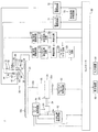
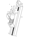
以下、本発明の一実施形態について図面を用いて説明する。図1は、第1実施形態に係るレーザ加工装置1の概略システム構成図である。このレーザ加工装置1は、加工対象物OBを固定支持する支持部材としてのテーブル21と、加工対象物OBに向けてレーザ光を照射して加工対象物OBをレーザ加工する加工ヘッド30とを備えている。加工対象物OBは、円盤状の薄板であって、レーザ加工されて最終的には、例えば反射防止膜や偏光板等の機能性材料として使用される。テーブル21は、円盤状に形成されていて、スピンドルモータ22およびフィードモータ23によって駆動される。加工ヘッド30は、装置本体に固定されたヘッド支持フレーム(図示略)により固定されている。
Hereinafter, an embodiment of the present invention will be described with reference to the drawings. FIG. 1 is a schematic system configuration diagram of a
スピンドルモータ22は、その回転により、回転軸22bを介してテーブル21を回転駆動する。スピンドルモータ22内には、同モータ22すなわちテーブル21の回転を検出して、その回転を表す回転検出信号を出力するエンコーダ22aが組み込まれている。この回転検出信号は、テーブル21の回転位置が一つの基準回転位置に来るごとに発生されるインデックス信号と、テーブル21が所定の微少な回転角度だけ回転するたびに電圧レベルがハイレベルとローレベルとに交互に切り替わるパルス列信号であって、互いにπ/2だけ位相のずれたA相信号およびB相信号とからなる。尚、この第1実施形態においては、回転検出信号としてパルス列信号のみが使用される。
The
回転検出信号は、スピンドルモータ制御回路53に供給される。スピンドルモータ制御回路53は、コントローラ90からの回転速度指示により作動開始し、エンコーダ22aから出力されるパルス列信号(A相信号およびB相信号)の単位時間あたりのパルス数によりスピンドルモータ22の回転速度を計算し、計算した回転速度がコントローラ90によって指示された回転速度に等しくなるようにスピンドルモータ22の回転を制御する。
The rotation detection signal is supplied to the spindle
フィードモータ23は、スクリューロッド24を回転させて、テーブル21を半径方向に駆動する。スクリューロッド24は、その一端にてフィードモータ23の回転軸に一体回転するように連結され、その他端に支持部材25に固着されたナット(図示しない)に螺合している。支持部材25は、スピンドルモータ22を固定支持するとともに、テーブル21の半径方向への移動のみが許容されている。従って、フィードモータ23が回転すると、スピンドルモータ22、テーブル21および支持部材25は、スクリューロッド24およびナットからなる送りネジ機構20によりテーブル21の径方向に変位する。テーブル21の移動方向は、テーブル21の回転中心の移動軌跡を表す直線が、加工ヘッド30の照射エリアを通るように設定されている。
The
フィードモータ23内にも、フィードモータ23の回転を検出して、前記エンコーダ22aと同様な回転検出信号(A相信号およびB相信号からなるパルス列信号)を出力するエンコーダ23aが組み込まれている。エンコーダ23aから出力されるパルス列信号は、フィードモータ制御回路54と半径位置検出回路52とに出力される。半径位置検出回路52は、エンコーダ23aからのパルス列信号のパルス数をフィードモータ23の回転方向に応じてカウントアップ又はカウントダウンし、そのカウント値からレーザ光が照射されるテーブル21の半径方向への送り位置(以下、半径位置と呼ぶ)を検出し、半径位置を表すデジタル信号をコントローラ90に出力する。尚、半径位置検出回路52におけるカウント値の初期設定は、電源投入時にコントローラ90の指示によって行われる。
Also incorporated in the
フィードモータ制御回路54は、コントローラ90の指示により、フィードモータ23を駆動制御して、レーザ光の照射位置をテーブル21の指定半径位置へ移動させたり、テーブル21を半径方向に指定速度で移動させる。具体的には、フィードモータ制御回路54は、コントローラ90によって指定される半径位置へのレーザ光の照射位置の移動が指定されたときには、半径位置検出回路52によって検出される半径位置を用いてフィードモータ23の回転を制御し、検出される半径位置がコントローラ90から指定された半径位置に等しくなるまでフィードモータ23を回転させる。またフィードモータ制御回路54は、コントローラ90によって指定される移動速度でレーザ光の照射位置をテーブル21の半径方向に移動させることが指示されたときには、エンコーダ23aからの回転検出信号からテーブル21の半径方向の移動速度を計算して、計算された移動速度がコントローラ90によって指定された移動速度と等しくなるようにフィードモータ23の回転を制御する。
The feed
次に、加工ヘッド30について説明する。加工ヘッド30は、第1レーザ光源31と第2レーザ光源41とを備え、各光源31,41から出射されたレーザ光を加工対象物OBに向けて照射するとともに、その反射光を別々に受光する構成となっている。第1レーザ光源31から出射されるレーザ光は、主に加工対象物OBをレーザ加工するために使用され、第2レーザ光源41から出射されるレーザ光は、加工対象物OBをレーザ加工できない弱い強度に調整され加工対象物OBの表面の異常部を検出するために使用される。以下、第1レーザ光源31から出射されるレーザ光を加工用レーザ光と呼び、第2レーザ光源41から出射されるレーザ光を検査用レーザ光と呼ぶ。尚、第1レーザ光源31は、フォーカスサーボを開始するときには、後述する第1レーザ駆動回路71からの駆動信号の調整により、加工対象物OBをレーザ加工できない弱い強度(以下、非加工強度と呼ぶ)のレーザ光をも出射できるようになっている。第1レーザ光源31から非加工強度のレーザ光を出射する場合についてのみ、そのレーザ光を非加工用レーザ光と呼ぶ。
Next, the
加工ヘッド30は、第1レーザ光源31、第1コリメートレンズ32、第1偏光ビームスプリッタ33、ダイクロイックミラー34、1/4波長板35、対物レンズ36、第1集光レンズ37、シリンドリカルレンズ38、第1フォトディテクタ39、フォーカスアクチュエータ40、第2レーザ光源41、第2コリメートレンズ42、第2偏光ビームスプリッタ43、第2集光レンズ44、第2フォトディテクタ45などを備えている。第1レーザ光源31から出射した加工用レーザ光は、第1コリメートレンズ32、第1偏光ビームスプリッタ33、ダイクロイックミラー34、1/4波長板35を透過して対物レンズ36により加工対象物OBの表面で集光する。また、加工対象物OBの表面に集光した加工用レーザ光は加工対象物OBの表面で反射する。加工対象物OBの表面で反射した反射光は、対物レンズ36により平行光になり、1/4波長板35、ダイクロイックミラー34をそのまま透過し、第1偏光ビームスプリッタ33に入射し、第1偏光ビームスプリッタ33によって反射されて第1集光レンズ37に入射する。第1集光レンズ37は、第1偏光ビームスプリッタ33による反射光をシリンドリカルレンズ38を介して第1フォトディテクタ39に集光させる。
The
第2レーザ光源41は、第1レーザ光源31とは異なる波長のレーザ光を出射する。第2レーザ光源41から出射した検査用レーザ光は、第2コリメートレンズ42および第2偏光ビームスプリッタ43を介してダイクロイックミラー34に入射する。ダイクロイックミラー34は、第1レーザ光源31から出射された加工用レーザ光およびその反射光に対してはそのまま透過させるが、第2レーザ光源41から出射された検査用レーザ光に対しては反射させる。ダイクロイックミラー34で反射した検査用レーザ光は、1/4波長板35、対物レンズ36を透過して加工対象物OBの表面に集光される。つまり、検査用レーザ光は、加工用レーザ光と合成されて1/4波長板35を透過して対物レンズ36により加工対象物OBの表面に集光される。
The second
この場合、ダイクロイックミラー34を反射した検査用レーザの光軸は、第1レーザ光源31から出射されダイクロイックミラー34を透過した加工用レーザの光軸に対して加工対象物OBの回転方向とは逆方向に僅かに傾けられている。従って、第2レーザ光源41から出射される検査用レーザ光は、第1レーザ光源31から出射される加工用レーザ光により加工対象物OBに照射されるスポット位置よりも加工対象物OBの回転方向とは逆方向に僅かに離れた位置に集光される。本実施形態においては、例えば、2つのレーザ光の加工対象物表面における集光位置の離隔が50μm程度に設定される。以下、加工対象物表面における加工用レーザ光の照射位置(光スポットの中心位置)と検査用レーザ光の照射位置(光スポットの中心位置)との間隔を、照射位置間隔DSと呼ぶ。
In this case, the optical axis of the inspection laser reflected from the
検査用レーザ光の加工対象物OBからの反射光は、対物レンズ36により平行光になり、1/4波長板35を透過し、ダイクロイックミラー34で反射する。従って、検査用レーザ光の反射光は、ダイクロイックミラー34で加工用レーザ光の反射光と分離される。ダイクロイックミラー34で反射した反射光は、第2偏光ビームスプリッタ43によって反射されて第2集光レンズ44に入射する。第2集光レンズ44は、第2偏光ビームスプリッタ43による反射光を第2フォトディテクタ45に集光する。第2フォトディテクタ45は、第2偏光ビームスプリッタ43によって反射された検査用レーザ光の強度に応じた信号を出力する。
The reflected light from the processing object OB of the inspection laser light becomes parallel light by the
第1レーザ光源31は、コントローラ90によって作動制御される第1レーザ駆動回路71によって駆動される。また、第2レーザ光源41は、コントローラ90によって作動制御される第2レーザ駆動回路72によって駆動される。第1レーザ駆動回路71は、発光信号供給回路73により第1レーザ光源31への駆動信号の出力形態が制御される。
The first
発光信号供給回路73は、コントローラ90から加工模様を表すデータを入力して、レーザ加工中に、そのデータに対応したパルス列信号、あるいは、連続信号を第1レーザ駆動回路71に供給する。発光信号供給回路73は、加工対象物OBの表面に複数の微細ピットを列状に形成する場合には、そのピットの長さ、ピットの形成間隔に応じた時間幅のハイレベル信号とローレベル信号からなるパルス列信号を出力し、加工対象物OBの表面に連続した溝を形成する場合には、連続したハイレベル信号を出力する。
The light emission
第1レーザ駆動回路71は、コントローラ90からの指令に基づいて、第1レーザ光源31に対して指定された強度のレーザ光を出射するための電流および電圧を供給する。第1レーザ駆動回路71は、コントローラ90から非加工強度のレーザ照射開始の指令を入力した場合には、それに応答して低レベル(すなわち非加工レベル)の直流信号からなる駆動信号を第1レーザ光源31に出力する。この非加工レベルは、第1レーザ光源31から出射されるレーザ光の加工対象物OBの表面への照射によって加工対象物OBの表面が変化しない(レーザ加工されない)程度に低く、かつ、後述するフォーカスサーボ制御を可能とするレベルに設定されている。
The first
また、第1レーザ駆動回路71は、コントローラ90から加工強度のレーザ照射開始の指令を入力した場合には、それに応答して高レベル(すなわち加工レベル)のパルス列信号あるいは直流信号からなる駆動信号を第1レーザ光源31に出力する。高レベルの駆動信号の波形は、発光信号供給回路73から入力した信号に応じて設定され、例えば、発光信号供給回路73から入力した信号がパルス列信号であれば、そのパルス信号波形に応じた波形となる。この加工レベルは、第1レーザ光源31から出射されるレーザ光の加工対象物OBの表面への照射によって加工対象物OBの表面がレーザ加工され、かつ、後述するフォーカスサーボ制御を可能とするレベルに設定されている。
When the first
加工用レーザ光の加工対象物OBの表面からの反射光は、第1フォトディテクタ39に導かれ受光される。第1フォトディテクタ39は、分割線で区切られた4つの同一正方形状の受光素子からなる4分割受光素子にて構成され、時計回りに配置された受光領域A,B,C,Dに入射した光の強度に比例した大きさの検出信号を受光信号(a,b,c,d)として出力する。第1フォトディテクタ39は、4つの受光素子が配置された中央に反射光が集光するように固定されている。
The reflected light from the surface of the processing object OB of the processing laser light is guided to the
第1フォトディテクタ39から出力される受光信号(a,b,c,d)は、第1信号増幅回路61に入力される。第1信号増幅回路61は、受光信号(a,b,c,d)をそれぞれ増幅してフォーカスエラー信号生成回路62に出力する。フォーカスエラー信号生成回路62は、増幅された受光信号(a’,b’,c’,d’)を使って演算によりフォーカスエラー信号を生成する。本実施形態においては、非点収差法によるフォーカスサーボ制御を用いているため、(a’+c’)−(b’+d’)の演算を行い、この演算結果をフォーカスエラー信号として導通回路63を介してフォーカスサーボ回路64に出力する。フォーカスエラー信号(a’+c’)−(b’+d’)は、図16に示すように、対物レンズと加工対象物表面との距離を変化させるとS字状波形信号となり、加工用レーザ光の焦点位置が加工対象物OBの表面と一致するときにはゼロの値をとり(図中におけるゼロクロス点P0)、焦点位置が加工対象物OBの表面からずれていると、そのずれ量およびずれ方向に応じた値をとる。この場合、焦点位置に近い点ではずれ量が大きくなるほどフォーカスエラー信号の絶対値も大きくなるが、ずれ量が大きくなりすぎるとフォーカスエラー信号の絶対値が減少する。従って、フォーカスサーボ制御可能な範囲は、図16に示すピーク点P1,P2間のS字検出エリア内となる。
The received light signals (a, b, c, d) output from the
導通回路63は、フォーカスエラー信号生成回路62とフォーカスサーボ回路64との間に設けられ、後述する遅延回路68からハイレベル信号が入力されている期間においては、フォーカスサーボ回路64に対してフォーカスエラー信号の疑似信号としてゼロレベル信号(焦点位置のずれ量ゼロを表す信号)を出力する。一方、遅延回路68からハイレベル信号が入力されていない期間においては、フォーカスエラー信号生成回路62から入力したフォーカスエラー信号をそのままフォーカスサーボ回路64に出力する。
The
フォーカスサーボ回路64は、コントローラ90により作動制御され、フォーカスエラー信号に基づいて、フォーカスサーボ信号を生成してドライブ回路65に出力する。ドライブ回路65は、このフォーカスサーボ信号に応じてフォーカスアクチュエータ40を駆動して、対物レンズ36をレーザ光の光軸方向に変位させる。対物レンズ36が変位するとレーザ光の焦点位置が加工対象物OBの表面に一致する近傍でフォーカスエラー信号(a’+c’)−(b’+d’)がS字状に変化する。フォーカスサーボ回路64は、フォーカスサーボ信号がS字状に変化する範囲の中間付近となるタイミングでフォーカスエラー信号(a’+c’)−(b’+d’)の値が一定値(ゼロ)となるようにドライブ回路65にフォーカスサーボ信号を供給することにより、加工対象物OBの表面にレーザ光を集光させ続けることができる。
The
第2レーザ駆動回路72は、コントローラ90からの指令に基づいて、第2レーザ光源41に対して、検査レベルの直流信号からなる駆動信号を第2レーザ光源41に出力する。この検査レベルは、第2レーザ光源41から出射されるレーザ光(検査用レーザ光)の加工対象物OBの表面への照射によって加工対象物OBの表面が変化しない(レーザ加工されない)程度に弱く設定されている。
The second
検査用レーザ光の加工対象物OBの表面からの反射光は、第2フォトディテクタ45に導かれ受光される。第2フォトディテクタ45は、入射した光の強度に比例した大きさの検出信号を受光信号として出力する。つまり、受光した光の強度が大きいほど大きな波高値となる受光信号を出力する。第2フォトディテクタ45から出力される受光信号は、第2信号増幅回路66に入力される。第2信号増幅回路66は、入力した受光信号を適切な信号レベルに増幅してマスク信号発生回路67に出力する。以下、第2信号増幅回路66により増幅された受光信号を、単に、受光信号と呼ぶ。
The reflected light from the surface of the workpiece OB of the inspection laser light is guided to the
マスク信号発生回路67は、コントローラ90から指示を受けると作動開始する。マスク信号発生回路67は、入力した受光信号の信号レベル(波高値)と比較するための第1基準レベルR1と、第1基準レベルR1よりも高い第2基準レベルR2との2つの基準レベルが設定されたコンパレータである。この2つの基準レベルR1,R2は、本発明の基準強度に相当するもので、正常な加工対象物OBの表面に検査用レーザ光を照射したときに得られる受光信号の波高値が取り得る正常範囲を設定したものである。従って、受光信号の波高値が第1基準レベルR1を下回る場合、あるいは、第2基準レベルR2を上回る場合には、検査用レーザ光が照射されている位置の加工対象物OBの表面に異物付着や傷といった異常部が存在するとみなすことができる。尚、加工対象物OBの表面が、受光信号の波高値が正常範囲に収まるような状態(異常部が存在しない状態)であれば、上述したフォーカスサーボ回路64によるフォーカスサーボが外れることはない。
The mask
マスク信号発生回路67は、受光信号の波高値が第1基準レベルR1以上で第2基準レベルR2以下となる正常範囲の値をとる場合には、ローレベル信号を遅延回路68に出力し、受光信号の波高値が第1基準レベルR1を下回る場合、あるいは、第2基準レベルR2を上回る異常範囲の値をとる場合には、ハイレベル信号を遅延回路68に出力する。以下、マスク信号発生回路67の出力する信号をマスク信号と呼ぶ。尚、一般的には、加工対象物OBの表面に異常部が存在するとその反射光の強度は低下するが、稀に、反射光の強度が上昇する場合もある。そこで、本実施形態においては、高低2つの基準レベルR1,R2を設けて異常部の存在を判定するが、1つの基準レベルによる判定、つまり、反射光の強度が基準レベルR1よりも下回ったときにのみ異常部が存在すると判定してハイレベル信号を出力する構成であってもよい。
The mask
ここで、受光信号の波高値の推移と、それに伴って変化するマスク信号について図3を用いて説明する。図3に示すように、受光信号の波高値が第1基準レベルR1と第2基準レベルR2との間に収まっているあいだは、マスク信号はローレベルを維持する。検査用レーザ光の光スポットが加工対象物OBの異常部に入ると、受光信号の波高値が低下する。そして、受光信号の波高値が第1基準レベルR1を下回ると(時刻t1)、マスク信号は、ローレベルからハイレベルに切り替わる。その後、検査用レーザ光の光スポットが異常部から抜け出ると受光信号の波高値が増大する。そして、受光信号の波高値が第1基準レベルR1以上になると(時刻t2)、マスク信号は、再びローレベルに切り替わり、その状態を維持する。 Here, the transition of the peak value of the received light signal and the mask signal that changes along with this will be described with reference to FIG. As shown in FIG. 3, while the peak value of the received light signal is between the first reference level R1 and the second reference level R2, the mask signal maintains a low level. When the light spot of the inspection laser light enters the abnormal part of the object OB, the peak value of the received light signal decreases. When the peak value of the received light signal falls below the first reference level R1 (time t1), the mask signal switches from the low level to the high level. Thereafter, when the light spot of the inspection laser light exits from the abnormal portion, the peak value of the light reception signal increases. When the peak value of the received light signal becomes equal to or higher than the first reference level R1 (time t2), the mask signal is switched to the low level again and maintains that state.
遅延回路68は、図2に示すように、第1遅延回路681と第2遅延回路682とフリップフロップ回路683とを備えている。第1遅延回路681および第2遅延回路682には、マスク信号発生回路67の出力するマスク信号が入力される。第1遅延回路681は、コントローラ90から遅延量d1を表す信号を入力し、マスク信号を遅延量d1だけ遅延させた第1遅延信号を出力する。また、第2遅延回路682は、コントローラ90から遅延量d2(>d1)を表す信号を入力し、マスク信号を遅延量d2だけ遅延させた第2遅延信号を出力する。この遅延量d1、d2は、以下のようにコントローラ90にて計算される。
d1=(DS/v)−A ……(1)
d2=(DS/v)+A ……(2)
ここで、DSは、加工対象物OBの表面における加工用レーザ光の照射位置と検査用レーザ光の照射位置との間隔(照射位置間隔)を表し、vは、テーブル21の回転により加工用レーザ光の照射位置が加工対象物OBの表面を移動する線速度であり、Aは、予め設定した正の微少値である。
As shown in FIG. 2, the
d1 = (DS / v) −A (1)
d2 = (DS / v) + A (2)
Here, DS represents the interval (irradiation position interval) between the irradiation position of the processing laser beam and the irradiation position of the inspection laser beam on the surface of the processing object OB, and v represents the processing laser by the rotation of the table 21. The light irradiation position is a linear velocity at which the surface of the workpiece OB moves, and A is a positive fine value set in advance.
フリップフロップ回路683は、第1遅延回路681の出力信号と第2遅延回路682の出力信号とを入力し、その出力信号を、第1遅延信号の立ち上がり(ローレベルからハイレベルへの切り替わり時)でローレベルからハイレベルに切り替え、第2遅延信号の立ち下がり(ハイレベルからローレベルへの切り替わり時)でハイレベルからローレベルに切り替えるものである。このフリップフロップ回路683の出力信号は、導通回路63に出力され、フォーカスサーボをホールドするための信号として使われる。
The flip-
導通回路63は、フリップフロップ回路683の出力信号を入力し、その出力信号がハイレベルとなっているときに、フォーカスサーボ回路64に対してフォーカスエラー信号の疑似信号としてゼロレベル信号(焦点位置のずれ量ゼロを表す信号)を出力する。従って、フリップフロップ回路683の出力信号がハイレベルとなっている期間においては、フォーカスエラー信号がゼロレベル信号に維持されるため、フォーカスサーボ回路64はドライブ回路65に対して強度が一定となるフォーカスサーボ信号を出力し、ドライブ回路65はフォーカスアクチュエータ40に対して強度が一定となる駆動信号を出力する。従って、対物レンズ36が同じ位置(フリップフロップ回路683の出力がハイレベルになる直前の位置)に保持されて移動しない状態となる。つまり、フォーカスサーボがホールドされる。このように、フリップフロップ回路683の出力信号は、フォーカスサーボのホールドに用いられるため、以下、その出力信号をホールド信号と呼ぶ。
The
ここで、フォーカスサーボをホールドするタイミングについて、図3を用いて説明する。検査用レーザ光の光スポットが加工対象物OBの異常部に入ると、受光信号の波高値が低下して第1基準レベルR1を下回り(時刻t1)、その後、検査用レーザ光の光スポットが異常部から抜け出ると受光信号の波高値が増大して第1基準レベルR1以上に戻る(時刻t2)。従って、マスク信号は、時刻t1から時刻t2のあいだハイレベルを維持する。第1遅延回路681は、このマスク信号を遅延量d1だけ遅延させた第1遅延信号を出力する。つまり、時刻t3(=t1+d1)から時刻t5(=t2+d1)のあいだ、ハイレベル信号を出力する。一方、第2遅延回路682は、マスク信号を遅延量d2だけ遅延させた第2遅延信号を出力する。つまり、時刻4(=t1+d2)から時刻t6(t2+d2)のあいだ、ハイレベル信号を出力する。
Here, the timing of holding the focus servo will be described with reference to FIG. When the light spot of the inspection laser beam enters the abnormal part of the workpiece OB, the peak value of the received light signal decreases and falls below the first reference level R1 (time t1). When exiting from the abnormal part, the peak value of the received light signal increases and returns to the first reference level R1 or higher (time t2). Therefore, the mask signal maintains a high level from time t1 to time t2. The
フリップフロップ回路683は、この第1遅延信号の立ち上がりから第2遅延信号の立ち下がりまでの期間、つまり、時刻t3から時刻t6までのあいだハイレベル信号を出力する。従って、この時刻t3から時刻t6のあいだだけフォーカスサーボがホールドされる。
The flip-
本実施形態のレーザ加工装置1においては、後述するように、加工対象物OBをセットしたテーブル21を回転させながら半径方向に送り移動させている状態で、加工ヘッド30の第1レーザ光源31から加工用レーザ光を照射することにより加工対象物OBの表面をレーザ加工する。それと同時に、検査用レーザ光を加工用レーザ光が照射される直前の位置に照射する。レーザ加工中において、検査用レーザ光の反射光の強度が正常範囲から外れているときには、マスク信号発生回路67からハイレベルのマスク信号が出力される。従って、このマスク信号がハイレベルとなっているときは、検査用レーザ光が異常部を照射していることになる。検査用レーザ光の照射位置は、加工用レーザ光の照射位置に対して照射位置間隔DSだけ加工方向にシフトした位置となっている。従って、加工用レーザ光が異常部を照射する前に、異常部の存在を事前に検出してフォーカスサーボをホールドすることができる。
In the
図3に破線で示した波形は、加工用レーザ光の照射位置において、反射光の強度を検出した場合の波高値を表す。尚、この例は、一定強度の加工用レーザ光を照射している(溝加工を行っている)例である。マスク信号発生回路67に入力される受光信号波形に対して、この波形の遅れ時間は、DS/vとして表すことができる。従って、時刻t1からこの遅れ時間(DS/v)が経過する前にフォーカスサーボをホールドすれば、フォーカスサーボが外れることがない。そこで、本実施形態においては、上述の(1)式に示すように、時刻t1から遅れ時間(DS/v)が経過する時点よりも微少値(微少時間)Aだけ先にホールド信号がハイレベルに切り替わるように設定している。また、フォーカスサーボのホールドは、加工用レーザ光の光スポットが異常部が抜け出るまで継続する必要がある。そこで、本実施形態においては、上述の(2)式に示すように、時刻t2から遅れ時間(DS/v)経過した時点より更に微少値(微少時間)Aだけ遅れてホールド信号がローレベルに切り替わるように設定している。従って、図3に破線で示した反射光の波高値が第1基準レベルR1を下回っている期間においては、確実にホールド信号がハイレベルになる。この結果、フォーカスサーボのホールド開始とホールド解除のタイミングを適切に設定でき、異常部によってフォーカスサーボが外れてしまうことを防止できる。
A waveform indicated by a broken line in FIG. 3 represents a peak value when the intensity of the reflected light is detected at the irradiation position of the processing laser light. This example is an example in which a processing laser beam having a certain intensity is irradiated (groove processing is performed). The delay time of this waveform with respect to the received light signal waveform input to the mask
次に、レーザ加工装置1の動作を説明する。作業者は、レーザ加工装置1の図示しない電源スイッチをオンして、図1に示す各種回路の作動を開始させる。電源投入時には、コントローラ90は、図示しないプログラムの実行により、半径位置検出回路52およびフィードモータ制御回路54に対して初期設定を指示する。この指示によりフィードモータ制御回路54は、フィードモータ23を回転させてテーブル21を駆動限界位置である初期位置に移動させる。テーブル21が初期位置まで達してフィードモータ23の回転が停止すると、半径位置検出回路52はエンコーダ23aからのパルス列信号の入力停止を検出して、カウント値を「0」にリセットし、フィードモータ制御回路54に出力停止のための信号を出力して初期設定が完了する。
Next, the operation of the
次に、コントローラ90は、図示しないプログラムの実行により、表示装置92を用いて、加工対象物OBの加工に必要な加工データの入力を作業者に促す。作業者は、入力装置91を用いて、レーザ加工開始半径位置、レーザ加工終了半径位置、半径方向の加工ピッチ、加工対象物OBに対するレーザスポットの回転線速度、溝加工またはピット加工の指定、ピット加工の場合には回転方向のピット間隔などを入力する。コントローラ90は、入力された加工データを内部の記憶装置に記憶する。尚、加工データがコントローラ90内に記憶されている場合には、この処理を省略してもよい。
Next, the
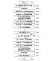
このような初期処理の実行後、レーザ加工ルーチンが開始される。図4は、レーザ加工ルーチンを示すフローチャートである。このレーザ加工ルーチンは、コントローラ90のROM内に制御プログラムとして記憶されており、ステップS10にて開始される。コントローラ90は、まず、ステップS12において、フィードモータ制御回路54に前記入力されたレーザ加工開始半径位置に移動するように指示する。フィードモータ制御回路54は、半径位置検出回路52によって検出された半径位置を入力しながら、レーザ光の照射位置がレーザ加工開始半径位置に一致するまで、フィードモータ23の回転を制御してテーブル21を移動する。
After execution of such initial processing, a laser processing routine is started. FIG. 4 is a flowchart showing a laser processing routine. This laser processing routine is stored as a control program in the ROM of the
続いて、コントローラ90は、ステップS14において、前記入力されたレーザ加工開始半径位置および回転線速度を用いて、スピンドルモータ22の回転速度を計算し、この計算した回転速度をスピンドルモータ制御回路53に出力するとともにスピンドルモータ22の回転開始を指示する。スピンドルモータ制御回路53は、エンコーダ22aからのA相信号およびB相信号を用いてスピンドルモータ22の回転速度を計算し、この計算した回転速度がコントローラ90から入力された回転速度に等しくなるようにスピンドルモータ22の回転制御を開始する。尚、コントローラ90は、回転開始指示を出力した後は、本ルーチンとは別の割り込みルーチンにより、スピンドルモータ22の回転速度の計算を繰り返し、その都度、計算した回転速度をスピンドルモータ制御回路53に出力する。
Subsequently, the
続いて、コントローラ90は、ステップS16において第1レーザ駆動回路71に対して非加工用レーザ光照射の開始を指示する。これにより、第1レーザ駆動回路71は、第1レーザ光源31に対して、非加工レベルの駆動信号の出力を開始する。第1レーザ光源31は、この駆動信号により非加工用レーザ光を出射する。こうして加工対象物OBの表面には、非加工用レーザ光の光スポットが形成され、この光スポットの反射光が第1フォトディテクタ39によって検出される。この場合、加工対象物OBは、非加工用レーザ光の照射によっては加工されない。
Subsequently, the
続いて、コントローラ90は、ステップS18において、第2レーザ駆動回路72に対して検査用レーザ光の照射開始を指示する。これにより、第2レーザ駆動回路72は、第2レーザ光源41に対して、検査レベルの一定の駆動信号の出力を開始する。第2レーザ光源41は、この駆動信号により検査用レーザ光を出射する。こうして加工対象物OBの表面には、非加工用レーザ光の光スポットから照射位置間隔DSだけ離れた位置に検査用レーザ光の光スポットが形成され、この光スポットの反射光が第2フォトディテクタ45によって検出される。この場合、加工対象物OBは、検査用レーザ光の照射によっては加工されない。
Subsequently, in step S18, the
続いて、コントローラ90は、ステップS20において、マスク信号発生回路67および遅延回路68に対して作動開始の指示を行う。この場合、コントローラ90は、上述した(1)式、(2)式を使って遅延量d1、d2を計算し、その計算値を第1遅延回路681、第2遅延回路682に出力する。
Subsequently, the
続いて、コントローラ90は、ステップS22において、フォーカスサーボ回路64および図示しないフォーカスアクチュエータ40を駆動する回路とS字検出回路に作動開始を指示する。これにより、図16に示すS字信号波形の中間付近のタイミングでフォーカスサーボ回路64が作動開始し、非加工用レーザ光の焦点位置が加工対象物OBの表面に常に一致するように、対物レンズ36の位置が光軸方向に変位する制御が開始される。続いて、コントローラ90は、ステップS24において、第1レーザ駆動回路71に対して加工用レーザ光の照射開始を指示するとともに、発光信号供給回路73に信号の出力を指示する。これにより、第1レーザ駆動回路71は、第1レーザ光源31に出力していた駆動信号を、非加工レベルから加工レベルに切り替え、発光信号供給回路73から供給される信号の波形に応じた波形にする。こうして、第1レーザ光源31は、加工レベルに対応した加工用レーザ光を出射する。従って、加工対象物OBには加工用レーザ光が照射され、加工対象物OBのレーザ加工が開始される。
Subsequently, in step S22, the
続いて、コントローラ90は、ステップS26において、フィードモータ制御回路54に対して、半径方向への移動開始を指示する。この場合、コントローラ90は、前記入力された回転線速度および加工ピッチ、半径位置検出回路52から取り込んだ半径位置に基づいて移動速度を計算し、フィードモータ制御回路54に対して移動速度を指示する。フィードモータ制御回路54は、エンコーダ23aからのA相信号およびB相信号を用いてフィードモータ23の半径方向の移動速度を計算し、この計算した移動速度がコントローラ90から指示された移動速度に等しくなるようにフィードモータ23の回転を制御する。この結果、テーブル21は、指示された移動速度で半径方向に移動し始める。尚、コントローラ90は、半径方向への移動開始を指示した後は、本ルーチンとは別の割り込みルーチンにより、テーブル21の移動速度の計算を繰り返し、その都度、計算した移動速度をフィードモータ制御回路54に出力する。
Subsequently, in step S26, the
こうして、テーブル21の回転と半径方向への移動とにより、加工対象物OBと加工ヘッド30との相対位置が変化し、加工用レーザ光と検査用レーザ光の照射位置が加工対象物OBの表面を螺旋状に移動していく。従って、加工用レーザ光の照射軌跡に沿って加工対象物OBの表面にレーザ加工が施されると同時に、レーザ加工直前の加工対象物OBの表面に検査用レーザ光が照射される。
Thus, the relative position between the processing object OB and the
続いて、コントローラ90は、ステップS28において、半径位置検出回路52から出力される半径位置データを取り込み、ステップS30において、加工終了半径位置に到達したか否かを判断する。加工終了半径位置は、作業者がレーザ加工開始にあたって入力設定した値である。ステップS28,S30の処理は、半径位置検出回路52により検出される半径位置が加工終了半径位置に一致するまで繰り返される。従って、この間は、加工用レーザ光照射による加工対象物OBのレーザ加工が継続される。同時にレーザ加工直前位置での検査用レーザ光の反射光強度に基づく異常部の検出が行われる。そして、異常部が検出された場合には、その検出期間のあいだだけマスク信号発生回路67からマスク信号が遅延回路68に出力され、このマスク信号に基づいて遅延回路68がホールド信号を作成する。このホールド信号により、加工用レーザ光が異常部を照射している期間においてフォーカスサーボがホールドされる。
Subsequently, the
半径位置検出回路52により検出される半径位置が加工終了半径位置に達すると(S30:Yes)、コントローラ90は、ステップS32において、フォーカスサーボ回路64に作動停止を指示して、フォーカスサーボ回路64によるフォーカスサーボ制御を停止させる。次に、コントローラ90は、ステップS34において、第2レーザ駆動回路72に対して検査用レーザ光の照射停止を指示し、ステップS36において、第1レーザ駆動回路71に対して加工用レーザ光の照射停止を指示する。これにより、検査用レーザ光および加工用レーザ光の照射が停止される。続いて、コントローラ90は、ステップS38において、マスク信号発生回路67および遅延回路68に対して作動停止の指示を行う。
When the radius position detected by the radius
続いて、コントローラ90は、ステップS40においてスピンドルモータ制御回路53に対して回転停止を指示し、ステップS42においてフィードモータ制御回路54に対して半径方向への移動停止を指示する。これにより、スピンドルモータ22およびフィードモータ23が停止する。こうしてテーブル21の回転と半径方向への移動が停止すると、ステップS44により本レーザ加工ルーチンが終了する。
Subsequently, the
以上説明した第1実施形態のレーザ加工装置1によれば、加工用レーザ光の光スポットの加工方向前方位置に検査用レーザ光を照射し、その反射光の強度に基づいてレーザ加工直前位置における異常部を検出する。そして、異常部を検出した場合には、加工用レーザ光が異常部を照射するまでの時間遅れを考慮してホールド信号を作成する。つまり、加工用レーザ光の光スポットが異常部に入る直前にホールド信号をハイレベルにし、光スポットが異常部から抜け出た直後にホールド信号をローレベルに戻す。これにより、加工用レーザ光が異常部を照射している期間においては、ホールド信号がハイレベルに維持され、導通回路63がフォーカスサーボ回路64に対してフォーカスエラー信号をゼロとして出力する。従って、この期間は、フォーカスサーボがホールドされる。そして、加工用レーザ光の光スポットが異常部から抜け出ると、ホールド信号がローレベルに戻り、導通回路63がフォーカスエラー信号生成回路62により生成されたフォーカスエラー信号をそのままフォーカスサーボ回路64に出力するようになり、フォーカスサーボのホールドが解除される。この結果、加工対象物OBの表面に異常部が存在しても正常なレーザ加工を継続することができ、加工対象物OBの損失や加工時間の無駄を低減することができる。
According to the
尚、マスク信号がハイレベルとなっている期間が本発明の異常期間に相当し、ホールド信号がハイレベルになっている期間が本発明の制御モード切替期間に相当する。また、フォーカスエラー信号をゼロレベル信号にしてフォーカスサーボをホールドする制御モードが本発明の異常検出時モードに相当し、フォーカスエラー生成回路62により生成されたフォーカスエラー信号をフォーカスサーボ回路64に出力してフォーカスサーボ制御を行う制御モードが本発明の通常モードに相当する。
The period during which the mask signal is at the high level corresponds to the abnormal period of the present invention, and the period during which the hold signal is at the high level corresponds to the control mode switching period of the present invention. The control mode in which the focus error signal is set to the zero level signal and the focus servo is held corresponds to the abnormality detection mode of the present invention, and the focus error signal generated by the focus
次に、第2実施形態のレーザ加工装置について説明する。上述した第1実施形態においては、レーザ加工直前位置で異常部を検出した場合にフォーカスサーボをホールドする構成を採用したが、第2実施形態においては、焦点位置の制御範囲の大小異なる2つのフォーカスサーボ系、つまり、S字検出距離の異なる2つのフォーカスサーボ系を備えて、レーザ加工中にフォーカスサーボ系を切り替える構成を採用する。また、第1実施形態においては、テーブル21に1つの加工対象物OBをセットしてレーザ加工するレーザ加工装置について説明したが、第2実施形態のレーザ加工装置は、テーブル21に複数の加工対象物OBをセットして、複数の加工対象物OBに対して同時にレーザ加工を行う構成を採用する。図5は、第2実施形態としてのレーザ加工装置2の概略構成図、図6は、加工対象物OBのテーブル21へのセット方法を表す説明図、図7は、加工対象物OBがテーブル21にセットされた状態を表す概略斜視図である。以下、第1実施形態と相違する構成について説明し、第1実施形態と同一の構成については、図面に第1実施形態と同一の符号を付して説明を省略する。
Next, the laser processing apparatus of 2nd Embodiment is demonstrated. In the first embodiment described above, a configuration is adopted in which the focus servo is held when an abnormal portion is detected at a position immediately before laser processing. However, in the second embodiment, two focus points having different control ranges of the focus position are used. A servo system, that is, two focus servo systems having different S-shaped detection distances, and a configuration in which the focus servo system is switched during laser processing is adopted. Moreover, in 1st Embodiment, although the laser processing apparatus which sets the one process target OB to the table 21 and laser-processes was demonstrated, the laser processing apparatus of 2nd Embodiment has several process object in the table 21. FIG. A configuration in which an object OB is set and laser processing is simultaneously performed on a plurality of workpieces OB is employed. FIG. 5 is a schematic configuration diagram of the
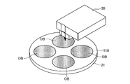
第2実施形態のレーザ加工装置2においては、複数の加工対象物OBが固定治具110を介してテーブル21にセットされる。固定治具110は、図6に示すように、加工対象物OBをテーブル21の回転軸まわりに複数枚(本実施形態では4枚)並べて固定するための固定円孔110hが穿設された薄い円盤であり、テーブル21の上面に載置される。各固定円孔110hは、その中心(円中心)が固定治具110の中心から半径rcだけ離れた位置にて周方向に等間隔(90度)に配置される。加工対象物OBは、全て同一形状であり、固定円孔110hに厚さ方向に挿入することにより固定治具110に同一平面上に固定される。固定治具110の厚さは、加工対象物OBの厚さと略同一に形成される。
In the
テーブル21の上面には複数の吸引孔21aが形成されており、図示しない吸引装置の作動により、吸引孔21aに負圧を発生させて固定治具110と加工対象物OBとをテーブル21の上面に吸引固定する。固定治具110は、テーブル21に対して固定治具110の中心がテーブル21の中心と一致するように、図示しないガイドにより位置決めされる。
A plurality of suction holes 21 a are formed on the upper surface of the table 21, and a negative pressure is generated in the suction holes 21 a by operating a suction device (not shown) so that the fixing
この第2実施形態のレーザ加工装置2においては、テーブル21の回転角度を検出するために回転角度検出回路55を備えている。回転角度検出回路55は、コントローラ90からの指示により作動を開始し、エンコーダ22aから出力されるパルス列信号のパルス数をカウントし、そのカウント値からテーブル21の回転角度を計算する。回転角度検出回路55は、テーブル21の回転角度の計算にあたって、エンコーダ22aからインデックス信号を入力したときにパルス数のカウント値をゼロクリア、つまり、テーブル21の回転角度を0°とする。そして、インデックス信号を入力した後のパルス列信号のカウント値から、回転角度0°を基準としたテーブル21の回転角度(回転角度位置)を計算する。回転角度検出回路55は、回転角度の計算を所定の短い周期で繰り返し、その都度、計算した回転角度を表すデジタル信号を後述する切替信号発生回路56とコントローラ90とに出力する。
The
次に、加工ヘッド300について説明する。第2実施形態における加工ヘッド300は、第1実施形態の加工ヘッド30に対して、ビームスプリッタ46、第3集光レンズ47、第2シリンドリカルレンズ48、第3フォトディテクタ49を加えたものである。ビームスプリッタ46は、第1偏光ビームスプリッタ33とダイクロイックミラー34との間に設けられている。第1レーザ光源31から出射され第1コリメートレンズ32で平行光となった加工用レーザ光は、第1偏光ビームスプリッタ33で殆どが透過し、ビームスプリッタ46で半分程度が透過する。ビームスプリッタ46を透過した加工用レーザ光は、ダイクロイックミラー34を透過し、1/4波長板35にて円偏光となって対物レンズ36にて集光され、加工対象物OBまたは固定治具110に照射される。加工対象物OBまたは固定治具110の表面で反射した反射光は、対物レンズ36により平行光となり、1/4波長板35により偏光方向が90度変わり、ダイクロイックミラー34をそのまま透過して、ビームスプリッタ46に入射する。
Next, the
ビームスプリッタ46に入射した反射光は、その半分程度が透過し、残り半分程度が反射する。ビームスプリッタ46に入射して透過したレーザ光は、第1偏光ビームスプリッタ33に入射し、その殆どが反射する。第1偏光ビームスプリッタ33で反射した反射光は、第1集光レンズ37、シリンドリカルレンズ38を介して第1フォトディテクタ39に集光する。以下、第1集光レンズ37、シリンドリカルレンズ38、第1フォトディテクタ39を総称して第1受光光学系と呼ぶ。
About half of the reflected light incident on the
ビームスプリッタ46の反射方向には、第3集光レンズ47、第2シリンドリカルレンズ48、第3フォトディテクタ49が設けられており、ビームスプリッタ46で反射した反射光は、第3集光レンズ47、第2シリンドリカルレンズ48を介して第3フォトディテクタ49に集光する。この第3フォトディテクタ49は、第1フォトディテクタ39と同様に、分割線で区切られた4つの同一正方形状の受光素子からなる4分割受光素子にて構成され、時計回りに配置された受光領域A,B,C,Dに入射した光の強度に比例した大きさの検出信号を受光信号(a,b,c,d)として出力する。以下、第3集光レンズ47、第2シリンドリカルレンズ48、第3フォトディテクタ49を総称して第2受光光学系と呼ぶ。
A
第1(第2)受光光学系におけるS字検出距離は、集光レンズ37(47)とシリンドリカルレンズ38(48)の配置等により調整できる。第1受光光学系においては、一般の光ディスク装置と同程度に短いS字検出距離が設定されており、第2受光光学系においては、第1受光光学系に比べて長いS字検出距離が設定されている。従って、S字検出距離の短い第1受光光学系においては、追従性の良い、精度の高いフォーカスサーボを行う場合に適しており、S字検出距離の長い第2受光光学系においては、追従性は劣るが広い焦点位置の制御可能範囲のフォーカスサーボを行う場合に適している。 The S-shaped detection distance in the first (second) light receiving optical system can be adjusted by the arrangement of the condenser lens 37 (47) and the cylindrical lens 38 (48). In the first light receiving optical system, an S-shaped detection distance as short as that of a general optical disc apparatus is set, and in the second light receiving optical system, an S-shaped detection distance longer than that in the first light receiving optical system is set. Has been. Therefore, the first light receiving optical system with a short S-shaped detection distance is suitable for performing focus servo with good followability and high accuracy, and the second light receiving optical system with a long S-shaped detection distance is suitable for following. Is inferior, but is suitable for focus servo within a controllable range of a wide focal position.
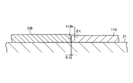
ところで、固定治具110は、その厚さが加工対象物OBの厚さと同一となるように形成されるが、実際には、図8に示すように、加工対象物OBの加工面と固定治具110の表面(テーブル21と当接しない側の面)との間に段差Δtが存在する。この段差Δtが加工用レーザ光の焦点位置の制御可能範囲を超えるほど大きいとフォーカスサーボが外れてしまう。レーザ加工時においては、第1実施形態と同様に、テーブル21を回転させながら半径方向に送り移動させている状態で、第1レーザ光源31から加工用レーザ光を照射することにより加工対象物OBの表面をレーザ加工する。従って、加工用レーザ光は、固定治具110の表面にも周期的に照射され、それと同時にフォーカスサーボ制御も行われる。
By the way, the fixing
加工対象物OBを高精度にレーザ加工するためには、加工用レーザ光の焦点位置が加工対象物OBの表面に良好に追従するようにS字検出距離を短くしてフォーカスサーボ制御を行う必要がある。この場合、フォーカスエラー信号から得られるS字波形信号のピーク点(P1,P2)の中間位置を基準とし、この中間位置から外れている距離だけフォーカスアクチュエータ40により対物レンズ36がレーザ光の光軸方向に駆動される。こうしたフォーカスサーボ制御は、フォーカスエラー信号からS字波形信号が得られる範囲、つまり、図16に示すS字検出エリア内において可能となっている。従って、加工用レーザ光の照射位置が加工対象物OBから固定治具110へ移動したとき、段差Δtの影響でフォーカスエラー信号がS字検出エリア外になりフォーカスサーボが外れてしまうおそれがある。
In order to perform laser processing of the processing object OB with high accuracy, it is necessary to perform focus servo control by shortening the S-shaped detection distance so that the focal position of the processing laser light follows the surface of the processing object OB satisfactorily. There is. In this case, the intermediate position of the peak points (P1, P2) of the S-shaped waveform signal obtained from the focus error signal is used as a reference, and the
そこで、この第2実施形態においては、第1受光光学系に接続される第1フォーカスサーボ系回路81と、第2受光光学系に接続される第2フォーカスサーボ系回路82とを備え、この2つのフォーカスサーボ系回路81,82を切り替えることによりフォーカスサーボの外れを防止する。第1フォーカスサーボ系回路81は、第1受光光学系の第1フォトディテクタ39から出力される受光信号(a,b,c,d)を増幅する信号増幅回路81aと、信号増幅回路81aにより増幅された信号(a’,b’,c’,d’)から非点収差法による演算である(a’+c’)−(b’+d’)の演算を行い演算結果をフォーカスエラー信号として生成するフォーカスエラー信号生成回路81bと、そのフォーカスエラー信号に基づいてフォーカスサーボ信号を生成するフォーカスサーボ回路81cとを備える。以下、第1フォーカスサーボ系回路81と第1受光光学系とをまとめて第1フォーカスサーボ系と呼ぶ。
Therefore, the second embodiment includes a first focus
また、第2フォーカスサーボ系回路82は、第2受光光学系の第3フォトディテクタ49から出力される受光信号(a,b,c,d)を増幅する信号増幅回路82aと、信号増幅回路82aにより増幅された信号(a’,b’,c’,d’)から非点収差法による演算である(a’+c’)−(b’+d’)の演算を行い演算結果をフォーカスエラー信号として生成するフォーカスエラー信号生成回路82bと、そのフォーカスエラー信号に基づいてフォーカスサーボ信号を生成するフォーカスサーボ回路82cとを備える。以下、第2フォーカスサーボ系回路82と第2受光光学系とをまとめて第2フォーカスサーボ系と呼ぶ。
The second focus
フォーカスサーボ回路81c,82cは、それぞれフォーカスサーボ信号を信号切替回路83に出力する。信号切替回路83は、後述する切替信号発生回路56あるいはエラー検出回路76から第1信号を入力した場合には、第1フォーカスサーボ系のフォーカスサーボ回路81cとドライブ回路65とを接続してフォーカスサーボ回路81cの出力するフォーカスサーボ信号をドライブ回路65に出力する状態にし、切替信号発生回路56あるいはエラー検出回路76から第2信号を入力した場合には、第2フォーカスサーボ系のフォーカスサーボ回路82cとドライブ回路65とを接続してフォーカスサーボ回路82cの出力するフォーカスサーボ信号をドライブ回路65に出力する状態にする。ドライブ回路65は、信号切替回路83を経由して入力したフォーカスサーボ信号に応じてフォーカスアクチュエータ40を駆動制御して、対物レンズ36をレーザ光の光軸方向に変位させる。尚、レーザ加工装置2の起動時においては、信号切替回路83は、コントローラ90から第2信号を入力し、第2フォーカスサーボ系のフォーカスサーボ回路82cとドライブ回路65とを接続してフォーカスサーボ回路82cから入力したフォーカスサーボ信号をドライブ回路65に出力する状態にする。
The
上述したように、第1受光光学系においてはS字検出距離が短く設定され、第2受光光学系においてはS字検出距離が長く設定されている。従って、加工用レーザ光を加工対象物OBの表面に照射してレーザ加工する場合には、第1フォーカスサーボ系を使って追従性の良いフォーカスサーボ制御を行い、加工用レーザ光が固定治具110の表面、および、加工対象物OBと固定治具110との境界を照射するときには、フォーカスサーボが外れないように第2フォーカスサーボ系を使ってフォーカスサーボ制御を行うとよい。
As described above, the S-shaped detection distance is set short in the first light receiving optical system, and the S-shaped detection distance is set long in the second light receiving optical system. Accordingly, when laser processing is performed by irradiating the surface of the processing object OB with the processing laser beam, the first focus servo system is used to perform focus servo control with good followability, and the processing laser beam is fixed to the fixture. When irradiating the surface of 110 and the boundary between the workpiece OB and the fixing
そこで、第2実施形態においては、テーブル21の回転角度に基づいて、加工用レーザ光が加工対象物OBの表面を照射している場合と、固定治具110の表面、および、加工対象物OBと固定治具110との境界を照射している場合とで2つのフォーカスサーボ系を切り替える切替信号発生回路56を備えている。切替信号発生回路56は、レーザ加工中において、回転角度検出回路55から出力されるテーブル21の回転角度と、半径位置検出回路から出力されるテーブル21の半径位置とを入力し、固定治具110にセットされた加工対象物OBと加工用レーザ光の照射位置との位置関係に基づいて、フォーカスサーボ系を切り替える演算回路でありマイクロコンピュータを主要部として備えている。切替信号発生回路56は、加工用レーザ光の照射位置が固定治具110から加工対象物OBに移動した後に第1信号を出力し、加工用レーザ光の照射位置が加工対象物OBから固定治具110に移動する手前で第2信号を出力する。この切替信号発生回路56の動作の詳細については後述する。
Therefore, in the second embodiment, based on the rotation angle of the table 21, the case where the processing laser light irradiates the surface of the processing object OB, the surface of the fixing
加工対象物OBは固定治具110の固定円孔110hに挿入固定されるが、図8に示すように、加工対象物OBの外周面と固定円孔110hの内周面とのあいだに隙間Δxが生じてしまうことがある。この隙間Δxが存在すると、加工対象物OBと固定治具110との境界を加工用レーザ光の光スポットが通過するときフォーカスエラー信号が乱れる。このため、フォーカスエラー信号の乱れに基づいて加工用レーザ光の焦点位置が制御されてしまい、フォーカスサーボが外れるおそれがある。各フォーカスサーボ回路81b,82bは、それぞれ入力したフォーカスエラー信号の高周波成分をカットするローパスフィルタ機能を備えており、このローパスフィルタのカットオフ周波数を低くすることで外乱に対して反応しないように設定できる。
The workpiece OB is inserted and fixed in the fixed
そこで、第2実施形態においては、第2フォーカサーボ系におけるフォーカスサーボ回路82cのカットオフ周波数を、第1フォーカスサーボ系のフォーカスサーボ回路81cのカットオフ周波数に比べて低く設定する。例えば、第2フォーカサーボ系におけるフォーカスサーボ回路82cのカットオフ周波数fcを、隙間Δxにより発生する信号成分の周波数の2.5分の1〜15分の1相当に設定する。この関係式(2.5分の1倍とした場合の式)を下記に示す。
fc=v〔m/s〕/(2.5×Δx〔μm〕)×103〔kHz〕
ここで、vは、テーブル21の回転により加工用レーザ光の照射位置が加工対象物OBの表面を移動する線速度である。
Therefore, in the second embodiment, the cutoff frequency of the focus servo circuit 82c in the second focus servo system is set lower than the cutoff frequency of the
fc = v [m / s] / (2.5 × Δx [μm]) × 10 3 [kHz]
Here, v is a linear velocity at which the irradiation position of the processing laser light moves on the surface of the processing object OB by the rotation of the table 21.
このように、第2フォーカサーボ系82におけるフォーカスサーボ回路82cのカットオフ周波数を低くすることで、加工対象物OBと固定円孔110hとのあいだに隙間Δxが存在してフォーカスエラー信号が乱れても、フォーカスサーボ回路82cはその乱れを無視してサーボ信号を生成するのでフォーカスサーボが外れない。
Thus, by lowering the cutoff frequency of the focus servo circuit 82c in the second
次に、検査用レーザ光の反射光の検出回路について説明する。検査用レーザ光の加工対象物OBまたは固定治具110の表面からの反射光は、第2フォトディテクタ45に導かれ受光される。第2フォトディテクタ45は、入射した光の強度が大きいほど大きな波高値となる受光信号を出力する。第2フォトディテクタ45から出力される受光信号は、第2信号増幅回路66に入力されて適切な信号レベルにまで増幅される。この第2信号増幅回路66により増幅された受光信号(単に、受光信号と呼ぶ)は、エッジ検出回路75とエラー検出回路76とにそれぞれ入力される。
Next, a detection circuit for the reflected light of the inspection laser light will be described. The reflected light from the processing object OB or the surface of the fixing
エッジ検出回路75は、第2信号増幅回路66から出力される受光信号を入力し、受光信号の波高値が予め設定したエッジ検出用設定値をクロスしたときに、エッジ検出信号をコントローラ90に出力する。つまり、エッジ検出回路75は、受光信号の波高値とエッジ検出用設定値とを比較し、受光信号の波高値がエッジ検出用設定値を下回っている状態から増大してエッジ検出用設定値を上回ったとき、および、受光信号の波高値がエッジ検出用設定値を上回っている状態から減少してエッジ検出用設定値を下回ったときに、それぞれエッジ検出信号として所定幅の1つのパルス信号をコントローラ90に出力する。
The
加工対象物OBの表面と固定治具110の表面との光の反射率は相違し、本実施形態においては、固定治具110の表面のほうが加工対象物OBの表面より光の反射率が高い。このため、第2レーザ光源41から検査用レーザ光を出射している状態でテーブル21を回転させると、第2信号増幅回路66の出力する受光信号の波高値が、加工対象物OBのエッジ箇所(外周縁)で変化する。従って、固定治具110の表面の反射光における波高値と、加工対象物OBの表面の反射光における波高値との中間値をエッジ検出用設定値として予め設定しておくことで、検査用レーザ光の光スポットが加工対象物OBのエッジを通過したときに、確実にエッジ検出信号を出力させることができる。尚、このエッジ検出は、加工対象物OBの外周と固定円孔110hとの境界検出でもある。
The light reflectance of the surface of the processing object OB and the surface of the fixing
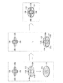
上述した切替信号発生回路56が2つのフォーカスサーボ系を切り替えるためには、テーブル21に対する加工対象物OBのセット位置を予め把握しておく必要がある。そこで、エッジ検出回路75により加工対象物OBのエッジを検出することで加工対象物OBのセット位置を把握することができる。図9は、固定治具110にセットされる加工対象物OBの配置を表す。各加工対象物OBは、テーブル21の回転軸(固定治具110の中心)を中心とした同一円周上に配置される。この実施形態においては、固定治具110に4つの加工対象物OBをセットするため、テーブル21を1回転させたときに中心から半径r1の位置において8つのエッジA(1),A(2),A(3),A(4),A(5),A(6),A(7),A(8)を検出することができる。従って、エッジA(1)〜A(8)に基づいて加工対象物OBのテーブル21に対するセット位置を計算することができる。このセット位置の計算処置については後述する。
In order for the switching
第2信号増幅回路66の出力する受光信号は、エラー検出回路76にも入力される。エラー検出回路76は、加工対象物OBの表面に形成される異常部を検出する回路であり、コントローラ90から指示を受けると作動を開始する。エラー検出回路76は、図10に示すように、設定外レベル検出回路761と設定内レベル検出回路762と遅延回路763とスイッチ回路764とを備えている。設定外レベル検出回路761は、入力した受光信号の信号レベル(波高値)が、第1基準レベルR1と、第1基準レベルR1よりも高い第2基準レベルR2との間の正常範囲(第1実施形態におけるマスク信号発生回路67の設定した正常範囲に相当する)から外れたとき、つまり、受光信号の信号レベルが第1基準レベルR1を下回ったとき、あるいは、第2基準レベルR2を上回ったとき、第2信号をスイッチ回路764に出力する。
The light reception signal output from the second
一方、設定内レベル検出回路762は、入力した受光信号の信号レベル(波高値)が、上記正常範囲から外れている状態から正常範囲内に入ったとき、つまり、受光信号の信号レベルが第1基準レベルR1を下回っている状態から第1基準レベルR1にまで増大したとき、あるいは、第2基準レベルR2を上回っている状態から第2基準レベルR2にまで低下したとき、第1信号を出力する。遅延回路763は、設定内レベル検出回路762の出力した第1信号を入力し、その第1信号を遅延量d3だけ遅延させてスイッチ回路764に出力する。この遅延量d3は、コントローラ90により遅延回路763に対して予め指示される。コントローラ90は、この遅延量d3を下記式により計算する。
d3=(DS/v)+A
DSは、加工対象物OBの表面における加工用レーザ光の照射位置と検査用レーザ光の照射位置との間隔(照射位置間隔)を表し、vは、テーブル21の回転により加工用レーザ光の照射位置が加工対象物OBの表面を移動する線速度であり、Aは、予め設定した正の微少値である。
On the other hand, the in-setting
d3 = (DS / v) + A
DS represents the interval (irradiation position interval) between the irradiation position of the processing laser beam and the irradiation position of the inspection laser beam on the surface of the processing object OB, and v represents the irradiation of the processing laser beam by the rotation of the table 21. The position is a linear velocity at which the position moves on the surface of the workpiece OB, and A is a positive fine value set in advance.
ここで、受光信号の波高値の推移と、第1信号、第2信号の出力タイミングについて図12を用いて説明する。受光信号の波高値が第1基準レベルR1と第2基準レベルR2との間に収まっているあいだは、設定外レベル検出回路761および設定内レベル検出回路762から信号が出力されない。そして、検査用レーザ光の照射位置(光スポット)が加工対象物OBの異常部に入ると、受光信号の波高値が低下し、第1基準レベルR1を下回ると(時刻t1)、設定外レベル検出回路761から第2信号(所定幅のパルス信号)が出力される。その後、検査用レーザ光の照射位置が異常部を抜け出ると受光信号の波高値が増大し、第1基準レベルR1以上になると(時刻t2)、設定内レベル検出回路762から第1信号(所定幅のパルス信号)が出力される。そして、遅延回路763は、第1信号を遅延量d3だけ遅延させたタイミング、つまり時刻t3(=t2+d3)にて第1信号を出力する。
Here, the transition of the peak value of the received light signal and the output timing of the first signal and the second signal will be described with reference to FIG. While the peak value of the received light signal falls between the first reference level R1 and the second reference level R2, no signal is output from the out-of-setting
スイッチ回路764は、設定外レベル検出回路761から出力された第2信号、および、遅延回路763から出力された第1信号の信号切替回路83への出力/遮断を切り替えるスイッチである。スイッチ回路764は、そのスイッチの開閉状態を切替信号発生回路56からの信号に応じて切り替えるように構成される。スイッチ回路764は、切替信号発生回路56から第2信号を入力した場合には、スイッチをオフ状態にして設定外レベル検出回路761および遅延回路763から信号切替回路83への信号経路を遮断する。切替信号発生回路56から出力される信号は、信号切替回路83にも入力される。従って、この場合、信号切替回路83は、切替信号発生回路56からの第2信号により第2フォーカスサーボ系回路82とドライブ回路65とを接続する。つまり、フォーカスサーボ系を第2フォーカスサーボ系に切り替える。
The
一方、切替信号発生回路56から第1信号を入力した場合には、スイッチ回路764は、スイッチをオン状態にして設定外レベル検出回路761および遅延回路763から信号切替回路83への信号経路を接続する。このため、設定外レベル検出回路761の出力する第2信号、あるいは、遅延回路763の出力する第1信号が信号切替回路83に出力される。
On the other hand, when the first signal is input from the switching
切替信号発生回路56は、加工用レーザ光の照射位置に応じて第1信号あるいは第2信号を出力するが、そのためには、加工対象物OBがテーブル21にセットされている位置を切替信号発生回路56側で予め把握しておく必要がある。そこで、作業者は、レーザ加工を行う前に、入力装置91を操作してコントローラ90によりセット位置取得ルーチンを実行させて、加工対象物OBのセット位置を切替信号発生回路56に記憶させる。以下、コントローラ90が行うセット位置取得ルーチンについて説明する。図11は、セット位置取得ルーチンを表すフローチャートである。このセット位置取得ルーチンは、コントローラ90のROM内に制御プログラムとして記憶されており、ステップS100にて開始される。尚、セット位置取得ルーチンを実施するに先だって、第1実施形態のレーザ加工ルーチンを開始するときと同様な半径位置検出回路52およびフィードモータ制御回路54に対しての初期設定が行われる。
The switching
コントローラ90は、まず、ステップS102において、フィードモータ制御回路54に対して、予め設定されたセット位置検出用半径位置への移動を指示する。これにより、フィードモータ制御回路54は、半径位置検出回路52によって検出された半径位置を入力しながら、レーザ光の照射位置がテーブルの中心から半径r1となるセット位置検出用半径位置に一致するまで、フィードモータ23の回転を制御してテーブル21を移動する。こうして、テーブル21がセット位置検出用半径位置にまで移動すると、コントローラ90は、ステップS104において、スピンドルモータ制御回路53に対して低回転速度によるスピンドルモータ22の回転開始を指示する。スピンドルモータ制御回路53は、エンコーダ22aからのA相信号およびB相信号を用いてスピンドルモータ22の回転速度を計算し、この計算した回転速度がコントローラ90から入力された低回転速度に等しくなるようにスピンドルモータ22の回転制御を開始する。
First, in step S102, the
続いて、コントローラ90は、ステップS106において、第1レーザ駆動回路71に対して非加工用レーザ光照射の開始を指示し、次に、ステップS108において、第2フォーカスサーボ系のフォーカスサーボ回路82cおよび図示しないフォーカスアクチュエータ40を駆動する回路とS字検出回路に作動開始を指示する。この場合、コントローラ90は、信号切替回路83に対して第2信号を出力して、第2フォーカスサーボ系によるフォーカスサーボを有効にする。これにより、非加工用レーザ光が加工対象物OBの表面に照射されるとともに、その焦点位置が加工対象物OBあるいは固定治具110の表面に一致するように、対物レンズ36の光軸方向の位置制御が開始される。第2フォーカスサーボ系においては、第2受光光学系のS字検出距離が長く設定され、しかも、フォーカスサーボ回路82cのカットオフ周波数も低く設定されているため、フォーカスサーボが外れない。次に、コントローラ90は、ステップS110において、第2レーザ駆動回路72に対して検査用レーザ光照射の開始を指示する。これにより、第2レーザ光源41が駆動され、加工対象物OBの表面に検査用レーザ光が照射される。
Subsequently, in step S106, the
続いて、コントローラ90は、ステップS112において、エッジ検出回路75と回転角度検出回路55とに作動開始を指示する。次に、ステップS114において、回転角度検出回路55により検出される回転角度が極小値θa以下になる(回転角度が0になる)のを待つ。そして、テーブル21の回転角度が極小値θa以下になると(S114:Yes)、コントローラ90は、ステップS116において、変数nの値を「1」に設定し、ステップS118において、エッジ検出回路75からエッジ検出信号を入力したか否かを判断する。コントローラ90は、エッジ検出信号が入力されるまで、その判断を繰り返し、エッジ検出信号が入力されると(S118:Yes)、ステップS120において、回転角度検出回路55から出力される回転角度A(n)を表すデジタルデータを取得しRAM等のメモリに一時的に記憶する。
Subsequently, in step S112, the
続いて、コントローラ90は、ステップS122において、変数nの値が「8」であるか否かを判断し、n=8でない場合には、ステップS124において、変数nの値を「1」だけインクリメントして、その処理をステップS118に戻す。従って、コントローラ90は、エッジ検出回路75から出力されるエッジ検出信号を入力するたびに、そのときのテーブル21の回転角度A(n)を表すデジタルデータを逐次記憶していく。こうして回転角度A(n)を表すデータを8つ記憶すると、変数nの値が8となり、ステップS122の判断が「Yes」となる。
Subsequently, in step S122, the
テーブル21を回転させたときにレーザ光の光スポットが各加工対象物OBの表面を横切るようにテーブル21の半径位置r1を設定した場合には、テーブル21を1回転させると、光スポットが各加工対象物OBのエッジを通過するたびにエッジ検出回路75からエッジ検出信号が出力される。このエッジ検出信号は、光スポットが1枚の加工対象物OBを通過するときに2回出力される。従って、エッジ検出信号を8回検出することで、全ての加工対象物OBのエッジを検出したことになる。
When the radial position r1 of the table 21 is set so that the light spot of the laser beam crosses the surface of each workpiece OB when the table 21 is rotated, the light spot is changed by rotating the table 21 once. An edge detection signal is output from the
コントローラ90は、ステップS122において「Yes」と判断すると、その処理をステップS126に進め、フォーカスサーボ回路82cに対してフォーカスサーボ制御の停止を指示する。続いて、ステップS128において、第2レーザ駆動回路72に対して検査用レーザ光の照射停止を指示し、ステップS130において、第1レーザ駆動回路71に対して非加工用レーザ光の照射停止を指示する。これにより、加工対象物OBへの検査用レーザ光の照射と非加工用レーザ光の照射とが停止される。続いて、コントローラ90は、ステップS132において、スピンドルモータ制御回路53に対して回転停止を指示する。これによりテーブル21の回転が停止する。続いて、ステップS134において、エッジ検出回路75と回転角度検出回路55に対して作動停止を指示する。
If the
続いて、コントローラ90は、ステップS136において、上記8つの回転角度A(1)〜A(8)に基づいて、加工対象物OBのセット位置を計算する。加工対象物OBのセット位置は、図9に示すように、テーブル21に対する加工対象物OBの配置された回転角度により表される。加工対象物OBの配置された回転角度とは、テーブル21の中心(固定治具110の中心)である原点と各加工対象物OBの中心とを結ぶライン上を、レーザ光が照射しているときのテーブル21の回転角度C(1)〜C(4)である。この回転角度C(1)〜C(4)は次式のように算出される。
C(1)=(A(1)+A(2))/2
C(2)=(A(3)+A(4))/2
C(3)=(A(5)+A(6))/2
C(4)=(A(7)+A(8))/2
Subsequently, in step S136, the
C (1) = (A (1) + A (2)) / 2
C (2) = (A (3) + A (4)) / 2
C (3) = (A (5) + A (6)) / 2
C (4) = (A (7) + A (8)) / 2
続いて、コントローラ90は、ステップS138において、回転角度C(1)〜C(4)を表すデータを切替信号発生回路56内のメモリに書き込む。これにより、切替信号発生回路56のメモリに回転角度C(1)〜C(4)を表すデータが記憶される。コントローラ90は、このステップS138処理を行うと、ステップS140にてセット位置取得ルーチンを終了する。このセット位置取得ルーチンが終了すると、その後、レーザ加工が開始される。
Subsequently, the
図13は、第2実施形態におけるレーザ加工ルーチンを表すフローチャートである。このレーザ加工ルーチンは、コントローラ90のROM内に制御プログラムとして記憶されている。作業者は、レーザ加工を実施するに当たっては、第1実施形態と同様に入力装置91を用いて加工条件等を入力してコントローラ90に記憶させる。以下、レーザ加工ルーチンについて説明するが、第1実施形態と同様な処理については簡単な説明に留める。
FIG. 13 is a flowchart showing a laser processing routine in the second embodiment. This laser processing routine is stored in the ROM of the
ステップS200によりレーザ加工ルーチンが開始されると、コントローラ90は、ステップS202において、フィードモータ制御回路54に前記入力されたレーザ加工開始半径位置に移動するように指示する。これにより、フィードモータ制御回路54がフィードモータ23を駆動制御して、テーブル21をレーザ加工開始半径位置にまで移動させる。続いて、コントローラ90は、ステップS204において、前記入力されたレーザ加工開始半径位置および回転線速度を用いて、スピンドルモータ22の回転速度を計算し、この計算した回転速度をスピンドルモータ制御回路53に出力するとともにスピンドルモータ22の回転開始を指示する。これによりスピンドルモータ22は、指示された回転速度による回転を開始する。尚、コントローラ90は、回転開始指示を出力した後は、本ルーチンとは別の割り込みルーチンにより、スピンドルモータ22の回転速度の計算を繰り返し、その都度、計算した回転速度をスピンドルモータ制御回路53に出力する。
When the laser processing routine is started in step S200, the
続いて、コントローラ90は、ステップS206において、信号切替回路83に対して第2信号を出力する。これにより、第2フォーカスサーボ系回路82がドライブ回路65と接続される。続いて、コントローラ90は、ステップS208において、第1レーザ駆動回路71に対して非加工用レーザ光の照射開始を指示する。これにより、第1レーザ駆動回路71は、第1レーザ光源31に対して、非加工レベルの駆動信号の出力を開始し、非加工用レーザ光が加工対象物OBあるいは固定治具110の表面に照射される。続いて、コントローラ90は、ステップS210において、フォーカスサーボ回路81c,82cおよび図示しないフォーカスアクチュエータ40を駆動する回路とS字検出回路に作動開始を指示する。これにより、非加工用レーザ光の焦点位置が加工対象物OBあるいは固定治具110の表面に常に一致するように、対物レンズ36の位置が光軸方向に変位する制御が開始される。この場合、信号切替回路83が第2フォーカスサーボ系回路82とドライブ回路65とを接続しているため、第2フォーカスサーボ系によるフォーカスサーボ制御が開始される。
Subsequently, the
続いて、コントローラ90は、ステップS212において、第2レーザ駆動回路72に対して検査用レーザ光の照射開始を指示する。これにより、第2レーザ駆動回路72は、第2レーザ光源41に対して、一定の検査レベルの駆動信号の出力を開始する。こうして加工対象物OBあるいは固定治具110の表面には、非加工用レーザ光の光スポットから照射位置間隔DSだけ離れた位置に検査用レーザ光の光スポットが形成され、この光スポットの反射光が第2フォトディテクタ45によって検出される。
Subsequently, in step S212, the
続いて、コントローラ90は、ステップS214において、フィードモータ制御回路54に対して、半径方向への移動開始を指示する。この場合、コントローラ90は、前記入力された回転線速度および加工ピッチ、半径位置検出回路52から取り込んだ半径位置に基づいて移動速度を計算し、フィードモータ制御回路54に対して移動速度を指示する。これにより、テーブル21は、指示された移動速度で半径方向に移動し始める。尚、コントローラ90は、半径方向への移動開始を指示した後は、本ルーチンとは別の割り込みルーチンにより、テーブル21の移動速度の計算を繰り返し、その都度、計算した移動速度をフィードモータ制御回路54に出力する。
Subsequently, in step S214, the
続いて、コントローラ90は、ステップS216において、回転角度検出回路55、切替信号発生回路56、エラー検出回路76に対して作動開始を指示する。これにより、回転角度検出回路55は、テーブル21の回転角度を表すデジタル信号を切替信号発生回路56へ出力し始める。また、切替信号発生回路56は、回転角度検出回路55により検出されたテーブル21の回転角度の入力を開始し、その回転角度に基づいて信号切替回路83に対して第1信号または第2信号を出力する処理を開始する。この切替信号発生回路56の処理は、詳しくは後述するが、加工用レーザ光が固定治具110および固定治具110と加工対象物OBとの境界部を照射するときには第2フォーカスサーボ系が選択され、加工用レーザ光が加工対象物OBを照射するときには第1フォーカスサーボ系が選択されるように、テーブル21の回転角度に応じて第1信号または第2信号を出力するものである。また、コントローラ90は、エラー検出回路76に対して作動開始を指示するとき、上述した遅延量d3(=(DS/v)+A)を計算して遅延回路763に出力する。
Subsequently, the
続いて、コントローラ90は、ステップS218において、第1レーザ駆動回路71に対して加工用レーザ光の照射開始を指示するとともに、発光信号供給回路73に信号の出力を指示する。この指示により、第1レーザ駆動回路71は、第1レーザ光源31に出力していた駆動信号を、非加工レベルから加工レベルに切り替え、発光信号供給回路73から供給される信号の波形に応じた波形にする。これにより、加工対象物OBには非加工用レーザ光に代わって加工用レーザ光が照射され、加工対象物OBのレーザ加工が開始される。
Subsequently, in step S218, the
続いて、コントローラ90は、ステップS220において、半径位置検出回路52から出力される半径位置を表すデータを取り込み、ステップS222において、加工終了半径位置に到達したか否かを判断する。加工終了半径位置は、作業者がレーザ加工を開始するにあたって入力設定した値である。ステップS220,S222の処理は、半径位置検出回路52により検出される半径位置が加工終了半径位置に一致するまで繰り返される。従って、この間は、加工用レーザ光の照射により加工対象物OBのレーザ加工が継続される。同時に、エラー検出回路76により、レーザ加工直前位置での検査用レーザ光の反射光強度に基づく異常部の検出およびフォーカスサーボ系の切替信号(第1信号または第2信号)の出力処理が行われる。また、切替信号発生回路56により、テーブル21の回転角度に応じたフォーカスサーボ系の切替信号(第1信号または第2信号)の出力処理も行われる。
Subsequently, in step S220, the
ここで、切替信号発生回路56の行うフォーカスサーボ系の切替信号の出力処理について説明する。図14は、切替信号発生回路56の行うフォーカスサーボ系切替信号出力ルーチンを表すフローチャートである。このフォーカスサーボ系切替信号出力ルーチンは、切替信号発生回路56のROM内に制御プログラムとして記憶されている。切替信号発生回路56は、コントローラ90からの作動開始の指示(図13:ステップS216)により、ステップS300にてフォーカスサーボ系切替信号出力ルーチンを開始する。
Here, the focus servo system switching signal output processing performed by the switching
切替信号発生回路56は、まず、ステップS302において、回転角度検出回路55からテーブル21の回転角度を表す信号を取り込む。続いて、ステップS304において、回転角度検出回路55により検出される回転角度が予め設定した微少値θa以下になる(回転角度が0になる)のを待って、ステップS306において、変数nの値を「1」に設定する。続いて、ステップS308において、半径位置検出回路52の出力する半径位置を表す信号を取り込む。
The switching
続いて、切替信号発生回路56は、ステップS310において、信号出力角度D(1)〜D(8)を計算する。この信号出力角度D(1)〜D(8)は、図9に示すように、加工用レーザ光の照射位置が、加工対象物OBと固定治具110との境界から僅かに加工対象物OB側となる点を通過するときのテーブル21の回転角度であり、具体的には、次式のように計算される。
D(1)=C(1)−Θ+ΔΘ
D(2)=C(1)+Θ−ΔΘ
D(3)=C(2)−Θ+ΔΘ
D(4)=C(2)+Θ−ΔΘ
D(5)=C(3)−Θ+ΔΘ
D(6)=C(3)+Θ−ΔΘ
D(7)=C(4)−Θ+ΔΘ
D(8)=C(4)+Θ−ΔΘ
Subsequently, the switching
D (1) = C (1) -Θ + ΔΘ
D (2) = C (1) + Θ−ΔΘ
D (3) = C (2) -Θ + ΔΘ
D (4) = C (2) + Θ−ΔΘ
D (5) = C (3) -Θ + ΔΘ
D (6) = C (3) + Θ−ΔΘ
D (7) = C (4) -Θ + ΔΘ
D (8) = C (4) + Θ−ΔΘ
ここで、Θは、加工対象物OBにおける加工用レーザ光の光スポットの移動軌跡(半径aの円)が加工対象物OBの境界と交差する点とテーブル21の回転中心とを結ぶラインと、加工対象物OBの中心とテーブル21の回転中心とを結ぶラインとのなす角度である。切替信号発生回路56のメモリには、テーブル21の回転中心から加工対象物OBの中心までの距離rcと、加工対象物OBの半径値rkとが記憶されている。また、テーブル21の回転中心から加工用レーザ光の照射位置までの距離aは、ステップS308にて半径位置として取り込まれている。従って、Θは、距離rc、半径値rk、距離aが既知であるため、rk2=a2+rc2―2・a・rc・cosΘという関係から計算することができる。また、ΔΘは、加工対象物OBの表面上の境界近傍となる点を特定するために予め半径位置(距離a)に対応して設定された微少角度であって切替信号発生回路56のメモリ内に記憶されている。
Here, Θ is a line connecting the point where the movement locus (circle of radius a) of the optical spot of the processing laser beam on the processing object OB intersects the boundary of the processing object OB and the rotation center of the table 21; This is the angle formed by the line connecting the center of the workpiece OB and the rotation center of the table 21. The memory of the switching
続いて、切替信号発生回路56は、ステップS312において、回転角度検出回路55からテーブル21の回転角度を表す信号を取り込む。続いて、ステップS314において、回転角度が信号出力角度D(n)以上であるかを判断する。回転角度が信号出力角度D(n)に到達していない場合には(S314:No)、ステップS316において、コントローラ90から作動停止の指令を受けたか否か判断し、作動停止指令を受けていない場合には、その処理をステップS312に戻す。切替信号発生回路56は、コントローラ90から作動停止指令を受けていないあいだ、ステップS312〜316の処理を繰り返し、テーブル21の回転角度がD(n)に到達すると(S314:Yes)、その処理をステップS318に移して、変数nの値が偶数であるか否かを判断する。変数nの値が偶数であれば、ステップS320において信号切替回路83に第2信号を出力し、変数nの値が奇数であれば、ステップS322において信号切替回路83に第1信号を出力する。
Subsequently, the switching
切替信号発生回路56は、ステップS320あるいはS322において第1信号あるいは第2信号を出力すると、次に、ステップS324において、変数nの値が「8」に達したか否かを判断する。変数nの値が「8」に達していない場合には、ステップS326において、変数nの値を「1」だけインクリメントして、その処理をステップS312に戻す。従って、切替信号発生回路56は、テーブル21の回転角度が信号出力角度D(n)に到達するたびに、変数nの値が偶数であれば第2信号を、変数nの値が奇数であれば第1信号を信号切替回路83に出力する。
When the switching
こうした処理が繰り返され、変数nの値が「8」に達すると、切替信号発生回路56は、その処理をステップS306に戻し、新たな半径位置に対応した信号出力角度D(1)〜D(8)を計算し(S308〜S310)、テーブル21の回転角度が信号出力角度D(n)に到達するたびに第1信号あるいは第2信号を信号切替回路83に出力する(S312〜S326)。そして、コントローラ90から作動停止の指令を入力すると、ステップS328において、フォーカスサーボ系切替信号出力ルーチンを終了する。
When such processing is repeated and the value of the variable n reaches “8”, the switching
このフォーカスサーボ系切替信号出力ルーチンによれば、加工用レーザ光が固定治具110を照射している状態から(例えば、図9の回転角度0)、加工用レーザ光の照射位置が加工対象物OBと固定治具110との境界を通過し加工対象物OBのエッジを所定距離過ぎたポイント(例えば、図9に示すD(1))に達すると、切替信号発生回路56から第1信号が出力される。従って、加工用レーザ光が加工対象物OBを照射し始めた後から、第1フォーカスサーボ系回路81のフォーカスサーボ信号がドライブ回路65に出力される。これにより、第1受光光学系を用いた追従性の良いフォーカスサーボ制御が行われる。
According to this focus servo system switching signal output routine, from the state in which the processing laser light irradiates the fixing jig 110 (for example, the
加工用レーザ光の照射位置が加工対象物OBの反対側のエッジの所定距離手前となるポイント(例えば、図9のD(2))に達すると、切替信号発生回路56から第2信号が出力される。従って、加工用レーザ光が加工対象物OBと固定治具110との境界を照射する手前から、第1フォーカスサーボ系回路81に代わって第2フォーカスサーボ系回路82のフォーカスサーボ信号がドライブ回路65に出力される。これにより、焦点位置の制御範囲が広くノイズに対して強いフォーカスサーボ制御が行われる。
When the irradiation position of the processing laser light reaches a point (for example, D (2) in FIG. 9) that is a predetermined distance before the edge on the opposite side of the processing object OB, the second signal is output from the switching
尚、上述したフォーカスサーボ系切替信号出力ルーチンおよび信号出力角度D(n)の計算は、図9に示すように、回転角度0(インデックス信号が入力するときのテーブル21の回転角度)のライン上に加工対象物OBが配置されていない場合についての説明である。回転角度0のライン上に加工対象物OBが配置されているか否かについては、次のように計算にて判断することができる。例えば、セット位置取得ルーチンにおいて、加工対象物OBの配置された角度C(1)〜C(4)を計算した際、次式によりB(1)を計算する。
B(1)=C(1)−sin-1(rk/rc)
計算値B(1)が負の値であれば、回転角度0のラインが加工対象物OB上に配置されていることになる。
Note that the calculation of the focus servo system switching signal output routine and the signal output angle D (n) described above is performed on the line of the rotation angle 0 (the rotation angle of the table 21 when the index signal is input) as shown in FIG. This is an explanation for a case where the processing object OB is not arranged. Whether or not the workpiece OB is arranged on the line with the
B (1) = C (1) −sin −1 (rk / rc)
If the calculated value B (1) is a negative value, a line having a rotation angle of 0 is arranged on the workpiece OB.
回転角度0のラインが加工対象物OB上に配置されている場合は、次式によりB(8)を計算する。
B(8)=C(4)+sin-1(rk/rc)
そして、計算値B(1),B(8)の中間のラインから回転角度0のラインまでの角度Θcを計算し、計算値Θcを切替信号発生回路56のメモリに記憶しておく。
When the line with the
B (8) = C (4) + sin −1 (rk / rc)
Then, the angle Θc from the intermediate line between the calculated values B (1) and B (8) to the line with the
この場合、切替信号発生回路56は、図14のフォーカスサーボ系切替信号出力ルーチンにおいて、ステップS310における信号出力角度D(1)〜D(8)の計算値に角度Θcを加算した値を新たな信号出力角度D(1)〜D(8)とし、また、ステップS312にて取り込む回転角度においても、回転角度検出回路55から得られる回転角度に角度Θcを加算するようにする。その際、角度が360°(360°に相当するパルスカウント値)以上となったときは、その角度から360°を減算すればよい。これにより、回転角度0のラインが加工対象物OB間の中間に位置するものとして処理することができる。
In this case, in the focus servo system switching signal output routine of FIG. 14, the switching
図13のレーザ加工ルーチンの説明に戻る。上述したように、ステップS218においてレーザ加工が開始され、ステップS220,S222においてテーブル21の半径位置に基づいて加工終了タイミングが判定される。こうしたレーザ加工中においては、上述したように切替信号発生回路56が作動して、テーブル21の回転角度に応じた切替信号(第1信号あるいは第2信号)を出力してフォーカスサーボ系を切り替える。この切替信号は、図10に示すようにエラー検出回路76のスイッチ回路764にも出力される。
Returning to the explanation of the laser processing routine of FIG. As described above, laser processing is started in step S218, and processing end timing is determined based on the radial position of the table 21 in steps S220 and S222. During such laser processing, the switching
スイッチ回路764は、切替信号発生回路56から第2信号を入力した場合には、スイッチをオフ状態にして設定外レベル検出回路761および遅延回路763から信号切替回路83への信号経路を遮断する。従って、スイッチ回路764は、加工用レーザ光が固定治具110、および、加工対象物OBと固定治具110との境界を照射しているときにはスイッチをオフ状態にする。検査用レーザ光は、加工用レーザ光の照射位置から加工方向(テーブル21の回転方向と反対方向)に離れた位置を照射するが、両者の照射位置間隔DSは非常に小さく、上述したΔΘに対応する照射軌跡距離に比べて無視できる。従って、検査用レーザ光が固定治具110、および、加工対象物OBと固定治具110との境界を照射しているときには、エラー検出回路76から信号切替回路83には切替信号(第1信号または第2信号)が出力されない。
When the second signal is input from the switching
また、スイッチ回路764は、切替信号発生回路56から第1信号を入力した場合には、スイッチをオン状態にして設定外レベル検出回路761および遅延回路763から信号切替回路83への信号経路を接続する。従って、スイッチ回路764は、検査用レーザ光が加工対象物OBの表面を照射しているときには、エラー検出回路76で検査した加工対象物OBの表面の検査結果に応じた切替信号を信号切替回路83に出力する。例えば、検査用レーザ光が加工対象物OBの表面を照射しているとき、検査用レーザ光の照射位置が異常部に入ると、受光信号の波高値が低下して正常範囲(第1基準レベルR1と第2基準レベルR2との間)から外れ、設定外レベル検出回路761から第2信号が出力される(図12:時刻t1)。この第2信号は、スイッチ回路764を介して信号切替回路83に出力される。このため、第1フォーカスサーボ系から第2フォーカスサーボ系に切り替わる。
In addition, when the first signal is input from the switching
一方、加工用レーザ光の光スポットは、照射位置間隔DSを線速度vで除算した時間だけ遅れて異常部に入る。このため、加工用レーザ光の反射光の強度は、図12に破線にて示すように、その時間だけ遅れて変化する。このときには、すでにS字検出距離の長い第2受光光学系を用いた第2フォーカスサーボ系に切り替えられているため、異常部により対物レンズ36と照射面との距離が大きく変動してもフォーカスサーボが外れない。
On the other hand, the light spot of the processing laser light enters the abnormal portion with a delay of the time obtained by dividing the irradiation position interval DS by the linear velocity v. For this reason, the intensity of the reflected light of the processing laser light changes with a delay by that time, as shown by the broken line in FIG. At this time, since it has been switched to the second focus servo system using the second light receiving optical system having a long S-shaped detection distance, the focus servo even if the distance between the
検査用レーザ光の照射位置が異常部が通り過ぎると受光信号の波高値が正常範囲に戻り、設定内レベル検出回路762から第1信号が遅延回路763に出力される(図12:時刻t2)。遅延回路763は、第1信号を遅延量d3だけ遅延させて信号切替回路83に出力する(図12:時刻t3)。信号切替回路83は、この第1信号を入力すると、出力する信号を第2フォーカスサーボ系による信号から第1フォーカスサーボ系による信号に切り替える。このフォーカスサーボ系が切り替わるタイミングは、加工用レーザ光の照射位置が異常部が通り抜けた後となる。従って、S字検出距離の短い第1受光光学系を用いた第1フォーカスサーボ系に切り替えられてもフォーカスサーボが外れることがなく、高精度にレーザ加工を行うことができる。
When the irradiation position of the inspection laser light passes through the abnormal part, the peak value of the received light signal returns to the normal range, and the first signal is output from the setting
こうした処理が繰り返され、ステップS222おいて、テーブル21の半径位置が加工終了半径位置に到達したと判定されると、コントローラ90は、ステップS224において、フォーカスサーボ回路81c,82cに作動停止を指示して、フォーカスサーボ制御を停止させる。次に、コントローラ90は、ステップS226において、第2レーザ駆動回路72に対して検査用レーザ光の照射停止を指示し、ステップS228において、第1レーザ駆動回路71に対して加工用レーザ光の照射停止を指示する。これにより、検査用レーザ光および加工用レーザ光の照射が停止される。続いて、コントローラ90は、ステップS230において、回転角度検出回路55、切替信号発生回路56、エラー検出回路76の作動停止の指示を行う。
When such processing is repeated and it is determined in step S222 that the radial position of the table 21 has reached the machining end radial position, the
続いて、コントローラ90は、ステップS232においてスピンドルモータ制御回路53に対して回転停止を指示し、ステップS234においてフィードモータ制御回路54に対して半径方向への移動停止を指示する。これにより、スピンドルモータ22およびフィードモータ23が停止する。こうしてテーブル21の回転と半径方向への移動が停止すると、ステップS236により本レーザ加工ルーチンが終了する。
Subsequently, the
以上説明した第2実施形態のレーザ加工装置2によれば、複数の加工対象物OBを同時にレーザ加工するため生産効率を向上させることができる。しかも、加工用レーザ光が、固定治具110および加工対象物OBと固定治具110の境界を照射している場合と、加工対象物OBを照射している場合とでフォーカスサーボ制御の形態を切り替え、前者の場合には焦点位置の制御範囲が広くカットオフ周波数の低い第2フォーカスサーボ系によるフォーカスサーボ制御を行うため、段差Δtや隙間Δxなどの外乱に対してもフォーカスサーボが外れない。また、後者の場合には、照射面の変位に対して追従性の良い第1フォーカスサーボ系によるフォーカスサーボ制御を行うため、レーザ加工の加工精度を良好に維持できる。また、加工用レーザ光を加工対象物OBに照射してレーザ加工しているときであっても、レーザ加工直前位置での検査用レーザ光の反射光から異常部を検出したときには、第2フォーカスサーボ系によるフォーカスサーボ制御に切り替え、しかも、加工用レーザ光の照射位置が異常部を通り抜けるまでは、そのフォーカスサーボ制御を維持するため、異常部によりフォーカスサーボが外れてしまうこともない。従って、正常なレーザ加工を継続することができ、加工対象物OBの損失や加工時間の無駄を低減することができる。これらの結果、生産効率を一層向上させることができる。
According to the
尚、第1フォーカスサーボ系にてフォーカスサーボ制御を行う制御モードが本発明の通常モードに相当し、異常部の検出時に第2フォーカスサーボ系にてフォーカスサーボ制御を行う制御モードが本発明の異常検出時モードに相当する。また、エラー検出回路76において設定外レベル検出回路761にて第1信号が出力されてから設定内レベル検出回路762にて第2信号が出力されるまでの期間が本発明の異常期間に相当し、設定外レベル検出回路761にて第1信号が出力されてから遅延回路763にて第2信号が出力されるまでの期間が本発明の制御モード切替期間に相当する。
The control mode in which the focus servo control is performed in the first focus servo system corresponds to the normal mode of the present invention, and the control mode in which the focus servo control is performed in the second focus servo system when an abnormal portion is detected is the abnormality of the present invention. This corresponds to the detection mode. In the
以上、本発明の実施形態について説明したが、本発明の実施にあたっては、上記実施形態に限定されるものではなく、本発明の目的を逸脱しない限りにおいて種々の変形も可能である。 The embodiments of the present invention have been described above. However, the present invention is not limited to the above-described embodiments, and various modifications can be made without departing from the object of the present invention.
例えば、第1実施形態においては、ホールド信号がハイレベルとなっている期間、フォーカスサーボ回路64にフォーカスエラー信号をゼロとして出力することによりフォーカスサーボをホールドしたが、例えば、フォーカスサーボ回路46やドライブ回路50において、ホールド信号がハイレベルになる直前の出力信号を継続させるようにしてフォーカスサーボをホールドするようにしてもよい。これによっても、第1実施形態と同様の効果が得られる。
For example, in the first embodiment, while the hold signal is at a high level, the focus servo is held by outputting the focus error signal as zero to the
また、第1実施形態においては、加工対象物OBの異常部を検出した後、遅延量d1だけ遅延させてホールド信号を出力するようにしたが、検査用レーザ光の反射光から異常部を検出した時点(図3の時刻t1)からホールド信号をハイレベルにし、異常部が検出されなくなった時点(図3の時刻t2)から、照射位置間隔DSを線速度vで除算した時間に微少時間を加算した時間(例えば、図3の遅延量d2)だけ経過したときにホールド信号をローレベルに落としてホールド解除するようにしてもよい。これによれば、回路構成が簡単になり低コスト化を図ることができる。 In the first embodiment, after detecting the abnormal part of the workpiece OB, the hold signal is output after being delayed by the delay amount d1, but the abnormal part is detected from the reflected light of the inspection laser light. The hold signal is set to the high level from the time point (time t1 in FIG. 3), and a minute time is added to the time obtained by dividing the irradiation position interval DS by the linear velocity v from the time point (time t2 in FIG. 3) when the abnormal part is not detected. When the added time (for example, the delay amount d2 in FIG. 3) elapses, the hold signal may be lowered to a low level to release the hold. According to this, the circuit configuration is simplified and the cost can be reduced.
また、本実施形態においては、加工対象物OBをセットするセット部として円盤状のテーブル21を用いているが、図15に示すように、ドラム状の固定治具121をセット部として備えたレーザ加工装置3であってもよい。このレーザ加工装置3は、固定治具121を回転可能に備えた移動ステージ140と、移動ステージ140に固定され固定治具121を回転させるスピンドルモータ122と、移動ステージ140を固定治具121の軸線方向に移動可能に支持するステージガイド141と、ステージガイド141に設けられるねじ送り機構142と、ねじ送り機構142を介して移動ステージ140を移動させるフィードモータ123と、ステージガイド141から立設されたヘッド支持フレーム143に固定される加工ヘッド130とを備えている。スピンドルモータ122、フィードモータ123、加工ヘッド130は、上記第1実施形態のスピンドルモータ22、フィードモータ23、加工ヘッド30に相当するものである。このレーザ加工装置3においては、固定治具121にシート状の加工対象物OB’を巻いてセットし、固定治具121を中心軸周りに回転させながら軸線方向に送ることで、加工ヘッド130から照射されたレーザ光(加工用レーザ光および検査用レーザ光)の照射位置を加工対象物OB’の表面全体にわたって移動させる構成を採用している。
In this embodiment, the disk-shaped table 21 is used as a set part for setting the workpiece OB. However, as shown in FIG. 15, a laser provided with a drum-shaped
また、第2実施形態においては、複数の加工対象物OBをテーブル21に同一円周上に配置して同時にレーザ加工を行うレーザ加工装置について説明したが、1枚の円盤状の加工対象物OBをテーブル21の中心にセットしてレーザ加工を行うレーザ加工装置、あるいは、1枚のシート状の加工対象物OB’をドラム状の固定治具121にセットしてレーザ加工を行うレーザ加工装置に適用することもできる。この場合、加工用レーザ光が固定治具の表面を照射しないため、フォーカスサーボ系の切替は、異常部の検出のみに基づいて行うようにすればよい。
Further, in the second embodiment, the laser processing apparatus has been described in which a plurality of processing objects OB are arranged on the same circumference on the table 21 and simultaneously perform laser processing. However, one disk-shaped processing object OB has been described. A laser processing apparatus that performs laser processing by setting the center of the table 21 or a laser processing apparatus that performs laser processing by setting a single sheet-like object OB ′ on a drum-shaped
また、本実施形態においては、加工ヘッド30とテーブル21との相対位置を変更するにあたって、テーブル21をその半径方向に移動させる構成を採用しているが、加工ヘッド30をテーブル21の半径方向に移動させる構成であってもよい。また、テーブル21と加工ヘッド30との両方を関連させて移動させるようにすることもできる。また、ドラム状の固定治具121を設けた図15に示すレーザ加工装置3の場合には、固定治具121を軸線方向に移動させずに、加工ヘッド130を固定治具121の軸線方向に移動させる構成であってもよい。これによっても、上述した実施形態と同様の効果を奏することができる。
In this embodiment, when changing the relative position between the machining
また、本実施形態においては、加工用レーザ光の照射により加工対象物OBの表面をレーザ加工するものであるが、このレーザ加工は、加工対象物OBにピットや連続した溝を直接形成する加工だけでなく、後工程において現像液の作用によりピットや連続した溝が形成される反応跡を形成するものでもよい。 In this embodiment, the surface of the workpiece OB is laser-processed by irradiating the processing laser beam. This laser processing is a process of directly forming pits or continuous grooves on the workpiece OB. In addition, a reaction trace in which pits and continuous grooves are formed by the action of a developing solution in a subsequent process may be used.
また、本実施形態においては、第2信号増幅回路66の増幅率を一定としたが、加工対象物OBの反射率が個体ごとに大きく変わる場合には、加工対象物OBの反射率に応じて増幅率を変化させ、第2信号増幅回路66が出力する信号のレベルが一定になるようにしてもよい。この場合、第2信号増幅回路66が出力する信号の高周波数成分をローパスフィルタで除去した信号を第2信号増幅回路66にフィードバックさせ、この信号の強度が一定になるように増幅率を変化させるようにすればよい。また、第2信号増幅回路66が出力する信号の異常箇所を除いた箇所の振幅を検出し、この振幅が一定になるように増幅率を変化させるようにしてもよい。これによれば、加工対象物OBの反射率が個体ごとに変わっていても第2信号増幅回路66が出力する信号のレベルは一定になるので、加工対象物OBの反射率によらず異常検出の精度を一定にすることができる。
Further, in the present embodiment, the amplification factor of the second
また、本実施形態においては、検査用レーザ光の反射光強度を第2フォトディテクタ45により検出したが、これに代えて、複数の受光領域に分割されたフォトディテクタを用いて各受光領域ごとに反射光強度を検出し、この検出した反射光強度を使った演算式により得られる演算結果に基づいて異常検出を行うようにしてもよい。例えば、検査用レーザ光の反射光を受光するフォトディテクタとして、本実施形態の第1フォトディテクタ39と同様な4分割受光素子にて構成されるフォトディテクタを使用する。そして、時計回りに配置された4つの受光領域(A,B,C,D)に入射した反射光の強度(a,b,c,d)を用いて、(a+d)−(b+c)を演算し、この演算結果である演算値と予め設定した基準値(あるいは基準範囲)とを比較することにより、異常期間を検出することもできる。この場合、異常箇所においては、S字状に信号が変化する。従って、演算値が、上下に設けた基準値を基準範囲内から基準範囲外に向かってクロスしたときから基準範囲外から基準範囲内に向かってクロスしたときまでを異常期間とするようにするとよい。これによっても、上述した実施形態と同様の効果を奏する。
In the present embodiment, the reflected light intensity of the inspection laser beam is detected by the
また、この4分割フォトディテクタの前にシリンドリカルレンズを配置して、(a+c)−(b+d)を演算し、即ちフォーカスエラー信号を作成し、この演算結果である演算値と予め設定した基準値(あるいは基準範囲)とを比較することにより、異常期間を検出することもできる。これによっても、上述した実施形態と同様の効果を奏する。 In addition, a cylindrical lens is disposed in front of the quadrant photodetector, and (a + c) − (b + d) is calculated, that is, a focus error signal is generated, and the calculated value as a result of this calculation and a preset reference value (or The abnormal period can also be detected by comparing with the reference range. This also has the same effect as the above-described embodiment.
また、微分回路を設け、検査用レーザ光の反射光の強度を時間で微分した値と、基準値(あるいは基準範囲)とを比較することにより異常期間を検出することもできる。この場合も、異常箇所においては、反射光信号を微分した微分値がS字状に変化するため、微分値が、上下に設けた基準値を基準範囲内から基準範囲外に向かってクロスしたときから基準範囲外から基準範囲内に向かってクロスしたときまでを異常期間とするようにするとよい。これによっても、上述した実施形態と同様の効果を奏する。 Also, an abnormal period can be detected by providing a differentiating circuit and comparing a value obtained by differentiating the intensity of reflected light of the inspection laser light with time and a reference value (or reference range). Also in this case, at the abnormal location, the differential value obtained by differentiating the reflected light signal changes in an S shape, so that the differential value crosses the reference value provided above and below from the reference range toward the outside of the reference range. It is preferable to set the abnormal period from the outside of the reference range to the time of crossing into the reference range. This also has the same effect as the above-described embodiment.
また、このように検査用レーザ光の反射光の強度を使った演算式により得られる演算結果に基づいて異常期間を検出する場合においても、上記のように加工対象物OBの反射率に応じて第2信号増幅回路66の増幅率を変化させれば、加工対象物OBの反射率によらず異常検出の精度を一定にすることができる。また、上記の(a+d)−(b+c),(a+c)−(b+d)の演算結果を4分割フォトディテクタの合計の信号である(a+b+c+d)で除算した信号を使用すれば、加工対象物OBの反射率によらず、演算した信号のレベルは一定になるので異常検出の精度を一定にすることができる。
Further, even when the abnormal period is detected based on the calculation result obtained by the calculation formula using the intensity of the reflected light of the inspection laser beam as described above, according to the reflectance of the workpiece OB as described above. If the amplification factor of the second
尚、本実施形態におけるテーブル21が本発明のセット部に相当し、本実施形態におけるスピンドルモータ22およびスピンドルモータ制御回路53が本発明の回転手段に相当し、本実施形態における加工ヘッド30,300が本発明の加工ヘッドに相当し、本実施形態におけるフィードモータ23およびフィードモータ制御回路54が本発明の送り手段に相当する。また、本実施形態における第1レーザ駆動回路71およびレーザ加工ルーチンを実行するコントローラ90の機能部が本発明のレーザ加工制御手段に相当し、本実施形態における第1受光光学系,第1信号増幅回路61,フォーカスエラー信号生成回路62,フォーカスサーボ回路64,ドライブ回路65,フォーカスアクチュエータ40,第2受光光学系,第1フォーカスサーボ系回路81,第2フォーカスサーボ系回路82が本発明のフォーカスサーボ手段に相当する。本実施形態における第1レーザ光源31が本発明の加工用レーザ光源に相当し、本実施形態における第2レーザ光源41が本発明の検査用レーザ光源に相当する。また、本実施形態における第2レーザ駆動回路72およびレーザ加工ルーチンにおいて検査用レーザ光を照射する処理(S18,S212)を行うコントローラ90の機能部が本発明の検査用レーザ光照射制御手段に相当し、本実施形態における第2フォトディテクタ45が本発明の光検出手段に相当し、本実施形態におけるマスク信号発生回路67,エラー検出回路76が本発明の異常期間検出手段に相当し、本実施形態における遅延回路68,エラー検出回路76が本発明の切替期間設定手段に相当し、本実施形態における導通回路63,信号切替回路83が本発明の制御モード切替手段に相当する。また、本実施形態における第1遅延回路681が本発明の第1遅延手段に相当し、本実施形態における第2遅延回路682が本発明の第2遅延手段に相当する。また、本実施形態におけるエッジ検出回路75およびセット位置取得ルーチンを実行するコントローラ90の機能部が本発明の境界検出手段に相当する。また、本実施形態における切替信号発生回路56が本発明の加工対象物非照射時制御モード切替手段に相当する。
The table 21 in the present embodiment corresponds to the set unit of the present invention, the
また、本実施形態におけるレーザ加工ルーチンが本発明の照射ステップに相当し、本実施形態におけるレーザ加工ルーチンにおいてステップS22あるいはS210にて開始される処理が本発明のフォーカスサーボ制御ステップに相当し、本実施形態のレーザ加工ルーチンにおいてステップS20あるいはS216にて開始されるマスク信号発生回路67の処理あるいはエラー検出回路76の処理が本発明の異常期間検出ステップに相当し、本実施形態のレーザ加工ルーチンにおいてステップS20あるいはS216にて開始される遅延回路68の処理あるいはエラー検出回路76により信号切替回路83を切り替える処理が本発明の制御モード切替ステップに相当する。
Further, the laser processing routine in the present embodiment corresponds to the irradiation step of the present invention, and the processing started in step S22 or S210 in the laser processing routine in the present embodiment corresponds to the focus servo control step of the present invention. In the laser processing routine of the embodiment, the processing of the mask
1,2,3…レーザ加工装置、21…テーブル、22,122…スピンドルモータ、22a…エンコーダ、23,123…フィードモータ、23a…エンコーダ、30,130,300…加工ヘッド、31…第1レーザ光源、39…第1フォトディテクタ、36…対物レンズ、40…フォーカスアクチュエータ、41…第2レーザ光源、45…第2フォトディテクタ、49…第3フォトディテクタ、52…半径位置検出回路、53…スピンドルモータ制御回路、54…フィードモータ制御回路、55…回転角度検出回路、62,81b,82b…フォーカスエラー信号生成回路、63…導通回路、64,81c,82c…フォーカスサーボ回路、65…ドライブ回路、67…マスク信号発生回路、68…遅延回路、681…第1遅延回路、682…第2遅延回路、683…フリップフロップ回路、71…第1レーザ駆動回路、72…第2レーザ駆動回路、75…エッジ検出回路、76…エラー判定回路、81…第1フォーカスサーボ系回路、82…第2フォーカスサーボ系回路、83…信号切替回路、90…コントローラ、91…入力装置、92…表示装置、110,121…固定治具、110h…固定円孔、140…移動ステージ、141…ステージガイド、OB,OB’…加工対象物。
DESCRIPTION OF
Claims (10)
前記セット部を回転させる回転手段と、
加工用レーザ光源を有し、その加工用レーザ光源から出射された加工用レーザ光を対物レンズにより集光して前記加工対象物に照射する加工ヘッドと、
前記加工用レーザ光の照射位置が、前記加工対象物の表面上を、前記セット部の回転により形成される照射移動軌跡に対して直交する方向に移動するように、前記セット部と前記加工ヘッドとの相対位置を変更する送り手段と、
前記回転手段と前記送り手段との作動を制御しつつ、前記加工用レーザ光源に駆動信号を出力して前記加工対象物の表面に前記加工用レーザ光を照射することにより、前記加工対象物の表面をレーザ加工するレーザ加工制御手段と、
前記加工用レーザ光の前記加工対象物からの反射光に基づいて、前記加工用レーザ光の焦点位置が前記加工対象物の表面と一致するように前記対物レンズを前記加工用レーザ光の光軸方向に駆動してフォーカスサーボ制御を行うフォーカスサーボ手段と
を備えたレーザ加工装置において、
前記加工ヘッドは、前記加工用レーザ光が前記加工対象物に照射される位置よりも前記回転手段の回転方向と反対側となるレーザ加工直前位置を照射する検査用レーザ光源を有し、
前記レーザ加工制御手段によりレーザ加工を行っているときに、前記検査用レーザ光源に駆動信号を出力して、前記加工対象物の表面がレーザ加工されない強度の検査用レーザ光を前記検査用レーザ光源から出射させる検査用レーザ光照射制御手段と、
前記加工対象物の表面に照射した前記検査用レーザ光の反射光の強度を検出する光検出手段と、
前記光検出手段により検出した反射光の強度に基づいて、前記検査用レーザ光の反射光の状態が正常範囲から外れている異常期間を検出する異常期間検出手段と、
前記異常期間検出手段により検出された異常期間に基づいて、前記異常期間の終了時期よりも遅い終了時期が設定された制御モード切替期間を設定する切替期間設定手段と、
前記切替期間設定手段により設定された制御モード切替期間のあいだ、前記フォーカスサーボ手段の制御モードを通常モードから異常検出時モードに切り替えて、前記対物レンズの位置を保持する、あるいは、通常モードよりも前記加工用レーザ光の焦点位置の制御範囲の広いフォーカスサーボ制御を行うようにする制御モード切替手段と
を備えたことを特徴とするレーザ加工装置。 A set part for setting a workpiece;
Rotating means for rotating the set unit;
A processing head having a processing laser light source, condensing the processing laser light emitted from the processing laser light source by an objective lens and irradiating the processing object;
The set unit and the processing head so that the irradiation position of the processing laser light moves on the surface of the processing object in a direction orthogonal to an irradiation movement locus formed by rotation of the set unit. A feeding means for changing the relative position with
While controlling the operation of the rotating means and the feeding means, by outputting a drive signal to the processing laser light source and irradiating the processing laser light on the surface of the processing object, Laser processing control means for laser processing the surface;
Based on the reflected light of the machining laser beam from the workpiece, the objective lens is placed on the optical axis of the machining laser beam so that the focal position of the machining laser beam coincides with the surface of the workpiece. In a laser processing apparatus equipped with a focus servo means that performs focus servo control by driving in a direction,
The processing head includes an inspection laser light source that irradiates a position immediately before laser processing that is opposite to the rotation direction of the rotating unit with respect to the processing object irradiated with the processing laser light.
When laser processing is performed by the laser processing control means, a driving signal is output to the inspection laser light source, and an inspection laser light having an intensity that does not cause laser processing on the surface of the processing object is generated. Laser light irradiation control means for inspection to be emitted from,
A light detection means for detecting the intensity of reflected light of the inspection laser light irradiated on the surface of the workpiece;
Based on the intensity of the reflected light detected by the light detecting means, an abnormal period detecting means for detecting an abnormal period in which the state of the reflected light of the inspection laser light is out of a normal range;
A switching period setting unit that sets a control mode switching period in which an end time later than the end time of the abnormal period is set based on the abnormal period detected by the abnormal period detection unit;
During the control mode switching period set by the switching period setting means, the control mode of the focus servo means is switched from the normal mode to the abnormality detection mode, and the position of the objective lens is maintained, or more than in the normal mode. A laser processing apparatus, comprising: control mode switching means for performing focus servo control with a wide control range of a focal position of the processing laser beam.
前記制御モード切替期間の開始時期を、前記異常期間の開始時期に対して前記理論遅れ時間より短い第1遅延時間だけ遅延させる第1遅延手段と、
前記制御モード切替期間の終了時期を、前記異常期間の終了時期に対して前記理論遅れ時間より長い第2遅延時間だけ遅延させる第2遅延手段と
を備えたことを特徴とする請求項2記載のレーザ加工装置。 The switching period setting means includes
First delay means for delaying the start time of the control mode switching period by a first delay time shorter than the theoretical delay time with respect to the start time of the abnormal period;
3. The second delay means for delaying the end time of the control mode switching period by a second delay time longer than the theoretical delay time with respect to the end time of the abnormal period. Laser processing equipment.
前記加工用レーザ光の前記加工対象物からの反射光を第1受光光学系にて受光して、その受光信号から焦点位置のずれを表すフォーカスエラー信号を生成し、前記フォーカスエラー信号に基づいて前記加工用レーザ光の焦点位置が前記加工対象物の表面と一致するように前記対物レンズを前記加工用レーザ光の光軸方向に駆動する第1フォーカスサーボ系と、
前記加工用レーザ光の前記加工対象物からの反射光を第2受光光学系にて受光して、その受光信号から焦点位置のずれを表すフォーカスエラー信号を生成し、前記フォーカスエラー信号に基づいて前記加工用レーザ光の焦点位置が前記加工対象物の表面と一致するように前記対物レンズを前記加工用レーザ光の光軸方向に駆動するフォーカスサーボ系であって、前記第1ファーストサーボ系よりも焦点位置の制御範囲の広い第2フォーカスサーボ系と
を選択可能に備え、
前記制御モード切替手段は、前記フォーカスサーボ手段に対して、前記制御モード切替期間のあいだ前記第1フォーカスサーボ系に代えて前記第2フォーカスサーボ系を作動させる指示を出力することを特徴とする請求項1ないし請求項3の何れか一項記載のレーザ加工装置。 The focus servo means includes
Reflected light of the processing laser beam from the object to be processed is received by a first light receiving optical system, and a focus error signal indicating a focus position deviation is generated from the received light signal. Based on the focus error signal A first focus servo system for driving the objective lens in the optical axis direction of the processing laser beam so that a focal position of the processing laser beam coincides with a surface of the processing target;
Reflected light of the laser beam for processing from the object to be processed is received by a second light receiving optical system, and a focus error signal indicating a focus position shift is generated from the received light signal. Based on the focus error signal A focus servo system for driving the objective lens in the optical axis direction of the processing laser beam so that a focal position of the processing laser beam coincides with a surface of the processing target; from the first first servo system; Can be selected with the second focus servo system with a wide focal position control range,
The control mode switching means outputs an instruction to operate the second focus servo system instead of the first focus servo system during the control mode switching period to the focus servo means. The laser processing apparatus according to any one of claims 1 to 3.
前記フォーカスサーボ手段は、前記加工用レーザ光が前記加工対象物を照射していないときにおいても、その照射面からの反射光に基づいて、前記加工用レーザ光の焦点位置が前記照射面と一致するように前記対物レンズを前記加工用レーザ光の光軸方向に駆動するものであり、
前記固定円孔に挿入固定された加工対象物の外周と前記固定円孔との境界を検出する境界検出手段と、
前記境界検出手段により検出した境界に基づいて、前記加工用レーザ光が前記境界を含めて前記固定治具表面を照射するときには、前記フォーカスサーボ手段に対して、前記第2フォーカスサーボ系を作動させる指示を出力する加工対象物非照射時制御モード切替手段と
を備えたことを特徴とする請求項5記載のレーザ加工装置。 The set unit arranges a plurality of workpieces on the same plane via a plate-like fixing jig in which a plurality of fixing circular holes for inserting and fixing a disk-like workpiece in the thickness direction are formed. Are fixed,
The focus servo means is configured such that, even when the processing laser beam is not irradiating the workpiece, the focus position of the processing laser beam coincides with the irradiation surface based on the reflected light from the irradiation surface. The objective lens is driven in the optical axis direction of the laser beam for processing so as to
Boundary detection means for detecting a boundary between the outer periphery of the workpiece inserted and fixed in the fixed circular hole and the fixed circular hole;
Based on the boundary detected by the boundary detection means, when the processing laser light irradiates the surface of the fixing jig including the boundary, the second servo servo system is operated with respect to the focus servo means. The laser processing apparatus according to claim 5, further comprising: a control mode switching unit that outputs an instruction when the workpiece is not irradiated.
前記セット部を回転させる回転手段と、
前記加工対象物に加工用レーザ光を対物レンズにより集光して照射する加工ヘッドと、
前記加工用レーザ光の照射位置が、前記加工対象物の表面上を、前記セット部の回転により形成される照射移動軌跡に対して直交する方向に移動するように、前記セット部と前記加工ヘッドとの相対位置を変更する送り手段と、
前記加工用レーザ光の前記加工対象物からの反射光に基づいて、前記加工用レーザ光の焦点位置が前記加工対象物の表面と一致するように前記対物レンズを前記加工用レーザ光の光軸方向に駆動してフォーカスサーボ制御を行うフォーカスサーボ手段と
を備えたレーザ加工装置に適用されるレーザ加工方法において、
前記回転手段と送り手段との作動を制御しつつ、前記加工ヘッドから前記加工対象物の表面に加工用レーザ光を照射することにより前記加工対象物の表面をレーザ加工するとともに、前記加工用レーザ光が前記加工対象物に照射される位置よりも前記回転手段の回転方向と反対側となるレーザ加工直前位置に前記加工対象物の表面がレーザ加工されない強度の検査用レーザ光を照射する照射ステップと、
前記照射ステップを行っているときに、前記フォーカスサーボ手段により、前記加工用レーザ光の焦点位置が前記加工対象物の表面と一致するように前記対物レンズを前記加工用レーザ光の光軸方向に駆動するフォーカスサーボ制御ステップと、
前記照射ステップを行っているときに、前記加工対象物の表面に照射した前記検査用レーザ光の反射光の強度を検出し、検出した反射光の強度に基づいて、前記検査用レーザ光の反射光の状態が正常範囲から外れている異常期間を検出する異常期間検出ステップと、
前記異常期間検出ステップにより検出された異常期間に基づいて、前記異常期間の終了時期よりも遅い終了時期が設定された制御モード切替期間を設定し、前記制御モード切替期間のあいだ、前記フォーカスサーボ制御ステップにおける制御モードを通常モードから異常検出時モードに切り替えて、前記対物レンズの位置を保持する、あるいは、通常モードよりも前記加工用レーザ光の焦点位置の制御範囲の広いフォーカスサーボ制御を行うようにする制御モード切替ステップと
を含むことを特徴とするレーザ加工方法。 A set part for setting a workpiece;
Rotating means for rotating the set unit;
A processing head for condensing and irradiating the processing object with a processing laser beam by an objective lens;
The set unit and the processing head so that the irradiation position of the processing laser light moves on the surface of the processing object in a direction orthogonal to an irradiation movement locus formed by rotation of the set unit. A feeding means for changing the relative position with
Based on the reflected light of the machining laser beam from the workpiece, the objective lens is placed on the optical axis of the machining laser beam so that the focal position of the machining laser beam coincides with the surface of the workpiece. In a laser processing method applied to a laser processing apparatus provided with a focus servo means that performs focus servo control by driving in a direction,
While controlling the operation of the rotating means and the feeding means, the processing head irradiates the processing laser light onto the surface of the processing object from the processing head to laser-process the surface of the processing object, and the processing laser Irradiation step of irradiating an inspection laser beam having a strength at which the surface of the object to be processed is not laser-processed at a position immediately before laser processing that is opposite to the rotation direction of the rotating means from the position at which the object is irradiated with light When,
When performing the irradiation step, the focus servo means moves the objective lens in the optical axis direction of the processing laser light so that the focal position of the processing laser light coincides with the surface of the processing object. A focus servo control step to drive,
When performing the irradiation step, the intensity of the reflected light of the inspection laser light irradiated on the surface of the workpiece is detected, and the reflection of the inspection laser light is based on the detected intensity of the reflected light. An abnormal period detection step for detecting an abnormal period in which the light state is out of the normal range;
Based on the abnormal period detected by the abnormal period detection step, a control mode switching period in which an end time later than the end time of the abnormal period is set is set, and the focus servo control is performed during the control mode switching period. The control mode in the step is switched from the normal mode to the abnormality detection mode to hold the position of the objective lens, or to perform focus servo control with a wider control range of the focus position of the processing laser light than in the normal mode And a control mode switching step.
前記加工用レーザ光の前記加工対象物からの反射光を第1受光光学系にて受光して、その受光信号から焦点位置のずれを表すフォーカスエラー信号を生成し、前記フォーカスエラー信号に基づいて前記加工用レーザ光の焦点位置が前記加工対象物の表面と一致するように前記対物レンズを前記加工用レーザ光の光軸方向に駆動する第1フォーカスサーボ系と、
前記加工用レーザ光の前記加工対象物からの反射光を第2受光光学系にて受光して、その受光信号から焦点位置のずれを表すフォーカスエラー信号を生成し、前記フォーカスエラー信号に基づいて前記加工用レーザ光の焦点位置が前記加工対象物の表面と一致するように前記対物レンズを前記加工用レーザ光の光軸方向に駆動するフォーカスサーボ系であって、前記第1ファーストサーボ系よりも焦点位置の制御範囲の広い第2フォーカスサーボ系と
を選択可能に備え、
前記制御モード切替ステップは、前記フォーカスサーボ手段に対して、前記制御モード切替期間のあいだ前記第1フォーカスサーボ系に代えて前記第2フォーカスサーボ系を作動させる指示を出力することを特徴とする請求項8記載のレーザ加工方法。 The focus servo means includes
Reflected light of the processing laser beam from the object to be processed is received by a first light receiving optical system, and a focus error signal indicating a focus position deviation is generated from the received light signal. Based on the focus error signal A first focus servo system for driving the objective lens in the optical axis direction of the processing laser beam so that a focal position of the processing laser beam coincides with a surface of the processing target;
Reflected light of the laser beam for processing from the object to be processed is received by a second light receiving optical system, and a focus error signal indicating a focus position shift is generated from the received light signal. Based on the focus error signal A focus servo system for driving the objective lens in the optical axis direction of the processing laser beam so that a focal position of the processing laser beam coincides with a surface of the processing target; from the first first servo system; Can be selected with the second focus servo system with a wide focal position control range,
The control mode switching step outputs an instruction to operate the second focus servo system instead of the first focus servo system during the control mode switching period to the focus servo means. Item 9. A laser processing method according to Item 8.
Priority Applications (1)
| Application Number | Priority Date | Filing Date | Title |
|---|---|---|---|
| JP2008210290A JP5181919B2 (en) | 2008-08-19 | 2008-08-19 | Laser processing apparatus and laser processing method |
Applications Claiming Priority (1)
| Application Number | Priority Date | Filing Date | Title |
|---|---|---|---|
| JP2008210290A JP5181919B2 (en) | 2008-08-19 | 2008-08-19 | Laser processing apparatus and laser processing method |
Publications (2)
| Publication Number | Publication Date |
|---|---|
| JP2010046669A true JP2010046669A (en) | 2010-03-04 |
| JP5181919B2 JP5181919B2 (en) | 2013-04-10 |
Family
ID=42064216
Family Applications (1)
| Application Number | Title | Priority Date | Filing Date |
|---|---|---|---|
| JP2008210290A Expired - Fee Related JP5181919B2 (en) | 2008-08-19 | 2008-08-19 | Laser processing apparatus and laser processing method |
Country Status (1)
| Country | Link |
|---|---|
| JP (1) | JP5181919B2 (en) |
Cited By (2)
| Publication number | Priority date | Publication date | Assignee | Title |
|---|---|---|---|---|
| JP2012055929A (en) * | 2010-09-08 | 2012-03-22 | Pulstec Industrial Co Ltd | Laser beam machining device and focus servo controlling method for laser beam machining device |
| CN115044757A (en) * | 2022-06-22 | 2022-09-13 | 首钢智新迁安电磁材料有限公司 | Automatic adjusting device for laser scoring parabolic lens focus |
Citations (7)
| Publication number | Priority date | Publication date | Assignee | Title |
|---|---|---|---|---|
| JPH05185263A (en) * | 1992-01-16 | 1993-07-27 | Murata Mach Ltd | Device for controlling copying in laser beam machine |
| JPH06190578A (en) * | 1992-12-25 | 1994-07-12 | Isuzu Motors Ltd | Laser beam machine |
| JPH08206862A (en) * | 1995-01-31 | 1996-08-13 | Mitsubishi Electric Corp | Method and device for laser beam machining |
| JP2003136260A (en) * | 2001-10-31 | 2003-05-14 | Sunx Ltd | Laser marking device |
| JP2007216263A (en) * | 2006-02-16 | 2007-08-30 | National Institute Of Advanced Industrial & Technology | Laser beam machining device and machining method therefor |
| JP2008093723A (en) * | 2006-10-13 | 2008-04-24 | Pulstec Industrial Co Ltd | Laser beam fine machining apparatus |
| JP2008200745A (en) * | 2007-02-22 | 2008-09-04 | Pulstec Industrial Co Ltd | Laser micromachining apparatus and its focus servo method |
-
2008
- 2008-08-19 JP JP2008210290A patent/JP5181919B2/en not_active Expired - Fee Related
Patent Citations (7)
| Publication number | Priority date | Publication date | Assignee | Title |
|---|---|---|---|---|
| JPH05185263A (en) * | 1992-01-16 | 1993-07-27 | Murata Mach Ltd | Device for controlling copying in laser beam machine |
| JPH06190578A (en) * | 1992-12-25 | 1994-07-12 | Isuzu Motors Ltd | Laser beam machine |
| JPH08206862A (en) * | 1995-01-31 | 1996-08-13 | Mitsubishi Electric Corp | Method and device for laser beam machining |
| JP2003136260A (en) * | 2001-10-31 | 2003-05-14 | Sunx Ltd | Laser marking device |
| JP2007216263A (en) * | 2006-02-16 | 2007-08-30 | National Institute Of Advanced Industrial & Technology | Laser beam machining device and machining method therefor |
| JP2008093723A (en) * | 2006-10-13 | 2008-04-24 | Pulstec Industrial Co Ltd | Laser beam fine machining apparatus |
| JP2008200745A (en) * | 2007-02-22 | 2008-09-04 | Pulstec Industrial Co Ltd | Laser micromachining apparatus and its focus servo method |
Cited By (3)
| Publication number | Priority date | Publication date | Assignee | Title |
|---|---|---|---|---|
| JP2012055929A (en) * | 2010-09-08 | 2012-03-22 | Pulstec Industrial Co Ltd | Laser beam machining device and focus servo controlling method for laser beam machining device |
| CN115044757A (en) * | 2022-06-22 | 2022-09-13 | 首钢智新迁安电磁材料有限公司 | Automatic adjusting device for laser scoring parabolic lens focus |
| CN115044757B (en) * | 2022-06-22 | 2024-01-02 | 首钢智新迁安电磁材料有限公司 | Automatic adjusting device for focus of parabolic mirror for laser scoring |
Also Published As
| Publication number | Publication date |
|---|---|
| JP5181919B2 (en) | 2013-04-10 |
Similar Documents
| Publication | Publication Date | Title |
|---|---|---|
| KR20140085562A (en) | Device and method for producing a guide bevel on a workpiece, in particular on a cutting tool, using cnc-controlled laser and clamping devices | |
| JP5018676B2 (en) | Laser processing apparatus and laser processing method | |
| JP5131957B2 (en) | Laser micromachining device and focus servo method for laser micromachining device | |
| JP5181919B2 (en) | Laser processing apparatus and laser processing method | |
| JP2006218535A (en) | Laser machining method and laser machining apparatus | |
| JP2000271772A (en) | Method and machine for laser beam machining | |
| JP2008290090A (en) | Apparatus for laser microfabrication and focus servo method therefor | |
| JP5011939B2 (en) | Laser fine processing equipment | |
| JP5136541B2 (en) | Laser processing equipment | |
| JP5644368B2 (en) | Laser processing apparatus and laser irradiation position control method for laser processing apparatus | |
| JP2011115806A (en) | Laser processing apparatus | |
| JP2011092957A (en) | Laser beam machining apparatus | |
| JP4962508B2 (en) | Laser processing apparatus and pulse signal output method for laser driving in laser processing apparatus | |
| JP5353844B2 (en) | Laser processing apparatus and focus servo control method of laser processing apparatus | |
| JP2013035057A (en) | Laser beam machine and method of controlling the same | |
| JP2009255150A (en) | Laser machining apparatus and laser machining method | |
| JP6487413B2 (en) | Laser processing head and laser processing system including the same | |
| JP7460199B2 (en) | Processing equipment and processing end detection method | |
| JP2011056561A (en) | Device and method for laser beam machining | |
| JP4911050B2 (en) | Laser processing apparatus and laser processing method | |
| CN110919168A (en) | Laser processing system and laser processing method | |
| KR20060098473A (en) | Method for controlling the laser beam in a laser processing apparatus | |
| JP5217930B2 (en) | Laser processing method and laser processing apparatus | |
| JP2007018650A (en) | Optical disk drive and method for controlling optical disk drive | |
| JP2009164406A (en) | Forming method of pit for substrate |
Legal Events
| Date | Code | Title | Description |
|---|---|---|---|
| A621 | Written request for application examination |
Free format text: JAPANESE INTERMEDIATE CODE: A621 Effective date: 20110802 |
|
| A521 | Written amendment |
Free format text: JAPANESE INTERMEDIATE CODE: A523 Effective date: 20120718 |
|
| A977 | Report on retrieval |
Free format text: JAPANESE INTERMEDIATE CODE: A971007 Effective date: 20121212 |
|
| TRDD | Decision of grant or rejection written | ||
| A01 | Written decision to grant a patent or to grant a registration (utility model) |
Free format text: JAPANESE INTERMEDIATE CODE: A01 Effective date: 20121218 |
|
| A61 | First payment of annual fees (during grant procedure) |
Free format text: JAPANESE INTERMEDIATE CODE: A61 Effective date: 20121231 |
|
| R150 | Certificate of patent or registration of utility model |
Free format text: JAPANESE INTERMEDIATE CODE: R150 |
|
| FPAY | Renewal fee payment (event date is renewal date of database) |
Free format text: PAYMENT UNTIL: 20160125 Year of fee payment: 3 |
|
| LAPS | Cancellation because of no payment of annual fees |