JP2010044930A - Arc resistant insulating material and circuit breaker - Google Patents
Arc resistant insulating material and circuit breaker Download PDFInfo
- Publication number
- JP2010044930A JP2010044930A JP2008207604A JP2008207604A JP2010044930A JP 2010044930 A JP2010044930 A JP 2010044930A JP 2008207604 A JP2008207604 A JP 2008207604A JP 2008207604 A JP2008207604 A JP 2008207604A JP 2010044930 A JP2010044930 A JP 2010044930A
- Authority
- JP
- Japan
- Prior art keywords
- arc
- ultraviolet shielding
- shielding material
- resistant
- sample
- Prior art date
- Legal status (The legal status is an assumption and is not a legal conclusion. Google has not performed a legal analysis and makes no representation as to the accuracy of the status listed.)
- Granted
Links
Images

Landscapes
- Circuit Breakers (AREA)
Abstract
Description
本発明は、耐アーク性に優れた絶縁物に関し、特に、電極と電極の間にアークが発生する遮断器等に使用することが好適な耐アーク性絶縁物およびこの耐アーク性絶縁物からなるノズルを備えた遮断器に関する。 The present invention relates to an insulator having excellent arc resistance, and particularly comprises an arc-resistant insulator suitable for use in a circuit breaker in which an arc is generated between electrodes and the arc-resistant insulator. The present invention relates to a circuit breaker provided with a nozzle.
例えば、遮断器やアークシュートブレーカのように、装置中の電極間でアークが発生する装置がある。発生したアークを、遮断器では、例えば、電極間に六フッ化硫黄ガス(SF6ガス)を吹き付けて消したり、アークシュートブレーカでは、例えば、電極両側に設置したコイルによって磁界を与え、アークシュートという領域に六フッ化硫黄ガスを吹き込んで消したりしている。また、これらの装置では、発生したアーク近傍に絶縁物を設置し、アークの熱や紫外線を多量に含む光から、装置の構成部分を保護している。 For example, there is a device that generates an arc between electrodes in the device, such as a circuit breaker or an arc chute breaker. The generated arc is extinguished by, for example, blowing a sulfur hexafluoride gas (SF 6 gas) between the electrodes in the circuit breaker, or the arc chute breaker is applied with a magnetic field by, for example, coils installed on both sides of the electrode. It is turned off by blowing sulfur hexafluoride gas into the area. In these devices, an insulator is installed in the vicinity of the generated arc to protect the components of the device from the heat of the arc and the light containing a large amount of ultraviolet rays.
従来、このような遮へい用の絶縁物として、他の物質からなる充填材を含有しない、無充填のフッ素系樹脂が使用されている。しかし、無充填のフッ素系樹脂を用いた場合、遮断時のアークで発生する多量の紫外線により、フッ素樹脂の内部で樹脂が分解し、導電性を有する炭化物が生成する。そのため、電気的な絶縁性能が著しく低下するという問題があった。 Conventionally, unfilled fluorine-based resins that do not contain fillers made of other substances have been used as such shielding insulators. However, when an unfilled fluororesin is used, the resin is decomposed inside the fluororesin due to a large amount of ultraviolet rays generated by an arc at the time of interruption, and conductive carbides are generated. For this reason, there is a problem that the electrical insulation performance is remarkably lowered.
また、樹脂の内部炭化により発生したガスが、樹脂の内部から樹脂表面に向かって噴出し、フッ素系樹脂が吹き飛ばされるという現象が起き、樹脂の表面に著しい凸凹が形成され、遮へい用に設置した絶縁物の機械的強度が大幅に低下するといった問題があった。 In addition, the phenomenon that the gas generated by the internal carbonization of the resin is ejected from the inside of the resin toward the resin surface and the fluorine-based resin is blown off occurs, and a remarkable unevenness is formed on the resin surface, which is installed for shielding. There has been a problem that the mechanical strength of the insulator is greatly reduced.
このような問題に対して、フッ素樹脂に窒化ホウ素(BN)を充填することにより、アークからの光を反射して樹脂内部への光の進入を防ぎ、内部劣化を防ぐ技術が開示されている(例えば、特許文献1参照。)。このフッ素樹脂には、窒化ホウ素(BN)が1重量%〜10重量%充填されている。 To solve such problems, a technology is disclosed in which boron nitride (BN) is filled in a fluororesin to reflect light from the arc and prevent light from entering the resin, thereby preventing internal deterioration. (For example, refer to Patent Document 1). This fluororesin is filled with 1% to 10% by weight of boron nitride (BN).
また、高分子絶縁物に、粒径が1μm以下の無機顔料および/または粒径が0.5μm以下の有機顔料を0.2〜5重量%添加する技術が開示されている(例えば、特許文献2参照。)。特許文献2では、例えば、300℃前後での焼成を必要とするポリ四フッ化エチレン樹脂に、百数十度の耐熱性を有する有機顔料や300℃以上の温度で徐々に変色する群青等を充填することが示されている。
しかしながら、上記した従来の窒化ホウ素が充填されたフッ素樹脂では、窒化ホウ素が高い熱伝導率を有することから、窒化ホウ素を充填したフッ素系樹脂の熱伝導率が高くなり、アーク熱の熱伝導範囲が拡大し、フッ素系樹脂の損耗が増加するという問題があった。 However, in the conventional fluororesin filled with boron nitride, since boron nitride has high thermal conductivity, the thermal conductivity of fluororesin filled with boron nitride is increased, and the heat conduction range of arc heat. However, there is a problem that the wear of the fluorine-based resin increases.
また、上記した従来の無機顔料を含有した高分子絶縁物では、無機顔料が、紫外光だけではく、本来遮へいする必要性が低い可視光を吸収するため、その分温度が上昇して材料の損耗が増加するといった問題があった。 In addition, in the polymer insulator containing the conventional inorganic pigment described above, the inorganic pigment absorbs not only ultraviolet light but also visible light which is originally not required to be shielded. There was a problem that wear increased.
このように、遮断器等に用いられている従来の絶縁物では、絶縁性能や耐アーク性能の低下を防止しつつ、遮断後の損耗量を低減することは困難であった。 Thus, it has been difficult for conventional insulators used in circuit breakers and the like to reduce the amount of wear after breaking while preventing deterioration in insulation performance and arc resistance performance.
そこで、本発明は、上記課題を解決するためになされたものであり、アークによる内部劣化を防止することができるとともに、損耗を防止することができる耐アーク性絶縁物およびこの耐アーク性絶縁物からなるノズルを備える遮断器を提供することを目的とする。 Accordingly, the present invention has been made to solve the above-described problems, and is capable of preventing internal deterioration due to an arc and can prevent wear, and the arc-resistant insulator. It aims at providing the circuit breaker provided with the nozzle which consists of.
上記目的を達成するために、本発明の一態様によれば、電極と電極の間に発生するアークの近傍に配置する耐アーク性絶縁物であって、所定のフッ素系樹脂に、前記フッ素系樹脂の焼成で変色しない耐熱性を有する白色系無機物で被覆された、前記フッ素系樹脂の焼成で変色しない耐熱性を有する無機紫外線遮へい材を前記フッ素系樹脂の重量の0.1〜1%含有してなることを特徴とする耐アーク性絶縁物が提供される。 In order to achieve the above object, according to one aspect of the present invention, there is provided an arc-resistant insulator disposed in the vicinity of an arc generated between electrodes, wherein the fluorine-based resin is bonded to a predetermined fluorine-based resin. 0.1 to 1% of the weight of the fluororesin containing an inorganic ultraviolet shielding material coated with a white inorganic material having heat resistance not discolored by firing of the resin and having heat resistance not discolored by firing of the fluororesin An arc-resistant insulating material is provided.
また、本発明の一態様によれば、固定電極とその固定電極に接離する可動電極とそれらの電極間に設けられた絶縁物からなるノズルとを備え、電流遮断時に前記電極間に発生するアークに前記ノズルからガスを吹き付けて消孤する遮断器であって、前記絶縁物が、上記した耐アーク性絶縁物であることを特徴とする遮断器が提供される。 According to another aspect of the present invention, a fixed electrode, a movable electrode that is in contact with and away from the fixed electrode, and a nozzle made of an insulator provided between the electrodes are provided, and is generated between the electrodes when current is interrupted. There is provided a circuit breaker which is extinguished by blowing gas from the nozzle to an arc, wherein the insulator is the arc-resistant insulator described above.
本発明に係る耐アーク性絶縁物およびこの耐アーク性絶縁物からなるノズルを備える遮断器によれば、アークによる内部劣化を防止することができるとともに、損耗を防止することができる。 According to the circuit breaker including the arc-resistant insulator and the nozzle made of the arc-resistant insulator according to the present invention, it is possible to prevent internal deterioration due to the arc and to prevent wear.
以下、本発明の実施の形態について、図面を参照して説明する。 Embodiments of the present invention will be described below with reference to the drawings.
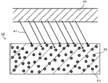
図1は、本発明に係る一実施の形態の耐アーク性絶縁物10の断面を模式的に示した図である。
FIG. 1 is a diagram schematically showing a cross section of an arc
本発明に係る一実施の形態の耐アーク性絶縁物10は、図1に示すように、フッ素系樹脂20に、フッ素系樹脂の焼成で変色しない耐熱性、耐薬品性を有する無機紫外線遮へい材30を含有して構成されている。
As shown in FIG. 1, an arc
フッ素系樹脂20としては、特に、ポリ四フッ化エチレン樹脂または四フッ化エチレン−パーフルオロアルキルビニルエーテル共重体を用いることが好ましい。ポリ四フッ化エチレン樹脂の融点は約327℃であり、また、四フッ化エチレン−パーフルオロアルキルビニルエーテル共重体の融点は約302〜310℃であり、これらはフッ素系樹脂の中でも高い耐熱性を有しているからである。
As the
また、ポリ四フッ化エチレン樹脂は溶融時の粘度が高いため、高温で溶融しても元の形状を維持することができるという特徴がある。このような特性を生かすことにより、本実施の形態の耐アーク性絶縁物10を、アークに対して適切な距離を確保して配置することで、アークによって加熱されたとしても、熱による変形を防止することができる。
In addition, since polytetrafluoroethylene resin has a high viscosity at the time of melting, it is characterized in that the original shape can be maintained even when melted at a high temperature. By taking advantage of such characteristics, the arc-
さらに、ポリ四フッ化エチレン樹脂および四フッ化エチレン−パーフルオロアルキルビニルエーテル共重体は、加熱分解時に、高分子を構成する単位構造分子となってガス化するため、炭化物が残らず、導電性物質の生成による絶縁性能の低下が起き難いという利点がある。さらに、分解してガス化する際に多量のエネルギを消費することによって冷却効果が発揮され、ポリ四フッ化エチレン樹脂自体および四フッ化エチレン−パーフルオロアルキルビニルエーテル共重体自体を保護する効果も得られる。 Furthermore, since polytetrafluoroethylene resin and tetrafluoroethylene-perfluoroalkyl vinyl ether copolymer are gasified into unit structure molecules constituting a polymer during thermal decomposition, no carbides remain, and conductive materials There is an advantage that a decrease in insulation performance due to the generation of is difficult to occur. Furthermore, a cooling effect is exhibited by consuming a large amount of energy when decomposing and gasifying, and the effect of protecting the polytetrafluoroethylene resin itself and the tetrafluoroethylene-perfluoroalkylvinyl ether copolymer itself is also obtained. It is done.
無機紫外線遮へい材30は、上記したように、フッ素系樹脂20の焼成で変色しない耐熱性、耐薬品性を有する。また、無機紫外線遮へい材30が、図1に示すように、アーク40から発生した光41のうち、主に内部劣化に関与する波長領域の光を吸収することにより、樹脂の内部での炭化物の形成を抑制し、内部に発生したガスによってフッ素系樹脂20が吹き飛ばされるという現象を防ぎ、絶縁性能の低下を抑えることができる。
As described above, the inorganic
すなわち、カーボンのような導電性物質を含有した場合には、含有量が少量であっても、フッ素系樹脂20の絶縁抵抗が低下して、近接されたアークが導電性物質を含有したフッ素系樹脂20の表面を流れやすくなり、耐アーク性が低下していた。これに対して、本実施の形態で用いられる無機紫外線遮へい材30を含有した場合には、フッ素系樹脂20の絶縁抵抗は低下せず、結果として耐アーク性の高い絶縁材料を得ることができる。
That is, when a conductive material such as carbon is contained, even if the content is small, the insulation resistance of the fluorine-based
また、本実施の形態で用いられる無機紫外線遮へい材30としては、フッ素系樹脂20の焼成温度である300℃前後の温度で変化、変色しない耐熱性を有し、かつ焼成前のフッ素系樹脂20から発生するフッ素系ガスに侵されない耐薬品性を有するものを使用することが好ましい。耐熱性や耐薬品性を持たない無機紫外線遮へい材を使用した場合、フッ素系樹脂の焼成時に変色が発生したり、炭化物が生成するなど、導電性物質を含有した場合と同様に、絶縁性能の低下を招くからである。
In addition, as the inorganic
上述したように、アーク40からの光41による劣化を抑えつつ、絶縁物の損耗を低減するためには、後述するように無機紫外線遮へい材30の含有率を適正化するとともに、適切な波長の光を吸収する無機紫外線遮へい材30を選択することが有効である。つまり、内部炭化に関与する波長領域の光を主に吸収し、それ以外の光を吸収しないようにすれば、内部炭化による絶縁性能の低下の抑制と、光と熱によるフッ素系樹脂20の損耗の低減という両方の効果が得られる耐アーク性に優れた絶縁物を得ることができると考えられる。
As described above, in order to reduce the wear of the insulator while suppressing the deterioration due to the
このような見地から本発明者等が鋭意検討を重ねた結果、白色系の無機紫外線遮へい材30をそれぞれ単独あるいは組み合わせて使用することにより、内部炭化による絶縁性能の低下の抑制と、光と熱によるフッ素系樹脂20の損耗の低減の両方の効果が得られることを見出したものである。
From these viewpoints, the present inventors have conducted intensive studies, and as a result, by using the white inorganic
次に無機紫外線遮へい材30の具体的な構成について説明する。
Next, a specific configuration of the inorganic
無機紫外線遮へい材30は、酸化チタン、酸化亜鉛(ZnO)、酸化セリウム(CeO2)のうちのいずれかで構成される。また、これらのうちのいずれかで構成された無機紫外線遮へい材30をそれぞれ単独で使用してもよいし、あるいは組み合わせて使用してもよい。例えば、酸化チタンで構成された無機紫外線遮へい材30と、酸化亜鉛で構成された無機紫外線遮へい材30とを所定の割合で混合して使用してもよい。
The inorganic
これらの無機紫外線遮へい材30は、耐熱性、耐薬品性に優れた無機物であり、フッ素系樹脂20に含有されても、焼成時の加熱で変化や変色を生じないものである。なお、酸化チタンには、その結晶状態の違いにより、ルチル型、アナターゼ型、ブルッカイト型があるが、フッ素系樹脂20に与えるダメージを抑えるため、活性度が低く、光触媒作用の小さなルチル型を選択することが好ましい。
These inorganic
無機紫外線遮へい材30を含有したときに下地を覆い隠す能力として「隠蔽力」という評価パラメータがある。この「隠蔽力」は、無機紫外線遮へい材30の表面で反射される光と無機紫外線遮へい材30に吸収される光で決まるものであり、反射光と吸収光の量が多いほど隠蔽力は高くなる。また、隠蔽力は、無機紫外線遮へい材30の粒子径とも関係があり、粒子径が小さくなる、例えば、粒子径が光の波長の1/2以下になると、一般的な反射、屈折と異なる光の散乱や回折現象が起きるため、隠蔽力が著しく低下することが知られている(例えば、色材工学ハンドブック (社)色材協会編 朝倉書店)。本発明では、紫外光を吸収し、可視領域の光をできる限り吸収しない構成を目指している。可視領域の最短波長の400nmを吸収し難くするためには、無機紫外線遮へい材30の平均粒径を200nm(0.2μm)以下にする必要がある。そのため、無機紫外線遮へい材30は、平均粒径が0.2μm以下であることが好ましい。なお、ここでの平均粒径は、空気透過法によって求められた値である。
There is an evaluation parameter called “hiding power” as the ability to cover the base when the inorganic
また、無機紫外線遮へい材30は、フッ素系樹脂の焼成で変色しない耐熱性、耐薬品性を有する白色系無機物で被覆されてもよい。無機紫外線遮へい材30が酸化チタンで構成される場合には、被覆する白色系無機物として、二酸化ケイ素(SiO2)、酸化アルミニウム(Al2O3)、窒化ホウ素(BN)などが挙げられる。また、無機紫外線遮へい材30が酸化亜鉛または酸化セリウムで構成される場合には、被覆する白色系無機物として、二酸化ケイ素(SiO2)、酸化アルミニウム(Al2O3)、窒化ホウ素(BN)、酸化チタンなどが挙げられる。無機紫外線遮へい材30を被覆する被覆層は、無機紫外線遮へい材30の表面に複数の白色系無機物からなる微粒子が付着して形成される。そのため、被覆層を形成する白色系無機物の粒径は、無機紫外線遮へい材30よりも小さく、平均粒径で、例えば20nm以下のものが好ましい。この平均粒径の範囲の白色系無機物を使用することで、無機紫外線遮へい材30の表面を密に被覆することができる。また、被覆層は、白色度を高めたり、耐薬品性を向上させたり、無機紫外線遮へい材30どうしが凝集するのを防止するなどの機能があり、上記した平均粒径の範囲の白色系無機物を使用することで、これらの機能を十分に発揮することができる。
In addition, the inorganic
なお、この被覆層を備える場合においても、無機紫外線遮へい材30(被覆層を含む)の平均粒径は、上記した理由から、平均粒径が0.2μm以下であることが好ましい。 Even in the case where this coating layer is provided, the average particle size of the inorganic ultraviolet shielding material 30 (including the coating layer) is preferably 0.2 μm or less for the reason described above.
ここで、無機紫外線遮へい材30の表面に被覆層を形成する方法について説明する。
Here, a method for forming a coating layer on the surface of the inorganic
被覆層は、例えば、複合粒子製造装置を用いて形成することができる。この複合粒子製造装置は、乾式で微粉体どうしの接合を可能にするものである。具体的には、まず、母粒子である無機紫外線遮へい材30に、子粒子である白色系無機物からなる微粒子を所定の割合で混合する。続いて、この混合された粒子を被覆層形成工程を行う容器に投入する。この被覆層形成工程を行う容器では、粒子を気相中に分散させながら、衝撃力を主体とする機械的熱的エネルギを粒子に与え、母粒子の表面に子粒子を固定化する。そして、固定化された処理粉体は、捕集器で捕集される。このようにして、無機紫外線遮へい材30の表面に、白色系無機物の微粒子からなる被覆層が形成される。
A coating layer can be formed using a composite particle manufacturing apparatus, for example. This composite particle manufacturing apparatus is a dry type and enables joining of fine powders. Specifically, first, fine particles made of a white inorganic substance, which is a child particle, are mixed in a predetermined ratio with the inorganic
上記した複合粒子製造装置として、例えば、ハイブリダイゼーションシステム(奈良機械製作所製)、循環型メカノフュージョンシステム(ホソカワミクロン社製)などが挙げられる。 Examples of the composite particle production apparatus described above include a hybridization system (manufactured by Nara Machinery Co., Ltd.), a circulation mechanofusion system (manufactured by Hosokawa Micron Corporation), and the like.
次に、フッ素系樹脂20に含まれる無機紫外線遮へい材30の含有率について説明する。
Next, the content rate of the inorganic
本実施の形態の耐アーク性絶縁物10において、内部炭化を抑制する効果を得るためには、十分な光の吸収が必要であり、それに相当する無機紫外線遮へい材30の含有率が存在する。一方、無機紫外線遮へい材30を多量に充填すると、フッ素系樹脂20中のアーク40に起因する熱の伝導が高まり、その結果、フッ素系樹脂20からなる絶縁物の損耗量が増加する。したがって、添加する無機紫外線遮へい材30の量は、十分な光の吸収が得られるならば、できる限り少量に設定することが好ましい。
In the arc
ここで、図2は、無機紫外線遮へい材30を含有したフッ素系樹脂20における、波長300nmでの光の反射率と無機紫外線遮へい材30の含有率の典型的な関係を示した図である。
Here, FIG. 2 is a diagram showing a typical relationship between the reflectance of light at a wavelength of 300 nm and the content of the inorganic
図2に示すように、無機紫外線遮へい材30の含有率が、0.1重量%以上で、大半の光が吸収される反射率が40%以下となる。一方、無機紫外線遮へい材30の含有率が、1重量%を超えると反射率の急激な減少はなく、単調に減少する。上記したように、不必要に無機紫外線遮へい材30を含有することは、フッ素系樹脂20中のアーク40に起因する熱の伝導を高め、フッ素系樹脂20からなる絶縁物の損耗量を増加させることなる。したがって、フッ素系樹脂20に含まれる無機紫外線遮へい材30の含有率は、0.1重量%以上1重量%以下が好ましい範囲となる。また、この範囲において、安定した配合物の得やすさや、充填率誤差の影響の少なさ、製造のしやすさという観点から、フッ素系樹脂20に含まれる無機紫外線遮へい材30の含有率は、0.2重量%以上0.6重量%以下とすることが好ましい。
As shown in FIG. 2, the content of the inorganic
次に、耐アーク性絶縁物10の製造方法について説明する。
Next, a method for manufacturing the arc
前述したフッ素系樹脂20の粉末に、前述した方法で形成された、白色系無機物で被覆された無機紫外線遮へい材30を、フッ素系樹脂20の重量の0.1〜1%添加し、均一に混合する。均一に混合された混合物を所定の型に充填して圧縮形成し、圧縮形成体を作製する。ここで、遮断器のノズルを作製する場合には、遮断器のノズルを作製できるサイズの、例えば、円柱状の圧縮形成体を作製する。
To the powder of the
続いて、圧縮形成体を炉に設置し、温度を370℃程度まで徐々に上昇させ、フッ素系樹脂20の粉末を溶融して焼成する。その後、自然冷却により室温まで冷却し、成形品である耐アーク性絶縁物10が得られる。上記した全製造工程には40〜50時間程度費やされる。
Subsequently, the compression formed body is placed in a furnace, the temperature is gradually increased to about 370 ° C., and the powder of the
ここで、遮断器のノズルを作製する場合には、円柱状の成形品をノズルの形状に機械加工することで、遮断器のノズルが得られる。 Here, when producing the nozzle of a circuit breaker, the nozzle of a circuit breaker is obtained by machining a cylindrical molded product into the shape of the nozzle.
上記したように、本発明に係る一実施の形態の耐アーク性絶縁物10によれば、フッ素系樹脂20に、無機紫外線遮へい材30を所定の割合で含有することで、無機紫外線遮へい材30が、内部劣化に関与する紫外領域の光を吸収することができる。これによって、樹脂の内部での炭化物の形成を抑制し、内部に発生したガスによってフッ素系樹脂20が吹き飛ばされるという現象を防ぐことができ、絶縁性能の低下を抑えることができる。また、無機紫外線遮へい材30の表面を被覆層で覆うことで、白色度を高めたり、耐薬品性を向上させたり、無機紫外線遮へい材30どうしが凝集するのを防止することができる。
As described above, according to the arc-
また、無機紫外線遮へい材30は、内部劣化の原因となる波長領域以外の光をほとんど吸収しないため、光や熱を吸収することによって生じる絶縁物表面からの樹脂の分解、気化、散逸を抑制することができる。そのため、内部劣化を抑えつつ、全体としての絶縁物の減少(損耗)を抑制することができる。
Moreover, since the inorganic
さらに、耐アーク性絶縁物10における無機紫外線遮へい材30の含有量は微量であるため、フッ素系樹脂の熱伝導率が上昇することがない。そのため、熱伝導領域が拡大することで生じるフッ素系樹脂の損耗量の増加を抑えることができる。また、耐アーク性絶縁物10における無機紫外線遮へい材30の含有量は微量であるため、フッ素系樹脂20とほぼ同程度の機械的強度を維持することができる。
Furthermore, since the content of the inorganic
次に、本発明に係る耐アーク性絶縁物10が、アークによる内部劣化を防止する効果が優れていることについて説明する。
Next, it will be described that the arc-
(耐アーク性、機械的強度および体積抵抗率の評価)
耐アーク性、機械的強度および体積抵抗率の評価を行うため、試料1〜試料7を以下に示すように作製した。
(Evaluation of arc resistance, mechanical strength and volume resistivity)
In order to evaluate arc resistance, mechanical strength, and volume resistivity, Samples 1 to 7 were prepared as shown below.
(試料1)
平均粒径が25μmのポリ四フッ化エチレン樹脂の粉末に、平均粒径が0.01μmのルチル型の酸化チタンをこの樹脂の重量の0.6%添加し、均一に混合した。なお、ここでの平均粒径は、空気透過法によって求められた値である。
(Sample 1)
To a polytetrafluoroethylene resin powder having an average particle diameter of 25 μm, 0.6% of the weight of the resin was added to a rutile type titanium oxide having an average particle diameter of 0.01 μm and mixed uniformly. Here, the average particle diameter is a value obtained by an air permeation method.
続いて、均一に混合された混合物を、内径が100mm、内壁の高さが100mmの型に充填して、温度25℃(室温)、圧力50MPaで圧縮形成し、圧縮形成体を作製した。 Subsequently, the uniformly mixed mixture was filled in a mold having an inner diameter of 100 mm and an inner wall height of 100 mm, and compression-molded at a temperature of 25 ° C. (room temperature) and a pressure of 50 MPa to produce a compression-molded body.
続いて、圧縮形成体を炉に設置し、温度を370℃程度まで徐々に上昇させ、フッ素系樹脂20の粉末を溶融して焼成した。その後、自然冷却により室温まで冷却し、機械加工により、直径が100mm、厚さが3mm(耐アーク性試験用および体積抵抗率の測定用)と、直径が100mm、厚さが1mm(引張り強度試験用)の円柱状の試料1を得た。
Subsequently, the compression molded body was placed in a furnace, the temperature was gradually increased to about 370 ° C., and the powder of the
(試料2)
平均粒径が25μmのポリ四フッ化エチレン樹脂の粉末に、平均粒径が0.02μmの酸化亜鉛をこの樹脂の重量の0.6%添加し、均一に混合した。
(Sample 2)
To a powder of polytetrafluoroethylene resin having an average particle size of 25 μm, 0.6% of the weight of the resin was added to zinc oxide having an average particle size of 0.02 μm and mixed uniformly.
以後の作製工程は、上記した試料1の場合と同じとし、試料1と同サイズの試料2を得た。
The subsequent manufacturing steps were the same as those of the sample 1 described above, and a
(試料3)
平均粒径が25μmのポリ四フッ化エチレン樹脂の粉末に、平均粒径が0.01μmの酸化セリウムをこの樹脂の重量の0.6%添加し、均一に混合した。
(Sample 3)
To a polytetrafluoroethylene resin powder having an average particle diameter of 25 μm, cerium oxide having an average particle diameter of 0.01 μm was added by 0.6% of the weight of the resin and mixed uniformly.
以後の作製工程は、上記した試料1の場合と同じとし、試料1と同サイズの試料3を得た。
The subsequent manufacturing steps were the same as in the case of Sample 1 described above, and
(試料4)
平均粒径が25μmのポリ四フッ化エチレン樹脂の粉末に、平均粒径が0.02μmの酸化アルミニウムで被覆された、平均粒径が0.02μmの酸化亜鉛をこの樹脂の重量の0.6%添加し、均一に混合した。
(Sample 4)
A powder of polytetrafluoroethylene resin having an average particle size of 25 μm was coated with zinc oxide having an average particle size of 0.02 μm coated with aluminum oxide having an average particle size of 0.02 μm. % Was added and mixed uniformly.
以後の作製工程は、上記した試料1の場合と同じとし、試料1と同サイズの試料4を得た。 The subsequent manufacturing steps were the same as in the case of Sample 1 described above, and Sample 4 having the same size as Sample 1 was obtained.
(試料5)
平均粒径が25μmのポリ四フッ化エチレン樹脂の粉末に、平均粒径が0.2μmの炭素をこの樹脂の重量の0.4%添加し、均一に混合した。
(Sample 5)
Carbon having an average particle diameter of 0.2 μm was added to a polytetrafluoroethylene resin powder having an average particle diameter of 25 μm in an amount of 0.4% of the weight of the resin, and mixed uniformly.
以後の作製工程は、上記した試料1の場合と同じとし、試料1と同サイズの試料5を得た。 The subsequent manufacturing steps were the same as in the case of Sample 1 described above, and Sample 5 having the same size as Sample 1 was obtained.
(試料6)
平均粒径が25μmのポリ四フッ化エチレン樹脂の粉末を、内径が100mm、内壁の高さが100mmの型に充填して、温度25℃(室温)、圧力50kPaで圧縮形成し、圧縮形成体を作製した。
(Sample 6)
A polytetrafluoroethylene resin powder having an average particle size of 25 μm is filled into a mold having an inner diameter of 100 mm and an inner wall height of 100 mm, and compression-formed at a temperature of 25 ° C. (room temperature) and a pressure of 50 kPa. Was made.
以後の作製工程は、上記した試料1の場合と同じとし、試料1と同サイズの試料6を得た。 The subsequent manufacturing steps were the same as those of the sample 1 described above, and a sample 6 having the same size as the sample 1 was obtained.
(試料7)
平均粒径が25μmのポリ四フッ化エチレン樹脂の粉末に、平均粒径が10μmの窒化ホウ素をこの樹脂の重量の10%添加し、均一に混合した。
(Sample 7)
To a polytetrafluoroethylene resin powder having an average particle diameter of 25 μm, boron nitride having an average particle diameter of 10 μm was added at 10% of the weight of the resin and mixed uniformly.
以後の作製工程は、上記した試料1の場合と同じとし、試料1と同サイズの試料7を得た。 The subsequent manufacturing steps were the same as in the case of Sample 1 described above, and Sample 7 having the same size as Sample 1 was obtained.
上記した方法で作製された試料1〜試料7を用いて、耐アーク性試験、体積抵抗率の測定、引張り強度試験を行った。ここで、耐アーク性試験は、日本工業規格JIS K6911に準じて行った。なお、耐アーク性とは、絶縁材料がアークによる劣化に耐える能力であり、導通や発火に至るまでの時間を測定した秒数である。体積抵抗率の測定は、JIS K6911に準じて行った。引張り強度試験は、JIS K6891に準じて行った。表1に、試料1〜試料7における上記した試験結果を示す。なお、試料1〜試料4は、本発明に係る耐アーク性絶縁物であり、試料5〜試料7は、比較例である。 An arc resistance test, a volume resistivity measurement, and a tensile strength test were performed using the samples 1 to 7 manufactured by the above-described method. Here, the arc resistance test was performed in accordance with Japanese Industrial Standard JIS K6911. Arc resistance refers to the ability of an insulating material to withstand deterioration due to arc, and is the number of seconds measured for the time until conduction and ignition. The volume resistivity was measured according to JIS K6911. The tensile strength test was performed according to JIS K6891. Table 1 shows the test results described above for Sample 1 to Sample 7. Samples 1 to 4 are arc-resistant insulators according to the present invention, and Samples 5 to 7 are comparative examples.
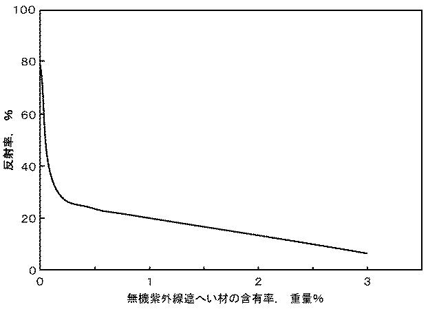
表1に示すように、試料5のように、導電性物質である炭素を含有した場合には、体積抵抗率や耐アーク性が大幅に低下することがわかった。これに対し、試料1〜試料4のように、無機紫外線遮へい材を所定量含有した場合には、体積抵抗率が高く、耐アーク性は、従来の絶縁物として広く使用されている試料6における耐アーク性と同じレベルを維持できることがわかった。 As shown in Table 1, it was found that the volume resistivity and arc resistance are significantly lowered when carbon as a conductive material is contained as in Sample 5. On the other hand, when a predetermined amount of the inorganic ultraviolet shielding material is contained as in Sample 1 to Sample 4, the volume resistivity is high and the arc resistance is the same as that in Sample 6 widely used as a conventional insulator. It was found that the same level of arc resistance can be maintained.
また、添加物の含有量が多い試料7は、引張り強度が小さくなることがわかった。また、試料1〜試料4における引張り強度は、従来の絶縁物として広く使用されている試料6よりも若干低下するものの、試料6における引張り強度と大きな差はなく、同程度であった。 Moreover, it turned out that the sample 7 with much content of an additive becomes small in tensile strength. Moreover, although the tensile strength in the samples 1 to 4 is slightly lower than that of the sample 6 that is widely used as a conventional insulator, the tensile strength in the sample 6 is not significantly different and is about the same.
(内部劣化の有無および重量損耗量の評価)
内部劣化の有無および重量損耗量の評価を行うため、試料8〜試料10を以下に示すように作製した。
(Evaluation of internal deterioration and weight loss)
In order to evaluate the presence / absence of internal deterioration and the amount of weight loss, Samples 8 to 10 were prepared as shown below.
(試料8)
平均粒径が25μmのポリ四フッ化エチレン樹脂の粉末に、平均粒径が0.01μmのルチル型の酸化チタンをこの樹脂の重量の0.5%添加し、均一に混合した。
(Sample 8)
To a polytetrafluoroethylene resin powder having an average particle diameter of 25 μm, 0.5% of the weight of the resin was added to a rutile type titanium oxide having an average particle diameter of 0.01 μm and mixed uniformly.
以後の作製工程は、上記した試料1の場合と同じとし、型を代えて、直径が200mm、高さが250mmの試料8を得た。 The subsequent manufacturing steps were the same as those of the sample 1 described above, and the sample 8 having a diameter of 200 mm and a height of 250 mm was obtained by changing the mold.
(試料9)
平均粒径が25μmのポリ四フッ化エチレン樹脂の粉末に、平均粒径が0.02μmの酸化亜鉛をこの樹脂の重量の0.5%添加し、均一に混合した。
(Sample 9)
Zinc oxide having an average particle size of 0.02 μm was added to a polytetrafluoroethylene resin powder having an average particle size of 25 μm in an amount of 0.5% of the weight of the resin and mixed uniformly.
以後の作製工程は、上記した試料1の場合と同じとし、型を代えて、直径が200mm、高さが250mmの試料9を得た。 Subsequent manufacturing steps were the same as in the case of Sample 1 described above, and the sample was changed to obtain Sample 9 having a diameter of 200 mm and a height of 250 mm.
(試料10)
平均粒径が25μmのポリ四フッ化エチレン樹脂の粉末に、平均粒径が0.01μmの酸化セリウムをこの樹脂の重量の0.5%添加し、均一に混合した。
(Sample 10)
To a polytetrafluoroethylene resin powder having an average particle diameter of 25 μm, 0.5% of the weight of the resin was added with cerium oxide having an average particle diameter of 0.01 μm and mixed uniformly.
以後の作製工程は、上記した試料1の場合と同じとし、型を代えて、直径が200mm、高さが250mmの試料10を得た。
Subsequent manufacturing steps were the same as in the case of Sample 1 described above, and the
なお、試料8〜試料10は、本発明に係る耐アーク性絶縁物であり、比較のため上記した試料6〜試料7に対しても、型を代えて、直径が200mm、高さが250mmの試料を作製し、内部劣化の有無および重量損耗量の評価を行った。 Samples 8 to 10 are arc-resistant insulators according to the present invention. For comparison, the samples 6 to 7 have a diameter of 200 mm and a height of 250 mm instead of the mold. Samples were prepared and evaluated for internal deterioration and weight wear.
内部劣化の有無は、各試料を機械加工して、同形状のガス遮断器用ノズルを作製し、これらノズルを遮断器に取付け、同様の条件で遮断試験を実施した後のノズル断面を観察し、劣化の有無を観察した。具体的には、試料の断面を観察し、内部炭化跡の有無を調べた。 Presence or absence of internal deterioration, machine each sample, make nozzles for the same shape of the gas circuit breaker, attach these nozzles to the circuit breaker, observe the cross section of the nozzle after performing the interruption test under the same conditions, The presence or absence of deterioration was observed. Specifically, the cross section of the sample was observed to check for the presence of internal carbonization traces.
重量損耗量は、内部劣化試験で使用したノズルの試験前と試験後の試料の重量を測定し、それぞれの差を求めることで評価を行った。なお、この評価においては、より正確に比較するため、試験前後の重量差を遮断試験で注入したエネルギ量で除して求めた、単位エネルギ当りの重量変化を用いた。 The weight wear amount was evaluated by measuring the weight of the nozzle used in the internal deterioration test before and after the test, and determining the difference between the weights. In this evaluation, in order to compare more accurately, the weight change per unit energy obtained by dividing the weight difference before and after the test by the amount of energy injected in the interruption test was used.
表2に、試料6〜試料10における上記した試験結果を示す。表2には、内部劣化がある場合を「有」、内部劣化がない場合を「無」と示している。ここで、内部劣化がない場合とは、内部炭化跡がなく、内部炭化に伴うエロージョンもない場合である。また、重量損耗量は、試料6における単位エネルギ当たりの重量損耗量を100としたときの相対値で示されている。例えば、試料6における単位エネルギ当たりの重量損耗量を超える場合には、相対値は100を超え、試料6における単位エネルギ当たりの重量損耗量を下回る場合には、相対値は100を下回る。
Table 2 shows the test results described above for Sample 6 to
表2に示すように、試料8〜試料10においては、内部炭化跡がなく、内部炭化に伴うエロージョンもなく、内部劣化は確認されなかった。また、試料8〜試料10における重量損耗量は、従来の絶縁物として広く使用されている試料6における重量損耗量と大きな差はなく、同程度であった。一方、無機紫外線遮へい材を有さない試料6においては、内部劣化が多数観察された。また、添加物の含有量が多い試料7は、重量損耗量が大きかった。 As shown in Table 2, Sample 8 to Sample 10 had no internal carbonization trace, no erosion due to internal carbonization, and no internal deterioration was confirmed. Moreover, the weight wear amount in the samples 8 to 10 was not different from the weight wear amount in the sample 6 widely used as a conventional insulator, and was similar. On the other hand, in the sample 6 having no inorganic ultraviolet shielding material, many internal deteriorations were observed. In addition, Sample 7 having a large content of additives had a large weight wear amount.
上記結果から、本発明に係る耐アーク性絶縁物である試料8〜試料10は、フッ素系樹脂に適切な紫外線遮へい剤を適量含有することで、アーク光が原因となる内部炭化を抑制しつつ、アークからの余分な光や熱を吸収しないことにより、絶縁物の重量損耗量が抑制されると考えられる。 From the above results, Samples 8 to 10 which are arc-resistant insulators according to the present invention contain an appropriate amount of an ultraviolet shielding agent suitable for a fluorine-based resin, thereby suppressing internal carbonization caused by arc light. It is considered that weight loss of the insulator is suppressed by not absorbing excess light and heat from the arc.
10…耐アーク性絶縁物、20…フッ素系樹脂、30…無機紫外線遮へい材、40…アーク、41…光。
DESCRIPTION OF
Claims (8)
所定のフッ素系樹脂に、前記フッ素系樹脂の焼成で変色しない耐熱性を有する白色系無機物で被覆された、前記フッ素系樹脂の焼成で変色しない耐熱性を有する無機紫外線遮へい材を前記フッ素系樹脂の重量の0.1〜1%含有してなることを特徴とする耐アーク性絶縁物。 An arc-resistant insulator disposed in the vicinity of an arc generated between the electrodes,
A predetermined fluorine-based resin coated with a white inorganic material having heat resistance not discolored by baking of the fluorine-based resin, and an inorganic ultraviolet shielding material having heat resistance not discolored by baking of the fluorine-based resin, the fluorine-based resin An arc-resistant insulating material comprising 0.1 to 1% of the weight of
前記絶縁物が、請求項1乃至7のいずれか1項記載の耐アーク性絶縁物であることを特徴とする遮断器。 A fixed electrode, a movable electrode that contacts and separates from the fixed electrode, and a nozzle made of an insulating material provided between the electrodes, and is extinguished by blowing gas from the nozzle to an arc generated between the electrodes when current is interrupted A circuit breaker that
The circuit breaker according to any one of claims 1 to 7, wherein the insulator is an arc-resistant insulator.
Priority Applications (1)
| Application Number | Priority Date | Filing Date | Title |
|---|---|---|---|
| JP2008207604A JP5269516B2 (en) | 2008-08-12 | 2008-08-12 | Arc resistant insulation and circuit breakers |
Applications Claiming Priority (1)
| Application Number | Priority Date | Filing Date | Title |
|---|---|---|---|
| JP2008207604A JP5269516B2 (en) | 2008-08-12 | 2008-08-12 | Arc resistant insulation and circuit breakers |
Publications (2)
| Publication Number | Publication Date |
|---|---|
| JP2010044930A true JP2010044930A (en) | 2010-02-25 |
| JP5269516B2 JP5269516B2 (en) | 2013-08-21 |
Family
ID=42016166
Family Applications (1)
| Application Number | Title | Priority Date | Filing Date |
|---|---|---|---|
| JP2008207604A Active JP5269516B2 (en) | 2008-08-12 | 2008-08-12 | Arc resistant insulation and circuit breakers |
Country Status (1)
| Country | Link |
|---|---|
| JP (1) | JP5269516B2 (en) |
Cited By (2)
| Publication number | Priority date | Publication date | Assignee | Title |
|---|---|---|---|---|
| JP2012190715A (en) * | 2011-03-11 | 2012-10-04 | Toshiba Corp | Arc-resistant insulator and breaker |
| JP2014203557A (en) * | 2013-04-02 | 2014-10-27 | 株式会社東芝 | Arc resistant insulator, method of producing arc resistant insulator, and gas blast circuit breaker |
Citations (3)
| Publication number | Priority date | Publication date | Assignee | Title |
|---|---|---|---|---|
| JPS57119427A (en) * | 1981-01-19 | 1982-07-24 | Hitachi Ltd | Breaker |
| JPS57210507A (en) * | 1981-06-22 | 1982-12-24 | Hitachi Ltd | Breaker |
| JP2003162080A (en) * | 2001-09-17 | 2003-06-06 | Ricoh Co Ltd | Coating liquid for electrophotographic photosensitive body, electrophotographic photosensitive body, electrophotographic method and electrophotographic device |
-
2008
- 2008-08-12 JP JP2008207604A patent/JP5269516B2/en active Active
Patent Citations (3)
| Publication number | Priority date | Publication date | Assignee | Title |
|---|---|---|---|---|
| JPS57119427A (en) * | 1981-01-19 | 1982-07-24 | Hitachi Ltd | Breaker |
| JPS57210507A (en) * | 1981-06-22 | 1982-12-24 | Hitachi Ltd | Breaker |
| JP2003162080A (en) * | 2001-09-17 | 2003-06-06 | Ricoh Co Ltd | Coating liquid for electrophotographic photosensitive body, electrophotographic photosensitive body, electrophotographic method and electrophotographic device |
Cited By (2)
| Publication number | Priority date | Publication date | Assignee | Title |
|---|---|---|---|---|
| JP2012190715A (en) * | 2011-03-11 | 2012-10-04 | Toshiba Corp | Arc-resistant insulator and breaker |
| JP2014203557A (en) * | 2013-04-02 | 2014-10-27 | 株式会社東芝 | Arc resistant insulator, method of producing arc resistant insulator, and gas blast circuit breaker |
Also Published As
| Publication number | Publication date |
|---|---|
| JP5269516B2 (en) | 2013-08-21 |
Similar Documents
| Publication | Publication Date | Title |
|---|---|---|
| Dittrich et al. | The influence of layered, spherical, and tubular carbon nanomaterials' concentration on the flame retardancy of polypropylene | |
| Maity et al. | Degradation of polymer dielectrics with nanometric metal-oxide fillers due to surface discharges | |
| US9475906B2 (en) | Arc-extinguishing insulation material molded product and gas circuit breaker including the same | |
| JP2012023007A (en) | Direct-current power cable with space charge reducing effect | |
| CN107710339B (en) | Partial discharge resistant electrically insulating resin composition | |
| WO2007060201A1 (en) | Perfluoropolymer composition | |
| Kavitha et al. | Impact of permittivity and concentration of filler nanoparticles on dielectricproperties<? oxy_delete author=" tdodds" timestamp=" 20161221T094426+ 0000" content=" we"?> of polymer nanocomposites | |
| JP5679873B2 (en) | Arc resistant insulation and circuit breakers | |
| JP5269516B2 (en) | Arc resistant insulation and circuit breakers | |
| JP4945104B2 (en) | Insulator with excellent arc resistance | |
| Du et al. | Thermal conductivity and arcing resistance of micro or hybrid BN filled polyethylene under pulse strength | |
| Rybiński et al. | Influence of cenosphere particles on thermal properties composites of silicon rubber | |
| Tang et al. | Filler and additive effects on partial discharge degradation of PET films used in PV devices | |
| JP4931721B2 (en) | Insulation nozzle for circuit breaker | |
| JP6157896B2 (en) | Arc-resistant insulator, method for manufacturing arc-resistant insulator, and gas circuit breaker | |
| Qenawy et al. | Evaluation of dielectric strength of SiR/TiO2 composites using feed‐forward neural network | |
| CN103854917B (en) | It is used for the fluoroplastics matrix composite material of arc extinguishing used in electronic installation | |
| CN106633356B (en) | A kind of ethylene and tetra fluoloethylene copolymer resin heat-shrinkage material and preparation method thereof | |
| JP2013214451A (en) | Arc-resistant insulator and circuit breaker | |
| Wang et al. | Influence of ZnO nanoparticles on the light absorption spectrum of PMMA for ablation dominated arc interruption | |
| JP2581606B2 (en) | SF lower 6 gas breaker | |
| Gao et al. | Effects of nanofiller and voltage stabilizer on partial discharge resistance of polypropylene/elastomer blends: A comparison study | |
| WO2020044552A1 (en) | Arc resistant insulating molded body, nozzle for gas circuit breaker, and gas circuit breaker | |
| JPH0145690B2 (en) | ||
| Peng et al. | Percolation and catalysis effect of bamboo‐based active carbon on the thermal and flame retardancy properties of ethylene vinyl‐acetate rubber |
Legal Events
| Date | Code | Title | Description |
|---|---|---|---|
| A621 | Written request for application examination |
Free format text: JAPANESE INTERMEDIATE CODE: A621 Effective date: 20110223 |
|
| RD02 | Notification of acceptance of power of attorney |
Free format text: JAPANESE INTERMEDIATE CODE: A7422 Effective date: 20120614 |
|
| A977 | Report on retrieval |
Free format text: JAPANESE INTERMEDIATE CODE: A971007 Effective date: 20120803 |
|
| A131 | Notification of reasons for refusal |
Free format text: JAPANESE INTERMEDIATE CODE: A131 Effective date: 20120925 |
|
| A521 | Written amendment |
Free format text: JAPANESE INTERMEDIATE CODE: A523 Effective date: 20121121 |
|
| A131 | Notification of reasons for refusal |
Free format text: JAPANESE INTERMEDIATE CODE: A131 Effective date: 20130226 |
|
| A521 | Written amendment |
Free format text: JAPANESE INTERMEDIATE CODE: A523 Effective date: 20130327 |
|
| TRDD | Decision of grant or rejection written | ||
| A01 | Written decision to grant a patent or to grant a registration (utility model) |
Free format text: JAPANESE INTERMEDIATE CODE: A01 Effective date: 20130416 |
|
| A61 | First payment of annual fees (during grant procedure) |
Free format text: JAPANESE INTERMEDIATE CODE: A61 Effective date: 20130508 |
|
| R151 | Written notification of patent or utility model registration |
Ref document number: 5269516 Country of ref document: JP Free format text: JAPANESE INTERMEDIATE CODE: R151 |