JP2010042873A - Sheet feeding apparatus and image forming apparatus - Google Patents
Sheet feeding apparatus and image forming apparatus Download PDFInfo
- Publication number
- JP2010042873A JP2010042873A JP2008206041A JP2008206041A JP2010042873A JP 2010042873 A JP2010042873 A JP 2010042873A JP 2008206041 A JP2008206041 A JP 2008206041A JP 2008206041 A JP2008206041 A JP 2008206041A JP 2010042873 A JP2010042873 A JP 2010042873A
- Authority
- JP
- Japan
- Prior art keywords
- sheet
- roller
- feeding
- unit
- separation
- Prior art date
- Legal status (The legal status is an assumption and is not a legal conclusion. Google has not performed a legal analysis and makes no representation as to the accuracy of the status listed.)
- Granted
Links
Images


Classifications
-
- B—PERFORMING OPERATIONS; TRANSPORTING
- B65—CONVEYING; PACKING; STORING; HANDLING THIN OR FILAMENTARY MATERIAL
- B65H—HANDLING THIN OR FILAMENTARY MATERIAL, e.g. SHEETS, WEBS, CABLES
- B65H3/00—Separating articles from piles
- B65H3/46—Supplementary devices or measures to assist separation or prevent double feed
- B65H3/52—Friction retainers acting on under or rear side of article being separated
- B65H3/5246—Driven retainers, i.e. the motion thereof being provided by a dedicated drive
- B65H3/5253—Driven retainers, i.e. the motion thereof being provided by a dedicated drive the retainers positioned under articles separated from the top of the pile
- B65H3/5261—Retainers of the roller type, e.g. rollers
-
- B—PERFORMING OPERATIONS; TRANSPORTING
- B65—CONVEYING; PACKING; STORING; HANDLING THIN OR FILAMENTARY MATERIAL
- B65H—HANDLING THIN OR FILAMENTARY MATERIAL, e.g. SHEETS, WEBS, CABLES
- B65H2511/00—Dimensions; Position; Numbers; Identification; Occurrences
- B65H2511/50—Occurence
- B65H2511/51—Presence
-
- B—PERFORMING OPERATIONS; TRANSPORTING
- B65—CONVEYING; PACKING; STORING; HANDLING THIN OR FILAMENTARY MATERIAL
- B65H—HANDLING THIN OR FILAMENTARY MATERIAL, e.g. SHEETS, WEBS, CABLES
- B65H2513/00—Dynamic entities; Timing aspects
- B65H2513/50—Timing
- B65H2513/512—Starting; Stopping
-
- B—PERFORMING OPERATIONS; TRANSPORTING
- B65—CONVEYING; PACKING; STORING; HANDLING THIN OR FILAMENTARY MATERIAL
- B65H—HANDLING THIN OR FILAMENTARY MATERIAL, e.g. SHEETS, WEBS, CABLES
- B65H2801/00—Application field
- B65H2801/03—Image reproduction devices
- B65H2801/06—Office-type machines, e.g. photocopiers
Landscapes
- Engineering & Computer Science (AREA)
- Mechanical Engineering (AREA)
- Sheets, Magazines, And Separation Thereof (AREA)
Abstract
Description
本発明は、シート給送装置及び画像形成装置に関し、特に画像形成部にシートを1枚ずつ分離して給送するためのシート分離給送部の構成に関する。 The present invention relates to a sheet feeding apparatus and an image forming apparatus, and more particularly to a configuration of a sheet separating and feeding section for separating and feeding sheets one by one to an image forming section.
近年、プリンタ、複写機、ファクシミリ等の画像形成装置は、シートを1枚ずつ分離して画像形成部に給送するためのシート給送装置を備えており、このようなシート給送装置はシートを1枚ずつ分離して給送するためのシート分離給送部を備えている。 2. Description of the Related Art In recent years, image forming apparatuses such as printers, copiers, and facsimiles are provided with a sheet feeding device for separating sheets one by one and feeding them to an image forming unit. A sheet separating and feeding unit for separating and feeding the sheets one by one is provided.
このようなシート分離給送部としては、シート給送方向に回転する給送ローラと、給送ローラに所定の圧力で圧接する分離ローラと、分離ローラと連結されたトルクリミッタとを備えた、リタード分離方式がある(特許文献1参照)。 As such a sheet separating and feeding section, a feeding roller that rotates in the sheet feeding direction, a separation roller that is pressed against the feeding roller with a predetermined pressure, and a torque limiter that is connected to the separation roller, There is a retard separation system (see Patent Document 1).
分離ローラの給送ローラに対する押圧力やトルクリミッタのトルク値は、給送ローラと分離ローラのニップ部にシートが無い場合や、シートが1枚のみニップされている場合には、分離ローラが給送ローラやシートに従動回転するように設定されている。また、分離ローラの押圧力やトルクリミッタのトルク値は、給送ローラと分離ローラのニップ部に複数枚のシートが進入してきた場合には、分離ローラは逆回転するように設定されている。 The pressing force of the separation roller against the feeding roller and the torque limiter torque value are determined by the separation roller when there is no sheet in the nip between the feeding roller and the separation roller or when only one sheet is nipped. It is set to rotate following the feed roller and the sheet. Further, the pressing force of the separating roller and the torque value of the torque limiter are set so that the separating roller rotates in the reverse direction when a plurality of sheets enter the nip portion between the feeding roller and the separating roller.
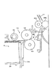
図7は、このようなリタード分離方式のシート分離給送部を備えた従来のシート給送装置の構成を示す図である。図7において、200はシートSを収納(支持)するカセット、203はカセット200のシート給送方向下流側側壁、201はカセット200に上下方向に移動可能に設けられた中板であり、この中板201にシートSが積載されている。
FIG. 7 is a diagram illustrating a configuration of a conventional sheet feeding apparatus including such a retard separation type sheet separating and feeding unit. In FIG. 7,
129は、カセット200に収納された最上位のシートSaを給送するピックアップローラである。130は例えばウレタンにより形成されたフィードローラ、131は不図示のバネによりフィードローラ130と圧接する、例えばEPDM(エチレン−プロピレン−ジエンゴム)により形成されたリタードローラである。
そして、リタードローラ131がフィードローラ130に圧接することにより、リタードローラ131とフィードローラ130との間には、リタードローラ131の、フィードローラ130と接触している表面部が圧縮された状態で分離ニップ部Nが形成される。
Then, when the
なお、ピックアップローラ129により送り出された最上位のシートSaは、フィードローラ130とリタードローラ131とにより形成される分離ニップ部Nに給送される。また、303は分離ニップ部Nから搬送ローラ対305a,305bまで間に設けられた搬送ガイド302により形成される搬送パスである。
Note that the uppermost sheet Sa sent out by the
このように構成された従来のシート給送装置において、シートの給送を行う場合は、まずピックアップローラ129が回転し、カセット200に収納された最上位のシートSaを分離ニップ部Nに搬送する。
In the conventional sheet feeding apparatus configured as described above, when feeding a sheet, first, the
そして、分離ニップ部NにシートSaが一枚だけ搬送された場合には、図8の(a)に示すようにトルクリミッタの作用によりリタードローラ131への駆動が遮断されて、リタードローラ131はシートSaに連れ回りする。これにより、シートSaは搬送パス303を通過して行く。
When only one sheet Sa is conveyed to the separation nip N, the drive to the
一方、分離ニップ部Nに複数枚のシートが搬送された場合は、トルクリミッタの作用によりリタードローラ131は、フィードローラ130と連れ回りすることなくフィードローラ130と逆方向に回転する。そして、このようにリタードローラ131がシートを搬送する方向とは逆方向に回転することにより、フィードローラ130に接している一枚のシートSaのみが下流側に搬送される。そして、図8の(b)に示すように他のシートはリタードローラ131によりシート給送方向上流側に戻され、これにより、シートの重送を防ぐことができる。
On the other hand, when a plurality of sheets are conveyed to the separation nip portion N, the
ところで、このような従来のシート給送装置及びこれを備えた画像形成装置において、装置の使用時間が多くなるにつれてフィードローラ130及びリタードローラ131が摩耗する。そして、摩耗が進むと、シートとリタードローラとの間の摩擦力と、トルクリミッタのトルク+リタードローラの回転抵抗とが、下記の式(1)に示す関係となる場合がある。
シートとリタードローラとの間の摩擦力
<トルクリミッタのトルク+リタードローラの回転抵抗・・・(1)
By the way, in such a conventional sheet feeding apparatus and an image forming apparatus including the same, the
Frictional force between sheet and retard roller
<Torque limiter torque + retard roller rotation resistance (1)
この場合、シートが分離ニップ部Nに搬送された際、リタードローラ131は、フィードローラ130で送り出されるシートと連れ回りすることなく停止するようになる。即ち、リタードローラ131の連れ回り不良が発生する。なお、リタードローラ131が連れ回り不良となる状態となった場合でも、1枚のシートが分離ニップ部Nに搬送された際、下記の式(2)の関係が成立すればシートの分離搬送は行われる。
フィードローラとシートの間の摩擦力
>シートとリタードローラとの間の摩擦力・・・(2)
In this case, when the sheet is conveyed to the separation nip portion N, the
Frictional force between feed roller and sheet
> Friction force between the sheet and the retard roller (2)
また、2枚以上のシートが分離ニップ部Nに搬送された場合でも、下記の式(3)の関係が成立すればシートの分離搬送は行われる。
シートとシートとの間の摩擦力
<シートとリタードローラとの間の摩擦力・・・(3)
Even when two or more sheets are conveyed to the separation nip portion N, the sheets are separated and conveyed as long as the following expression (3) is satisfied.
Friction force between sheets
<Friction force between the sheet and the retard roller (3)
さらに、リタードローラ131が連れ回り不良を発生する状態となった場合でも、通常は、リタードローラ131とフィードローラ130との間の摩擦力は、シートとリタードローラ131との間の摩擦力よりも大きい。このため、下記の式(4)の関係が成立し、シートが分離ニップ部Nに進入する前は、リタードローラ131が回転するため、シートは分離ニップ部Nに進入し、搬送される。
フィードローラとリタードローラとの間の摩擦力
>トルクリミッタのトルク+リタードローラの回転抵抗・・・(4)
Further, even when the
Friction force between feed roller and retard roller
> Torque limiter torque + retard roller rotation resistance (4)
しかし、リタードローラ131の摩耗は均一に発生するわけではなく、装置の使用時間が多くなるにつれて、リタードローラ131の特定の部位において摩耗が進むようになる。すなわち、式(1)の状態は、ローラの全周で生じるのではなく、一部分が他の部分よりも少し摩耗が進むと、そこで回転が停止する頻度が高くなり、停止するとシートが擦れることによりその部分での摩耗が急激に進むことになる。このようにして、リタードローラ131は部分的に摩耗してしまい、シートに連れ回りできなくなる。
However, the wear of the
そして、画像形成装置を停止した際、その摩耗が進んだ特定の部位がフィードローラ130に対向して圧接した状態でリタードローラ131が停止することになり、この場合、フィードローラ130への圧接力によって特定の部位にへこみが発生する。さらに、この状態が長時間続くと、図9に示すように、その特定の部位のへこみが大きくなり戻らなくなる。
Then, when the image forming apparatus is stopped, the
ここで、このようにへこみが大きくなると、リタードローラ131の回転抵抗が増大し、この状態でフィードローラ130が回転すると、リタードローラ表面がさらに削られてしまう。そして、このような現象が繰り返されると、リタードローラ131の特定の部位のみに摩耗と、大きなへこみが発生する。この結果、(1)の左辺の低下と、右辺の増大がリタードローラ131の特定の部位のみで促進され、下記の式(5)の関係が成立する部位が早期に発生する。
フィードローラとリタードローラとの間の摩擦力
<トルクリミッタのトルク+リタードローラの回転抵抗・・・(5)
Here, when the dent becomes large in this way, the rotational resistance of the
Friction force between feed roller and retard roller
<Torque limiter torque + retard roller rotation resistance (5)
そして、摩耗とへこみが進んだ特定部位がこのような関係となると、図9の(a)に示すように、フィードローラ130を回転させてもリタードローラ131は停止状態となる。このため、図9の(b)に示すように、シートSの先端が、停止しているリタードローラ131の周面に突き当たってシートSの分離ニップ部Nへの進入が阻害され、シートSのジャムが発生する。このように、リタードローラ131にへこみが発生すると、シートSのジャムが発生する。
When the specific part where the wear and the dent have progressed has such a relationship, as shown in FIG. 9A, the
そこで、本発明は、このような現状に鑑みてなされたものであり、リタードローラ(分離ローラ)のへこみの発生を防ぐことのできるシート給送装置及び画像形成装置を提供することを目的とするものである。 Accordingly, the present invention has been made in view of such a situation, and an object thereof is to provide a sheet feeding apparatus and an image forming apparatus that can prevent the occurrence of a dent of a retard roller (separation roller). Is.
本発明は、シート収納部に収納されているシートを1枚ずつ分離して給送するシート分離給送部を備えたシート給送装置において、前記シート分離給送部は、シートを給送する方向に回転する給送ローラと、シートを給送する方向と逆方向に回転可能に設けられ、前記給送ローラに圧接して前記給送ローラとの間でシートを1枚ずつ分離する分離ニップ部を形成し、かつ前記給送ローラに対して追従回転可能な分離ローラと、を備え、ジョブ終了後、前記分離ローラを回転させるように前記給送ローラを所定量回転させることを特徴とするものである。 The present invention provides a sheet feeding apparatus including a sheet separating and feeding unit that separates and feeds the sheets stored in the sheet storing unit one by one, and the sheet separating and feeding unit feeds the sheet. A feeding roller that rotates in a direction, and a separation nip that is provided so as to be rotatable in a direction opposite to the feeding direction of the sheet and separates the sheet one by one from the feeding roller by pressing against the feeding roller And a separation roller that can rotate following the feeding roller, and after the job is finished, the feeding roller is rotated by a predetermined amount so as to rotate the separation roller. Is.
本発明のように、ジョブ終了後、給送ローラを所定量回転させて分離ローラを回転させ、分離ローラの給送ローラとの圧接位置を変えることにより、分離ローラの局部的なへこみの発生を防ぐことができる。これにより、分離ローラが停止することがなく、確実に分離ニップ部へのシートの進入が行えて、シートを安定して分離給送することができる。 As in the present invention, after the job is completed, the feeding roller is rotated by a predetermined amount to rotate the separation roller, and the pressure contact position of the separation roller with the feeding roller is changed, thereby generating local dents on the separation roller. Can be prevented. Accordingly, the separation roller does not stop, and the sheet can be surely entered into the separation nip portion, and the sheet can be stably separated and fed.
以下、本発明を実施するための最良の実施の形態を、図面を用いて詳細に説明する。
図1は、本発明の実施の形態に係るシート給送装置を備えた画像形成装置の一例であるプリンタの概略構成を示す図である。
Hereinafter, the best mode for carrying out the present invention will be described in detail with reference to the drawings.
FIG. 1 is a diagram illustrating a schematic configuration of a printer which is an example of an image forming apparatus including a sheet feeding device according to an embodiment of the present invention.
図1において、100はプリンタ、101はプリンタ本体である。このプリンタ本体101の上部には原稿載置台としてのプラテンガラスに載置された原稿に光を照射し、反射光をデジタル信号に変換するイメージセンサ等を有する画像読み取り部41が設けられている。なお、画像を読み取るための原稿は、自動原稿給送装置41aによりプラテンガラス上に搬送される。
In FIG. 1, 100 is a printer, and 101 is a printer body. An upper part of the printer
また、画像読み取り部41の下方には、画像形成部55と、画像形成部55にシートSを給送するシート給送装置51〜54が設けられている。画像形成部55は、スキャナーユニット42と、イエロー(Y)、マゼンタ(M)、シアン(C)及びブラック(Bk)の4色のトナー画像を形成する4個のプロセスカートリッジ55aを備えている。また、画像形成部55は、プロセスカートリッジ55aの上方に配された中間転写ユニット63を備えている。
Further, below the
ここで、各プロセスカートリッジ55aは、感光体ドラム55b等をそれぞれ備えている。また、中間転写ユニット63は、中間転写ベルト63aの内側に設けられ、感光体ドラム55bに対向した位置で中間転写ベルト63aに当接する不図示の1次転写ローラを備えている。
Here, each
そして、この中間転写ベルト63aに1次転写ローラによって正極性の転写バイアスを印加することにより、感光体ドラム上の負極性を持つ各色トナー像が順次中間転写ベルト63aに多重転写される。これにより、中間転写ベルト上にはフルカラー画像が形成される。
Then, by applying a positive transfer bias to the
なお、56aは中間転写ベルト63aと対向する位置に設けられ、中間転写ベルト上に形成されたフルカラー画像をシートSに転写する2次転写ローラであり、2次転写部56を構成する。さらに、この2次転写ローラ56aの上部には定着部57が配置されている。
A secondary transfer roller 56 a is provided at a position facing the
シート給送装置51〜54は、それぞれシートSを支持(収納)したシート収納部であるカセット51a〜54a及びカセット51a〜54aに収納されたシートSを送り出すピックアップローラ129を備えている。
Each of the
さらに、このシート給送装置51〜54は、それぞれ図3に示すように、ピックアップローラ129により送り出された最上位シートSaを分離するためのシート分離給送部132を備えている。
Further, each of the
ここで、このシート分離給送部132は、シートをシート給送方向に搬送するための給送ローラであるフィードローラ130と、シート給送方向と逆方向に回転可能な分離ローラとしてのリタードローラ131とから構成されている。なお、リタードローラ131は、不図示のバネによりフィードローラ130に圧接することにより、フィードローラ130との間で分離ニップ部Nを形成すると共に、フィードローラ130に対して追従回転可能となっている。
Here, the sheet separating and
ピックアップローラ129は、フィードローラ130の軸に回動自在に支持されている図示しないブラケットにより支持されている。そして、図示しないソレノイド等のアクチュエータを備えたピックアップローラ昇降部232(図4に図示)により、ブラケットを回動させるようにしている。これにより、ピックアップローラ129はカセットに収容されているシートの上面に圧接する位置とシートから離間する位置との間で移動可能となっている。また、ピックアップローラ129は、図示しないベルト等の駆動伝達部材により、フィードローラ130のローラ軸130aから駆動が伝達されて回転する。
The
なお、図2において、203はカセット51a〜54aのシート給送方向下流側側壁、304aはシートの通過を検知する後述する図4に示す検知部である給紙センサ304(図4に図示)のセンサレバーである。本発明の検知部は、給紙センサ304と、給紙センサ304からの信号に基づいてシートの通過を判断する制御部300とから構成される。
In FIG. 2, 203 is a downstream side wall in the sheet feeding direction of the
また、図1において、103はカセット51a〜54aから給紙されたシートSを転写部56まで搬送する搬送パスである。104〜106は転写部56から定着部57、定着部57からフラッパ61、フラッパ61から排紙部58、フラッパ61から排紙部59までの各搬送パスである。
In FIG. 1,
107は、画像形成部55により片面に画像が形成されたシートの裏面に画像を形成するため、シートの表裏を反転させて再び画像形成部55へ導くための再搬送通路である。また、11は搬送パス103〜106の一部を形成する扉であり、開放することにより各搬送パスにジャムしたシートを除去することができるようにしている。
次に、このように構成されたプリンタ100の画像形成動作について説明する。
Next, an image forming operation of the
画像形成動作が開始されると、不図示のパソコン等からの画像情報に基づきスキャナーユニット42は不図示のレーザ光を照射し、表面が所定の極性・電位に一様に帯電されている感光体ドラム55bの表面を順次露光して感光体ドラム上に静電潜像を形成する。この後、この静電潜像をイエロー(Y)、マゼンタ(M)、シアン(C)及びブラック(Bk)のトナーにより現像し、イエロー(Y)、マゼンタ(M)、シアン(C)及びブラック(Bk)のトナー像として可視化する。
When the image forming operation is started, the scanner unit 42 irradiates a laser beam (not shown) based on image information from a personal computer (not shown), and the surface is uniformly charged with a predetermined polarity and potential. The surface of the
そして、この各色トナー像を1次転写ローラに印加した1次転写バイアスにより、順次中間転写ベルト63aに転写することにより、中間転写ベルト上にフルカラートナー画像が形成される。
The color toner images are sequentially transferred to the
また、このトナー画像形成動作に並行してピックアップローラ129がカセット51a〜54aに収納されたシートSの最上位シートSaをフィードローラ130とリタードローラ131との分離ニップ部Nに搬送する。分離ニップ部Nに送り込まれたシートSaはフィードローラ130と、フィードローラ130及びシートSaと連れ回りするリタードローラ131によってさらに搬送される。
In parallel with the toner image forming operation, the
この後、シートSaは搬送パス303を通り、給紙センサレバー304aを回動させることにより給紙センサ304により検知信号が出力された後、搬送ローラ対305a,305bに到達する。さらに、搬送ローラ対305a,305bに挟持されたシートSaは搬送パス101に送り込まれ、停止しているレジストローラ対62a,62bに当接することにより先端の位置が調整される。
Thereafter, the sheet Sa passes through the
次に、2次転写部56において中間転写ベルト上のフルカラートナー像とシートSの位置とを一致させるタイミングでレジストローラ対62a,62bが駆動される。これにより、シートSは2次転写部56まで搬送され、2次転写部56にて、2次転写ローラ56aに印加した2次転写バイアスにより、フルカラートナー像がシートS上に一括して転写される。
Next, the pair of
次に、このようにフルカラートナー像が転写されたシートSは、定着部57に搬送され、この定着部57において熱及び圧力を受けて各色のトナーが溶融混色し、シートSにフルカラーの画像として定着される。この後、このように画像が定着されたシートSは、定着部57の下流に設けられた排紙部58,59によって排紙される。
Next, the sheet S on which the full-color toner image has been transferred in this manner is conveyed to the fixing
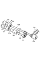
ところで、図3は、シート分離給送部132の駆動伝達系の構成を示す図である。プリンタ本体内に設置されている後述する図4に示す駆動モータからの駆動は、駆動ベルト233、電磁クラッチ235を介してフィードローラ130のローラ軸130aに伝達される。そして、ローラ軸103aへ伝えられた駆動は、タイミングベルト237を介して中継軸239へ伝えられ、更に、トルクリミッタ240を介してリタードローラ131のローラ軸131aへ伝えられる。
FIG. 3 is a diagram showing the configuration of the drive transmission system of the sheet separating and
ここで、給紙信号が入力されて給紙動作が開始されると、電磁クラッチ235がオンに制御される。これによって、フィードローラ130が給紙方向に回転駆動されると共に、リタードローラ131が反給紙方向に回転駆動される。これにより、ピックアップローラ129によって送り出された最上位のシート以外のシートSはリタードローラ131によって戻され、最上位のシート1枚のみが分離ニップ部Nに送り込まれるようになる。
Here, when a paper feed signal is input and a paper feed operation is started, the
シートが分離されて搬送ローラ対305a,305bに到達し、更に下流側へ送られる途中で、シートの後端がフィードローラ130とリタードローラ131との分離ニップ部Nに到達する前に、電磁クラッチ235がオフされる。シートは、搬送ローラ対305a,305bによって搬送され、フィードローラ130とリタードローラ131は搬送されるシートによって連れ回りして停止する。そして、次の給紙信号が入力されるまで停止し、給紙信号が入力されると、電磁クラッチがオンになって次のシートの給送動作が行われる。
Before the sheet reaches the separation nip N between the
また、図4は、シート分離給送部132の駆動を制御する制御ブロック図である。図4において、300は制御部であり、この制御部300には、給紙センサ304の検知信号及びタイマTからの計時情報が入力される。また、この制御部300は、給紙センサ304の検知信号及びタイマTからの計時情報に基づき電磁クラッチ235、駆動モータM1、ピックアップローラ昇降部232を駆動する。
FIG. 4 is a control block diagram for controlling the driving of the sheet separating and
ところで、既述したように装置の使用時間が多くなるにつれて、リタードローラ131の特定の部位において摩耗が進むようになる。そうすると、通常、電磁クラッチ235をオフしたときに、リタードローラ131はシートに連れ回りするが、摩耗が進んで、課題の欄で説明したように式(1)の状態となると、リタードローラ131はシートに連れ回りすることなく停止してしまう。そして、その摩耗が進んでしまった特定部位がシート分離給送時にシートに対向するとそこでリタードローラ131が停止してしまい、シート給送動作が終了すると、その特定部位がフィードローラ130と常に対向する状態となる。
By the way, as described above, as the usage time of the apparatus increases, wear proceeds at a specific portion of the
そして、既述したようにフィードローラ130は、例えばEPDMにより形成されており、リタードローラ131は、例えば硬度が低い材料であるウレタンにより形成されているため、表面がフィードローラ130に比べて硬度が低くなっている。
As described above, the
このため、リタードローラ131がフィードローラ130に圧接すると、リタードローラ131とフィードローラ130との間には、リタードローラ131の、フィードローラ130と接触している表面部が圧縮された状態で分離ニップ部Nが形成される。そして、例えば、プリンタの使用を停止する際、その特定の部位がフィードローラ130に圧接した状態でリタードローラ131が停止し、この圧接状態が長時間続くと、既述した図9に示すように、その特定の部位に大きなへこみが発生する。
For this reason, when the
そこで、摩耗が進んだ特定の部位がフィードローラ130に圧接した状態でリタードローラ131が停止した場合でも、特定の部位に局部的なへこみが形成されることがないよう、例えばジョブ終了後、フィードローラ130を所定量回転させるようにしている。そして、このようにフィードローラ130を所定量回転(後回転)させることにより、リタードローラ131は、その特定の部位がリタードローラ131に圧接することなく停止する。この結果、この後、プリンタを長時間停止させた場合でも、大きなへこみが形成されることはない。
Therefore, even when the
ここで、後回転時の所定量の回転は、リタードローラ131とフィードローラ130との圧接位置が、停止時のへこんだ状態の位置から少しずれた位置になるように設定すればよい。なお、位置を大きくずらすように回転の所定量を大きく設定すると、分離ニップ部Nまで送られている次のシートが分離ニップ部Nから大きく送り出されてしまう。この場合、カセットを引き出す時、大きく送り出されてしまったシートがプリンタ本体101に当たって破損するおそれがある。
Here, the predetermined amount of rotation during the post-rotation may be set so that the pressure contact position between the
そこで、本実施の形態においては、分離ニップ部Nの近傍に配置されている給紙センサ304がONした場合はすぐに回転を停止させるので、シートを送り過ぎてしまうことはなく、上述した問題を防止することができる。
Therefore, in the present embodiment, when the
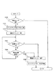
次に、このようなジョブ終了後におけるシート分離給送部132の後回転時の駆動制御について図5に示すフローチャート及び図6に示すタイミングチャートを用いて説明する。なお、本発明において、「ジョブ終了」とは、シート分離給送部132でのシートの分離給送動作が終了したことを含む。また、後回転は、電磁クラッチ237がオフになった後、最終シートの後端が分離ニップ部Nを抜けた後であれば画像形成部での画像形成動作が終了する前であってもよい。
Next, drive control at the time of post-rotation of the sheet separating and
ジョブが終了すると、まず制御部300は、給紙センサ304からの信号に基づきシートが給紙センサ304に達しているかを判断する。なお、本実施の形態においては、シートが給紙センサ304に達しているとき、センサレバー304aが押圧されることにより給紙センサ304はONとなるので、まず制御部300は、給紙センサ304がONか否かを判断する(S100)。
When the job ends, the
ここで、給紙センサ304がONであれば(S100のY)、シートは既に給紙センサ304に達しているのでフィードローラ130は後回転させない。一方、給紙センサ304がOFFであれば(S100のN)、フィードローラ130のローラ軸130aから駆動を受けて回転してシートを送ってしまわないように、ピックアップローラ昇降部232を駆動し、ピックアップローラ129を上昇させる(S101)。そして、このようにピックアップローラ129を上昇させ、ピックアップローラ129をシートから離間させることにより、フィードローラ130のローラ軸130aから駆動を受けてフィードローラ130が回転してもシートを送り出すことはない。
If the
次に、所定のタイミングで電磁クラッチをONし(S102)、フィードローラ130を所定時間回転させる。そして、このようにフィードローラ130が回転することにより、リタードローラ131を回転させる。次に、もしも、ジョブ終了後にすでにフィードローラ130にシートが噛まれていた場合は、回転によってシートが送り出されてしまう。そのため、図6の(a)に示すように、給紙センサ304が給送されたシートを検知してONとなると(S103のY)、電磁クラッチをOFFする(S104)。更に、この後、次のシート給送に備えて、ピックアップローラ昇降部232を駆動し、ピックアップローラ129を下降させる(S105)。
フィードローラ130を回転させても給紙センサ304がシートを検知せず、ONとならない場合には(S103のN)、タイマTからの計時情報に基づき所定時間、フィードローラ130を回転させる。例えば、分離ニップ部Nにシートがない場合には、図6の(b)に示すように、所定時間が経過しても(S106のY)、給紙センサ304がシートを検知しない。そして、電磁クラッチをOFFする(S104)。更に、この後、次のシート給送に備えて、ピックアップローラ昇降部232を駆動し、ピックアップローラ129を下降させる(S105)。
Next, the electromagnetic clutch is turned on at a predetermined timing (S102), and the
If the
このように、本実施の形態によれば、ジョブ終了後、フィードローラ130を所定量の後回転をさせ、リタードローラ131を回転させることにより、リタードローラ131のフィードローラ130との圧接位置を変更することができる。これにより、リタードローラ131が、特定の部位が、常にフィードローラ130に圧接した状態で停止するのを防ぐことができる。この結果、リタードローラ131のへこみの発生を防ぐことができ、シートを安定して分離給送することができる。さらに、リタードローラ131の寿命を延ばすことができ、コストの低減を図ることができる。
Thus, according to the present embodiment, after the job is completed, the
なお、本実施の形態では、ピックアップローラによりカセットからシートを送り出してフィードローラとリタードローラとの間でシートを一枚ずつ分離するリタードローラ分離方式に適用した場合に付いて説明したが、本発明はこれに限定されるものではない。例えば、ピックアップローラの用いずに、フィードローラによりカセットからシートを送り出すと共に、フィードローラに圧接されているリタードローラによりシートを分離すリタードローラ分離方式に適用してもよい。 Although the present embodiment has been described with respect to the case where the present invention is applied to a retard roller separation system in which a sheet is fed from a cassette by a pickup roller and the sheets are separated one by one between a feed roller and a retard roller, the present invention has been described. Is not limited to this. For example, the present invention may be applied to a retard roller separation method in which a sheet is fed from a cassette by a feed roller without using a pickup roller, and the sheet is separated by a retard roller pressed against the feed roller.
51〜54 シート給送装置
51a〜54a カセット
55 画像形成部
100 プリンタ
129 ピックアップローラ
130 フィードローラ
131 リタードローラ
132 シート分離給送部
235 電磁クラッチ
300 制御部
304 給紙センサ
S シート
51 to 54
Claims (5)
前記シート分離給送部は、
シートを給送する方向に回転する給送ローラと、
シートを給送する方向と逆方向に回転可能に設けられ、前記給送ローラに圧接して前記給送ローラとの間でシートを1枚ずつ分離する分離ニップ部を形成し、かつ前記給送ローラに対して追従回転可能な分離ローラと、を備え、
ジョブ終了後、前記分離ローラを回転させるように前記給送ローラを所定量回転させることを特徴とするシート給送装置。 In a sheet feeding apparatus provided with a sheet separating and feeding unit that separates and feeds the sheets stored in the sheet storage unit one by one,
The sheet separating and feeding unit is
A feeding roller that rotates in the direction of feeding the sheet;
A separation nip portion that is provided so as to be rotatable in the direction opposite to the sheet feeding direction, presses against the feeding roller and separates the sheets one by one from the feeding roller, and the feeding A separation roller capable of following and rotating with respect to the roller,
A sheet feeding apparatus that rotates the feeding roller by a predetermined amount so as to rotate the separation roller after the job is finished.
ジョブ終了後、前記検知部がシートを検知していた場合は前記給送ローラに所定量回転をさせず、検知していない場合でも、前記給送ローラを所定量回転させている途中にシートを検知した場合は、回転を停止させることを特徴とする請求項1記載のシート給送装置。 Provided on the downstream side of the sheet separating and feeding unit in the sheet feeding direction, and provided with a detecting unit for detecting the sheet fed by the sheet separating and feeding unit,
After the job is finished, if the detection unit detects a sheet, the feeding roller is not rotated by a predetermined amount, and even if it is not detected, the sheet is rotated while the feeding roller is rotated by a predetermined amount. 2. The sheet feeding apparatus according to claim 1, wherein the rotation is stopped when detected.
前記シート給送装置から送り出されたシートに画像を形成する画像形成部と、を備えたことを特徴とする画像形成装置。 The sheet feeding device according to any one of claims 1 to 4,
An image forming apparatus comprising: an image forming unit that forms an image on a sheet fed from the sheet feeding device.
Priority Applications (2)
| Application Number | Priority Date | Filing Date | Title |
|---|---|---|---|
| JP2008206041A JP5213579B2 (en) | 2008-08-08 | 2008-08-08 | Sheet feeding apparatus and image forming apparatus |
| US12/507,982 US8246039B2 (en) | 2008-08-08 | 2009-07-23 | Sheet feeding apparatus and image forming apparatus |
Applications Claiming Priority (1)
| Application Number | Priority Date | Filing Date | Title |
|---|---|---|---|
| JP2008206041A JP5213579B2 (en) | 2008-08-08 | 2008-08-08 | Sheet feeding apparatus and image forming apparatus |
Publications (3)
| Publication Number | Publication Date |
|---|---|
| JP2010042873A true JP2010042873A (en) | 2010-02-25 |
| JP2010042873A5 JP2010042873A5 (en) | 2011-09-22 |
| JP5213579B2 JP5213579B2 (en) | 2013-06-19 |
Family
ID=41652177
Family Applications (1)
| Application Number | Title | Priority Date | Filing Date |
|---|---|---|---|
| JP2008206041A Expired - Fee Related JP5213579B2 (en) | 2008-08-08 | 2008-08-08 | Sheet feeding apparatus and image forming apparatus |
Country Status (2)
| Country | Link |
|---|---|
| US (1) | US8246039B2 (en) |
| JP (1) | JP5213579B2 (en) |
Cited By (1)
| Publication number | Priority date | Publication date | Assignee | Title |
|---|---|---|---|---|
| JP2014148394A (en) * | 2013-02-01 | 2014-08-21 | Shinko Seisakusho Co Ltd | Bill arrangement device |
Families Citing this family (8)
| Publication number | Priority date | Publication date | Assignee | Title |
|---|---|---|---|---|
| JP5229266B2 (en) * | 2010-04-28 | 2013-07-03 | ブラザー工業株式会社 | Paper feeding device and recording device |
| JP5780749B2 (en) | 2010-12-17 | 2015-09-16 | キヤノン株式会社 | Sheet feeding apparatus and image forming apparatus |
| JP5780793B2 (en) * | 2011-03-24 | 2015-09-16 | キヤノン株式会社 | Sheet feeding apparatus and image forming apparatus |
| US8573585B1 (en) * | 2012-05-30 | 2013-11-05 | Hewlett-Packard Development Company, L.P. | Media handling system |
| JP5868365B2 (en) | 2013-09-18 | 2016-02-24 | キヤノン株式会社 | Image forming apparatus |
| JP2016005986A (en) | 2014-05-29 | 2016-01-14 | キヤノン株式会社 | Sheet feeder and image forming apparatus |
| JP6344300B2 (en) * | 2015-04-28 | 2018-06-20 | 京セラドキュメントソリューションズ株式会社 | Paper feeding device and image forming apparatus |
| JP2022048821A (en) | 2020-09-15 | 2022-03-28 | キヤノン株式会社 | Sheet detection device and image formation device |
Citations (3)
| Publication number | Priority date | Publication date | Assignee | Title |
|---|---|---|---|---|
| JPH07117880A (en) * | 1993-10-28 | 1995-05-09 | Canon Inc | Sheet material supply device and image forming device |
| JPH0822168A (en) * | 1994-07-07 | 1996-01-23 | Canon Inc | Image forming device |
| JP2000211753A (en) * | 1999-01-20 | 2000-08-02 | Canon Inc | Sheet feeding device and image forming device provided with the device |
Family Cites Families (13)
| Publication number | Priority date | Publication date | Assignee | Title |
|---|---|---|---|---|
| US4844638A (en) * | 1987-02-17 | 1989-07-04 | Brother Kogyo Kabushiki Kaisha | Paper feeder for a printer |
| US5072924A (en) * | 1989-05-29 | 1991-12-17 | Mita Industrial Co., Ltd. | Paper feeding control device |
| US5199696A (en) * | 1990-06-19 | 1993-04-06 | Konica Corporation | Paper feeding unit |
| JPH05338837A (en) | 1992-06-04 | 1993-12-21 | Ricoh Co Ltd | Paper feeding device |
| US5478066A (en) | 1992-11-02 | 1995-12-26 | Canon Kabushiki Kaisha | Sheet supply apparatus |
| JP3097889B2 (en) | 1993-10-01 | 2000-10-10 | キヤノン株式会社 | Sheet feeding apparatus and image forming apparatus |
| US5722652A (en) | 1993-10-28 | 1998-03-03 | Canon Kabushiki Kaisha | Sheet feeding apparatus with sheet absorb means and a conveyor controlled for forward and reverse conveying directions |
| US6651980B2 (en) | 2001-06-13 | 2003-11-25 | Canon Kabushiki Kaisha | Sheet conveying apparatus with correction device to compensate for sheet interval variation |
| JP3697217B2 (en) | 2002-03-08 | 2005-09-21 | キヤノン株式会社 | Image forming apparatus |
| JP4261826B2 (en) | 2002-06-12 | 2009-04-30 | キヤノン株式会社 | Image forming apparatus |
| US6955348B2 (en) | 2002-09-20 | 2005-10-18 | Canon Kabushiki Kaisha | Sheet feeder which separates sheets with variable speed and/or direction blown air and image forming apparatus using same |
| JP4062694B2 (en) * | 2003-04-23 | 2008-03-19 | 株式会社リコー | Sheet conveying apparatus and image forming apparatus |
| JP5116344B2 (en) | 2007-04-03 | 2013-01-09 | キヤノン株式会社 | Image forming apparatus |
-
2008
- 2008-08-08 JP JP2008206041A patent/JP5213579B2/en not_active Expired - Fee Related
-
2009
- 2009-07-23 US US12/507,982 patent/US8246039B2/en not_active Expired - Fee Related
Patent Citations (3)
| Publication number | Priority date | Publication date | Assignee | Title |
|---|---|---|---|---|
| JPH07117880A (en) * | 1993-10-28 | 1995-05-09 | Canon Inc | Sheet material supply device and image forming device |
| JPH0822168A (en) * | 1994-07-07 | 1996-01-23 | Canon Inc | Image forming device |
| JP2000211753A (en) * | 1999-01-20 | 2000-08-02 | Canon Inc | Sheet feeding device and image forming device provided with the device |
Cited By (1)
| Publication number | Priority date | Publication date | Assignee | Title |
|---|---|---|---|---|
| JP2014148394A (en) * | 2013-02-01 | 2014-08-21 | Shinko Seisakusho Co Ltd | Bill arrangement device |
Also Published As
| Publication number | Publication date |
|---|---|
| US20100032893A1 (en) | 2010-02-11 |
| US8246039B2 (en) | 2012-08-21 |
| JP5213579B2 (en) | 2013-06-19 |
Similar Documents
| Publication | Publication Date | Title |
|---|---|---|
| JP5213579B2 (en) | Sheet feeding apparatus and image forming apparatus | |
| US9873576B2 (en) | Sheet feeding apparatus and image forming apparatus | |
| JP2007217092A (en) | Sheet feeder and image forming device | |
| US20100278572A1 (en) | Sheet conveying apparatus and image forming apparatus | |
| US7770881B2 (en) | Sheet material feeding device having a sheet guide part | |
| JP4120636B2 (en) | Paper feeder | |
| JP2007168955A (en) | Image forming device and carrying device | |
| US10589948B2 (en) | Sheet feeding apparatus | |
| JP5780749B2 (en) | Sheet feeding apparatus and image forming apparatus | |
| CN108008610B (en) | Sheet feeding apparatus and image forming apparatus | |
| GB2487660A (en) | Multi-feed detection and control system | |
| JP2020075820A (en) | Sheet feeder | |
| JP5153285B2 (en) | Image forming apparatus | |
| US8523172B2 (en) | Image forming apparatus | |
| JP7019386B2 (en) | Sheet feeding device and image forming device | |
| US11708234B2 (en) | Sheet conveying device and image forming apparatus incorporating the sheet conveying device | |
| JP2003155130A (en) | Image forming device | |
| JP2005082340A (en) | Image formation device | |
| JP4072796B2 (en) | Image forming apparatus | |
| JP6045324B2 (en) | Sheet feeding apparatus and image forming apparatus | |
| JP6862673B2 (en) | Paper feed device and image forming device | |
| JP5303942B2 (en) | RECORDING MEDIUM CONVEYING DEVICE, TRANSFER DEVICE, AND IMAGE FORMING DEVICE | |
| JP2006248646A (en) | Medium conveying device, and image forming device | |
| US9981818B2 (en) | Image forming apparatus | |
| JP4977581B2 (en) | Sheet separating / conveying mechanism, sheet conveying apparatus including the same, and image forming apparatus |
Legal Events
| Date | Code | Title | Description |
|---|---|---|---|
| A521 | Written amendment |
Free format text: JAPANESE INTERMEDIATE CODE: A523 Effective date: 20110804 |
|
| A621 | Written request for application examination |
Free format text: JAPANESE INTERMEDIATE CODE: A621 Effective date: 20110804 |
|
| RD05 | Notification of revocation of power of attorney |
Free format text: JAPANESE INTERMEDIATE CODE: A7425 Effective date: 20120125 |
|
| RD03 | Notification of appointment of power of attorney |
Free format text: JAPANESE INTERMEDIATE CODE: A7423 Effective date: 20120203 |
|
| A977 | Report on retrieval |
Free format text: JAPANESE INTERMEDIATE CODE: A971007 Effective date: 20121011 |
|
| A131 | Notification of reasons for refusal |
Free format text: JAPANESE INTERMEDIATE CODE: A131 Effective date: 20121016 |
|
| A521 | Written amendment |
Free format text: JAPANESE INTERMEDIATE CODE: A523 Effective date: 20121217 |
|
| TRDD | Decision of grant or rejection written | ||
| A01 | Written decision to grant a patent or to grant a registration (utility model) |
Free format text: JAPANESE INTERMEDIATE CODE: A01 Effective date: 20130129 |
|
| A61 | First payment of annual fees (during grant procedure) |
Free format text: JAPANESE INTERMEDIATE CODE: A61 Effective date: 20130226 |
|
| R151 | Written notification of patent or utility model registration |
Ref document number: 5213579 Country of ref document: JP Free format text: JAPANESE INTERMEDIATE CODE: R151 |
|
| FPAY | Renewal fee payment (event date is renewal date of database) |
Free format text: PAYMENT UNTIL: 20160308 Year of fee payment: 3 |
|
| LAPS | Cancellation because of no payment of annual fees |