JP2010042765A - Pneumatic tire - Google Patents
Pneumatic tire Download PDFInfo
- Publication number
- JP2010042765A JP2010042765A JP2008208883A JP2008208883A JP2010042765A JP 2010042765 A JP2010042765 A JP 2010042765A JP 2008208883 A JP2008208883 A JP 2008208883A JP 2008208883 A JP2008208883 A JP 2008208883A JP 2010042765 A JP2010042765 A JP 2010042765A
- Authority
- JP
- Japan
- Prior art keywords
- sipe
- tire
- pneumatic tire
- segment
- width direction
- Prior art date
- Legal status (The legal status is an assumption and is not a legal conclusion. Google has not performed a legal analysis and makes no representation as to the accuracy of the status listed.)
- Granted
Links
- 239000002131 composite material Substances 0.000 claims description 27
- 238000005096 rolling process Methods 0.000 abstract description 50
- 230000006866 deterioration Effects 0.000 abstract 1
- 230000002401 inhibitory effect Effects 0.000 abstract 1
- 230000000694 effects Effects 0.000 description 20
- 230000000052 comparative effect Effects 0.000 description 13
- 238000011156 evaluation Methods 0.000 description 5
- 238000012986 modification Methods 0.000 description 4
- 230000004048 modification Effects 0.000 description 4
- 150000001875 compounds Chemical class 0.000 description 3
- 238000012360 testing method Methods 0.000 description 3
- 238000011161 development Methods 0.000 description 2
- 238000000034 method Methods 0.000 description 2
- 230000009466 transformation Effects 0.000 description 2
- 230000001154 acute effect Effects 0.000 description 1
- 238000013459 approach Methods 0.000 description 1
- 238000005452 bending Methods 0.000 description 1
- 238000004891 communication Methods 0.000 description 1
- 230000007547 defect Effects 0.000 description 1
- 238000006073 displacement reaction Methods 0.000 description 1
- 230000007613 environmental effect Effects 0.000 description 1
- 238000012423 maintenance Methods 0.000 description 1
- 230000001737 promoting effect Effects 0.000 description 1
Images


Classifications
-
- Y—GENERAL TAGGING OF NEW TECHNOLOGICAL DEVELOPMENTS; GENERAL TAGGING OF CROSS-SECTIONAL TECHNOLOGIES SPANNING OVER SEVERAL SECTIONS OF THE IPC; TECHNICAL SUBJECTS COVERED BY FORMER USPC CROSS-REFERENCE ART COLLECTIONS [XRACs] AND DIGESTS
- Y02—TECHNOLOGIES OR APPLICATIONS FOR MITIGATION OR ADAPTATION AGAINST CLIMATE CHANGE
- Y02T—CLIMATE CHANGE MITIGATION TECHNOLOGIES RELATED TO TRANSPORTATION
- Y02T10/00—Road transport of goods or passengers
- Y02T10/80—Technologies aiming to reduce greenhouse gasses emissions common to all road transportation technologies
- Y02T10/86—Optimisation of rolling resistance, e.g. weight reduction
Abstract
Description
本発明は、環境への負荷の低減に有効な空気入りタイヤに関し、更に詳しくは、操縦安定性の低下を抑制しながら転がり抵抗を低減することを可能にした空気入りタイヤに関する。 The present invention relates to a pneumatic tire that is effective in reducing the load on the environment, and more particularly to a pneumatic tire that can reduce rolling resistance while suppressing a decrease in steering stability.
近年、空気入りタイヤにおいて、環境への負荷の低減が求められており、特に定速走行での転がり抵抗の更なる低減が求められている。通常、転がり抵抗を低減する場合、ヒステリシスロスの低いトレッドゴムを用いる手法が採られるが、このような手法ではグリップ力の低下を招くため操縦安定性が低下する傾向がある。 In recent years, in pneumatic tires, there has been a demand for a reduction in environmental load, and in particular, there has been a demand for further reduction in rolling resistance at a constant speed. Usually, when rolling resistance is reduced, a technique using a tread rubber having a low hysteresis loss is employed. However, in such a technique, the gripping force is lowered, and thus the steering stability tends to be lowered.
これに対して、トレッド部においてタイヤ幅方向に延長するラグ溝の底部に該ラグ溝の長手方向に沿ってサイプを形成することにより、トレッドゴムの引張り変形を抑制し、それによって転がり抵抗を低減することが提案されている(例えば、特許文献1参照)。 On the other hand, by forming a sipe along the longitudinal direction of the lug groove at the bottom of the lug groove extending in the tire width direction in the tread portion, the tensile deformation of the tread rubber is suppressed, thereby reducing rolling resistance. It has been proposed (see, for example, Patent Document 1).
しかしながら、ラグ溝の底部にサイプを形成した場合、陸部がタイヤ周方向に分断されるため、横方向の入力を支える能力が低下し、それが操縦安定性の低下要因となる。そのため、操縦安定性の維持と転がり抵抗の低減とを両立することは困難である。
本発明の目的は、操縦安定性の低下を抑制しながら転がり抵抗を低減することを可能にした空気入りタイヤを提供することにある。 An object of the present invention is to provide a pneumatic tire that can reduce rolling resistance while suppressing a decrease in steering stability.
上記目的を達成するための本発明の空気入りタイヤは、トレッド部にタイヤ周方向に延びる複数本の周方向溝を設け、これら周方向溝により複数列の陸部を区画した空気入りタイヤにおいて、少なくとも1列の陸部にタイヤ幅方向に延びる複数本のサイプを設け、これらサイプをトレッド表面ではジグザグ状又は波状となる部分を含み底部では実質的に直線状に収束した3次元構造とし、かつ、前記サイプのトレッド表面での延長方向と底部での延長方向とを互いに交差する関係にしたことを特徴とするものである。 The pneumatic tire of the present invention for achieving the above object is a pneumatic tire in which a plurality of circumferential grooves extending in the tire circumferential direction are provided in a tread portion, and a plurality of rows of land portions are partitioned by the circumferential grooves. A plurality of sipes extending in the tire width direction are provided in at least one row of land portions, and these sipes have a three-dimensional structure that includes a zigzag or wavy portion on the tread surface and converges substantially linearly at the bottom, and The extending direction at the tread surface of the sipe and the extending direction at the bottom part intersect each other.
また、上記目的を達成するための本発明の他の空気入りタイヤは、トレッド部にタイヤ周方向に延びる複数本の周方向溝を設け、これら周方向溝により複数列の陸部を区画した空気入りタイヤにおいて、少なくとも1列の陸部にタイヤ幅方向に延びるラグ溝とサイプとを連結してなる複数本の複合溝を設け、前記サイプをトレッド表面ではジグザグ状又は波状となる部分を含み底部では実質的に直線状に収束した3次元構造とし、かつ、前記サイプのトレッド表面での延長方向と底部での延長方向とを互いに交差する関係にしたことを特徴とするものである。 In another pneumatic tire of the present invention for achieving the above object, a plurality of circumferential grooves extending in the tire circumferential direction are provided in a tread portion, and a plurality of rows of land portions are partitioned by the circumferential grooves. In a tire, a plurality of compound grooves formed by connecting lug grooves extending in the tire width direction and sipes are provided in at least one row of land portions, and the sipes include a zigzag or wavy portion on the tread surface. Then, the three-dimensional structure converges substantially linearly, and the extending direction on the tread surface of the sipe and the extending direction on the bottom part intersect each other.
本発明では、サイプをトレッド表面ではジグザグ状又は波状となる部分を含み底部では実質的に直線状に収束した3次元構造としているので、タイヤが転動する際の踏み込み時と蹴り出し時におけるトレッド部のタイヤ周方向の曲率変化に対して、サイプが底部から開口して陸部の微細な屈曲を許容するので、トレッドゴムのタイヤ周方向の引張り変形を抑制し、それによって転がり抵抗を低減することができる。また、サイプはトレッド表面ではジグザグ状又は波状となる部分を含み、かつサイプのトレッド表面での延長方向と底部での延長方向とが互いに交差する関係にあるので、横方向の入力に対して陸部の倒れ込みを抑制し、操縦安定性を十分に確保することが可能となる。 In the present invention, since the sipe has a three-dimensional structure that includes a zigzag or wavy portion on the tread surface and converges substantially linearly at the bottom, the tread at the time of stepping and kicking when the tire rolls Because the sipe opens from the bottom and allows fine bending of the land with respect to the change in curvature of the tire in the tire circumferential direction, it suppresses the tensile deformation in the tire circumferential direction of the tread rubber, thereby reducing the rolling resistance be able to. In addition, the sipe includes a zigzag or wavy portion on the tread surface, and the extension direction on the tread surface of the sipe and the extension direction on the bottom intersect each other, so that the sipe has a It is possible to suppress the falling of the part and to ensure sufficient steering stability.
本発明において、上記3次元構造を有するサイプは陸部に対して単独で設けても良く、或いは、ラグ溝とサイプとを連結してなる複合溝として設けても良い。 In the present invention, the sipe having the above three-dimensional structure may be provided alone with respect to the land portion, or may be provided as a composite groove formed by connecting a lug groove and a sipe.
上記3次元構造を有するサイプを陸部に対して単独で設ける場合、以下の構成を採用することが望ましい。即ち、サイプはタイヤ幅方向の最外側に位置するショルダー陸部に配置し、該ショルダー陸部においてサイプの一端を内側の周方向溝に連通させる一方で他端を接地端の外側まで延長させることが好ましい。タイヤ転動時におけるトレッド部の曲率変化が最も大きいショルダー陸部に上記サイプを配置することにより、転がり抵抗を効果的に低減することができる。また、サイプはショルダー陸部の内側に位置する中間陸部に配置し、該中間陸部においてサイプの両端をそれぞれ両側の周方向溝に連通させることが好ましい。これにより、ショルダー陸部の変形を促進し、転がり抵抗の低減効果を高めることができる。更に、サイプは車両装着時における少なくとも車両内側のショルダー陸部に配置することが好ましい。通常、車両にはネガティブキャンバーが設定されており、車両内側のショルダー陸部の転がり抵抗に対する寄与が大きいため、その部分に上記サイプを配置することにより、転がり抵抗の低減効果を高めることができる。 When the sipe having the three-dimensional structure is provided independently for the land portion, it is desirable to adopt the following configuration. That is, the sipe is arranged on the shoulder land portion located on the outermost side in the tire width direction, and one end of the sipe is communicated with the inner circumferential groove in the shoulder land portion, while the other end is extended to the outside of the ground contact end. Is preferred. By disposing the sipe in the shoulder land portion where the change in curvature of the tread portion at the time of tire rolling is the largest, the rolling resistance can be effectively reduced. Further, it is preferable that the sipe is disposed in an intermediate land portion located inside the shoulder land portion, and the both ends of the sipe communicate with the circumferential grooves on both sides in the intermediate land portion. Thereby, a deformation | transformation of a shoulder land part can be accelerated | stimulated and the reduction effect of rolling resistance can be heightened. Furthermore, the sipe is preferably disposed at least on the shoulder land portion inside the vehicle when the vehicle is mounted. Normally, a negative camber is set in the vehicle, and the contribution to the rolling resistance of the shoulder land portion inside the vehicle is large. Therefore, the effect of reducing rolling resistance can be enhanced by arranging the sipe in that portion.
サイプのトレッド表面でのタイヤ幅方向の長さW0に対してジグザグ状又は波状となる部分のトレッド表面でのタイヤ幅方向の長さW1はW1/W0=0.40〜0.80の関係にすることが好ましい。これにより、操縦安定性を十分に確保し、かつブロック欠けを防止することができる。 The length W1 in the tire width direction on the tread surface of the zigzag or corrugated portion with respect to the length W0 in the tire width direction on the sipe tread surface has a relationship of W1 / W0 = 0.40-0.80. It is preferable to do. As a result, it is possible to ensure sufficient steering stability and prevent block chipping.
サイプはトレッド表面においてタイヤ幅方向中央側に位置する第1分節とタイヤ幅方向外側に位置する第2分節とを繰り返してなるジグザグ状に形成し、これら第1分節と第2分節のタイヤ周方向に対する傾斜角度を互いに異ならせ、第1分節の傾斜角度を30°〜70°の範囲に設定すると共に第2分節の傾斜角度を−30°〜10°の範囲に設定することが好ましい。この場合、タイヤ周方向に対する傾斜角度が比較的大きい第1分節によりサイプを開き易くするためトレッドゴムの引張り変形を抑制し、その一方で、タイヤ周方向に対する傾斜角度が比較的小さい第2分節により横方向の入力を効果的に支持することを可能にし、操縦安定性の低下を抑制することができる。 The sipe is formed in a zigzag shape formed by repeating a first segment located on the tire width direction center side on the tread surface and a second segment located on the outer side in the tire width direction, and the tire circumferential direction of the first segment and the second segment. It is preferable that the inclination angle of the first segment is set in the range of 30 ° to 70 ° and the inclination angle of the second segment is set in the range of −30 ° to 10 °. In this case, the first segment having a relatively large inclination angle with respect to the tire circumferential direction suppresses the tensile deformation of the tread rubber so that the sipe can be easily opened, while the second segment has a relatively small inclination angle with respect to the tire circumferential direction. It is possible to effectively support lateral input, and it is possible to suppress a decrease in steering stability.
サイプの少なくとも周方向溝に連通する位置での深さは該周方向溝の最大深さの70%〜100%の範囲に設定することが好ましい。これにより、転がり抵抗の低減効果を最大限に発揮することが可能になる。 The depth of the sipe at a position communicating with at least the circumferential groove is preferably set in a range of 70% to 100% of the maximum depth of the circumferential groove. This makes it possible to maximize the rolling resistance reduction effect.
サイプの底部での延長方向はタイヤ周方向に対して80°〜100°の範囲に設定し、サイプのトレッド表面での延長方向は該サイプの底部での延長方向に対して20°〜50°の範囲に設定することが好ましい。これにより、転がり抵抗の低減効果を最大限に発揮することが可能になる。 The extension direction at the bottom of the sipe is set in a range of 80 ° to 100 ° with respect to the tire circumferential direction, and the extension direction at the tread surface of the sipe is 20 ° to 50 ° with respect to the extension direction at the bottom of the sipe. It is preferable to set in the range. This makes it possible to maximize the rolling resistance reduction effect.
一方、上記3次元構造を有するサイプを陸部に対してラグ溝とサイプとを連結してなる複合溝として設ける場合、以下の構成を採用することが望ましい。即ち、複合溝はタイヤ幅方向の最外側に位置するショルダー陸部に配置し、該ショルダー陸部において複合溝のサイプ側の端部を内側の周方向溝に連通させる一方でラグ溝側の端部を接地端の外側まで延長させることが好ましい。タイヤ転動時におけるトレッド部の曲率変化が最も大きいショルダー陸部に上記複合溝を配置することにより、転がり抵抗を効果的に低減することができる。また、複合溝はショルダー陸部の内側に位置する中間陸部に配置し、該中間陸部において複合溝の両端をそれぞれ両側の周方向溝に連通させたことが好ましい。これにより、ショルダー陸部の変形を促進し、転がり抵抗の低減効果を高めることができる。更に、複合溝は車両装着時における少なくとも車両内側のショルダー陸部に配置することが好ましい。通常、車両にはネガティブキャンバーが設定されており、車両内側のショルダー陸部の転がり抵抗に対する寄与が大きいため、その部分に上記複合溝を配置することにより、転がり抵抗の低減効果を高めることができる。 On the other hand, when the sipe having the above three-dimensional structure is provided as a composite groove formed by connecting a lug groove and a sipe to the land portion, it is desirable to adopt the following configuration. That is, the composite groove is disposed in the shoulder land portion located on the outermost side in the tire width direction, and the end on the sipe side of the composite groove is communicated with the inner circumferential groove in the shoulder land portion, while the end on the lug groove side. It is preferable to extend the portion to the outside of the ground end. By disposing the composite groove in the shoulder land portion where the curvature change of the tread portion during tire rolling is greatest, the rolling resistance can be effectively reduced. Preferably, the composite groove is disposed in an intermediate land portion located inside the shoulder land portion, and both ends of the composite groove are communicated with the circumferential grooves on both sides in the intermediate land portion. Thereby, a deformation | transformation of a shoulder land part can be accelerated | stimulated and the reduction effect of rolling resistance can be heightened. Furthermore, it is preferable that the composite groove is disposed at least on the shoulder land portion inside the vehicle when the vehicle is mounted. Usually, a negative camber is set in a vehicle, and the contribution to the rolling resistance of the shoulder land portion inside the vehicle is large. Therefore, the effect of reducing rolling resistance can be enhanced by arranging the composite groove in that portion. .
ショルダー陸部の接地領域内でのタイヤ幅方向の長さW10に対してラグ溝の接地領域内でのタイヤ幅方向の長さW11はW11/W10=0.40〜0.80の関係にすることが好ましい。これにより、操縦安定性を確保すると共に、排水性を確保することができる。 The length W11 in the tire width direction in the ground contact region of the lug groove is in the relationship of W11 / W10 = 0.40-0.80 with respect to the length W10 in the tire width direction in the ground contact region of the shoulder land portion. It is preferable. Thereby, while ensuring steering stability, drainage can be ensured.
サイプはトレッド表面においてタイヤ幅方向中央側に位置する第1分節とタイヤ幅方向外側に位置する第2分節とを繰り返してなるジグザグ状に形成し、これら第1分節と第2分節のタイヤ周方向に対する傾斜角度を互いに異ならせ、前記第1分節の傾斜角度を30°〜70°の範囲に設定すると共に前記第2分節の傾斜角度を−30°〜10°の範囲に設定することが好ましい。この場合、タイヤ周方向に対する傾斜角度が比較的大きい第1分節によりサイプを開き易くするためトレッドゴムの引張り変形を抑制し、その一方で、タイヤ周方向に対する傾斜角度が比較的小さい第2分節により横方向の入力を効果的に支持することを可能にし、操縦安定性の低下を抑制することができる。 The sipe is formed in a zigzag shape in which a first segment located on the tire width direction center side and a second segment located on the outer side in the tire width direction are repeated on the tread surface, and the tire circumferential direction of these first segment and second segment It is preferable that the inclination angle of the first segment is set in a range of 30 ° to 70 ° and the inclination angle of the second segment is set in a range of −30 ° to 10 °. In this case, the first segment having a relatively large inclination angle with respect to the tire circumferential direction suppresses the tensile deformation of the tread rubber so that the sipe can be easily opened, while the second segment has a relatively small inclination angle with respect to the tire circumferential direction. It is possible to effectively support lateral input, and it is possible to suppress a decrease in steering stability.
サイプの深さはそれに繋がるラグ溝の最大深さの80%〜100%の範囲に設定することが好ましい。これにより、転がり抵抗の低減効果を最大限に発揮することが可能になる。 The depth of the sipe is preferably set in the range of 80% to 100% of the maximum depth of the lug groove connected to it. This makes it possible to maximize the rolling resistance reduction effect.
サイプの底部での延長方向はタイヤ周方向に対して80°〜100°の範囲に設定し、サイプのトレッド表面での延長方向を該サイプの底部での延長方向に対して20°〜50°の範囲に設定することが好ましい。これにより、転がり抵抗の低減効果を最大限に発揮することが可能になる。 The extension direction at the bottom of the sipe is set in a range of 80 ° to 100 ° with respect to the tire circumferential direction, and the extension direction at the tread surface of the sipe is set to 20 ° to 50 ° with respect to the extension direction at the bottom of the sipe. It is preferable to set in the range. This makes it possible to maximize the rolling resistance reduction effect.
本発明において、接地領域とはタイヤが基づく規格(JATMA、TRA、ETRTO)にてタイヤ毎に規定される最大負荷能力に対応する空気圧(最高空気圧)をタイヤに充填し、該タイヤをトレッド部が接地するように平面上に配置して最大負荷能力の80%の荷重を掛けたときの接地領域である。また、接地端とは当該接地領域のタイヤ軸方向の外端である。 In the present invention, the contact area is filled with air pressure (maximum air pressure) corresponding to the maximum load capacity defined for each tire in the standards (JATMA, TRA, ETRTO) on which the tire is based. This is a grounding region when a load of 80% of the maximum load capacity is applied on a plane so as to be grounded. The ground contact end is an outer end of the ground contact region in the tire axial direction.
以下、本発明の構成について添付の図面を参照しながら詳細に説明する。図1は本発明の実施形態からなる空気入りタイヤのトレッドパターンのタイヤ赤道線CLを境とする片側を示す展開図である。図2は図1のサイプを示す拡大図である。 Hereinafter, the configuration of the present invention will be described in detail with reference to the accompanying drawings. FIG. 1 is a developed view showing one side of a tread pattern of a pneumatic tire according to an embodiment of the present invention, with a tire equator line CL as a boundary. FIG. 2 is an enlarged view showing the sipe of FIG.
図1に示すように、トレッド部Tにはタイヤ周方向に延びる複数本の周方向溝1〜3が形成され、これら周方向溝1〜3により複数列の陸部10,20,30が区画されている。より具体的には、タイヤ赤道線CLに最も近いセンター陸部10と、該センター陸部10の外側に位置する中間陸部20と、該中間陸部20の外側に位置するショルダー陸部30である。なお、タイヤ赤道線CL上に位置する周方向溝1と最もショルダー側に位置する周方向溝3は、溝幅が3mm〜25mmで溝深さが7mm〜13mmである主溝に相当するものである。
As shown in FIG. 1, a plurality of circumferential grooves 1 to 3 extending in the tire circumferential direction are formed in the tread portion T, and a plurality of rows of
センター陸部10には、タイヤ幅方向に延びる複数本のラグ溝11が形成され、これらラグ溝11により複数のブロック12が区分されている。ラグ溝11のセンター側の部分には底上げ部11aが形成されている。また、ブロック12の鋭角の角部には面取り部12aが形成されている。
A plurality of
中間陸部20には、タイヤ幅方向に延びる複数本のラグ溝21が形成され、これらラグ溝21により複数のブロック22が区分されている。ラグ溝21はラグ溝11の延長線上に配置されている。
A plurality of
ショルダー陸部30には、タイヤ幅方向に延びる複数本のラグ溝31が形成されている。これらラグ溝31は接地端Eの内側から外側まで延長し、内側の端部が周方向溝3に対して非連通であり、外側の端部がタイヤ周方向に屈曲している。また、ショルダー陸部30には、タイヤ幅方向に延びる複数本のサイプ33が形成されている。これらサイプ33は、一端が内側の周方向溝3に連通し、他端が接地端Eの外側まで延長している。サイプ33は、トレッド表面ではジグザグ状又は波状となる部分を含み底部では実質的に直線状に収束した3次元構造を有している(図2参照)。しかも、サイプ33のトレッド表面での延長方向と底部での延長方向は互いに交差する関係になっている。なお、サイプ33のトレッド表面での延長方向とは、ジグザグ状又は波状となる部分及びその両側の直線状部分を含むサイプ全体が延長する方向であり、例えば、直線状部分の延長方向である。
A plurality of
上記空気入りタイヤでは、サイプ33をトレッド表面ではジグザグ状又は波状となる部分を含み底部では実質的に直線状に収束した3次元構造としているので、図3に示すように、タイヤが転動する際の踏み込み時と蹴り出し時において、トレッド部Tのタイヤ周方向の曲率変化に対して、サイプ33が底部を基点として開口してショルダー陸部30の微細な屈曲を許容する。そのため、トレッドゴムのタイヤ周方向の引張り変形を抑制し、それによって転がり抵抗を低減することができる。特に、タイヤ転動時におけるトレッド部Tの曲率変化が最も大きいショルダー陸部30にサイプ33を配置することにより、転がり抵抗を効果的に低減することができる。
In the pneumatic tire, the
ショルダー陸部30に複数本のサイプを付加した場合、それに伴って横方向の入力を支える能力が低下する恐れがあるが、サイプ33はトレッド表面ではジグザグ状又は波状となる部分を含み、かつサイプ33のトレッド表面での延長方向と底部での延長方向とが互いに交差する関係にあるので、横方向の入力に対してショルダー陸部30の倒れ込みを抑制し、操縦安定性を十分に確保することができる。
When a plurality of sipes are added to the
サイプ33のトレッド表面でのタイヤ幅方向の長さW0に対してジグザグ状又は波状となる部分のトレッド表面でのタイヤ幅方向の長さW1はW1/W0=0.40〜0.80の関係になっている。これにより、操縦安定性を十分に確保し、かつブロック欠けを防止することができる。W1/W0が0.40未満であると横方向の入力を支える能力が低下するため操縦安定性が低下し、逆に0.80を超えるとサイプ33の端部にジグザグ状又は波状となる部分が近接するためサイプ33によって分割された部分にブロック欠けを生じ易くなる。
The length W1 in the tire width direction on the tread surface of the zigzag or corrugated portion with respect to the length W0 in the tire width direction on the tread surface of the
サイプ33は、トレッド表面においてタイヤ幅方向中央側に位置する第1分節33aとタイヤ幅方向外側に位置する第2分節33bとを繰り返してなるジグザグ状に形成し、これら第1分節33aと第2分節33bのタイヤ周方向に対する傾斜角度を互いに異ならせた構造になっている。そして、タイヤ幅方向中央側への傾きを正としたとき、第1分節33aの傾斜角度αは30°〜70°の範囲に設定し、第2分節33bの傾斜角度βは−30°〜10°の範囲に設定すると良い。この場合、タイヤ周方向に対する傾斜角度αが比較的大きい第1分節33aによりサイプ33をタイヤ周方向に開き易くするためトレッドゴムの引張り変形を抑制し、その一方で、タイヤ周方向に対する傾斜角度βが比較的小さい第2分節33bにより横方向の入力を効果的に支持することを可能にし、操縦安定性の低下を抑制することができる。このような効果は回転方向Rが指定されたタイヤにおいて特に有効である。
The
サイプ33の少なくとも周方向溝3に連通する位置での深さは、周方向溝3の最大深さの70%〜100%の範囲に設定されている。これにより、転がり抵抗の低減効果を最大限に発揮することが可能になる。サイプ33の少なくとも周方向溝3に連通する位置での深さが周方向溝3の最大深さの70%未満であるとタイヤ転動時のサイプ33の開口が不十分になるため転がり抵抗の低減効果が不十分になり、逆に100%を超えてもそれ以上の効果が見込めない。なお、サイプ33において上記の如く規定される深さを有する部分はサイプ長さの50%以上であることが望ましい。
The depth of the
サイプ33の底部での延長方向のタイヤ周方向に対する角度θ1は80°〜100°の範囲に設定され、サイプ33の底部での延長方向に対するサイプ33のトレッド表面での延長方向の角度θ2は20°〜50°の範囲に設定されている。サイプ底部での角度θ1を90°に近付けることでタイヤ転動時にサイプ33がタイヤ周方向に開き易くなり、転がり抵抗の低減効果を高めることができる。角度θ1が上記範囲から外れるとタイヤが転動する際の踏み込み時及び蹴り出し時にサイプ33がタイヤ周方向に開き難くなる。一方、トレッド表面での角度θ2を20°〜50°の範囲にすることにより、接地面での横方向の入力を支える能力を高めて操縦安定性を十分に確保することができる。ここで、角度θ2が20°未満であると横方向の入力を支える能力が低下し、逆に50°を超えるとタイヤが転動する際の踏み込み時及び蹴り出し時にサイプ33がタイヤ周方向に開き難くなる。
The angle θ1 of the extending direction at the bottom of the
3次元構造を有するサイプは、ショルダー陸部以外の陸部に設けることも可能である。図4は図1の変形例を示す展開図である。図4において、中間陸部20には、ラグ溝21の替わりに、タイヤ幅方向に延びる複数本のサイプ23が形成されている。これらサイプ23は、一端が外側の周方向溝3に連通し、他端が内側の周方向溝2に連通している。サイプ23は、トレッド表面ではジグザグ状又は波状となる部分を含み底部では実質的に直線状に収束した3次元構造を有している。しかも、サイプ23のトレッド表面での延長方向と底部での延長方向は互いに交差する関係になっている。
A sipe having a three-dimensional structure can be provided in a land portion other than the shoulder land portion. FIG. 4 is a development view showing a modification of FIG. In FIG. 4, a plurality of
このようにショルダー陸部30の内側に位置する中間陸部20にも3次元構造を有するサイプ23を設けることにより、ショルダー陸部30の変形を促進し、転がり抵抗の低減効果を高めることができる。サイプ23の寸法及び角度は、前述のサイプ33に準じて設定すれば良い。
Thus, by providing the
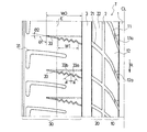
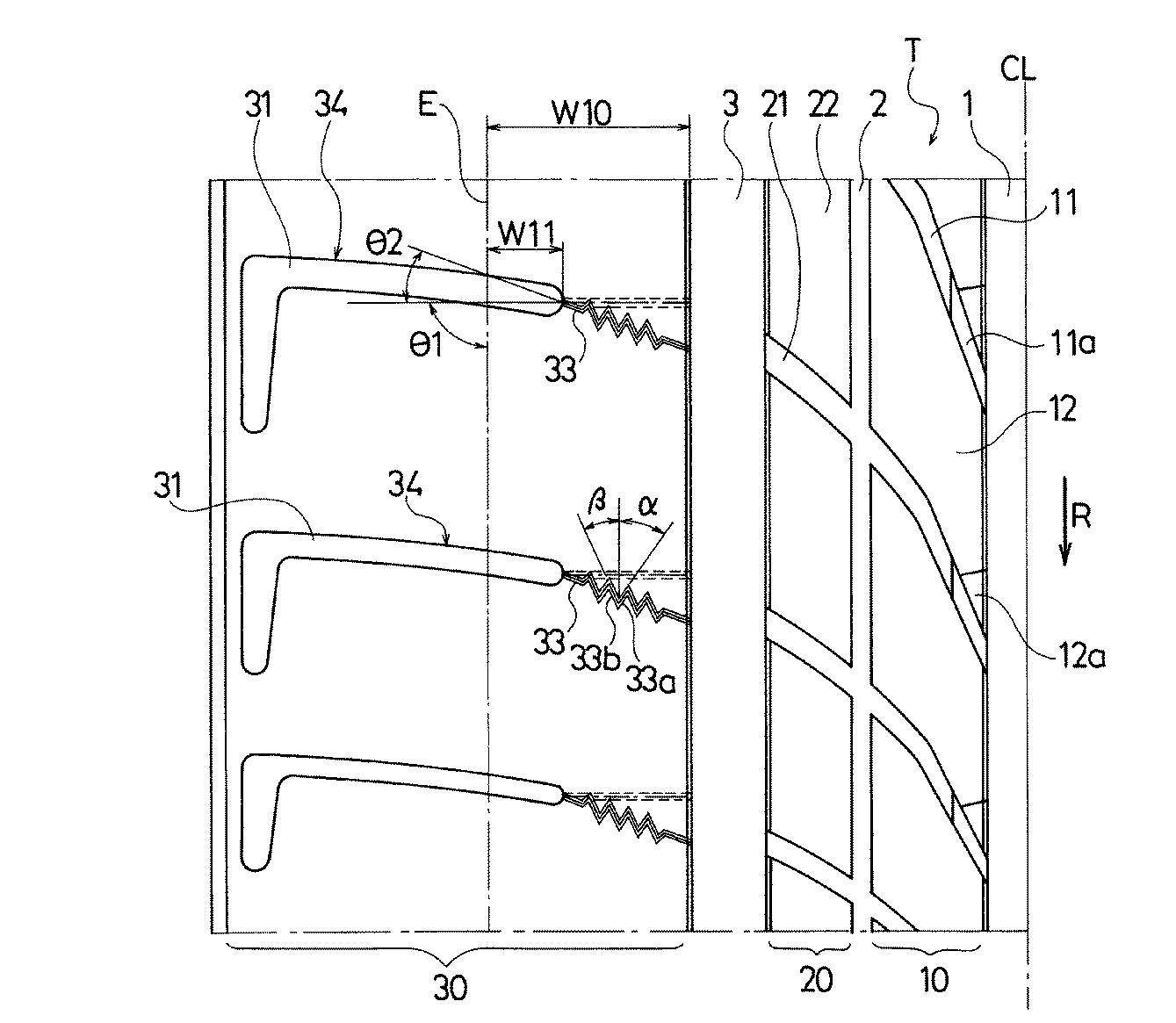
図5は本発明の他の実施形態からなる空気入りタイヤのトレッドパターンのタイヤ赤道線CLを境とする片側を示す展開図である。図6は図5のラグ溝とサイプとを連結してなる複合溝を示す拡大図である。なお、図1〜図4と同一物には同一符号を付してその部分の詳細な説明は省略する。 FIG. 5 is a developed view showing one side of the tire equator line CL of the tread pattern of the pneumatic tire according to another embodiment of the present invention. FIG. 6 is an enlarged view showing a composite groove formed by connecting the lug groove and the sipe shown in FIG. The same components as those in FIGS. 1 to 4 are denoted by the same reference numerals, and detailed description thereof is omitted.
図5において、ショルダー陸部30には、タイヤ幅方向に延びるラグ溝31とサイプ33とを連結してなる複数本の複合溝34が形成されている。これら複合溝34はサイプ側の端部が内側の周方向溝3に連通し、ラグ溝側の端部が接地端Eの外側まで延長している。サイプ33は、トレッド表面ではジグザグ状又は波状となる部分を含み底部では実質的に直線状に収束した3次元構造を有している(図6参照)。しかも、サイプ33のトレッド表面での延長方向と底部での延長方向は互いに交差する関係になっている。
In FIG. 5, the
上記空気入りタイヤでは、複合溝34のサイプ33をトレッド表面ではジグザグ状又は波状となる部分を含み底部では実質的に直線状に収束した3次元構造としているので、図7に示すように、タイヤが転動する際の踏み込み時と蹴り出し時において、トレッド部Tのタイヤ周方向の曲率変化に対して、サイプ33が底部を基点として開口してショルダー陸部30の微細な屈曲を許容するので、トレッドゴムのタイヤ周方向の引張り変形を抑制し、それによって転がり抵抗を低減することができる。特に、タイヤ転動時におけるトレッド部Tの曲率変化が最も大きいショルダー陸部30にラグ溝31とサイプ33とからなる複合溝34を配置することにより、転がり抵抗を効果的に低減することができる。
In the pneumatic tire, the
ショルダー陸部30にラグ溝とサイプとからなる複数本の複合溝を付加した場合、それに伴って横方向の入力を支える能力が低下する恐れがあるが、サイプ33はトレッド表面ではジグザグ状又は波状となる部分を含み、かつサイプ33のトレッド表面での延長方向と底部での延長方向とが互いに交差する関係にあるので、横方向の入力に対してショルダー陸部30の倒れ込みを抑制し、操縦安定性を十分に確保することができる。
When a plurality of composite grooves composed of lug grooves and sipes are added to the
ショルダー陸部30の接地領域内でのタイヤ幅方向の長さW10に対してラグ溝31の接地領域内でのタイヤ幅方向の長さW11はW11/W10=0.40〜0.80の関係になっている。これにより、操縦安定性を確保し、かつ排水性を確保することができる。W11/W10が0.40未満であると接地領域内でラグ溝31が占める割合が少ないため排水性が低下し、逆に0.80を超えると横方向の入力を支える能力が低下するため操縦安定性が低下する。
The length W11 in the tire width direction in the contact region of the
複合溝34を構成するサイプ33の深さは、それに繋がるラグ溝31の最大深さの80%〜100%の範囲に設定されている。これにより、転がり抵抗の低減効果を最大限に発揮することが可能になる。サイプ33の深さがラグ溝31の最大深さの80%未満であるとタイヤ転動時のサイプ33の開口が不十分になるため転がり抵抗の低減効果が不十分になり、場合によっては、サイプ底でのクラック発生要因となり、逆に100%を超えてもそれ以上の効果が見込めない。
The depth of the
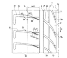
3次元構造を有するサイプとラグ溝とからなる複合溝は、ショルダー陸部以外の陸部に設けることも可能である。図8は図5の変形例を示す展開図である。図8において、中間陸部20には、タイヤ幅方向に延びるラグ溝21とサイプ23とを連結してなる複数本の複合溝24が形成されている。これら複合溝24は、一端が外側の周方向溝3に連通し、他端が内側の周方向溝2に連通している。複合溝24を構成するサイプ23は、トレッド表面ではジグザグ状又は波状となる部分を含み底部では実質的に直線状に収束した3次元構造を有している。しかも、サイプ23のトレッド表面での延長方向と底部での延長方向は互いに交差する関係になっている。
The composite groove composed of a sipe and a lug groove having a three-dimensional structure can be provided in a land portion other than the shoulder land portion. FIG. 8 is a development view showing a modification of FIG. In FIG. 8, the
このようにショルダー陸部30の内側に位置する中間陸部20にも3次元構造を有するサイプ23とラグ溝21とからなる複合溝24を設けることにより、ショルダー陸部30の変形を促進し、転がり抵抗の低減効果を高めることができる。サイプ23の寸法及び角度は、前述のサイプ33に準じて設定すれば良い。
In this way, the
タイヤサイズが195/65R15であり、トレッド部にタイヤ周方向に延びる複数本の周方向溝を設け、これら周方向溝により複数列の陸部を区画した空気入りタイヤにおいて、図1に示すように、ショルダー陸部にタイヤ幅方向に延びる複数本のサイプを設け、これらサイプをトレッド表面ではジグザグ状となる部分を含み底部では実質的に直線状に収束した3次元構造とし、かつ、サイプのトレッド表面での延長方向と底部での延長方向とを互いに交差する関係にすると共に、サイプの底部での延長方向の角度θ1、サイプのトレッド表面での延長方向の角度θ2、サイプの第1分節の角度α、サイプの第2分節の角度β、サイプのトレッド表面でのタイヤ幅方向の長さW0、サイプのトレッド表面でのジグザグ状となる部分のタイヤ幅方向の長さW1を表1のように設定した実施例1,2のタイヤを作製した。 In a pneumatic tire having a tire size of 195 / 65R15, provided with a plurality of circumferential grooves extending in the tire circumferential direction in the tread portion, and dividing a plurality of rows of land portions by these circumferential grooves, as shown in FIG. The shoulder land portion is provided with a plurality of sipes extending in the tire width direction, the sipe has a three-dimensional structure that includes a zigzag portion on the tread surface and converges substantially linearly at the bottom, and the sipe tread The extending direction at the surface and the extending direction at the bottom cross each other, and the angle θ1 of the extending direction at the bottom of the sipe, the angle θ2 of the extending direction at the tread surface of the sipe, and the first segment of the sipe The angle α, the angle β of the second segment of the sipe, the length W0 in the tire width direction on the tread surface of the sipe, and the tire width of the zigzag portion on the tread surface of the sipe The length W1 of the direction to produce the tires of Examples 1 and 2 were set as shown in Table 1.
比較のため、ショルダー陸部から上記3次元構造を有するサイプを削除したタイヤ(比較例1)と、ショルダー陸部に上記3次元構造を有するサイプの替わりに直線状のサイプを設けたタイヤ(比較例2)と、ショルダー陸部に上記3次元構造を有するサイプの替わりにジグザグ形状を有するサイプを設けたタイヤ(比較例3)を用意した。 For comparison, a tire in which the sipe having the three-dimensional structure is deleted from the shoulder land portion (Comparative Example 1) and a tire in which a straight sipe is provided in place of the sipe having the three-dimensional structure in the shoulder land portion (comparison) Example 2) and a tire (Comparative Example 3) provided with a sipe having a zigzag shape instead of a sipe having the above three-dimensional structure on the shoulder land portion were prepared.
これらタイヤについて、下記の評価方法により、転がり抵抗及び操縦安定性を評価し、その結果を表1に併せて示した。 These tires were evaluated for rolling resistance and steering stability by the following evaluation methods, and the results are also shown in Table 1.
転がり抵抗:
試験タイヤをリムサイズ15×6Jのホイールに組み付け、空気圧180kPa(JATMA標準空気圧)、負荷荷重4.5kN、ドラム回転速度80km/hの条件にて転がり抵抗を測定した。評価結果は、測定値の逆数を用い、比較例1を100とする指数にて示した。この指数値が大きいほど転がり抵抗が小さいことを意味する。
Rolling resistance:
The test tire was assembled on a wheel having a rim size of 15 × 6 J, and rolling resistance was measured under the conditions of an air pressure of 180 kPa (JATMA standard air pressure), a load of 4.5 kPa, and a drum rotation speed of 80 KM / h. The evaluation results are shown as an index using Comparative Example 1 as 100, using the reciprocal of the measured value. It means that rolling resistance is so small that this index value is large.
操縦安定性:
試験タイヤをリムサイズ15×6Jのホイールに組み付けて排気量2000ccのFR車両に装着し、空気圧180kPaとして、テストドライバーによる操縦安定性のフィーリング評価を行った。評価結果は、比較例1を100とする指数にて示した。この指数値が大きいほど操縦安定性が優れていることを意味する。
Steering stability:
The test tire was assembled on a wheel with a rim size of 15 × 6J and mounted on an FR vehicle with a displacement of 2000 cc. The air pressure was 180 kPa, and the driving stability of the test driver was evaluated. The evaluation results are shown as an index with Comparative Example 1 as 100. The larger the index value, the better the steering stability.
この表1から明らかなように、実施例1,2のタイヤは比較例1との対比において操縦安定性の低下を最小限に抑えながら転がり抵抗を低減することができた。一方、比較例2のタイヤは、転がり抵抗の低減効果が認められるものの、操縦安定性の低下が顕著であった。比較例3のタイヤは、転がり抵抗の低減効果が不十分であった。 As is clear from Table 1, the tires of Examples 1 and 2 were able to reduce rolling resistance while minimizing a decrease in steering stability in comparison with Comparative Example 1. On the other hand, in the tire of Comparative Example 2, although the rolling resistance reduction effect was recognized, the steering stability was significantly reduced. The tire of Comparative Example 3 was insufficient in reducing rolling resistance.
次に、タイヤサイズが195/65R15であり、トレッド部にタイヤ周方向に延びる複数本の周方向溝を設け、これら周方向溝により複数列の陸部を区画した空気入りタイヤにおいて、図5に示すように、ショルダー陸部にタイヤ幅方向に延びるラグ溝とサイプとを連結してなる複数本の複合溝を設け、サイプをトレッド表面ではジグザグ状となる部分を含み底部では実質的に直線状に収束した3次元構造とし、かつ、サイプのトレッド表面での延長方向と底部での延長方向とを互いに交差する関係にすると共に、サイプの底部での延長方向の角度θ1、サイプのトレッド表面での延長方向の角度θ2、サイプの第1分節の角度α、サイプの第2分節の角度β、ショルダー陸部の接地領域内でのタイヤ幅方向の長さW10、ラグ溝の接地領域内でのタイヤ幅方向の長さW11を表2のように設定した実施例11,12のタイヤを作製した。 Next, in the pneumatic tire in which the tire size is 195 / 65R15, a plurality of circumferential grooves extending in the tire circumferential direction are provided in the tread portion, and a plurality of rows of land portions are partitioned by the circumferential grooves, FIG. As shown in the figure, a plurality of compound grooves formed by connecting lug grooves and sipes extending in the tire width direction are provided on the shoulder land portion, and the sipes include a zigzag portion on the tread surface and are substantially linear at the bottom portion. The extension direction at the tread surface of the sipe and the extension direction at the bottom part intersect each other, and the angle θ1 of the extension direction at the bottom part of the sipe, The angle θ2 in the extending direction of the sipe, the angle α of the first segment of the sipe, the angle β of the second segment of the sipe, the length W10 in the tire width direction within the ground contact region of the shoulder land, and the ground contact region of the lug groove The tire width direction of the length W11 were produced tires of Examples 11 and 12 were set as shown in Table 2 in.
比較のため、ショルダー陸部から上記3次元構造を有するサイプを削除したタイヤ(比較例11)と、ショルダー陸部に上記3次元構造を有するサイプの替わりに直線状のサイプを設けたタイヤ(比較例12)と、ショルダー陸部に上記3次元構造を有するサイプの替わりにジグザグ形状を有するサイプを設けたタイヤ(比較例13)を用意した。 For comparison, a tire in which the sipe having the three-dimensional structure is deleted from the shoulder land portion (Comparative Example 11) and a tire in which a straight sipe is provided in place of the sipe having the three-dimensional structure in the shoulder land portion (comparison) Example 12) and a tire (Comparative Example 13) provided with a sipe having a zigzag shape instead of the sipe having the above three-dimensional structure on the shoulder land portion were prepared.
これらタイヤについて、上記と同様の評価方法により、転がり抵抗及び操縦安定性を評価し、その結果を表2に併せて示した。但し、評価結果の基準は比較例11とした。 These tires were evaluated for rolling resistance and steering stability by the same evaluation method as described above, and the results are also shown in Table 2. However, the reference of the evaluation result was set to Comparative Example 11.
この表2から明らかなように、実施例11,12のタイヤは比較例11との対比において操縦安定性の低下を最小限に抑えながら転がり抵抗を低減することができた。一方、比較例12のタイヤは、転がり抵抗の低減効果が認められるものの、操縦安定性の低下が顕著であった。比較例13のタイヤは、転がり抵抗の低減効果が不十分であった。 As is apparent from Table 2, the tires of Examples 11 and 12 were able to reduce rolling resistance while minimizing the decrease in steering stability in comparison with Comparative Example 11. On the other hand, in the tire of Comparative Example 12, although the rolling resistance reduction effect was recognized, the steering stability was significantly reduced. The tire of Comparative Example 13 was insufficient in reducing rolling resistance.
1,2,3 周方向溝
10,20,30 陸部
11,21,31 ラグ溝
12,22,ブロック
23,33 サイプ
24,34 複合溝
CL タイヤ赤道線
E 接地端
T トレッド部
1, 2, 3
Claims (16)
Priority Applications (1)
| Application Number | Priority Date | Filing Date | Title |
|---|---|---|---|
| JP2008208883A JP5223534B2 (en) | 2008-08-14 | 2008-08-14 | Pneumatic tire |
Applications Claiming Priority (1)
| Application Number | Priority Date | Filing Date | Title |
|---|---|---|---|
| JP2008208883A JP5223534B2 (en) | 2008-08-14 | 2008-08-14 | Pneumatic tire |
Publications (2)
| Publication Number | Publication Date |
|---|---|
| JP2010042765A true JP2010042765A (en) | 2010-02-25 |
| JP5223534B2 JP5223534B2 (en) | 2013-06-26 |
Family
ID=42014511
Family Applications (1)
| Application Number | Title | Priority Date | Filing Date |
|---|---|---|---|
| JP2008208883A Active JP5223534B2 (en) | 2008-08-14 | 2008-08-14 | Pneumatic tire |
Country Status (1)
| Country | Link |
|---|---|
| JP (1) | JP5223534B2 (en) |
Cited By (3)
| Publication number | Priority date | Publication date | Assignee | Title |
|---|---|---|---|---|
| JP2013129325A (en) * | 2011-12-21 | 2013-07-04 | Bridgestone Corp | Pneumatic tire |
| WO2016056597A1 (en) * | 2014-10-07 | 2016-04-14 | 横浜ゴム株式会社 | Pneumatic tire |
| CN111699096A (en) * | 2018-02-14 | 2020-09-22 | 横滨橡胶株式会社 | Pneumatic tire |
Citations (10)
| Publication number | Priority date | Publication date | Assignee | Title |
|---|---|---|---|---|
| JPS59199306A (en) * | 1983-04-12 | 1984-11-12 | ミシユラン、エ、コンパニ−(コンパニ−、ゼネラ−ル、デ、ゼタブリスマン、ミシユラン) | Tire tread |
| JPH03167008A (en) * | 1989-11-27 | 1991-07-18 | Yokohama Rubber Co Ltd:The | Pneumatic tire |
| JPH0789303A (en) * | 1993-08-30 | 1995-04-04 | Goodyear Tire & Rubber Co:The | Pneumatic tire |
| JPH0994829A (en) * | 1995-09-28 | 1997-04-08 | Bridgestone Corp | Vulcanization molding mold and pneumatic tire produced using the same |
| JPH1024709A (en) * | 1996-07-11 | 1998-01-27 | Sumitomo Rubber Ind Ltd | Pneumatic tire |
| JPH11240314A (en) * | 1997-12-24 | 1999-09-07 | Bridgestone Corp | Pneumatic tire |
| JP2003118322A (en) * | 2001-10-17 | 2003-04-23 | Toyo Tire & Rubber Co Ltd | Pneumatic tire |
| JP2003320814A (en) * | 2002-04-30 | 2003-11-11 | Yokohama Rubber Co Ltd:The | Pneumatic tire |
| JP2006298055A (en) * | 2005-04-18 | 2006-11-02 | Bridgestone Corp | Pneumatic tire |
| WO2007004369A1 (en) * | 2005-06-30 | 2007-01-11 | Bridgestone Corporation | Pneumatic tire |
-
2008
- 2008-08-14 JP JP2008208883A patent/JP5223534B2/en active Active
Patent Citations (10)
| Publication number | Priority date | Publication date | Assignee | Title |
|---|---|---|---|---|
| JPS59199306A (en) * | 1983-04-12 | 1984-11-12 | ミシユラン、エ、コンパニ−(コンパニ−、ゼネラ−ル、デ、ゼタブリスマン、ミシユラン) | Tire tread |
| JPH03167008A (en) * | 1989-11-27 | 1991-07-18 | Yokohama Rubber Co Ltd:The | Pneumatic tire |
| JPH0789303A (en) * | 1993-08-30 | 1995-04-04 | Goodyear Tire & Rubber Co:The | Pneumatic tire |
| JPH0994829A (en) * | 1995-09-28 | 1997-04-08 | Bridgestone Corp | Vulcanization molding mold and pneumatic tire produced using the same |
| JPH1024709A (en) * | 1996-07-11 | 1998-01-27 | Sumitomo Rubber Ind Ltd | Pneumatic tire |
| JPH11240314A (en) * | 1997-12-24 | 1999-09-07 | Bridgestone Corp | Pneumatic tire |
| JP2003118322A (en) * | 2001-10-17 | 2003-04-23 | Toyo Tire & Rubber Co Ltd | Pneumatic tire |
| JP2003320814A (en) * | 2002-04-30 | 2003-11-11 | Yokohama Rubber Co Ltd:The | Pneumatic tire |
| JP2006298055A (en) * | 2005-04-18 | 2006-11-02 | Bridgestone Corp | Pneumatic tire |
| WO2007004369A1 (en) * | 2005-06-30 | 2007-01-11 | Bridgestone Corporation | Pneumatic tire |
Cited By (5)
| Publication number | Priority date | Publication date | Assignee | Title |
|---|---|---|---|---|
| JP2013129325A (en) * | 2011-12-21 | 2013-07-04 | Bridgestone Corp | Pneumatic tire |
| WO2016056597A1 (en) * | 2014-10-07 | 2016-04-14 | 横浜ゴム株式会社 | Pneumatic tire |
| US10603961B2 (en) | 2014-10-07 | 2020-03-31 | The Yokohama Rubber Co., Ltd. | Pneumatic tire |
| CN111699096A (en) * | 2018-02-14 | 2020-09-22 | 横滨橡胶株式会社 | Pneumatic tire |
| CN111699096B (en) * | 2018-02-14 | 2022-08-16 | 横滨橡胶株式会社 | Pneumatic tire |
Also Published As
| Publication number | Publication date |
|---|---|
| JP5223534B2 (en) | 2013-06-26 |
Similar Documents
| Publication | Publication Date | Title |
|---|---|---|
| JP6393208B2 (en) | Pneumatic tire | |
| JP4881697B2 (en) | Pneumatic tire | |
| US9994077B2 (en) | Pneumatic tire | |
| JP6790663B2 (en) | tire | |
| JP4685922B2 (en) | Pneumatic tire | |
| JP4873988B2 (en) | Pneumatic tire | |
| CN107031307B (en) | Pneumatic tire | |
| JP6776620B2 (en) | tire | |
| JP2010247759A (en) | Pneumatic tire | |
| JP2005170147A (en) | Pneumatic tire | |
| JP2010241267A (en) | Pneumatic tire | |
| CN107639975B (en) | Tyre for vehicle wheels | |
| JP2010260471A (en) | Pneumatic tire | |
| JP4367667B1 (en) | Pneumatic tire | |
| JP2007230251A (en) | Pneumatic tire | |
| JP6575649B2 (en) | Pneumatic tire | |
| JP5200123B2 (en) | Heavy duty pneumatic tire | |
| JP5223534B2 (en) | Pneumatic tire | |
| US10000092B2 (en) | Pneumatic tire | |
| JP2008030656A (en) | Pneumatic tire | |
| CN110936770B (en) | Tyre | |
| JP6416024B2 (en) | Pneumatic tire | |
| RU2506170C1 (en) | Pneumatic tire | |
| JP4648113B2 (en) | Pneumatic tire | |
| JP4285617B2 (en) | Pneumatic radial tire |
Legal Events
| Date | Code | Title | Description |
|---|---|---|---|
| A621 | Written request for application examination |
Free format text: JAPANESE INTERMEDIATE CODE: A621 Effective date: 20110809 |
|
| A977 | Report on retrieval |
Free format text: JAPANESE INTERMEDIATE CODE: A971007 Effective date: 20121001 |
|
| TRDD | Decision of grant or rejection written | ||
| A01 | Written decision to grant a patent or to grant a registration (utility model) |
Free format text: JAPANESE INTERMEDIATE CODE: A01 Effective date: 20130212 |
|
| A61 | First payment of annual fees (during grant procedure) |
Free format text: JAPANESE INTERMEDIATE CODE: A61 Effective date: 20130225 |
|
| R150 | Certificate of patent or registration of utility model |
Free format text: JAPANESE INTERMEDIATE CODE: R150 Ref document number: 5223534 Country of ref document: JP Free format text: JAPANESE INTERMEDIATE CODE: R150 |
|
| FPAY | Renewal fee payment (event date is renewal date of database) |
Free format text: PAYMENT UNTIL: 20160322 Year of fee payment: 3 |
|
| R250 | Receipt of annual fees |
Free format text: JAPANESE INTERMEDIATE CODE: R250 |
|
| R250 | Receipt of annual fees |
Free format text: JAPANESE INTERMEDIATE CODE: R250 |
|
| R250 | Receipt of annual fees |
Free format text: JAPANESE INTERMEDIATE CODE: R250 |
|
| R250 | Receipt of annual fees |
Free format text: JAPANESE INTERMEDIATE CODE: R250 |
|
| R250 | Receipt of annual fees |
Free format text: JAPANESE INTERMEDIATE CODE: R250 |
|
| R250 | Receipt of annual fees |
Free format text: JAPANESE INTERMEDIATE CODE: R250 |
|
| R250 | Receipt of annual fees |
Free format text: JAPANESE INTERMEDIATE CODE: R250 |
|
| R250 | Receipt of annual fees |
Free format text: JAPANESE INTERMEDIATE CODE: R250 |
|
| S531 | Written request for registration of change of domicile |
Free format text: JAPANESE INTERMEDIATE CODE: R313531 |
|
| R350 | Written notification of registration of transfer |
Free format text: JAPANESE INTERMEDIATE CODE: R350 |
|
| R250 | Receipt of annual fees |
Free format text: JAPANESE INTERMEDIATE CODE: R250 |