JP2010042191A - Showcase - Google Patents
Showcase Download PDFInfo
- Publication number
- JP2010042191A JP2010042191A JP2008209681A JP2008209681A JP2010042191A JP 2010042191 A JP2010042191 A JP 2010042191A JP 2008209681 A JP2008209681 A JP 2008209681A JP 2008209681 A JP2008209681 A JP 2008209681A JP 2010042191 A JP2010042191 A JP 2010042191A
- Authority
- JP
- Japan
- Prior art keywords
- shelf
- led
- led element
- showcase
- illumination
- Prior art date
- Legal status (The legal status is an assumption and is not a legal conclusion. Google has not performed a legal analysis and makes no representation as to the accuracy of the status listed.)
- Granted
Links
Images


Landscapes
- Arrangement Of Elements, Cooling, Sealing, Or The Like Of Lighting Devices (AREA)
- Freezers Or Refrigerated Showcases (AREA)
- Fastening Of Light Sources Or Lamp Holders (AREA)
Abstract
Description
本発明は、本体内に陳列室を構成し、該陳列室内に複数段の棚を架設して商品を陳列して成るショーケースであって、特に、棚の下方に陳列された商品の照明に関するものである。 The present invention relates to a showcase in which a display room is configured in a main body, and a plurality of shelves are installed in the display room to display products, and more particularly to lighting of products displayed below the shelves. Is.
従来よりこの種ショーケースは、例えば前面に開口を有する低温ショーケースがある(例えば特許文献1参照)。係る低温ショーケースは、断面略コ字状の断熱壁の開口上縁に形成される吐出口から、開口下縁の吸込口に向けて冷気を吐出し、断熱壁にて囲繞された陳列室内は所定の温度に冷却される。そして、開口上縁の外側に位置するキャノピーや開口両側縁及び陳列室内に複数段架設される棚の前部下面などに複数の蛍光灯を取り付け陳列室内及びショーケース自体の照明を行っていた。
一般に、陳列室内を所定の冷却温度に冷却して成る低温ショーケースでは、缶やペットボトルなどに充填された飲料などを陳列する場合には、棚は後方から前方に向けて低く傾斜するように陳列室内に架設されている。そのため、当該飲料などの商品は自重によって手前側に移動することとなる。 Generally, in a low-temperature showcase in which the display room is cooled to a predetermined cooling temperature, when displaying beverages filled in cans or PET bottles, the shelf is inclined downward from the rear to the front. It is built in the display room. Therefore, goods, such as the said drink, will move to the near side by dead weight.
従って、上述したように、棚の前部下面に設けられる蛍光灯などの照明装置によって、当該棚の下側に架設される棚前部に陳列される商品は効果的に照明される。 Therefore, as described above, the products displayed on the front part of the shelf installed under the shelf are effectively illuminated by the illumination device such as a fluorescent lamp provided on the lower surface of the front part of the shelf.
しかしながら、照明装置として用いられる蛍光灯は、電気エネルギーを可視放射、赤外放射、紫外放射に変換し、可視光線を放射することで、照明として用いるものである。その際、熱損失が生じるため、蛍光灯自体のみ成らず、当該蛍光灯による輻射熱によって、陳列室内が加熱される問題がある。また、蛍光灯は、交流を使用するためチラツキが生じる問題があるため、目に悪影響を及ぼす問題がある。更に、蛍光灯は、経年劣化による輝度の低下や点灯不良により、交換作業が余儀なくされる。そのため、蛍光灯の交換作業を強いられることとなり、作業が煩雑となる問題がある。 However, a fluorescent lamp used as an illumination device is used as illumination by converting electric energy into visible radiation, infrared radiation, and ultraviolet radiation and emitting visible light. At this time, heat loss occurs, so that there is a problem that not only the fluorescent lamp itself but also the display room is heated by the radiant heat from the fluorescent lamp. In addition, the fluorescent lamp has a problem of causing flickering due to the use of alternating current, and thus has a problem of adversely affecting the eyes. Furthermore, the fluorescent lamp is forced to be replaced due to a decrease in luminance or lighting failure due to aging. For this reason, there is a problem that the fluorescent lamp replacement work is forced and the work becomes complicated.
そこで、これら蛍光灯による不都合を解消すべく、昨今では、LED素子を有するLED照明装置が照明装置として採用されている。しかし、LED素子からの照射光は、指向性が強いため、棚の前部下面に設けられたLED照明装置では、主として当該棚の前部下方に照射光が照射されることとなるため、蛍光灯の場合に比べて、下側に設けられる棚の奥方への照明が著しく不足するという問題がある。 Therefore, in recent years, an LED lighting device having an LED element has been adopted as a lighting device in order to eliminate the disadvantages caused by these fluorescent lamps. However, since the irradiation light from the LED element has strong directivity, in the LED lighting device provided on the front lower surface of the shelf, the irradiation light is mainly irradiated below the front of the shelf. Compared to the case of a lamp, there is a problem that the illumination to the back of the shelf provided on the lower side is remarkably insufficient.
例えば、発泡スチロールなどにより形成されるトレーに収容された商品などや、棚が略水平状態で架設されている場合には、商品が手前側から取り出されても、奥側に位置する商品は、手前側に自重によって移動しない。そのため、上側に位置する棚の前部下面に設けられる照明装置は、商品が置かれていない棚前部を主として照明するため、実際に商品が陳列されている奥側の商品を効果的に照明することができないこととなる。 For example, if the product is contained in a tray formed of foamed polystyrene or the like, or if the shelf is installed in a substantially horizontal state, the product located on the back side will be Do not move to the side by its own weight. For this reason, the lighting device provided on the lower surface of the front part of the shelf located on the upper side mainly illuminates the front part of the shelf on which no product is placed, and thus effectively illuminates the rear product on which the product is actually displayed. It will not be possible.
そのため、係る状況では、商品を管理する店員が、陳列室内に陳列されている商品の状況を監視し、手前側の商品が無くなったら、逐次奥側の商品を前側に置き換える前出し作業を行う必要があった。 Therefore, in such a situation, the store clerk who manages the product needs to monitor the status of the product displayed in the display room, and when the product on the front side is gone, it is necessary to perform the advance work of sequentially replacing the product on the back side with the front side was there.
本発明は、従来の技術的課題を解決するために成されたものであり、陳列室内に陳列される商品の陳列状況に応じて容易に、且つ、効果的に照明することを可能とするショーケースを提供する。 The present invention has been made in order to solve the conventional technical problems, and can be easily and effectively illuminated according to the display state of the goods displayed in the display room. Provide a case.
本発明のショーケースは、陳列室内に架設した複数段の棚上に商品を陳列するものであって、棚の下面に設けられ、当該棚の下方に陳列された商品を照明するLED素子を有するLED照明装置を備え、このLED照明装置は、LED素子からの光の照射角度を、陳列室の奥行き方向において変更可能とされていることを特徴とする。 The showcase of the present invention displays products on a plurality of shelves installed in a display room, and has LED elements that are provided on the lower surface of the shelf and illuminate the products displayed below the shelves. An LED illumination device is provided, and this LED illumination device is characterized in that the irradiation angle of light from the LED element can be changed in the depth direction of the display room.
請求項2の発明のショーケースは、上記発明において、LED照明装置は、LED素子を棚の下面に取り付けるためのLED取付部材を有し、このLED取付部材は、棚に対して回動自在に取り付けられていることを特徴とする。
The showcase of the invention of
請求項3の発明のショーケースは、上記発明において、LED取付部材は、自重で回動自在とされていることを特徴とする。 According to a third aspect of the present invention, in the above invention, the LED mounting member is rotatable by its own weight.
請求項4の発明のショーケースは、上記各発明において、LED照明装置は、LED素子を棚の下面に取り付けるためのLED取付部材を有し、このLED取付部材は、陳列室の奥行き方向において移動自在とされていることを特徴とする。 According to a fourth aspect of the present invention, in the above inventions, the LED lighting device includes an LED mounting member for mounting the LED element on the lower surface of the shelf, and the LED mounting member moves in the depth direction of the display room. It is characterized by being free.
本発明によれば、陳列室内に架設した複数段の棚上に商品を陳列するショーケースにおいて、棚の下面に設けられ、当該棚の下方に陳列された商品を照明するLED素子を有するLED照明装置を備え、このLED照明装置は、LED素子からの光の照射角度を、陳列室の奥行き方向において変更可能とされているので、LED素子からの光の照射角度を棚の前部から奥行き方向に渡って任意に変更することが可能となる。 According to the present invention, in a showcase that displays products on a plurality of shelves installed in a display room, the LED illumination is provided on the lower surface of the shelf and has LED elements that illuminate the products displayed below the shelves. This LED illumination device is capable of changing the irradiation angle of light from the LED element in the depth direction of the display room, so that the irradiation angle of light from the LED element can be changed in the depth direction from the front of the shelf. It becomes possible to change arbitrarily over.
そのため、陳列室内の当該棚の下方に陳列される商品の陳列状況に応じて、例えば、陳列室手前側の商品が取り出され、奥方にのみ商品が陳列されている場合には、指向性が高いLED素子からの光の照射角度を奥行き方向に変更することで、商品を並べ替えることなく、効果的に照明することが可能となる。 Therefore, depending on the display status of the product displayed below the shelf in the display room, for example, when the product on the front side of the display room is taken out and the product is displayed only in the back, the directivity is high By changing the irradiation angle of the light from the LED element in the depth direction, it is possible to effectively illuminate the products without rearranging the products.
特に、任意にLED素子からの光の照射角度を奥行き方向において変更できるため、複数の照明パターンを実現でき、陳列効果の向上を図ることが可能となる。 In particular, since the irradiation angle of light from the LED element can be arbitrarily changed in the depth direction, a plurality of illumination patterns can be realized, and the display effect can be improved.
請求項2の発明によれば、上記発明において、LED照明装置は、LED素子を棚の下面に取り付けるためのLED取付部材を有し、このLED取付部材は、棚に対して回動自在に取り付けられているので、棚の下面に取り付けられるLED取付部材を回動操作することによって、容易にLED素子からの光の照射角度を奥行き方向で変更することができるようになる。
According to the invention of
請求項3の発明によれば、上記発明において、LED取付部材は、自重で回動自在とされているので、当該LED取付部材が設けられる棚が角度変更自在に取り付けられた場合であっても、その自重により回動し、常に、重心が真下を向くことで、棚下面に設けられるLED取付部材の直ぐ下方を照明することが可能となる。 According to the invention of claim 3, in the above invention, since the LED mounting member is rotatable by its own weight, even if the shelf on which the LED mounting member is provided is mounted so that the angle can be changed freely. It is possible to illuminate the portion immediately below the LED mounting member provided on the bottom surface of the shelf by rotating by its own weight and always having the center of gravity directly below.
これにより、棚の架設角度が変更された場合であっても、格別にLED照明装置の取付角度の調整作業を行うことなく、棚の下方に位置する陳列室内を効果的に照明することが可能となる。 As a result, even if the shelf installation angle is changed, it is possible to effectively illuminate the display room located below the shelf without specially adjusting the mounting angle of the LED lighting device. It becomes.
請求項4の発明によれば、上記各発明において、LED照明装置は、LED素子を棚の下面に取り付けるためのLED取付部材を有し、このLED取付部材は、陳列室の奥行き方向において移動自在とされているので、LED素子が設けられるLED取付部材の奥行き方向の取付位置を任意に、且つ、容易に変更することが可能となる。
According to the invention of
従って、棚下方に位置する陳列室内の商品の陳列状況に応じてLED素子の取付位置を調整でき、より効果的に商品の照明を実現することが可能となる。 Therefore, the mounting position of the LED element can be adjusted according to the display state of the product in the display room located below the shelf, and the product can be illuminated more effectively.
次に、図面を参照して本発明の実施形態について詳述する。図1は本発明を適用したショーケース1の斜視図、図2は図1のショーケース1の縦断側面図をそれぞれ示している。ショーケース1は、例えばスーパーマーケットなどの店舗内に据え付けられる縦型のオープンショーケースであり、前面に開口する断面略コ字状の断熱壁2と、据え付け現場において断熱壁2の側面に取り付けられた断熱性の側板5、5とから構成されている。
Next, embodiments of the present invention will be described in detail with reference to the drawings. FIG. 1 is a perspective view of a
ショーケース1の断熱壁2の内側にはそれぞれ間隔を存して仕切板4及び図示しないもう一枚の仕切板が取り付けられ、これら仕切板4などと断熱壁2との間に図示しない内外二層のダクトが形成されている。内側の仕切板4を構成する背部仕切板4Aの下端前方には、底板9が断熱壁2の底壁2Aとの間にダクト用の間隔を存して取り付けられており、これら仕切板4及び底板9の内側を陳列室11としている。
A
また、この陳列室11内には、高さ及び取付角度が変更可能であると共に、陳列室11内には棚30が複数段(本実施例では4段)架設されている。この棚30は、背部の図示しない支柱に取り付けられる一対のブラケット31及び当該ブラケット31、31間に架設される棚板32とから構成される。棚板32の前縁には、硬質合成樹脂により成形されるプライスレール34が取り付けられており、当該プライスレール34は、棚板32の装飾体を兼用している。また、この棚板32の前壁とプライスレール34との間には、所定の間隔が形成されており、当該間隔には棚板32上の商品が落下することを防止するためのガード35が取り付けられる。
In the
断熱壁2の前面開口12の上縁にはハニカム材13、14がそれぞれ取り付けられた内層吐出口16及び外層吐出口17が並設されており、これら内層吐出口16及び外層吐出口17は、前記内層ダクト及び外層ダクトにそれぞれ連通している。また、開口12の下縁には、内層吸込口18と外層吸込口19が並設されている。
An inner
一方、底板9下方後部には断熱壁2の底壁2A上に前記内層ダクト及び外層ダクトのそれぞれに対応する図示しない送風機が複数台設置されている。
On the other hand, a plurality of blowers (not shown) corresponding to the inner layer duct and the outer layer duct are installed on the
背部仕切板4A後方の内層ダクト内には冷却装置の冷却器39が縦設されており、前記内層ダクトに対応した送風機が運転されると冷却器と熱交換した冷気は内層ダクト内を上昇せられ、内層吐出口16より内層吸込口18に向かって吐出される。そして、内層吸込口18から吸い込まれた冷気は再び前記送風機によって加速される。
A
他方、前記外層ダクトに対応した送風機が運転されると外層ダクト内の空気は外層ダクト内を上昇せられ、外層吐出口17より外層吸込口19に向かって吐出される。そして、外層吸込口19から吸い込まれた空気は再び前記送風機によって加速される。これによって、開口12には前後二重のエアーカーテンが形成され、内側の冷気エアーカーテンの一部が陳列室11内に循環されて当該陳列室11は冷却される。
On the other hand, when the blower corresponding to the outer layer duct is operated, the air in the outer layer duct is raised in the outer layer duct and discharged from the outer
次に、図3の図2の部分拡大断面図を参照して、断熱壁2の天壁2B前部の構成について説明する。断熱壁2の天壁2B前端(上部前端)には、前方に張り出したキャノピー33が取り付けられており、このキャノピー33の内側には、陳列室11の前面開口12より外側に延在した状態で反射板45が取り付けられる。
Next, the configuration of the front portion of the
この反射板45は、化粧塗装が施された金属板にて構成されており、前部には、長手方向に渡って凹陥された照明取付部41が形成されている。この照明取付部41は、下後方に位置する陳列室11の前面開口12に向けて開口している。
The
そして、この照明取付部41の当該開口に対向する面は、照明取付面41Aとされており、上前方から陳列室11の前面開口12を臨む角度、即ち、後斜め下方の陳列室11方向に面して構成されており、当該照明取付面41Aには、LED照明装置38が取り付けられている。
The surface of the
このLED照明装置38は、長手方向に延在する基板42に所定間隔を存して複数のLED素子40により構成されている。基板42は、照明取付面41Aに当接した状態で、複数の固定ネジにより固定されている。なお、本実施例において用いられるLED素子40は、日亜化学製のチップタイプの白色のLED照明(品番NS6W083T)である。また、当該LED素子40は、一列若しくは、前後に二列以上並設してもよい。そして、照明取付部41の照明取付面41Aは、LED素子40・・、基板42を下側から囲繞するかたちで取り付けられる透光性のシェード46によってカバーされる。
The
係る構成により、LED照明装置38が点灯されると、シェード46において拡散された後のLED素子40の照射光により、陳列室11の外側に位置する上前方から効果的に陳列室11内全体を照明することが可能となる。
With this configuration, when the
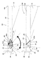
次に、図4及び図5を参照して棚30に設けられるLED照明装置20について説明する。図4は棚30(略水平架設)に取り付けられたLED照明装置20による照明範囲を示すショーケース1の部分概略断面図、図5は図4の部分拡大図をそれぞれ示している。
Next, the
まずはじめに、各棚30が陳列室11内に略水平に架設されている場合について説明する。各棚30を構成する棚板32の下面前部には、棚板32の長手方向(本実施例では左右方向)に渡って、LED照明装置20が設けられている。尚、本実施例では、棚板32が下面に開口する矩形状にて構成されているため、当該LED照明装置20は、棚板32の商品載置面の下面に取り付けられ、これにより、当該LED照明装置20は、棚板32内に収容された状態とされる。従って、図2にはLED照明装置20は表れない。
First, the case where each
図5において、下側の棚30ではLED照明装置20の断面図を示しており、上側の棚30ではLED照明装置20によるLED素子21からの光の照射角度が変更可能であることを示している。LED照明装置20は、取り付けられた棚30の下方の棚30上や底板9上を照明するものである。LED照明装置20は、棚取付部23、LED素子取付部24及び反射部25とを有するLED取付部材22と、複数のLED素子21・・・が所定間隔を存して複数設けられる基板26とから構成される。尚、当該LED素子21は、上記LED素子40と同様の構成であるため、説明を省略する。
In FIG. 5, the
LED取付部材22を構成する棚取付部23は、棚30(本実施例では棚板32)下面にネジ止めなどにより固定されるものである。そして、LED素子取付部24と反射部25は、それぞれ棚30の長手方向(左右方向)に延在して構成される板状部材であり、LED素子取付部24の後端と、反射部25の前端は、所定角度(例えば略90°)を成した状態で固定される。尚、LED素子取付部24と反射部25とは、一枚の板状部材を折曲形成することにより一体に構成したものであってもよい。そして、これらの中心角部分には、枢支部材22Aにより、棚取付部23の前縁部に所定の抵抗をもって回動自在に取り付けられる。
The
そして、手前側に位置するLED素子取付部24の後面(反射部25側の面)には、長手方向(左右方向)に渡って上述した如きLED素子21を備えた基板26が設けられる。奥側に位置する反射部25の前面(LED素子取付部24側の面)には、光を反射する反射板25Aが設けられる。更に、これらLED素子取付部24の下端と反射部25の下端との間には、透光性を有するシェード27が取り付けられる。
And the board |
係る構成により、指向性の高いLED素子21からの照射光は、シェード27を介して、棚30の下方に向けて照射される。尚、図4や図5の下側の棚30に示されるLED照明装置20は、シェード27の面と棚板32の下端(下面開口)とが略面一となる角度に調整したものであり、係る状態で、LED素子21からの照射光及び対向して設けられる反射板25Aにより反射された反射光は、下側の棚30に陳列された商品、特に、棚30の前側に陳列された商品を照明する。
With such a configuration, the irradiation light from the
当該LED素子取付部24及び反射部25を枢支部材22Aの軸を中心としてその抵抗に逆らって陳列室11の奥行き方向に回動させることで、LED素子21からの光の照射角度は奥行き方向に変更することができる。即ち、図5の上側の棚30に設けられるLED照明装置20において示されているように、LED素子取付部24(及び角度が固定されて設けられる反射部25)を枢支部材22Aの軸を中心として前側に回動させることで、LED素子21をより下向きとすることができ、その照射範囲(照射角度)を下側に位置する棚30の前部やその前方とすることができる。
By rotating the LED
そして、LED素子取付部24を枢支部材22Aの軸を中心としてその抵抗に逆らって後側に回動させることで、LED素子21をより背部仕切板4A側に向けることができ、その照射範囲(照射角度)を下側に位置する棚30の後部や背部仕切板4A方向とすることができる。尚、本実施例では、枢支部材22Aは、その回動機構に所定の抵抗を有しているため、角度調整後は、手を離してもその角度を維持することができる。
The
そのため、陳列室11内のLED照明装置20が取り付けられた棚30の下方に陳列される商品の陳列状況に応じて、例えば、陳列室11手前側の商品が取り出され、奥方にのみ商品が陳列されている場合には、指向性が高いLED素子21からの光の照射角度を奥行き方向に変更(調整)することで、商品を並べ替えることなく、効果的に照明することが可能となる。
Therefore, according to the display state of the goods displayed under the
また、棚30の手前側に商品を陳列し直した場合には、当該LED取付部材22を前側に回動させることで、LED素子21の光の照射角度を手前方向に変更(調整)する。これにより、商品の陳列状況に応じた適切な商品照明を実現することが可能となる。
Further, when the commodity is displayed again on the front side of the
なお、このとき、上述したようにLED取付部材22に設けられるシェード27の下面は、棚板32の下端(下面開口)と略面一となるように角度を調整した状態では、LED素子21からの照射光及び対向して設けられる反射板25Aにより反射された反射光は、下側の棚30に陳列された商品、特に、棚30の前側に陳列された商品を照明するように設けられている。そのため、手探りにてLED照明装置20のLED素子21からの照射光を下側の棚30の前側に陳列された商品を照明するように調整することが可能となり、作業性の向上を図ることができる。
At this time, in the state where the angle is adjusted so that the lower surface of the
このように、任意にLED素子21からの光の照射角度を奥行き方向において変更できるため、複数の照明パターンを実現でき、陳列効果の向上を図ることができる。
Thus, since the irradiation angle of the light from the
特に、枢支部材22Aを中心として手前方向や奥行き方向に回動操作することによって、容易にLED素子21からの光の照射角度を変更することができ、利便性の向上を図ることができる。
In particular, the rotation angle of the light from the
尚、図6は上記実施例におけるLED照明装置28を下面に開口を有していない棚板32Aに取り付けた場合について示している。この場合、上記実施例におけるLED取付部材22の棚取付部23を有していないものであり、上記LED素子取付部24及び反射部25により構成されるLED取付部材29は、棚板32Aの両側部であって棚板32A前部下面に設けられる保持部材47、47により所定の抵抗を持って、LED素子取付部24の後端と反射部25の前端とにより構成される中心角部分を中心として回動自在に取り付けられる。
FIG. 6 shows a case where the
これによっても、上記LED素子取付部24と反射部25とにより構成される中心角部分を中心として手前方向や奥行き方向にLED取付部材29を回動操作することによって、上記実施例と同様に、容易にLED素子21からの光の照射角度を変更することができ、利便性の向上を図ることができる。
Also by this, by rotating the
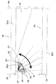
一方、図7は、図4に示すように各棚30に設けられるLED照明装置20においてLED素子21からの光の照射角度を下側の棚30の前側となるように調整した状態から、各棚30を所定の角度を成して陳列室11内に架設されている状態を示している。図に示すように、LED照明装置20による光の照射角度を図4の状態を維持したまま、各棚30が後方から前方に向けて低く傾斜して架設されると、上側の棚30の前端は下側の棚30の前端よりも奥側に移動するため、各棚30に設けられるLED照明装置20のLED素子21は、下側の棚30の前部よりも後方を照明することとなる。
On the other hand, in FIG. 7, each
そのため、棚30の手前側から商品が陳列されている場合、上側の棚30に設けられるLED照明装置20によって、棚30の前部に陳列されている商品を照明することができないこととなり、照明効果が著しく低減される。そのため、この場合、使用者は、それぞれの棚30に設けられるLED照明装置20の照射角度を調整する必要がある。
Therefore, when a product is displayed from the front side of the
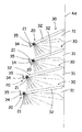
尚、図8では、従来、棚30に設けられていた蛍光灯100による照明範囲を示しているものであり、当該蛍光灯100は、蛍光管の外周全範囲から光が照射されるため、このようなことが生じがたい。
Note that FIG. 8 shows an illumination range by the
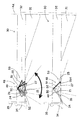
以下、図9及び図10を参照して他の実施例としてのLED照明装置48について説明する。図9は棚30(傾斜架設)に取り付けられたLED照明装置48による照明範囲を示すショーケース1の部分概略断面図、図10は棚30(略水平架設)に取り付けられた状態の部分拡大図をそれぞれ示している。
Hereinafter, with reference to FIG.9 and FIG.10, the
各棚30を構成する棚板32の下面前部には、上記図4の実施例と同様に棚板32の長手方向に渡って、LED照明装置48が設けられている。尚、この場合も、図4の場合と同様に棚板32が下面に開口する矩形状にて構成されている例について説明する。
An
係るLED照明装置48は、図4の実施例におけるLED素子21及び基板26を備えたLED素子取付部24及び反射部25によりLED照明取付部53が構成されるものであり、当該LED照明取付部53の両端部には、回動孔50が形成される側面51が形成されている。そして、棚板32の両側部であって棚板32の載置面の下面前部には、それぞれ保持部材49、49が設けられており、両回動孔50に挿通される回動軸52により回動自在に設けられる。
The
このとき、保持部材49へは、当該LED照明取付部53の自重で回動自在に設けられる。尚、本実施例では、LED照明装置48は、その重心が真下を向くように構成されている。そのため、棚30が略水平に架設された状態では、その重心によりLED素子21の照射範囲が下側の棚30の前部とする位置とされ、本実施例では、シェード27が棚板32の下端(下面開口)と略面一(水平)とされる。
At this time, the holding
係る構成により、棚30が後方から前方に向けて低く傾斜して架設されると、LED照明取付部53は、その重心が常に真下を向くため、LED素子21が下側の棚30の前部を照射範囲とすることができる。従って、図10に示すように、棚30が架設される傾斜角度に応じて、LED照明取付部53は、重心によって真下を向き、棚30下面に設けられるLED取付部材53の直ぐ下方を照明することが可能となる。
With such a configuration, when the
これにより、棚30の架設角度が任意に変更された場合であっても、格別にLED照明取付部53の取付角度の調整作業を行うことなく、棚30の下方に位置する陳列室11内を効果的に照明することが可能となる。特に、棚30の傾斜角度が大きくなるほど、下側の棚30前部を照明することにより得られる効果が大きくなるため、当該構成は有効となる。
Thereby, even if the erection angle of the
図11は、他の実施例としてのLED照明装置55を示している。このLED照明装置55は、棚32の前部下面に設けられる保持部材56が前後方向に延在する長孔57が形成されているものである。本実施例におけるLED照明取付部54は、上記実施例におけるLED照明装置48のLED照明取付部53の側面51に、少なくとも保持部材56側に延在する回動軸58が設けられたものである。この回動軸58は、保持部材56に形成される長孔57に対し、所定の抵抗をもって回動自在、且つ、奥行き方向に摺動自在に取り付けられている。
FIG. 11 shows an
係る構成により、棚30の下面前部に取り付けられるLED照明装置55は、LED取付部材54側の回動軸58を棚板32側の保持部材56の長孔57内において陳列室11の奥行き方向において移動自在とされているので、LED素子21が設けられるLED取付部材54の奥行き方向の取付位置を任意に、且つ、容易に変更することが可能となる。
With such a configuration, the
従って、棚30下方に位置する陳列室11内の商品の陳列状況に応じてLED素子21の取付位置を調整でき、且つ、前方から後方に向けて奥行き方向に回動自在に構成されているため、より効果的に商品の照明を実現することが可能となる。
Therefore, the mounting position of the
図12は、他の実施例としてのLED照明装置60の拡大断面図を示している。係る実施例では、棚30の下面前部であって両側部には、奥行き方向に延在する摺動部材61、61を備えている。また、この場合、LED照明装置60は、上記図4の実施例におけるLED素子21及び基板26を備えたLED素子取付部24と、その前端に所定角度(本実施例では約90°)を成して取り付けられる反射部25から成るLED取付部材62を有している。そして、このLED取付部材62のLED素子取付部24が摺動部材57の下面に奥行き方向に摺動自在に取り付けられている。
FIG. 12 shows an enlarged cross-sectional view of an
これにより、棚30の下面前部に取り付けられるLED取付部材62は、棚30に設けられる摺動部材61によって陳列室11の奥行き方向に任意に移動自在とされているので、LED素子21が設けられるLED照明装置60の奥行き方向の取付位置を任意に、且つ、容易に変更することが可能となる。
Thereby, the LED attachment member 62 attached to the front portion of the lower surface of the
従って、棚30下方に位置する陳列室11内の商品の陳列状況に応じてLED素子21の取付位置を調整でき、且つ、前方から後方に向けて奥行き方向に回動自在に構成されているため、より効果的に商品の照明を実現することが可能となる。
Therefore, the mounting position of the
尚、この場合、LED素子21は、棚30下面に水平に設けられて、奥行き方向に移動自在とされることとなるが、当該LED素子21から手前方向に向けて照射される光は、当該LED素子21の前方に設けられる反射部25の反射板25Aによって、効果的に棚30下の奥行き方向に照射することが可能となる。
In this case, the
なお、上述した如き各LED照明装置38、48、55、60は、従来用いられていた蛍光灯とは異なり、ちらつきが生じないため、安定した照明を行うことができ、適切な商品の照明を実現することができる。更に、LED素子21は、調光を容易に変更することが可能であるため、陳列室11内に陳列される商品に応じて、調光を変化させることで、より一層効果的な照明が可能となる。
In addition, since each
更にまた、LED素子21は、蛍光灯に比して、耐用年数が著しく長いため、照明の交換作業を不要とすることができる。そのため、交換部品の常備や交換によって排出される廃棄物の処理など煩雑な作業を不要とすることができる。
Furthermore, since the
また、本実施例では、所謂縦型のオープンショーケースにLED照明装置を取り付けたものを例として挙げているが、これに限定されるものではなく、平型のオープンショーケースであっても同様の効果を奏することが可能となる。 Further, in this embodiment, an example in which an LED lighting device is attached to a so-called vertical open showcase is given as an example, but the present invention is not limited to this, and the same applies to a flat open showcase. It is possible to achieve the effect.
1 ショーケース
2 断熱壁
4 仕切板
4A背部仕切板
11 陳列室
12 前面開口
20、24、28、38、48、55、60 LED照明装置
21 LED素子
22、29、53、54、62 LED取付部材
22A 枢支部材
23 棚取付部
24 LED素子取付部
25 反射部
25A 反射板
26、42 基板
27、46 シェード
30 棚
31 ブラケット
32 棚板
39 冷却器
41 照明取付部
41A 照明取付面
45 反射板
47、49、56 保持部材
50 回動孔
51 側面
52、58 回動軸
57 長孔
61 摺動部材
DESCRIPTION OF
Claims (4)
前記棚の下面に設けられ、当該棚の下方に陳列された商品を照明するLED素子を有するLED照明装置を備え、
該LED照明装置は、前記LED素子からの光の照射角度を、前記陳列室の奥行き方向において変更可能とされていることを特徴とするショーケース。 In a showcase where products are displayed on a multi-stage shelf installed in the display room,
Provided with an LED lighting device having an LED element that is provided on the lower surface of the shelf and illuminates products displayed below the shelf;
The LED lighting device is a showcase characterized in that an irradiation angle of light from the LED element can be changed in a depth direction of the display room.
該LED取付部材は、前記棚に対して回動自在に取り付けられていることを特徴とする請求項1に記載のショーケース。 The LED illumination device has an LED attachment member for attaching the LED element to the lower surface of the shelf,
The showcase according to claim 1, wherein the LED attachment member is rotatably attached to the shelf.
該LED取付部材は、前記陳列室の奥行き方向において移動自在とされていることを特徴とする請求項1乃至請求項3の何れかに記載のショーケース。 The LED illumination device has an LED attachment member for attaching the LED element to the lower surface of the shelf,
The showcase according to any one of claims 1 to 3, wherein the LED mounting member is movable in a depth direction of the display room.
Priority Applications (2)
| Application Number | Priority Date | Filing Date | Title |
|---|---|---|---|
| JP2008209681A JP5389396B2 (en) | 2008-08-18 | 2008-08-18 | Showcase |
| CN2009101509910A CN101653329B (en) | 2008-08-18 | 2009-07-01 | Showcase |
Applications Claiming Priority (1)
| Application Number | Priority Date | Filing Date | Title |
|---|---|---|---|
| JP2008209681A JP5389396B2 (en) | 2008-08-18 | 2008-08-18 | Showcase |
Publications (2)
| Publication Number | Publication Date |
|---|---|
| JP2010042191A true JP2010042191A (en) | 2010-02-25 |
| JP5389396B2 JP5389396B2 (en) | 2014-01-15 |
Family
ID=41707955
Family Applications (1)
| Application Number | Title | Priority Date | Filing Date |
|---|---|---|---|
| JP2008209681A Expired - Fee Related JP5389396B2 (en) | 2008-08-18 | 2008-08-18 | Showcase |
Country Status (2)
| Country | Link |
|---|---|
| JP (1) | JP5389396B2 (en) |
| CN (1) | CN101653329B (en) |
Families Citing this family (2)
| Publication number | Priority date | Publication date | Assignee | Title |
|---|---|---|---|---|
| JP6318369B2 (en) * | 2013-03-07 | 2018-05-09 | パナソニックIpマネジメント株式会社 | Cooker |
| CN107048877A (en) * | 2017-04-25 | 2017-08-18 | 无锡市龙海杰机械制造有限公司 | Put the supermarket shelves that goods plate installs reverse shot-light |
Citations (6)
| Publication number | Priority date | Publication date | Assignee | Title |
|---|---|---|---|---|
| JPH01193582A (en) * | 1988-12-12 | 1989-08-03 | Fuji Electric Co Ltd | Illuminating device for rack in showcase |
| JPH103814A (en) * | 1996-06-12 | 1998-01-06 | Toshiba Lighting & Technol Corp | Luminaire and lighting system |
| JP2006236796A (en) * | 2005-02-25 | 2006-09-07 | Mitsubishi Electric Corp | Lighting fixture and lighting system |
| JP2007215572A (en) * | 2006-02-14 | 2007-08-30 | Sanyo Electric Co Ltd | Showcase |
| JP2008210668A (en) * | 2007-02-27 | 2008-09-11 | Okamura Corp | Lighting system in merchandise display shelf |
| JP2008210666A (en) * | 2007-02-27 | 2008-09-11 | Okamura Corp | Lighting system in merchandise display shelf |
Family Cites Families (3)
| Publication number | Priority date | Publication date | Assignee | Title |
|---|---|---|---|---|
| AU2005250875B2 (en) * | 2004-05-26 | 2010-07-01 | Gelcore Llc | Led lighting systems for product display cases |
| US8033129B2 (en) * | 2005-07-04 | 2011-10-11 | Hoshizaki Denki Kabushiki Kaisha | Showcase |
| WO2007043034A2 (en) * | 2005-10-14 | 2007-04-19 | Nualight Limited | An illuminator |
-
2008
- 2008-08-18 JP JP2008209681A patent/JP5389396B2/en not_active Expired - Fee Related
-
2009
- 2009-07-01 CN CN2009101509910A patent/CN101653329B/en not_active Expired - Fee Related
Patent Citations (6)
| Publication number | Priority date | Publication date | Assignee | Title |
|---|---|---|---|---|
| JPH01193582A (en) * | 1988-12-12 | 1989-08-03 | Fuji Electric Co Ltd | Illuminating device for rack in showcase |
| JPH103814A (en) * | 1996-06-12 | 1998-01-06 | Toshiba Lighting & Technol Corp | Luminaire and lighting system |
| JP2006236796A (en) * | 2005-02-25 | 2006-09-07 | Mitsubishi Electric Corp | Lighting fixture and lighting system |
| JP2007215572A (en) * | 2006-02-14 | 2007-08-30 | Sanyo Electric Co Ltd | Showcase |
| JP2008210668A (en) * | 2007-02-27 | 2008-09-11 | Okamura Corp | Lighting system in merchandise display shelf |
| JP2008210666A (en) * | 2007-02-27 | 2008-09-11 | Okamura Corp | Lighting system in merchandise display shelf |
Also Published As
| Publication number | Publication date |
|---|---|
| JP5389396B2 (en) | 2014-01-15 |
| CN101653329B (en) | 2011-12-21 |
| CN101653329A (en) | 2010-02-24 |
Similar Documents
| Publication | Publication Date | Title |
|---|---|---|
| JP5311798B2 (en) | Showcase | |
| US7824057B2 (en) | Showcase | |
| JP4832335B2 (en) | Showcase | |
| EP1961341B1 (en) | Showcase | |
| EP1961339A1 (en) | Open showcase | |
| JP2009195273A (en) | Showcase | |
| US20080205040A1 (en) | Open showcase | |
| JP2001050650A (en) | Showcase | |
| JP5312841B2 (en) | Showcase | |
| JP5389410B2 (en) | Showcase | |
| US7572025B2 (en) | Showcase | |
| JP5389396B2 (en) | Showcase | |
| JP2010075243A (en) | Showcase | |
| JP5335348B2 (en) | Showcase | |
| JP2010084987A (en) | Showcase | |
| JP2010078250A (en) | Showcase | |
| JP5944217B2 (en) | Lighting device | |
| JP2005285701A (en) | Commodity showcase structure | |
| EP2168461A1 (en) | Display apparatus | |
| JP5191037B2 (en) | Open showcase | |
| JP2009005811A (en) | Showcase | |
| JP2010071622A (en) | Showcase | |
| JP2015146919A (en) | open showcase | |
| JP5619512B2 (en) | Showcase | |
| JP2010082116A (en) | Showcase |
Legal Events
| Date | Code | Title | Description |
|---|---|---|---|
| A621 | Written request for application examination |
Free format text: JAPANESE INTERMEDIATE CODE: A621 Effective date: 20110801 |
|
| A977 | Report on retrieval |
Free format text: JAPANESE INTERMEDIATE CODE: A971007 Effective date: 20130227 |
|
| A131 | Notification of reasons for refusal |
Free format text: JAPANESE INTERMEDIATE CODE: A131 Effective date: 20130409 |
|
| TRDD | Decision of grant or rejection written | ||
| A01 | Written decision to grant a patent or to grant a registration (utility model) |
Free format text: JAPANESE INTERMEDIATE CODE: A01 Effective date: 20130910 |
|
| A61 | First payment of annual fees (during grant procedure) |
Free format text: JAPANESE INTERMEDIATE CODE: A61 Effective date: 20131009 |
|
| R151 | Written notification of patent or utility model registration |
Ref document number: 5389396 Country of ref document: JP Free format text: JAPANESE INTERMEDIATE CODE: R151 |
|
| LAPS | Cancellation because of no payment of annual fees |