JP2010040579A - Article with protective cover capable of opening and closing - Google Patents
Article with protective cover capable of opening and closing Download PDFInfo
- Publication number
- JP2010040579A JP2010040579A JP2008198571A JP2008198571A JP2010040579A JP 2010040579 A JP2010040579 A JP 2010040579A JP 2008198571 A JP2008198571 A JP 2008198571A JP 2008198571 A JP2008198571 A JP 2008198571A JP 2010040579 A JP2010040579 A JP 2010040579A
- Authority
- JP
- Japan
- Prior art keywords
- protective cover
- rotating shaft
- main body
- article
- polygon
- Prior art date
- Legal status (The legal status is an assumption and is not a legal conclusion. Google has not performed a legal analysis and makes no representation as to the accuracy of the status listed.)
- Granted
Links
Images


Abstract
Description
本発明は、簡単な構造で耐久性に優れた、複数の静止安定位置で開閉可能な保護カバー付き物品に関する。 The present invention relates to an article with a protective cover that has a simple structure and excellent durability and can be opened and closed at a plurality of stationary stable positions.
従来から電気機器等の物品には、その一部を保護するために開閉可能な保護カバーが設けられることがある。かかる保護カバーは、急激な開閉動作を避けるために複数の静止安定位置を経て開閉されることが望まれる。また、高級感の観点から、保護カバーの開閉動作時には、静止安定位置間で適度なクリック感を伴うことが望まれる。さらに、安全性の観点から、保護カバーに必要以上の力が加えられたときに保護カバーが本体から容易に着脱できることが望まれる。 Conventionally, an article such as an electric device may be provided with a protective cover that can be opened and closed to protect a part of the article. Such a protective cover is desirably opened and closed through a plurality of stationary stable positions in order to avoid a sudden opening and closing operation. Further, from the viewpoint of a high-class feeling, it is desired that an appropriate click feeling is provided between the stationary stable positions when the protective cover is opened and closed. Furthermore, from the viewpoint of safety, it is desired that the protective cover can be easily attached to and detached from the main body when an excessive force is applied to the protective cover.
しかしながら、上述の希望の技術を全て盛り込んだ保護カバーを作製すると、構造が複雑になるか又は繰り返しの利用に対して耐久性に劣るという問題があった。 However, when a protective cover incorporating all of the desired technologies described above is produced, there is a problem that the structure becomes complicated or the durability is inferior to repeated use.
本発明は、かかる従来技術の問題に鑑み創案されたものであり、その目的は、簡単な構造で耐久性に優れた、複数の静止安定位置で開閉可能な保護カバー付き物品を提供することにある。また、本発明は、開閉可能な保護カバーが物品の本体から容易に着脱できる、保護カバー付き物品を提供することを目的とする。 The present invention has been made in view of the problems of the prior art, and an object of the present invention is to provide an article with a protective cover that can be opened and closed at a plurality of stable stable positions with a simple structure and excellent durability. is there. It is another object of the present invention to provide an article with a protective cover in which an openable / closable protective cover can be easily detached from the article body.
本発明者は、かかる目的を達成するために鋭意検討した結果、保護カバーを本体に連結する着脱自在な連結部材に、保護カバーに開閉動作を与える回転軸とその軸を圧接して係合しうる軸保持部材とを設けることによって、複数の静止安定位置でクリック感を伴いながら安全に開閉可能な保護カバー付き物品を提供することを見出し、本発明の完成に至った。 As a result of diligent investigations to achieve the above object, the present inventor has engaged a detachable connecting member that connects the protective cover to the main body by press-contacting the rotating shaft that gives the protective cover an opening / closing operation and the shaft. It has been found that an article with a protective cover that can be opened and closed safely with a click feeling at a plurality of stationary positions by providing a shaft holding member that can be opened and closed has been completed.
即ち、本発明は、本体と、前記本体の一部を保護するための開閉可能な保護カバーとを含む物品であって、
前記保護カバーは、開閉動作時に開放位置と閉鎖位置とそれらの位置の間の少なくとも一つの位置とを含む少なくとも三つの静止安定位置をとることができ、
前記保護カバーは、回転軸と軸保持部材とからなる連結部材を介して前記本体に連結され、
前記保護カバーは、前記回転軸の両軸端を固定して受ける部分を有し、前記回転軸が回転することにより前記保護カバーが回転して開閉動作を行い、
前記軸保持部材は、弾性部材によって前記回転軸の軸方向に沿った表面を圧接し、前記回転軸が回転する間に前記回転軸の軸方向に沿った表面とそれを圧接する前記軸保持部材の表面とが互いに係合して静止安定する少なくとも三つの位置をとり、それらの位置のときに前記保護カバーの前記静止安定位置をもたらす、
ことを特徴とする物品である。
That is, the present invention is an article including a main body and an openable / closable protective cover for protecting a part of the main body,
The protective cover can take at least three stationary stable positions including an open position, a closed position, and at least one position between these positions during opening and closing operations;
The protective cover is connected to the main body via a connecting member including a rotating shaft and a shaft holding member,
The protective cover has a portion that receives both ends of the rotary shaft fixedly, and the protective cover rotates and opens and closes when the rotary shaft rotates,
The shaft holding member presses the surface along the axial direction of the rotating shaft by an elastic member, and the shaft holding member presses the surface along the axial direction of the rotating shaft while the rotating shaft rotates. Take at least three positions where the surfaces of the protective cover engage with each other and become stable and provide the stationary stable position of the protective cover at those positions;
It is an article characterized by this.
本発明の物品の好ましい態様では、前記回転軸の軸方向横断面は多角形であり、前記回転軸の軸方向に沿った表面を圧接する軸保持部材の表面は、前記多角形の辺に合わせて接触できる平面部からなり、前記多角形の辺と前記平面部が互いに係合して静止安定位置をとる。 In a preferred aspect of the article of the present invention, the axial cross section of the rotating shaft is polygonal, and the surface of the shaft holding member that presses the surface along the axial direction of the rotating shaft is aligned with the side of the polygon. The polygonal side and the plane part engage with each other to obtain a stationary stable position.
本発明の物品の好ましい態様では、前記回転軸の軸方向横断面は多角形であり、前記回転軸の軸方向に沿った表面を圧接する軸保持部材の表面は、前記多角形の角に合わせて接触できる凹部からなり、前記多角形の角と前記凹部が互いに係合して静止安定位置をとる。 In a preferred aspect of the article of the present invention, the axial cross section of the rotating shaft is a polygon, and the surface of the shaft holding member that presses the surface along the axial direction of the rotating shaft is aligned with the corner of the polygon. The polygon corners and the recesses engage with each other to obtain a stationary stable position.
本発明の物品の好ましい態様では、前記凹部は略V字形であり、前記V字形を構成する二つの辺が前記多角形の隣接する二つの角をそれぞれ互いに均等に受けて係合してさらなる静止安定位置をとる。 In a preferred aspect of the article of the present invention, the recess is substantially V-shaped, and the two sides constituting the V-shape receive the two adjacent corners of the polygon equally to engage with each other, thereby further stationary. Take a stable position.
本発明の物品の好ましい態様では、前記回転軸の軸方向横断面の多角形であり、前記回転軸の軸方向に沿った表面を圧接する軸保持部材の表面は、前記多角形の角に合わせて接触できる凹部とその両側に形成された前記多角形の辺に合わせて接触できる平面部とからなり、前記多角形の角と前記凹部、又は前記多角形の辺と前記平面部が互いに係合して静止安定位置をとる。 In a preferred aspect of the article of the present invention, the surface of the shaft holding member that presses the surface along the axial direction of the rotating shaft is a polygon with a cross section in the axial direction of the rotating shaft aligned with the corner of the polygon. A concave portion that can be contacted with each other and a flat surface portion that can be brought into contact with the sides of the polygon formed on both sides thereof, and the corner of the polygon and the concave portion, or the side of the polygon and the flat surface portion are engaged with each other. And take a stationary stable position.
本発明の物品の好ましい態様では、前記凹部は略V字形であり、凹部のV字を構成する二つの辺とそれらにそれぞれ連続してつながる両側の平面部の間に形成された二つの角が前記多角形の隣接する二つの辺をそれぞれ互いに受けて係合してさらなる静止安定位置をとる。 In a preferred aspect of the article of the present invention, the concave portion is substantially V-shaped, and two corners formed between two sides constituting the V-shape of the concave portion and both flat portions continuously connected to each of them are provided. Two adjacent sides of the polygon are received and engaged with each other to obtain a further stationary stable position.
本発明の物品の好ましい態様では、前記連結部材は、前記本体に設けた凹所に収納され、前記凹所内で前記本体と連結されている。 In a preferred aspect of the article of the present invention, the connecting member is housed in a recess provided in the main body, and is connected to the main body within the recess.
本発明の物品の好ましい態様では、前記連結部材は、好ましくは前記本体の重量未満の力で本体からはずれるように着脱可能に連結されている。 In a preferred aspect of the article of the present invention, the connecting member is detachably connected so as to be detached from the main body with a force less than the weight of the main body.
本発明の物品の好ましい態様では、前記連結部材に雄部又は雌部が設けられ、前記本体の凹所内にそれらにそれぞれ対応した雌部又は雄部が設けられ、前記連結部材に設けた雄部又は雌部はそれぞれ、前記本体の凹所内に設けた雌部又は雄部に係合して前記連結部材と前記本体を連結する。 In a preferred aspect of the article of the present invention, the connecting member is provided with a male part or a female part, and a female part or a male part corresponding to each of them is provided in the recess of the main body, and the male part provided on the connecting member. Alternatively, each female part engages with a female part or a male part provided in the recess of the main body to connect the connecting member and the main body.
本発明の物品の好ましい態様では、前記連結部材に設けた雄部又は前記本体の凹所内に設けた雄部は板バネによって形成される。 In a preferred aspect of the article of the present invention, the male part provided in the connecting member or the male part provided in the recess of the main body is formed by a leaf spring.
本発明の物品の好ましい態様では、前記本体は電気機器であり、前記保護カバーは前記電気機器の操作盤を保護する。 In a preferred aspect of the article of the present invention, the main body is an electric device, and the protective cover protects an operation panel of the electric device.
本発明の物品は、保護カバーを回転する回転軸とそれを圧接する軸保持部材とが互いに係合して保護カバーの開閉動作時の静止安定位置をもたらすので、簡単な構造で複数の静止安定位置で保護カバーを安全に開閉することができる。また、本発明の物品は、回転軸の横断面が多角形であり、それを圧接する軸保持部材がその多角形の角又は辺を受けて静止安定する形状を有しているので、開閉動作時の複数の位置間でクリック感を伴うとともに繰り返しの開閉動作時に対する耐久性が高い。さらに、本発明の物品は、保護カバーの開閉動作の役割を持つ連結部材が本体に着脱自在に連結されているので、保護カバーに無理な力が掛かった場合に保護カバーが容易にはずれる。 In the article of the present invention, the rotating shaft that rotates the protective cover and the shaft holding member that presses the rotating shaft are engaged with each other to provide a stationary stable position when the protective cover is opened and closed. The protective cover can be opened and closed safely at the position. Further, the article of the present invention has a polygonal cross section of the rotating shaft, and the shaft holding member that presses the rotating shaft has a shape that is stationary and receives the corners or sides of the polygon. With a click feeling between multiple positions at the same time and high durability against repeated opening and closing operations. Furthermore, since the connecting member having the role of opening and closing the protective cover is detachably connected to the main body of the article of the present invention, the protective cover is easily removed when an excessive force is applied to the protective cover.
本発明の保護カバー付き物品の実施態様を図面を参照して以下に詳細に示すが、本発明はこれらに限定されるものではない。 Embodiments of the article with a protective cover of the present invention will be described below in detail with reference to the drawings, but the present invention is not limited thereto.
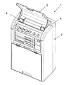
本発明の物品は、図1に示すように、本体2と、その一部を保護するための開閉可能な保護カバー3とを含む物品1であり、例えば、屋外で使用されるワイヤレスアンプなどの電気機器と、その操作盤を水、ほこり、日光等の環境的要因や人間等の接触による誤動作から保護するための開閉可能な保護カバーとからなる物品が該当する。
As shown in FIG. 1, the article of the present invention is an article 1 including a
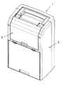
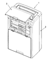
本発明の物品の保護カバー3は、開閉動作時に図1のような開放位置と、図2のような閉鎖位置と、図3のようなそれらの位置の間の中途の位置とを含む少なくとも三つの静止安定位置をとることができ、開放位置と閉鎖位置の間の静止安定位置は希望により必要な数だけ増加することができる。
The
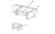
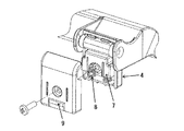
保護カバー3は、図1に示すように、連結部材4を介して本体に連結されるが、保護カバー3の開閉時等に無理な力が掛かった場合(例えば保護カバーをつかんで本体を持ち上げようとしたとき)に保護カバー等の物品の破損を避けるために、図4のように本体の重量未満の力で着脱できるようにすることが好ましい。また、連結部材4は、外部から目立たないようにするため、図4に示すように、本体2に設けた凹所5に収納され、その凹所5内で本体2と着脱自在に連結されることが好ましい。
As shown in FIG. 1, the
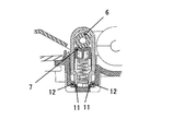
連結部材4は、図5(a),(b)の外部カバーを取りはずした分解図からわかるように、回転軸6と軸保持部材7とからなり、軸保持部材7は弾性部材8(図ではばね)によって回転軸6の軸方向に沿った表面を圧接するようになっている。回転軸6は保護カバー3によってその両軸端を固定して受けるようになっており、回転軸6が軸まわりに回転することによって保護カバー3が連動して回転して開閉動作を行う。回転軸6の回転角度範囲は、一般に45°以上270°以下、好ましくは60°以上180°以下である。
As can be seen from the exploded view with the outer cover removed in FIGS. 5A and 5B, the connecting
本発明では、回転軸6が回転する間に、回転軸6の軸方向に沿った表面とそれを圧接する軸保持部材7の表面とが互いに係合して静止安定する複数の位置をとるようになっており、これらの位置のときに保護カバー3の静止安定位置をもたらすようになっている。従って、これらの表面同士が互いに係合する静止安定位置の数を増加すれば、保護カバーの静止安定位置も同様に増加することができる。
In the present invention, while the
図5(c)を参照すると、本発明の連結部材4の一例の概略的断面図が示されている。図5(c)では、回転軸6の軸方向横断面は、多角形(図では八角形)であり、回転軸6の軸方向に沿った表面を圧接する軸保持部材7の表面は、この多角形の辺に合わせて接触できる平面部からなり、この平面部が多角形の辺と当接した安定状態で互いに係合することにより静止安定位置をとる。図5の態様では、もし回転軸6が1回転できるなら、八角形の辺の数の分だけ(即ち8ヶ所)の静止安定位置をとることができる。図5(c)の回転軸6の表面と軸保持部材7の表面の係合パターンは一例にすぎず、本発明の効果を損なわない限り、以下に説明する他の係合パターンも採用することができる。
Referring to FIG. 5C, a schematic cross-sectional view of an example of the connecting
図6(a)〜(d)を参照すると、本発明の連結部材4の別の例が示されている。図6(c)では、回転軸6の軸方向横断面は、多角形(図では八角形)であり、回転軸6の軸方向に沿った表面を圧接する軸保持部材7の表面は、この多角形の角に合わせて接触できる略V字形の凹部からなり、この凹部が多角形の角とぴったりと当接した状態で互いに係合することにより静止安定位置をとる。この態様では、図6(c)の静止安定位置以外に、図6(d)のように、V字形の凹部がV字を構成する二つの辺でそれぞれ多角形の隣接する角を均等に受けて係合する場合も静止安定位置をとることができる。図6の態様では、もし回転軸6が1回転できるなら、八角形の辺の2倍の数の分だけ(即ち16ヶ所)の静止安定位置をとることができる。
6 (a) to 6 (d), another example of the connecting
また、図7(a)〜(d)を参照すると、本発明の連結部材4のさらに別の例が示されている。図7(c)では、回転軸6の軸方向横断面は、多角形(図では八角形)であり、回転軸6の軸方向に沿った表面を圧接する軸保持部材7の表面は、この多角形の角に合わせて接触できる略V字形の凹部とその両側に形成されたこの多角形の辺に合わせて接触できる平面部とからなる。この場合、図7(c)に示すように、多角形の辺に合わせて凹部の両側の平面部が当接した安定状態で互いに係合するか、又は図7(d)に示すように、凹部のV字を構成する二つの辺とそれらにそれぞれ連続してつながる両側の平面部の間に形成された二つの角で多角形の隣接する辺を均等に受けて係合することによって静止安定位置をとることができる。図7の態様では、もし回転軸6が1回転できるなら、八角形の辺の2倍の数の分だけ(即ち16ヶ所)の静止安定位置をとることができる。
7A to 7D, still another example of the connecting
図5〜7の態様で示したように、回転軸6と軸保持部材7の係合パターンとしては、例えば、回転軸6の軸方向横断面が多角形(好ましくは六角形以上)であるとき、回転軸6の軸方向に沿った表面を圧接する軸保持部材7の表面が、多角形の辺を当接して受ける平面部、多角形の角を谷部で当接して受ける略V字形の凹部、多角形の二つの角をそれぞれ均等に受ける二つの辺からなる略V字形の凹部、又は多角形の二つの辺をそれぞれ均等に受ける二つの角を有する凹部と平面部からなる表面が挙げられる。最初の二つの態様は面同士が接触し、最後の二つの態様は二箇所で点同士が接触するが、面同士の接触の方が二点接触の場合より回転軸の静止安定度が高い。これらの係合パターンを採用することにより、回転軸の回転時に回転軸の多角形の角と辺が軸保持部材の表面と接触するときに適度なクリック感を伴うようになっている。また、軸保持部材7の多角形の内角は鈍角になるように、好ましくは120°以上に設定すると、多数回の開閉動作でも回転軸の多角形の角が大きな力を受けて欠けることが少ないので好ましい。
5-7, as an engagement pattern of the
本発明の連結部材4は、保護カバー3に複数の静止安定位置を伴う開閉機構を有するだけでなく、保護カバー3に無理な力が掛かったときに本体2から容易に着脱できる着脱機構も併せ持つ。この着脱機構は、連結部材4に設けられた雄部又は雌部と、本体2の凹部5内に設けられたそれらの雄部又は雌部にそれぞれ対応する雌部又は雄部とによって行われ、これらがそれぞれ互いに係合したり又は脱係合したりすることにより連結部材4と本体2の連結又は非連結が達成される。
The connecting
連結部材4の本体2からの着脱機構の例としては、図5(c)に示すように連結部材4に設けた雄部9と本体2の凹所5内に設けた雌部10が互いに係合して連結したり又は脱係合して脱連結するもの、図6(c)に示すように連結部材4に設けた雌部11と本体2の凹所5内に設けた雄部12が互いに係合して連結したり又は脱結合して脱連結するもの、図8に示すように連結部材4に設けた雌部13と本体2の凹所5内に設けた板バネによって形成された雄部14が互いに係合して連結したり又は脱係合して脱結合するものが挙げられる。連結部材4を本体2から着脱するための力はこの雌雄部の材料と大きさによって適宜設定することができるが、保護カバー3を無理な力で引っ張った場合でも本体2が追随しないように本体の重量未満の力ではずれることが好ましい。
As an example of the attaching / detaching mechanism of the connecting
本発明の物品は、簡単な構造で複数の静止安定位置で保護カバーをクリック感を伴いながら安全に開閉できるので、操作盤を保護する電気機器を始めとするあらゆる開閉部を有する製品に有用である。また、本発明の物品は、保護カバーが開閉機構を有する連結部材の部分から容易に脱着できるので、安全に取扱うことができる。 Since the article of the present invention can be safely opened and closed with a click feeling with a simple structure at a plurality of stationary stable positions, the article of the present invention is useful for products having all opening and closing parts such as electric devices for protecting the operation panel. is there. Further, the article of the present invention can be handled safely because the protective cover can be easily detached from the connecting member having the opening / closing mechanism.
1 物品
2 本体
3 保護カバー
4 連結部材
5 凹部
6 回転軸
7 軸保持部材
8 弾性部材
9 雄部
10 雌部
11 雌部
12 雄部
13 雌部
14 雄部(板バネ)
DESCRIPTION OF SYMBOLS 1
Claims (12)
前記保護カバーは、開閉動作時に開放位置と閉鎖位置とそれらの位置の間の少なくとも一つの位置とを含む少なくとも三つの静止安定位置をとることができ、
前記保護カバーは、回転軸と軸保持部材とからなる連結部材を介して前記本体に連結され、
前記保護カバーは、前記回転軸の両軸端を固定して受ける部分を有し、前記回転軸が回転することにより前記保護カバーが回転して開閉動作を行い、
前記軸保持部材は、弾性部材によって前記回転軸の軸方向に沿った表面を圧接し、前記回転軸が回転する間に前記回転軸の軸方向に沿った表面とそれを圧接する前記軸保持部材の表面とが互いに係合して静止安定する少なくとも三つの位置をとり、それらの位置のときに前記保護カバーの前記静止安定位置をもたらす、
ことを特徴とする物品。 An article including a main body and an openable / closable protective cover for protecting a part of the main body,
The protective cover can take at least three stationary stable positions including an open position, a closed position, and at least one position between these positions during opening and closing operations;
The protective cover is connected to the main body via a connecting member including a rotating shaft and a shaft holding member,
The protective cover has a portion that receives both ends of the rotary shaft fixedly, and the protective cover rotates and opens and closes when the rotary shaft rotates,
The shaft holding member presses the surface along the axial direction of the rotating shaft by an elastic member, and the shaft holding member presses the surface along the axial direction of the rotating shaft while the rotating shaft rotates. Take at least three positions where the surfaces of the protective cover engage with each other and become stable and provide the stationary stable position of the protective cover at those positions;
Article characterized by that.
Priority Applications (1)
| Application Number | Priority Date | Filing Date | Title |
|---|---|---|---|
| JP2008198571A JP5049909B2 (en) | 2008-07-31 | 2008-07-31 | Articles with protective covers that can be opened and closed |
Applications Claiming Priority (1)
| Application Number | Priority Date | Filing Date | Title |
|---|---|---|---|
| JP2008198571A JP5049909B2 (en) | 2008-07-31 | 2008-07-31 | Articles with protective covers that can be opened and closed |
Publications (2)
| Publication Number | Publication Date |
|---|---|
| JP2010040579A true JP2010040579A (en) | 2010-02-18 |
| JP5049909B2 JP5049909B2 (en) | 2012-10-17 |
Family
ID=42012853
Family Applications (1)
| Application Number | Title | Priority Date | Filing Date |
|---|---|---|---|
| JP2008198571A Active JP5049909B2 (en) | 2008-07-31 | 2008-07-31 | Articles with protective covers that can be opened and closed |
Country Status (1)
| Country | Link |
|---|---|
| JP (1) | JP5049909B2 (en) |
Cited By (1)
| Publication number | Priority date | Publication date | Assignee | Title |
|---|---|---|---|---|
| JP2013065140A (en) * | 2011-09-16 | 2013-04-11 | Panasonic Corp | Input unit and input device with the same |
Citations (7)
| Publication number | Priority date | Publication date | Assignee | Title |
|---|---|---|---|---|
| JPS60187572U (en) * | 1984-05-21 | 1985-12-12 | 松下電器産業株式会社 | Cover opening/closing device |
| JPH0582981A (en) * | 1991-09-20 | 1993-04-02 | Mitsubishi Electric Corp | Lid fitting device for electric equipment |
| JPH05335996A (en) * | 1992-06-03 | 1993-12-17 | Matsushita Electric Ind Co Ltd | Cover device for portable small sized ratio equipment |
| JPH06152159A (en) * | 1992-10-30 | 1994-05-31 | Polyplastics Co | Coupling utensil of lid body |
| JPH06310875A (en) * | 1993-04-27 | 1994-11-04 | Toshiba Corp | Hinge apparatus |
| JPH0772954A (en) * | 1993-09-03 | 1995-03-17 | Pfu Ltd | Tilt mechanism for portable computer |
| JPH1098277A (en) * | 1996-09-20 | 1998-04-14 | Kokusai Electric Co Ltd | Electronic equipment |
-
2008
- 2008-07-31 JP JP2008198571A patent/JP5049909B2/en active Active
Patent Citations (7)
| Publication number | Priority date | Publication date | Assignee | Title |
|---|---|---|---|---|
| JPS60187572U (en) * | 1984-05-21 | 1985-12-12 | 松下電器産業株式会社 | Cover opening/closing device |
| JPH0582981A (en) * | 1991-09-20 | 1993-04-02 | Mitsubishi Electric Corp | Lid fitting device for electric equipment |
| JPH05335996A (en) * | 1992-06-03 | 1993-12-17 | Matsushita Electric Ind Co Ltd | Cover device for portable small sized ratio equipment |
| JPH06152159A (en) * | 1992-10-30 | 1994-05-31 | Polyplastics Co | Coupling utensil of lid body |
| JPH06310875A (en) * | 1993-04-27 | 1994-11-04 | Toshiba Corp | Hinge apparatus |
| JPH0772954A (en) * | 1993-09-03 | 1995-03-17 | Pfu Ltd | Tilt mechanism for portable computer |
| JPH1098277A (en) * | 1996-09-20 | 1998-04-14 | Kokusai Electric Co Ltd | Electronic equipment |
Cited By (1)
| Publication number | Priority date | Publication date | Assignee | Title |
|---|---|---|---|---|
| JP2013065140A (en) * | 2011-09-16 | 2013-04-11 | Panasonic Corp | Input unit and input device with the same |
Also Published As
| Publication number | Publication date |
|---|---|
| JP5049909B2 (en) | 2012-10-17 |
Similar Documents
| Publication | Publication Date | Title |
|---|---|---|
| USD639243S1 (en) | Electrode connector | |
| USD535055S1 (en) | Hair binder | |
| USD535252S1 (en) | Charger for electronic device | |
| USD548002S1 (en) | Grill with transparent cover | |
| US9089977B2 (en) | Compliant underactuated grasper | |
| USD604589S1 (en) | Cord lock | |
| USD605466S1 (en) | Barbeque temperature control | |
| USD554002S1 (en) | Watch | |
| USD618644S1 (en) | Telepresence display | |
| USD587988S1 (en) | Cord lock | |
| KR101487189B1 (en) | Hinge for flexible display device | |
| USD602938S1 (en) | Open-configured computer docking assembly with two pivot arms | |
| USD606570S1 (en) | Watch winding mechanism | |
| USD634268S1 (en) | Charger for an electric skin brush applicator | |
| USD626578S1 (en) | Robot head | |
| USD575859S1 (en) | Aromatic dispenser | |
| JP5049909B2 (en) | Articles with protective covers that can be opened and closed | |
| USD592238S1 (en) | Sunglasses lanyard | |
| USD571051S1 (en) | Glove | |
| US20130293072A1 (en) | Tablet and electronic media cover protector and handling apparatus | |
| USD611049S1 (en) | Blade information handling system chassis bezel | |
| USD587989S1 (en) | Cord lock | |
| JP3142447U (en) | Protective cover for danger prevention of playground equipment chain | |
| USD525112S1 (en) | Hinged protective cover with resilient receiving pads for padlock | |
| JP5195436B2 (en) | Tamper switch drive structure for outdoor equipment |
Legal Events
| Date | Code | Title | Description |
|---|---|---|---|
| A621 | Written request for application examination |
Free format text: JAPANESE INTERMEDIATE CODE: A621 Effective date: 20110524 |
|
| A977 | Report on retrieval |
Free format text: JAPANESE INTERMEDIATE CODE: A971007 Effective date: 20120704 |
|
| TRDD | Decision of grant or rejection written | ||
| A01 | Written decision to grant a patent or to grant a registration (utility model) |
Free format text: JAPANESE INTERMEDIATE CODE: A01 Effective date: 20120706 |
|
| A01 | Written decision to grant a patent or to grant a registration (utility model) |
Free format text: JAPANESE INTERMEDIATE CODE: A01 |
|
| A61 | First payment of annual fees (during grant procedure) |
Free format text: JAPANESE INTERMEDIATE CODE: A61 Effective date: 20120723 |
|
| FPAY | Renewal fee payment (event date is renewal date of database) |
Free format text: PAYMENT UNTIL: 20150727 Year of fee payment: 3 |
|
| R150 | Certificate of patent or registration of utility model |
Ref document number: 5049909 Country of ref document: JP Free format text: JAPANESE INTERMEDIATE CODE: R150 Free format text: JAPANESE INTERMEDIATE CODE: R150 |
|
| R250 | Receipt of annual fees |
Free format text: JAPANESE INTERMEDIATE CODE: R250 |
|
| R250 | Receipt of annual fees |
Free format text: JAPANESE INTERMEDIATE CODE: R250 |
|
| R250 | Receipt of annual fees |
Free format text: JAPANESE INTERMEDIATE CODE: R250 |
|
| R250 | Receipt of annual fees |
Free format text: JAPANESE INTERMEDIATE CODE: R250 |
|
| R250 | Receipt of annual fees |
Free format text: JAPANESE INTERMEDIATE CODE: R250 |
|
| R250 | Receipt of annual fees |
Free format text: JAPANESE INTERMEDIATE CODE: R250 |
|
| R250 | Receipt of annual fees |
Free format text: JAPANESE INTERMEDIATE CODE: R250 |
|
| R250 | Receipt of annual fees |
Free format text: JAPANESE INTERMEDIATE CODE: R250 |
|
| R250 | Receipt of annual fees |
Free format text: JAPANESE INTERMEDIATE CODE: R250 |