JP2010040375A - Anode discharge reserve reduction method of battery module - Google Patents
Anode discharge reserve reduction method of battery module Download PDFInfo
- Publication number
- JP2010040375A JP2010040375A JP2008203027A JP2008203027A JP2010040375A JP 2010040375 A JP2010040375 A JP 2010040375A JP 2008203027 A JP2008203027 A JP 2008203027A JP 2008203027 A JP2008203027 A JP 2008203027A JP 2010040375 A JP2010040375 A JP 2010040375A
- Authority
- JP
- Japan
- Prior art keywords
- battery
- battery module
- unit
- oxygen
- negative electrode
- Prior art date
- Legal status (The legal status is an assumption and is not a legal conclusion. Google has not performed a legal analysis and makes no representation as to the accuracy of the status listed.)
- Pending
Links
- 238000000034 method Methods 0.000 title claims abstract description 27
- 230000009467 reduction Effects 0.000 title claims description 10
- 239000001301 oxygen Substances 0.000 claims abstract description 47
- 229910052760 oxygen Inorganic materials 0.000 claims abstract description 47
- QVGXLLKOCUKJST-UHFFFAOYSA-N atomic oxygen Chemical compound [O] QVGXLLKOCUKJST-UHFFFAOYSA-N 0.000 claims abstract description 46
- 239000001257 hydrogen Substances 0.000 claims abstract description 22
- 229910052739 hydrogen Inorganic materials 0.000 claims abstract description 22
- PXHVJJICTQNCMI-UHFFFAOYSA-N nickel Substances [Ni] PXHVJJICTQNCMI-UHFFFAOYSA-N 0.000 claims abstract description 20
- UFHFLCQGNIYNRP-UHFFFAOYSA-N Hydrogen Chemical compound [H][H] UFHFLCQGNIYNRP-UHFFFAOYSA-N 0.000 claims abstract description 17
- 230000004913 activation Effects 0.000 claims abstract description 13
- 229910052759 nickel Inorganic materials 0.000 claims abstract description 13
- -1 nickel hydrogen Chemical class 0.000 claims abstract description 11
- 238000004891 communication Methods 0.000 claims description 18
- 238000001816 cooling Methods 0.000 claims description 18
- 229910052987 metal hydride Inorganic materials 0.000 claims description 9
- 239000007773 negative electrode material Substances 0.000 claims description 9
- 239000007774 positive electrode material Substances 0.000 claims description 6
- MYMOFIZGZYHOMD-UHFFFAOYSA-N Dioxygen Chemical compound O=O MYMOFIZGZYHOMD-UHFFFAOYSA-N 0.000 description 19
- 229910001882 dioxygen Inorganic materials 0.000 description 19
- 239000007789 gas Substances 0.000 description 15
- 238000001994 activation Methods 0.000 description 11
- 238000006243 chemical reaction Methods 0.000 description 10
- 230000007246 mechanism Effects 0.000 description 7
- CIWBSHSKHKDKBQ-JLAZNSOCSA-N Ascorbic acid Chemical compound OC[C@H](O)[C@H]1OC(=O)C(O)=C1O CIWBSHSKHKDKBQ-JLAZNSOCSA-N 0.000 description 6
- 230000006866 deterioration Effects 0.000 description 6
- 239000000463 material Substances 0.000 description 6
- 229910052782 aluminium Inorganic materials 0.000 description 5
- XAGFODPZIPBFFR-UHFFFAOYSA-N aluminium Chemical compound [Al] XAGFODPZIPBFFR-UHFFFAOYSA-N 0.000 description 5
- 238000004519 manufacturing process Methods 0.000 description 5
- 238000005259 measurement Methods 0.000 description 5
- 229910045601 alloy Inorganic materials 0.000 description 4
- 239000000956 alloy Substances 0.000 description 4
- 238000009423 ventilation Methods 0.000 description 4
- 238000007600 charging Methods 0.000 description 3
- 238000010586 diagram Methods 0.000 description 3
- 239000008151 electrolyte solution Substances 0.000 description 3
- 238000012544 monitoring process Methods 0.000 description 3
- 229910000652 nickel hydride Inorganic materials 0.000 description 3
- 239000011230 binding agent Substances 0.000 description 2
- 239000004020 conductor Substances 0.000 description 2
- 239000002826 coolant Substances 0.000 description 2
- 238000007599 discharging Methods 0.000 description 2
- 238000006073 displacement reaction Methods 0.000 description 2
- 230000000694 effects Effects 0.000 description 2
- 150000002431 hydrogen Chemical class 0.000 description 2
- 125000004435 hydrogen atom Chemical group [H]* 0.000 description 2
- 238000007747 plating Methods 0.000 description 2
- 230000001105 regulatory effect Effects 0.000 description 2
- 229910002640 NiOOH Inorganic materials 0.000 description 1
- 229910000831 Steel Inorganic materials 0.000 description 1
- 239000011149 active material Substances 0.000 description 1
- 238000007792 addition Methods 0.000 description 1
- 230000002411 adverse Effects 0.000 description 1
- 239000007864 aqueous solution Substances 0.000 description 1
- 238000012937 correction Methods 0.000 description 1
- 230000007797 corrosion Effects 0.000 description 1
- 238000005260 corrosion Methods 0.000 description 1
- 238000000354 decomposition reaction Methods 0.000 description 1
- 238000012217 deletion Methods 0.000 description 1
- 230000037430 deletion Effects 0.000 description 1
- 238000003411 electrode reaction Methods 0.000 description 1
- 239000003792 electrolyte Substances 0.000 description 1
- 230000009931 harmful effect Effects 0.000 description 1
- 230000017525 heat dissipation Effects 0.000 description 1
- 239000011810 insulating material Substances 0.000 description 1
- 238000012986 modification Methods 0.000 description 1
- 230000004048 modification Effects 0.000 description 1
- BFDHFSHZJLFAMC-UHFFFAOYSA-L nickel(ii) hydroxide Chemical compound [OH-].[OH-].[Ni+2] BFDHFSHZJLFAMC-UHFFFAOYSA-L 0.000 description 1
- 230000003647 oxidation Effects 0.000 description 1
- 238000007254 oxidation reaction Methods 0.000 description 1
- 150000002926 oxygen Chemical class 0.000 description 1
- 230000005855 radiation Effects 0.000 description 1
- 239000003507 refrigerant Substances 0.000 description 1
- 230000001172 regenerating effect Effects 0.000 description 1
- 238000007789 sealing Methods 0.000 description 1
- 239000010959 steel Substances 0.000 description 1
Images


Classifications
-
- Y—GENERAL TAGGING OF NEW TECHNOLOGICAL DEVELOPMENTS; GENERAL TAGGING OF CROSS-SECTIONAL TECHNOLOGIES SPANNING OVER SEVERAL SECTIONS OF THE IPC; TECHNICAL SUBJECTS COVERED BY FORMER USPC CROSS-REFERENCE ART COLLECTIONS [XRACs] AND DIGESTS
- Y02—TECHNOLOGIES OR APPLICATIONS FOR MITIGATION OR ADAPTATION AGAINST CLIMATE CHANGE
- Y02E—REDUCTION OF GREENHOUSE GAS [GHG] EMISSIONS, RELATED TO ENERGY GENERATION, TRANSMISSION OR DISTRIBUTION
- Y02E60/00—Enabling technologies; Technologies with a potential or indirect contribution to GHG emissions mitigation
- Y02E60/10—Energy storage using batteries
Abstract
Description
本発明は、ニッケル水素二次電池モジュールの負極放電リザーブを、電池内に酸素を供給することによって低減する方法に関する。 The present invention relates to a method for reducing the negative electrode discharge reserve of a nickel metal hydride secondary battery module by supplying oxygen into the battery.
従来、主として携帯機器用の電源として使用する充放電可能な種々の二次電池が提案されてきた。さらには、近年、環境への配慮から、自動車や電車などの車両に充放電可能な二次電池を搭載したものが開発されている。車両に二次電池を搭載した場合には、ブレーキ時に生じる回生電力をこの搭載電池に蓄えておき、車両の動力源として使用することができるので、車両のエネルギー効率を高めることができる。このように車両に搭載する二次電池としては、エネルギー密度、負荷変動追従性、耐久性、製造コストなどの諸条件から、例えばニッケル水素二次電池が適しているとされる(特許文献1)。 Conventionally, various rechargeable secondary batteries used mainly as a power source for portable devices have been proposed. Furthermore, in recent years, a battery equipped with a rechargeable battery has been developed for vehicles such as automobiles and trains in consideration of the environment. When a secondary battery is mounted on a vehicle, regenerative power generated during braking can be stored in the mounted battery and used as a power source for the vehicle, so that the energy efficiency of the vehicle can be increased. Thus, for example, a nickel metal hydride secondary battery is considered suitable as a secondary battery mounted on a vehicle from various conditions such as energy density, load fluctuation followability, durability, and manufacturing cost (Patent Document 1). .
ニッケル水素二次電池の電極反応は、下記の式(1)および(2)で表される。それぞれ右向きの反応が充電反応、左向きの反応が放電反応であり、Mは水素吸蔵合金を表す。
正極:Ni(OH)2 + OH− ⇔ NiOOH + H2O + e− (1)
負極:M + H2O +e− ⇔ MH + OH− (2)
The electrode reaction of the nickel hydride secondary battery is expressed by the following formulas (1) and (2). The rightward reaction is a charging reaction and the leftward reaction is a discharge reaction, respectively, and M represents a hydrogen storage alloy.
Positive electrode: Ni (OH) 2 + OH − Ni NiOOH + H 2 O + e − (1)
Negative electrode: M + H 2 O + e − ⇔ MH + OH − (2)
ところで、ニッケル水素二次電池においては、一般的に、図1に示すように、あらかじめ負極の充電容量を正極の充電容量よりも大きく設定しておくことで、密閉化を可能にしている。この、負極における正極の充電容量を上回る分を、充電リザーブと呼ぶ。満充電の状態からさらに充電が行われる過充電時には、正極において下記(3)の反応により酸素ガスが発生する。
OH− → 1/4O2 + 1/2H2O + e− (3)
正極で発生した酸素ガスは、下記(4)の反応により負極の水素吸蔵合金(M)中の水素と反応してH2Oとなるので、電池内部の圧力上昇が抑えられ、電池を密閉構造とすることができる。
MH + 1/4O2 → M + 1/2H2O (4)
By the way, in a nickel metal hydride secondary battery, generally, as shown in FIG. 1, the negative electrode charge capacity is set to be larger than the positive electrode charge capacity in advance to enable sealing. The portion of the negative electrode that exceeds the charge capacity of the positive electrode is called charge reserve. At the time of overcharging in which charging is further performed from the fully charged state, oxygen gas is generated at the positive electrode by the reaction (3) below.
OH − → 1/4 O 2 + 1/2 H 2 O + e − (3)
The oxygen gas generated in the positive electrode reacts with hydrogen in the hydrogen storage alloy (M) of the negative electrode by the reaction (4) below to become H 2 O, so that the increase in pressure inside the battery is suppressed, and the battery is sealed. It can be.
MH + 1/4 O 2 → M + 1/2 H 2 O (4)
一方、放電側においても正極規制となるように、負極に予め多目の放電容量(つまり水素)を設けておく。これを放電リザーブと呼ぶ。通常、ニッケル水素二次電池は、組み立てられた直後は電池として十分に機能しないので、予備的な充放電(初期活性化)を行った後に出荷されるが、この初期活性化の過程で、正極に含まれる、活物質以外の導電材やバインダーなどの物質が酸化し、これによって発生する水素が放電リザーブとして負極に蓄えられる。 On the other hand, a large discharge capacity (that is, hydrogen) is provided in advance on the negative electrode so that the positive electrode is also regulated on the discharge side. This is called discharge reserve. Usually, a nickel metal hydride secondary battery does not function sufficiently as a battery immediately after it is assembled, so it is shipped after preliminary charge / discharge (initial activation). A material such as a conductive material and a binder other than the active material is oxidized and hydrogen generated thereby is stored in the negative electrode as a discharge reserve.
しかし、放電リザーブは、上述の初期活性化の後も、通常の充放電サイクルが進むにつれて、セパレータやバインダーの酸化、負極合金の腐食等によりさらに増加していく。このように放電リザーブが増加することにより、負極の充電容量が正極の充電容量よりも小さくなった場合には、充電末期に負極から水素ガスが発生し、内部圧力が急上昇してガス排出弁が作動する。また、放電リザーブの増大は、電解液(H2O)の分解によるものであるので、電解液のドライアウトによる電池寿命の低下を招く。さらには、このような放電リザーブの増加による弊害を防止するために、充電リザーブを大きく設定しようとすれば、実質的に電池容量に寄与しない余分な負極材料を充填しなければならないので、電池全体の体積エネルギ密度の低減を余儀なくされる。 However, even after the initial activation described above, the discharge reserve further increases due to oxidation of the separator and binder, corrosion of the negative electrode alloy, and the like as the normal charge / discharge cycle proceeds. When the discharge reserve increases in this way and the charge capacity of the negative electrode becomes smaller than the charge capacity of the positive electrode, hydrogen gas is generated from the negative electrode at the end of the charge, the internal pressure rapidly rises, and the gas discharge valve Operate. Moreover, since the increase in the discharge reserve is due to the decomposition of the electrolytic solution (H 2 O), the battery life is reduced due to the dry-out of the electrolytic solution. Furthermore, in order to prevent such an adverse effect due to the increase in the discharge reserve, if the charge reserve is set to be large, an extra negative electrode material that does not substantially contribute to the battery capacity must be filled. The volume energy density of the material is inevitably reduced.
本発明の目的は、上記の課題を解決して、ニッケル水素二次電池の寿命や充放電容量の向上を図るために、電池内に酸素を供給することによって初期活性化後の放電リザーブを低減する方法を提供することである。 The object of the present invention is to reduce the discharge reserve after the initial activation by supplying oxygen into the battery in order to solve the above problems and improve the life and charge / discharge capacity of the nickel metal hydride secondary battery. Is to provide a way to do.
前記した目的を達成するために、本発明に係る電池モジュールの負極放電リザーブ低減方法は、ニッケル水素二次電池として構成された単位電池と、前記単位電池の内部に連通する酸素供給源とを備えた電池モジュールの負極放電リザーブを低減する方法であって、前記単位電池の初期活性化充放電の後に、前記酸素供給源から前記単位電池の内部に酸素を供給して、負極に吸蔵された放電リザーブである水素と反応させることを含む。 To achieve the above object, a negative discharge reserve reduction method for a battery module according to the present invention includes a unit battery configured as a nickel hydride secondary battery and an oxygen supply source communicating with the inside of the unit battery. A method for reducing the negative discharge reserve of the battery module, wherein after the initial activation charge / discharge of the unit battery, oxygen is supplied from the oxygen supply source to the inside of the unit battery, and the discharge is occluded in the negative electrode. Reacting with hydrogen which is a reserve.
この構成によれば、初期活性化によって負極に蓄積された水素が、酸素供給源から供給される酸素と反応してH2Oとなって、負極の放電リザーブが低減されるので、電解液のドライアウトを防止して、電池性能、特には充放電サイクル寿命の劣化を防止することができる。また、初期段階での負極の放電リザーブを低減できることから、予め設定する充電リザーブの量、すなわち余分に充填する負極活物質の量をも低減することが可能となるので、電池全体の充放電容量を増大させることができる。 According to this configuration, the hydrogen accumulated in the negative electrode by the initial activation reacts with oxygen supplied from the oxygen supply source to become H 2 O, and the discharge reserve of the negative electrode is reduced. Dryout can be prevented, and deterioration of battery performance, in particular, charge / discharge cycle life can be prevented. In addition, since the discharge reserve of the negative electrode in the initial stage can be reduced, it is possible to reduce the amount of charge reserve set in advance, that is, the amount of the negative electrode active material to be additionally filled, so that the charge / discharge capacity of the entire battery can be reduced. Can be increased.
本発明に係る負極放電リザーブ低減方法においては、前記酸素供給源から前記単位電池の内部への酸素の供給量を、予め測定した負極放電リザーブ量に基づいて調節することが好ましい。このように構成することにより、適切な量の酸素を供給して効果的に放電リザーブを低減することができる。 In the negative electrode discharge reserve reducing method according to the present invention, it is preferable to adjust the supply amount of oxygen from the oxygen supply source to the inside of the unit battery based on a negative electrode discharge reserve amount measured in advance. By comprising in this way, an appropriate amount of oxygen can be supplied and discharge reserve can be reduced effectively.
本発明に係る上記の負極放電リザーブ低減方法において、前記電池モジュールに、前記単位電池を冷却する冷却構造を設け、この冷却構造によって前記単位電池を冷却しながら単位電池の内部に酸素を供給することが好ましい。放電リザーブである水素が酸素と反応してH2Oを生成する反応は発熱反応であるので、当該方法によって放電リザーブを低減する際には電池温度が上昇する。電池温度の上昇は、電池を構成する材料の劣化を招き、電池性能の低下をもたらすが、電池モジュールに冷却構造を設けることによりこのような弊害を排除することができる。 In the above-described negative electrode discharge reserve reduction method according to the present invention, the battery module is provided with a cooling structure for cooling the unit battery, and oxygen is supplied to the inside of the unit battery while cooling the unit battery by the cooling structure. Is preferred. Since the reaction in which hydrogen, which is the discharge reserve, reacts with oxygen to generate H 2 O is an exothermic reaction, the battery temperature rises when the discharge reserve is reduced by this method. An increase in battery temperature causes deterioration of materials constituting the battery and a decrease in battery performance. However, such a harmful effect can be eliminated by providing a cooling structure in the battery module.
本発明に係る負極放電リザーブ低減方法において、上記の冷却構造は、例えば、前記電池モジュールに、複数の前記単位電池を互いに電気的に接続し、かつ、その内部を、連通部材を介して互いに連通させてなる電池積層体を設け、該電池積層体の隣接する単位電池間に、単位電池の積層方向に直交して延びる貫通孔を有する放熱板を介在させることにより設けることができる。このように構成することにより、簡単な構造で、電池積層体の表面のみならず単位電池の積層面までも効果的に冷却して、電池モジュールの性能劣化を防止することができる。 In the method for reducing negative electrode discharge reserve according to the present invention, the cooling structure includes, for example, electrically connecting a plurality of the unit cells to the battery module and communicating the interior with each other via a communication member. The battery stack can be provided, and a heat dissipation plate having a through hole extending perpendicularly to the stacking direction of the unit cells can be provided between adjacent unit cells of the battery stack. With such a configuration, it is possible to effectively cool not only the surface of the battery stack but also the stack surface of the unit battery with a simple structure, and prevent performance deterioration of the battery module.
本発明に係る電池モジュールは、ニッケル水素二次電池として構成された単位電池と、前記単位電池の内部に連通する酸素供給源とを備え、上記の負極放電リザーブ低減方法によって負極放電リザーブが低減された電池モジュールであって、正極活物質の充填量に対する負極活物質の充填量の比が、容量換算で100〜400%の範囲内にある。上記の方法によって負極放電リザーブの低減が可能となるので、このように、予め正極活物質よりも余分に充填しておく負極活物質の充電リザーブ相当分を低減することも可能となり、電池モジュールの充放電容量を増加させることができる。 A battery module according to the present invention includes a unit battery configured as a nickel metal hydride secondary battery and an oxygen supply source that communicates with the inside of the unit battery, and the negative electrode discharge reserve is reduced by the negative electrode discharge reserve reduction method described above. The ratio of the filling amount of the negative electrode active material to the filling amount of the positive electrode active material is in a range of 100 to 400% in terms of capacity. Since the negative electrode discharge reserve can be reduced by the above method, it is possible to reduce the amount equivalent to the charge reserve of the negative electrode active material previously filled in excess of the positive electrode active material. The charge / discharge capacity can be increased.
以上のように、本発明に係る電池モジュールの負極放電リザーブ低減方法によれば、初期活性化後の放電リザーブを確実に低減して、電池モジュールの寿命や充放電容量の向上を図ることができる。 As described above, according to the negative discharge reserve reduction method for a battery module according to the present invention, the discharge reserve after the initial activation can be reliably reduced, and the life of the battery module and the charge / discharge capacity can be improved. .
以下、本発明に係る実施形態を図面に従って説明するが、本発明はこの実施形態に限定されるものではない。 Hereinafter, embodiments according to the present invention will be described with reference to the drawings. However, the present invention is not limited to the embodiments.
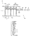
図2は、本発明の一実施形態に係る放電リザーブ低減方法が適用される電池モジュールを示す概略構成図である。この電池モジュールBは、例えば、電車に搭載されるものであって、ニッケル水素二次電池として構成された単位電池Cを、単位電池Cの厚み方向に複数個(本実施形態では30個)積層した電池積層体1、単位電池Cの内部を連通させる連通部材3、および連通部材3を介して各単位電池Cの内部に酸素を供給する酸素供給源5を主要な構成要素として備えており、これらが後述するハウジングによって覆われている。
FIG. 2 is a schematic configuration diagram illustrating a battery module to which the discharge reserve reduction method according to an embodiment of the present invention is applied. The battery module B is mounted on a train, for example, and a plurality of unit batteries C (30 in the present embodiment) stacked in the thickness direction of the unit battery C are stacked as nickel-hydrogen secondary batteries. The battery stack 1, the
図3は、図2の単位電池Cの構造の一例を示す断面図である。単位電池Cは、セパレータ21と、正極23および負極25を含む電極体27と、電極体27を電解液とともに収容する角形形状のケーシング29とを備えている。ケーシング29は、絶縁素材からなる矩形の枠形部材31と、枠形部材31の二つの開口をそれぞれ覆う、導電素材からなる第1蓋部材33および第2蓋部材35とから構成されている。
FIG. 3 is a cross-sectional view showing an example of the structure of the unit battery C of FIG. The unit battery C includes a
ケーシング29の枠形部材31の外面には、単位電池Cの内部と外部を連通させる連通口37が設けられている。連通口37は、連通口37が設けられている枠形部材31の一辺にほぼ平行に、枠形部材31の中央に向かって突出する二又の連通部37aを有しており、後述するように、電池モジュールBのガス供給系統39の一部を構成している。なお、本実施形態における単位電池Cは、水酸化ニッケルを主要な正極活物質とし、水素吸蔵合金を主要な負極活物質とし、アルカリ系水溶液を電解液とする、繰り返し充放電が可能なニッケル水素二次電池として構成している。
A
電極体27の構造は、特に限定されないが、例えば、複数の正極23と複数の負極25とが、プリーツ状に折り曲げられたセパレータ21を介して所定の方向に交互に積層されて対向する積層構造を有している。ケーシング29の第1蓋部材33および第2蓋部材35は、ニッケルめっきを施した鋼板で形成されており、正極23は第1蓋部材33に、負極25は第2蓋部材35に、それぞれ電気的に接続されている。つまり、第1および第2蓋部材33,35は、それぞれ、単位電池Cの正極集電体および負極集電体を兼ねている。なお、セパレータ21は、図3に示したプリーツ状のものに限らず、例えば、袋状のものを使用してもよい。
The structure of the
次に、単位電池Cを用いて構成した電池モジュールBの構造について説明する。本実施形態における電池モジュールBの電池積層体1は、図2に示すように、単位電池Cと、後述する構造の放熱板41とを積層したものである。単位電池Cは、隣接する単位電池Cの一方の第1蓋部材33と、他方の第2蓋部材35とが互いに対向する方向に積層されており、さらに、2つの単位電池Cに1つの割合で、放熱板41が介在している。
Next, the structure of the battery module B configured using the unit battery C will be described. As shown in FIG. 2, the
電池モジュールBには、各単位電池Cの内部に酸素ガスを供給するためのガス供給系統39が、以下のように構成されて設けられている。図2に示すように、各単位電池Cに設けられた各連通口37の二又の導入部37aのそれぞれが、隣接する単位電池Cの連通口37の導入部37aの一方と、ガス供給通路GSの一部分を形成する可撓性の連結チューブ51を介して順次接続されており、末端の単位電池Cの一方の導入部37aが、ガス供給通路GSの一部分を形成する導入チューブ52に設けられた流量監視用の流量計F、流量調整弁53、および流路開閉機構55を介して、酸素ガスの供給源となる酸素タンク57に接続されている。先端の単位電池Cの一方の導入部37aは、盲栓により閉塞する。これら連通口37、連通部材3である連結チューブ51および導入チューブ52、流量計F、流量調整弁53、流路開閉機構55ならびに酸素タンク57が、電池モジュールBのガス供給系統39を構成している。
In the battery module B, a
このようなに構成したガス供給系統39において、所定のモル数の酸素ガスが供給されたときに、流路開閉機構55により酸素ガスの供給を停止すれば、必要な量の酸素ガスを無駄なく供給することができる。なお、流量調整弁53は流量の加減が行えるものであればよく、例えば、流量絞り機構を備えたもののほか、工業プロセス用に用いられるダイヤフラム式の流量調節弁であってもよい。流量計Fとしては、容積式のものであってもよく、風車のような回転式のものであってもよい。容積式のものを用いればより精密な計測が可能となり、回転式の流量計は流路抵抗が小さい。また、単位電池Cに酸素を供給する際の圧力を監視するための圧力計Pを、ガス供給系統39に設けてもよい。
In the
なお、ガス供給源5である酸素タンク57、および、流量計F,流量調整弁53、流路開閉機構55などのガス供給量を調節する装置は、電池モジュールB内に設けられていてもよく、これらの全部または一部が、電池モジュールBの外部に配設されていてもよい。また、ガス供給系統39を構成する部材のうち、連通口37、連結チューブ51および酸素タンク57以外の部材は、場合によっては省略してもよく、その構成や仕様を変更または追加してもよい。例えば、流量計Fの代わりに、図示しない差圧計を設けて、図示しない流量調節器を介して流量調整弁53を制御してもよい。このとき圧力計Pと、リザーバに設けられた温度計とを用いて、いわゆる温圧補正を行えば、精密な流量調節が可能となる。上記の流量調節器に積算機能を持たせて、所定のモル数の酸素ガスが供給されたときに流量調整弁53が閉じるようにしてもよい。このように構成すれば、流路開閉機構55を省略することが可能であり、酸素ガスの供給量を自動調節することができる。
Note that the oxygen tank 57 that is the
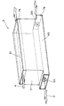
次に、本実施形態に係る電池モジュールBの冷却構造について説明する。図4に示すように、放熱板41は、アルミニウム素材にニッケルメッキを施したものであり、積層方向Xに直交する方向に延びる直線状の貫通孔として形成された、冷却用の空気を通すための複数の通風孔41aを有している。図2に示すように、この放熱板41が、電池モジュールBにおいて、隣接する単位セルCの一方の第1蓋部材23と他方の第2蓋部材25との間に介在するように積層されている。
Next, the cooling structure of the battery module B according to this embodiment will be described. As shown in FIG. 4, the
また、図5に示すように、電池モジュールBのハウジング7の上部5aおよび底部5bの内方には、冷却媒体となる空気を流通させるための各流通空間61,63が形成されており、底部5bの前端壁および後端壁に、それぞれ、電池積層体1を強制的に冷却するための吸気ファン65が設置されている。各吸気ファン65から底部5bの流通空間63に導入された空気Aは、上部5aの流通空間61を通って前後の開口から外部に排出されるまでの途中で、図4に示す放熱板41の通風孔41aに入り込み、放熱板41を介して単位電池Cを冷却する。このようにして、通風孔41aが単位電池Cを冷却するための冷却媒体通路として機能する。なお、本実施形態では、放熱板41を、単位電池C2つに1つの割合で介在させているが、放熱板41を介在させる位置や数は適宜変更してよい。また、冷媒としては、空気Aの他に、一般的に用いられているもの、例えば油を使用してもよい。
Further, as shown in FIG. 5,
放熱板41は、隣接する単位電池Cの一方の正極集電体である第1蓋部材23と、他方の負極集電体である第2蓋部材25との間に介在するので、これら2つの単位電池Cを電気的に接続するべく、電気伝導性を有することが必要である。この点において、アルミニウムは電気抵抗が比較的低く、熱伝導率が比較的大きいので、放熱板41を形成する素材として好ましい特性を有している。しかしながら、アルミニウムは酸化しやすく、接触抵抗も大きいので、アルミニウム板にニッケルメッキを施すことにより、接触抵抗の低減を図っている。
Since the
次に、本発明の一実施形態に係る負極放電リザーブの低減方法について説明する。図6は、本発明に係る電池モジュールの負極放電リザーブ低減方法を含む、電池モジュールBの生産過程を示すフロー図である。図6に示すように、電池モジュールBは組み立てられた後に、初期活性化工程に投入され、所定の条件で数サイクルの充放電が行われる。その後、初期活性化のための充放電を終えて放電状態に置かれた電池モジュールBの各単位電池Cの内部に、酸素が供給され、この酸素が負極内の放電リザーブである水素と反応してH2Oを生成することにより、放電リザーブが低減される。この際に供給する酸素の量は、電池モジュールBの生産過程とは別に行う放電リザーブ量の測定結果に基づいて決定される。また、酸素が電池モジュールBに供給されている間は、並行して、電池モジュールBの電池積層体1を構成する単位電池Cの冷却が行われる。これら放電リザーブ量測定、酸素供給、電池モジュール冷却で構成される放電リザーブ低減が行われた後に、電池モジュールBは出荷される。
Next, a method for reducing the negative electrode discharge reserve according to an embodiment of the present invention will be described. FIG. 6 is a flowchart showing the production process of the battery module B including the method for reducing negative discharge reserve of the battery module according to the present invention. As shown in FIG. 6, after the battery module B is assembled, it is put into an initial activation process, and charging and discharging are performed for several cycles under predetermined conditions. Thereafter, oxygen is supplied into each unit cell C of the battery module B which has been charged and discharged for initial activation and placed in a discharged state, and this oxygen reacts with hydrogen which is a discharge reserve in the negative electrode. By generating H 2 O, the discharge reserve is reduced. The amount of oxygen supplied at this time is determined based on the measurement result of the discharge reserve amount that is performed separately from the production process of the battery module B. In addition, while oxygen is supplied to the battery module B, the unit battery C constituting the
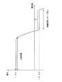
本実施形態における、負極放電リザーブの量の測定は、例えば、以下のようにして行う。まず、実際に酸素供給が行われる電池モジュールBと同じ仕様の電池モジュールを、放電リザーブ量測定用に用意する。この電池モジュールについて、実際の生産工程と同じ条件で初期活性化のための充放電を行って放電状態にした後に、低率の定電流でさらに放電を行う。このときの放電終止電圧は、単位電池C当たり−0.2Vよりも低い値、例えば−0.5Vに設定する。このような条件で放電を行い、電池電圧−放電容量特性を測定すると、図7に示すように、過放電領域の−0.2V付近に平坦な電圧領域Pが観測される。この平坦領域Pの放電量x(Ah)が放電リザーブとして蓄えられている水素の量を表している。すなわち、このとき負極では、下記の一電子反応(6)
MH → M + H+ + e− (6)
によって、負極の水素が酸化されている。電子1モルの電気量は96500クーロン、また1Ahは3600クーロンであるので、xAhの放電量は、水素原子3600x/96500モルに相当する。
The measurement of the amount of negative electrode discharge reserve in this embodiment is performed as follows, for example. First, a battery module having the same specifications as the battery module B to which oxygen is actually supplied is prepared for measuring the discharge reserve amount. The battery module is charged and discharged for initial activation under the same conditions as the actual production process to be in a discharged state, and then further discharged at a low constant current. The discharge end voltage at this time is set to a value lower than −0.2 V per unit battery C, for example, −0.5 V. When discharging is performed under such conditions and the battery voltage-discharge capacity characteristics are measured, a flat voltage region P is observed in the vicinity of -0.2 V in the overdischarge region as shown in FIG. The discharge amount x (Ah) in the flat region P represents the amount of hydrogen stored as the discharge reserve. That is, at this time, in the negative electrode, the following one-electron reaction (6)
MH → M + H + + e - (6)
As a result, hydrogen of the negative electrode is oxidized. Since the electric quantity of 1 mol of electrons is 96500 coulombs and 1Ah is 3600 coulombs, the discharge quantity of xAh corresponds to 3600 x / 96500 mols of hydrogen atoms.
1モルの水素原子と反応してH2Oを生成するために必要な酸素ガス(O2)は、1/4モルであるので、結局、上記の測定から得られた負極放電リザーブ量に相当する酸素ガスの量は、3600x/(96500×4)=約0.0093xモルとなる。 Since the oxygen gas (O 2 ) required to react with 1 mol of hydrogen atoms to generate H 2 O is ¼ mol, it corresponds to the negative electrode discharge reserve amount obtained from the above measurement. The amount of oxygen gas to be used is 3600 × / (96500 × 4) = about 0.0093 × mol.
電池積層体1を構成する各単位電池C内への酸素ガスの供給は、例えば、以下のようにして行う。まず、図2に示すガス供給系統39の流路開閉機構55を酸素タンク57側に切り替えた状態で、流量調整弁53を所定の値に設定し、酸素タンク57から連通チューブ51および連通口37を介して各単位電池C内に酸素ガスを供給し、この酸素ガスを、負極に蓄積された水素と反応させてH2Oを生成する。酸素ガスの供給量の制御は、例えば、上述の負極放電リザーブ量の測定値を基にして、予め供給すべき酸素ガス流量を決めておき、その所定のガス流量だけ供給されるように調節することができる。あるいは、電池モジュールB全体もしくは各単位電池Cの電圧を監視しながら酸素ガス供給を行い、所定の電圧値まで下降した時点で供給を停止するようにしてもよい。
The supply of oxygen gas into each unit battery C constituting the
上記実施形態に係る電池モジュールBの負極放電リザーブ低減方法によれば、以下の効果が得られる。 According to the negative electrode discharge reserve reducing method of the battery module B according to the embodiment, the following effects are obtained.
上記で説明した本実施形態に係る電池モジュールの負極放電リザーブ低減方法においては、ニッケル水素二次電池として構成された単位電池Cを有する電池モジュールBが、単位電池Cの内部に連通する酸素供給源5を備えており、電池モジュールBの初期活性化の後に、単位電池Cの内部に酸素ガスを供給して、負極に吸蔵された放電リザーブである水素と反応させる。したがって、初期活性化によって負極に蓄積された水素が、酸素供給源から供給する酸素と反応してH2Oとなって、負極の放電リザーブが低減するので、電解液のドライアウトを防止して、電池性能、特には充放電サイクル寿命の劣化を防止することができる。また、初期段階での負極の放電リザーブを低減できることから、予め設定する充電リザーブの量、すなわち余分に充填する負極活物質の量をも低減することが可能となるので、電池全体の充放電容量を増大させることができる。 In the method for reducing negative discharge reserve of the battery module according to the present embodiment described above, the oxygen supply source in which the battery module B having the unit battery C configured as a nickel hydride secondary battery communicates with the inside of the unit battery C. 5, after the initial activation of the battery module B, oxygen gas is supplied into the unit battery C and reacted with hydrogen, which is a discharge reserve occluded in the negative electrode. Therefore, the hydrogen accumulated in the negative electrode due to the initial activation reacts with the oxygen supplied from the oxygen supply source to become H 2 O and the discharge reserve of the negative electrode is reduced. It is possible to prevent deterioration of battery performance, particularly charge / discharge cycle life. In addition, since the discharge reserve of the negative electrode in the initial stage can be reduced, it is possible to reduce the amount of charge reserve set in advance, that is, the amount of the negative electrode active material to be additionally filled, so that the charge / discharge capacity of the entire battery can be reduced. Can be increased.
また、本実施形態に係る負極放電リザーブ低減方法においては、酸素供給源5から単位電池Cの内部への酸素の供給量を、予め測定した負極放電リザーブ量に基づいて決定し、制御を行っているので、適切な量の酸素を供給して効果的に放電リザーブを低減することができる。
Further, in the negative electrode discharge reserve reducing method according to the present embodiment, the supply amount of oxygen from the
さらには、電池モジュールBに、電池積層体1を構成する各単位電池Cを冷却する冷却構造、つまり通風孔41aを有する放熱板41を設けているので、放電リザーブである水素が酸素と反応してH2Oを生成する発熱反応に起因する電池温度上昇を防止することができる。一般的に、電池温度の上昇は、電池を構成する材料の劣化を招き、電池性能の低下をもたらすが、電池モジュールBにこのような冷却構造を設けることにより、簡単な構造で、電池積層体1の表面のみならず単位電池Cの積層面をも効果的に冷却して、電池モジュールBの性能劣化を防止することができる。
Furthermore, since the battery module B is provided with a cooling structure for cooling the unit cells C constituting the
また、本実施形態に係る電池モジュールBは、上述の方法によって負極放電リザーブを低減することが可能となるので、予め正極活物質よりも余分に充填しておく負極活物質の充電リザーブ相当分を低減することができ、正極活物質の充填量に対する負極活物質の充填量の比を、容量換算で100〜400%の範囲内に設定している。したがって、電池モジュールBの充放電容量を増加させることが可能となる。 In addition, since the battery module B according to the present embodiment can reduce the negative electrode discharge reserve by the above-described method, an amount equivalent to the charge reserve of the negative electrode active material that is previously filled in excess of the positive electrode active material is provided. The ratio of the filling amount of the negative electrode active material to the filling amount of the positive electrode active material can be reduced, and is set within a range of 100 to 400% in terms of capacity. Therefore, the charge / discharge capacity of the battery module B can be increased.
以上のとおり、図面を参照しながら本発明の好適な実施形態を説明したが、本発明の趣旨を逸脱しない範囲内で、種々の追加、変更または削除が可能である。したがって、そのようなものも本発明の範囲内に含まれる。 As described above, the preferred embodiments of the present invention have been described with reference to the drawings, but various additions, modifications, or deletions can be made without departing from the spirit of the present invention. Therefore, such a thing is also included in the scope of the present invention.
1 電池積層体
3 連通部材
5 酸素供給源
27 ガス導入口
51 連結チューブ(連通部材)
52 導出チューブ(連通部材)
C 単位電池
B 電池モジュール
DESCRIPTION OF
52 Lead tube (communication member)
C Unit battery B Battery module
Claims (5)
前記単位電池の初期活性化充放電の後に、前記酸素供給源から前記単位電池の内部に酸素を供給して、負極に吸蔵された放電リザーブである水素と反応させることを含む電池モジュールの負極放電リザーブ低減方法。 A method for reducing negative discharge reserve of a battery module comprising a unit battery configured as a nickel metal hydride secondary battery and an oxygen supply source communicating with the inside of the unit battery,
After the initial activation charge / discharge of the unit battery, the negative discharge of the battery module includes supplying oxygen from the oxygen supply source to the inside of the unit battery and reacting with hydrogen which is a discharge reserve stored in the negative electrode Reserve reduction method.
Priority Applications (1)
| Application Number | Priority Date | Filing Date | Title |
|---|---|---|---|
| JP2008203027A JP2010040375A (en) | 2008-08-06 | 2008-08-06 | Anode discharge reserve reduction method of battery module |
Applications Claiming Priority (1)
| Application Number | Priority Date | Filing Date | Title |
|---|---|---|---|
| JP2008203027A JP2010040375A (en) | 2008-08-06 | 2008-08-06 | Anode discharge reserve reduction method of battery module |
Publications (2)
| Publication Number | Publication Date |
|---|---|
| JP2010040375A true JP2010040375A (en) | 2010-02-18 |
| JP2010040375A5 JP2010040375A5 (en) | 2011-08-11 |
Family
ID=42012701
Family Applications (1)
| Application Number | Title | Priority Date | Filing Date |
|---|---|---|---|
| JP2008203027A Pending JP2010040375A (en) | 2008-08-06 | 2008-08-06 | Anode discharge reserve reduction method of battery module |
Country Status (1)
| Country | Link |
|---|---|
| JP (1) | JP2010040375A (en) |
Cited By (2)
| Publication number | Priority date | Publication date | Assignee | Title |
|---|---|---|---|---|
| JP2013122891A (en) * | 2011-12-12 | 2013-06-20 | Kawasaki Heavy Ind Ltd | Secondary battery, secondary battery system, and discharge reserve reduction method of secondary battery and secondary battery system |
| JP2020061223A (en) * | 2018-10-05 | 2020-04-16 | 株式会社豊田自動織機 | Method of manufacturing nickel metal hydride storage battery |
Citations (5)
| Publication number | Priority date | Publication date | Assignee | Title |
|---|---|---|---|---|
| JPH01283774A (en) * | 1988-05-10 | 1989-11-15 | Toshiba Corp | Nickel oxide and hydrogen secondary battery |
| JPH05251108A (en) * | 1992-03-04 | 1993-09-28 | Sanyo Electric Co Ltd | Sealed type metal-hydrogen alkali storage battery |
| JPH06150963A (en) * | 1992-11-10 | 1994-05-31 | Matsushita Electric Ind Co Ltd | Storage battery system |
| JP2006260967A (en) * | 2005-03-17 | 2006-09-28 | Toyota Motor Corp | Battery module |
| JP2008171628A (en) * | 2007-01-10 | 2008-07-24 | Furukawa Sky Kk | Partitioning plate for heat dissipation of battery case |
-
2008
- 2008-08-06 JP JP2008203027A patent/JP2010040375A/en active Pending
Patent Citations (5)
| Publication number | Priority date | Publication date | Assignee | Title |
|---|---|---|---|---|
| JPH01283774A (en) * | 1988-05-10 | 1989-11-15 | Toshiba Corp | Nickel oxide and hydrogen secondary battery |
| JPH05251108A (en) * | 1992-03-04 | 1993-09-28 | Sanyo Electric Co Ltd | Sealed type metal-hydrogen alkali storage battery |
| JPH06150963A (en) * | 1992-11-10 | 1994-05-31 | Matsushita Electric Ind Co Ltd | Storage battery system |
| JP2006260967A (en) * | 2005-03-17 | 2006-09-28 | Toyota Motor Corp | Battery module |
| JP2008171628A (en) * | 2007-01-10 | 2008-07-24 | Furukawa Sky Kk | Partitioning plate for heat dissipation of battery case |
Cited By (3)
| Publication number | Priority date | Publication date | Assignee | Title |
|---|---|---|---|---|
| JP2013122891A (en) * | 2011-12-12 | 2013-06-20 | Kawasaki Heavy Ind Ltd | Secondary battery, secondary battery system, and discharge reserve reduction method of secondary battery and secondary battery system |
| JP2020061223A (en) * | 2018-10-05 | 2020-04-16 | 株式会社豊田自動織機 | Method of manufacturing nickel metal hydride storage battery |
| JP7095539B2 (en) | 2018-10-05 | 2022-07-05 | 株式会社豊田自動織機 | Manufacturing method of nickel-metal hydride storage battery |
Similar Documents
| Publication | Publication Date | Title |
|---|---|---|
| JP5308729B2 (en) | Fuel cell storage battery and battery module using the same | |
| US9590262B2 (en) | Reversible fuel cell and reversible fuel cell system | |
| JP3365577B2 (en) | Single-cell and unit cells of sealed nickel-hydrogen storage batteries | |
| US20110195321A1 (en) | Rechargeable metal-air battery | |
| EP2976803B1 (en) | Metal/oxygen battery with oxygen pressure management | |
| CN108432033B (en) | Battery module, battery pack including the same, and vehicle | |
| WO2014103943A1 (en) | Zinc hybrid battery | |
| CN112072008B (en) | Battery pack and vehicle | |
| JP2009266773A (en) | Battery device | |
| KR20180081851A (en) | Metal/oxygen battery with multistage oxygen compression | |
| JP5937341B2 (en) | Secondary battery, secondary battery system, secondary battery and method for reducing discharge reserve of secondary battery system | |
| JP2010040324A (en) | Estimation method of state of charge of battery module, and charging method using this | |
| JP5325480B2 (en) | Secondary battery, battery module and charging method thereof | |
| JP2010040375A (en) | Anode discharge reserve reduction method of battery module | |
| JP6178870B2 (en) | Metal oxygen battery with multistage oxygen compressor | |
| JP5514594B2 (en) | Nitrogen battery float charging system | |
| JP5426847B2 (en) | Method for charging nickel-metal hydride battery stack and its charge control system | |
| JP2009016235A (en) | Power storage device | |
| JP5926571B2 (en) | Battery module | |
| JP5502307B2 (en) | Alkaline storage battery and method for reducing discharge reserve of alkaline storage battery | |
| CN216597727U (en) | Air-cooled battery pack | |
| WO2022208530A1 (en) | An energy storage cell | |
| CN116154358A (en) | Battery and electric equipment | |
| JP2006127902A (en) | Cooling structure of battery |
Legal Events
| Date | Code | Title | Description |
|---|---|---|---|
| A521 | Request for written amendment filed |
Free format text: JAPANESE INTERMEDIATE CODE: A523 Effective date: 20110628 |
|
| A621 | Written request for application examination |
Free format text: JAPANESE INTERMEDIATE CODE: A621 Effective date: 20110628 |
|
| A131 | Notification of reasons for refusal |
Free format text: JAPANESE INTERMEDIATE CODE: A131 Effective date: 20130423 |
|
| A02 | Decision of refusal |
Free format text: JAPANESE INTERMEDIATE CODE: A02 Effective date: 20130820 |