JP2010040351A - Light guide plate and planar light-emitting device - Google Patents
Light guide plate and planar light-emitting device Download PDFInfo
- Publication number
- JP2010040351A JP2010040351A JP2008202670A JP2008202670A JP2010040351A JP 2010040351 A JP2010040351 A JP 2010040351A JP 2008202670 A JP2008202670 A JP 2008202670A JP 2008202670 A JP2008202670 A JP 2008202670A JP 2010040351 A JP2010040351 A JP 2010040351A
- Authority
- JP
- Japan
- Prior art keywords
- light
- light guide
- guide plate
- protrusion
- protrusions
- Prior art date
- Legal status (The legal status is an assumption and is not a legal conclusion. Google has not performed a legal analysis and makes no representation as to the accuracy of the status listed.)
- Granted
Links
Images


Landscapes
- Planar Illumination Modules (AREA)
Abstract
Description
本発明は、導光体の内部をその端面から入射した光源からの光を導光し、射出面から射出する導光板、及びその導光板を有する面発光装置に関するものである。 The present invention relates to a light guide plate that guides light from a light source incident from an end surface of a light guide body and emits the light from an exit surface, and a surface light emitting device having the light guide plate.
表示器の液晶パネルの背面には、面光源装置をバックライトとして配置したものがある。バックライトは、エッジライト方式と直下方式とに大別される。エッジライト方式は、表示器の背後に設けられた導光板の端部の発光体(CCT,LED等)からの光線を導光板で所定領域に透過、反射させる方式である。直下方式は、表示器の背後にLED等の光源を配置し、拡散板等で拡散した光を透過させる方式である。 Some display devices have a surface light source device arranged as a backlight on the back side of the liquid crystal panel. The backlight is roughly classified into an edge light system and a direct system. The edge light system is a system in which light from a light emitter (CCT, LED, etc.) at the end of a light guide plate provided behind a display is transmitted and reflected by a light guide plate to a predetermined area. The direct method is a method in which a light source such as an LED is disposed behind the display and light diffused by a diffusion plate or the like is transmitted.
特許文献1には、エッジライト方式において点状に配置した光源を使用した場合でも、プリズムシート等の拡散板を用いずに、入射光を効率良く導光板の正面に射出するための構造が記載されている。詳細には、導光板において、点状光源から導光板に入射した光を、射出面に向けて反射させる溝が複数並んでおり、射出面にはレンズ状の突条が溝の延びる方向と直交する方向に延びるように複数設けられている。そして、レンズ状の突条により、拡散板を用いずに入射光を効率良く導光板の正面に射出すると共に、輝線の発生を抑制している。
しかしながら、上述した特許文献1に示す導光板では、光源近くで多くの光がその正面側から射出され、また、光源から離れたところでは正面側から射出される光が光源近くに対して少なくなってしまうという問題があった。そのため、導光板の正面から射出される光の光量を均一とすることができず、その輝度差が視認者から斑となって視認されてしまうという問題となっていた。つまり、上記特許文献1の導光板を広範囲に用いると、光源からの入射光を効率良く導光板の正面から射出できないため、拡散板を用いたり、小型の導光板を複数用いる必要があった。
However, in the light guide plate shown in
よって本発明は、上述した問題点に鑑み、従来の拡散板を用いることなく、広範囲にわたる射出面の明暗を抑制して均一な照明を可能とする導光板及び面発光装置を提供することを課題としている。 Therefore, in view of the above-described problems, the present invention has an object to provide a light guide plate and a surface light emitting device capable of uniform illumination by suppressing the brightness of the exit surface over a wide range without using a conventional diffusion plate. It is said.
上記課題を解決するため本発明によりなされた請求項1記載の導光板は、光源からの光が端面から入射される導光板本体と、前記導光板本体における前記光の導光方向に沿って複数並べられるように前記導光板本体の射出側に突出して形成され且つ前記導光板本体内を導光した光を射出する複数の突条部と、前記導光板本体の射出側に対向する対向面に前記導光方向と交わるように複数並んだ溝状に形成され且つ前記光を突条部に向けて反射する複数の反射部と、を有し、照明対象物の背後に設けられる導光板において、前記突条部が、前記端面の近傍の近傍領域に形成された第1突条部と、前記近傍領域よりも前記端面から離れた遠方領域に形成された第2突条部と、を有し、前記第2突条部に相対向する前記反射部の数を前記第1突条部に相対向する前記反射部の数よりも多くして、前記第2突条部から射出される光量を前記第1突条部から射出される光量よりも多くするようにしたことを特徴とする。
The light guide plate according to
上記請求項1に記載した本発明の導光板によれば、導光板本体の端面から入射した光は、導光板本体内を導光方向に導光されると、複数の反射部で突条部に向かって反射され、突条部から導光体の外部に向かって射出される。そのとき、導光板本体の遠方領域では第2突条部と相対向する反射部の数が、近傍領域の第1突条部と相対向する反射部の数よりも多いことから、各反射部で反射して第2突条部に向かう光量は第1突条部に向かう光量よりも多くすることができる。よって、光源に近い導光体本体の近傍領域から射出する光量は、光源から離れた遠方領域から射出する光量よりも少なくできる。
According to the light guide plate of the present invention described in
請求項2記載の発明は、請求項1に記載の導光板において、前記第1突条部が、前記第2突条部の大きさよりも小さく形成され、そして、前記複数の反射部が、前記導光板本体の対向面に等間隔で形成されたことを特徴とする。 According to a second aspect of the present invention, in the light guide plate according to the first aspect, the first ridge is formed smaller than the size of the second ridge, and the plurality of reflection portions are The light guide plate main body is formed at equal intervals on the opposing surface.
上記請求項2に記載した本発明の導光板によれば、第1突条部を第2突条部の大きさよりも小さく形成し、複数の反射部を等間隔で形成しているので、第2突条部には第1突条部よりも多くの反射部を対向させることができる。 According to the light guide plate of the present invention described in claim 2, the first protrusion is formed smaller than the second protrusion and the plurality of reflection parts are formed at equal intervals. More reflective parts can be made to oppose the 2 protrusion part than a 1st protrusion part.
請求項3記載の発明は、請求項1又は2に記載の導光板において、前記第1突条部及び前記第2突条部の相対的な大きさが、前記導光板本体の射出側における前記近傍領域及び前記遠方領域の照度が略同一となるように設定されていることを特徴とする。 According to a third aspect of the present invention, in the light guide plate according to the first or second aspect, the relative size of the first ridge portion and the second ridge portion is the light emission side of the light guide plate main body. The illuminance in the vicinity area and the far area is set to be substantially the same.
上記請求項3に記載した本発明の導光板によれば、第1突条部と第2突条部との相対的な大きさを、導光板本体の射出側における近傍領域と遠方領域の照度が略均一となるように設定しているため、導光板本体の近傍領域及び遠方領域から外部に射出する光量を均一にできる。 According to the light guide plate of the present invention described in claim 3 above, the relative sizes of the first protrusion and the second protrusion are determined based on the illuminance in the vicinity region and the distant region on the exit side of the light guide plate body. Is set to be substantially uniform, the amount of light emitted to the outside from the vicinity region and the far region of the light guide plate body can be made uniform.
上記課題を解決するため本発明によりなされた請求項4記載の面発光装置は、請求項1〜3の何れか1項に記載の導光板と、前記導光板の端面に配置された光源と、を有することを特徴とする。
The surface light-emitting device according to claim 4 made according to the present invention in order to solve the above-described problem, the light guide plate according to any one of
上記請求項4に記載した本発明の面発光装置によれば、光源が発した光は端面から導光板内に入射し、複数の反射部の各々で射出側に反射されて導光板の外部に射出される。そのとき、導光板の近傍領域及び遠方領域からは均一な光量で光を射出させることができる。 According to the surface light-emitting device of the present invention described in claim 4, the light emitted from the light source enters the light guide plate from the end surface, is reflected to the exit side by each of the plurality of reflecting portions, and is outside the light guide plate. It is injected. At that time, light can be emitted with a uniform amount of light from the vicinity region and the far region of the light guide plate.
以上説明したように請求項1に記載した本発明の導光板によれば、導光板本体の遠方領域で第2突条部と相対向する反射部の数を、近傍領域の第1突条部と相対向する反射部の数よりも多くしたことから、光源に近い導光体本体の近傍領域から射出する光量は、光源から離れた遠方領域から射出する光量よりも少なくできるため、導光板の射出面から射出する光量を均一とすることができる。従って、従来のように拡散板を用いることなく、近傍領域と遠方領域を含む広範囲にわたる射出面の明暗を抑制して斑なく均一な照明を行うことができる。
As described above, according to the light guide plate of the present invention described in
請求項2に記載した本発明の導光板によれば、請求項1に記載の発明の効果に加え、第1突条部を第2突条部の大きさよりも小さく形成し、複数の反射部を等間隔で形成しているので、第2突条部には第1突条部よりも多くの反射部を対向させることができるため、第2突条部から射出する光量を第1突条部よりも多くすることができる。また、第1突条部及び第2突条部の大きさによって射出させる光量を調整することができる。
According to the light guide plate of the present invention described in claim 2, in addition to the effect of the invention described in
請求項3に記載した本発明の導光板によれば、請求項1又は2に記載の発明の効果に加え、第1突条部と第2突条部との相対的な大きさを、導光板本体の射出側における近傍領域と遠方領域の照度が略均一となるように設定するようにしたことから、導光板本体の近傍領域及び遠方領域から外部に射出する光量をより均一にできる。
According to the light guide plate of the present invention described in claim 3, in addition to the effect of the invention described in
以上説明したように請求項4に記載した本発明の面発光装置によれば、拡散板を用いることなく、近傍領域と遠方領域を含む広範囲にわたる射出面の明暗を抑制して斑なく均一な照明できる導光板を有するようにしたことから、点光源を用いることができるため、装置のコストダウンを図ることができる。また、導光板によって広範囲を照明できるため、表示器等の大型化に貢献することができる。 As described above, according to the surface light emitting device of the present invention described in claim 4, uniform illumination without unevenness is achieved without using a diffuser plate and suppressing the brightness of the exit surface over a wide range including the near and far regions. Since a light guide plate that can be used is used, a point light source can be used, so that the cost of the apparatus can be reduced. In addition, since a wide range can be illuminated by the light guide plate, it can contribute to an increase in the size of a display device or the like.
以下、本発明に係る導光板及び面発光装置の一実施形態を、図1〜図5の図面を参照して以下に説明する。 Hereinafter, an embodiment of a light guide plate and a surface light emitting device according to the present invention will be described below with reference to the drawings of FIGS.
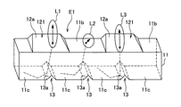
図1において、面発光装置1は、導光板10と、光源20とを有して構成している。面発光装置1は、例えば車両用計器の文字板、液晶パネル、等の各種表示器の背後に設けられる。そして、本実施形態では、面発光装置1を略円形状の文字板(図示せず)の背後に設けて、バックライトとして用いられる場合について説明する。
In FIG. 1, the surface
なお、文字板は、公知であるように、透光性部材によって板状に形成されており、その表面は目盛や数字等の指標以外の部分が非透光性部材で覆われている。そして、面発光装置1から射出した光を前記文字板の裏面から透過させることで、該透過光によって指標を発光させる。
As is well known, the dial plate is formed in a plate shape by a translucent member, and the surface of the dial plate is covered with a non-translucent member other than indices such as scales and numerals. Then, by transmitting the light emitted from the surface
導光板10は、導光板本体11と、複数の突条部12と、複数の反射部13と、を有して構成している。
The
導光板本体11は、例えば透光性のアクリル樹脂、ポリカーボネート樹脂、等によって略板状に形成されている。導光板本体11の外形は、前記文字板と相似形の略リング状に形成されており、照明対象物の外形と相似形に形成される。導光板本体11は、両側の端面11aに光源20が対向するように、前記文字板の背後に配置される。導光板本体11は、その光源20から内部に入射した光を導光方向Xに向かって導光するものである。
The light
本実施形態では、導光板本体11において、対象中心線Cを中心に対象に形成されている。導光板本体11は、端面11aから所定の距離だけ離れた領域までが、端面11aの近傍の近傍領域E1であり、該近傍領域E1から対象中心線Cまでの領域が、端面11aから近傍領域E1よりも離れた遠方領域E2とそれぞれ設定している。なお、近傍領域E1と遠方領域E2の設定については、例えば光源20の輝度や、導光板本体11の寸法、外形等に応じて適宜設定することができる。
In the present embodiment, the light guide plate
複数の突条部12の各々は、導光板本体11における光の導光方向Xに沿って複数並べられるように導光板本体11の射出面11b側に突出したレンズ状に形成されている。即ち、複数の突条部12が、導光方向Xに延びる円弧状の列として射出面11bに形成されている。そして、本実施形態では、図1に示すように、複数の突条部12が導光方向Xに沿って6列形成する場合について説明するが、本発明はこれに限定するものではなく、射出面11bから射出する光量等を考慮して設計することができる。
Each of the plurality of
突条部12は、図2及び図3に示すように、導光板本体11内を導光した光を射出するように、導光方向Xと交わる方向の断面が略三角形に形成されている。突条部12は、射出面12aを有し、この射出面12aは後述する反射部13で反射した光が透過するように、導光板本体11の射出面11bから突出する傾斜面となっている。即ち、射出面12aは、反射光が射出面11bで内面反射することを低下させている。よって、射出面11bから外部に射出する光の光量は、その周りの射出面11bから外部に射出する光の光量よりも多くなっている。なお、突条部12の断面形状は、本実施形態の略三角形に限定するものではなく、例えば、円弧、半円、四角、等の各種断面形状とすることができる。
As shown in FIGS. 2 and 3, the
突条部12は、導光体本体11の端面11aの近傍の近傍領域E1に形成された複数の第1突条部121と、前記端面11aから近傍領域E1よりも離れた遠方領域E2に形成された複数の第2突条部122と、を有して構成している。そして、第1突条部121が、第2突条部122の大きさよりも小さく形成されている。即ち、第1突条部121及び第2突条部122の相対的な大きさが、導光板本体11の射出面11b側における近傍領域E1及び遠方領域E2の照度が略同一となるように設定されている。
The
なお、本実施形態では、近傍領域E1において複数の第1突条部121の各々は同一の大きさであり、また、遠方領域E2において複数の第2突条部122の各々も同一の大きさとなっている。しかしながら、各領域において射出する光量を変化させる必要がある場合等は、例えば、光源20に近い方から徐々に大きさを大きくする、複数種類の大きさを任意のパターンで配置するなど種々異なる実施形態とすることができる。なお、その実施形態でも、第1突条部121の大きさは第2突条部122よりも小さく形成する。
In the present embodiment, each of the plurality of
複数の反射部13の各々は、図2,4,5に示すように、導光板本体11の射出面11b側に対向する対向面(底面)11cに導光方向Xと交わるように複数並んだ溝状に形成されており、導光板本体11の内部を導光した光を突条部12に向けて反射する反射面13aを有している。反射部13は、断面が略V字状の溝として導光板本体11の対向面11cに形成されている。複数の反射部13は、導光方向Xに向かって対向面11cに等間隔で形成されており、その間隔は突条部12に向かって反射させる反射光の光量等に応じて任意に設計される。
As shown in FIGS. 2, 4, and 5, each of the plurality of reflecting
なお、本実施形態では、複数の反射部13を等間隔で配置した場合について説明するが、本発明はこれに限定するものではなく、例えば、近傍領域E1では複数の反射部13の間隔を狭くし、遠方領域E2では間隔を広くするなど種々異なる実施形態とすることができる。
In addition, although this embodiment demonstrates the case where the some
上述した構成の導光板10は、図4,5に示すように、複数の反射部13を等間隔で形成しているが、第1突条部121の大きさ(導光方向Xにおける長さ)は第2突条部122よりも小さく形成していることから、図4に示すように、第1突条部121には1つの反射部13が対向し、また、図5に示すように、第2突条部122には3つの反射部13が対向している。よって、第1突条部121に向けて反射される光量は、第2突条部122に向けて反射される光量よりも少なくなっている。
As shown in FIGS. 4 and 5, the
光源20は、LED(発光ダイオード)、バルブ等が任意に用いられる。光源20は、プリント基板30に実装されており、そのプリント基板30によって導光板本体11の端面11aと対向するように位置付けられる。光源20は、プリント基板30に実装された制御部(図示せず)によって点灯/消灯が制御される。
As the
次に、上述した構成の面発光装置1の本発明に係る動作(作用)の一例を図4,5の図面等を参照して以下に説明する。
Next, an example of the operation (action) according to the present invention of the surface
面発光装置1は、起動されると光源20を点灯させる。すると、光源20が発した光は導光板10の端面11aから導光板本体11内に入射され、導光板本体11内を導光方向Xに向かって導光される。まず、導光板本体11の近傍領域E1では、図4に示すように、光L1,3は、反射部13の反射面13aで第1突出部121に向かって反射され、第1突出部121の射出面12aから導光体10の外部に向けて射出される。また、光L2は、反射部13の反射面13aで導光体本体11の射出面11bに向かって反射され、その一部は射出面11bから導光体10の外部に向けて射出され、その他は射出面11bで内面反射されて導光板本体11内を導光される。
When activated, the surface
また、導光板本体11の遠方領域E2では、図5に示すように、光L4〜L6は、反射部13の反射面13aで第2突出部122に向かって反射され、第2突出部122の射出面12aから導光体10の外部に向けて射出される。よって、第1突条部121が短い突条に形成されていることから、短い突条が全て繋がった第2突条部122と比べて、導光板10の射出面11b側に射出する光は減少する。
Further, in the far region E2 of the light
これにより、明るくなりやすい光源20近くの導光板10の正面に射出する光を減少させ、光源20から離れた射出面11bと同等の明るさに抑制することができる。また、突条部12の長さを変えることで、射出する光の明暗を光源20から離れたところの明るさに合わせるように制御することができるため、導光板10から射出される光を均一にすることができる。よって、面発光装置1の照明対象物である前記文字板は、面発光装置1が射出した光を透過させることで、該透過光によって指標を発光させる。
Thereby, the light emitted to the front surface of the
以上説明した導光板10によれば、導光板本体11の遠方領域E2で第2突条部122と相対向する反射部13の数を、近傍領域E1の第1突条部121と相対向する反射部13の数よりも多くしたことから、光源20に近い導光体本体11の近傍領域E1から射出する光量は、光源20から離れた遠方領域E2から射出する光量よりも少なくできるため、導光板10の射出面11bから射出する光量を均一とすることができる。従って、従来のように拡散板を用いることなく、近傍領域E1と遠方領域E2を含む広範囲にわたる射出面11bの明暗を抑制して斑なく均一な照明を行うことができる。
According to the
また、第1突条部121を第2突条部122の大きさよりも小さく形成し、複数の反射部13を等間隔で形成しているので、第2突条部122には第1突条部121よりも多くの反射部13を対向させることができるため、第2突条部122から射出する光量を第1突条部121よりも多くすることができる。また、第1突条部121及び第2突条部122の大きさによって射出させる光量を調整することができる。
Moreover, since the
さらに、第1突条部121と第2突条部122との相対的な大きさを、導光板本体11の射出側における近傍領域E1と遠方領域E2の照度が略均一となるように設定するようにしたことから、導光板本体11の近傍領域E1及び遠方領域E2から外部に射出する光量をより均一にできる。
Furthermore, the relative sizes of the
また、面発光装置1によれば、従来の拡散板を用いることなく、近傍領域E1と遠方領域E2を含む広範囲にわたる射出面11bの明暗を抑制して斑なく均一な照明できる導光板10を有するようにしたことから、点光源を用いることができるため、装置のコストダウンを図ることができる。また、導光板10によって広範囲を照明できるため、表示器等の大型化に貢献することができる。
Moreover, according to the surface light-emitting
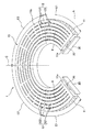
なお、上述した本実施形態では、図1に示すように、導光板10の近傍領域E1及び遠方領域E2の各々において、第1突条部121と第2突条部122を同一の大きさとした場合について説明したが、本発明はこれに限定するものではなく、例えば、図6に示すように、近傍領域E1から遠方領域E2にわたって光源20寄りから第1突条部121と第2突条部122を連続的に徐々に大きくなるように形成したり、遠方領域E2のみ第2突条部122を光源20寄りから徐々に大きく形成したり、光源20寄りから段階的に大きく形成する、など種々異なる実施形態とすることができる。
In the present embodiment described above, as shown in FIG. 1, the
また、上述した本実施形態では、導光板10を略リング状に形成した場合について説明したが、本発明はこれに限定するものではなく、例えば、正方形、長方形、扇形、等の各種形状とすることができる。その場合でも、光源20の近くを近傍領域E1、それよりも遠い領域を遠方領域E2と設定して、上述した突条部12と反射部3を配置することで、上述した作用効果を得ることができる。
Moreover, although this embodiment mentioned above demonstrated the case where the light-
なお、上述した本実施形態では、面発光装置1の照明対象物を前記文字板とした場合について説明したが、本発明はこれに限定するものではなく、例えば、液晶パネル、照明器具、等を照明対象物とするなど種々異なる実施形態とすることができる。
In addition, although this embodiment mentioned above demonstrated the case where the illumination target object of the
このように上述した実施例は本発明の代表的な形態を示したに過ぎず、本発明は、実施形態に限定されるものではない。即ち、本発明の骨子を逸脱しない範囲で種々変形して実施することができる。 As described above, the above-described embodiments are merely representative forms of the present invention, and the present invention is not limited to the embodiments. That is, various modifications can be made without departing from the scope of the present invention.
1 面発光装置
10 導光板
11 導光板本体
12 突条部
13 反射部
20 光源
121 第1突条部
122 第2突条部
E1 近傍領域
E2 遠方領域
X 導光方向
DESCRIPTION OF
Claims (4)
前記突条部が、前記端面の近傍の近傍領域に形成された第1突条部と、前記近傍領域よりも前記端面から離れた遠方領域に形成された第2突条部と、を有し、
前記第2突条部に相対向する前記反射部の数を前記第1突条部に相対向する前記反射部の数よりも多くして、前記第2突条部から射出される光量を前記第1突条部から射出される光量よりも多くするようにしたことを特徴とする導光板。 A light guide plate body in which light from a light source is incident from an end surface; and a plurality of light guide plates that are arranged along the light guide direction X of the light in the light guide plate body. A plurality of protrusions for emitting light guided in the light plate main body, and a plurality of grooves formed in a plurality of rows so as to cross the light guide direction on an opposing surface facing the light emission side of the light guide plate main body and the light A light guide plate provided behind the object to be illuminated,
The ridge has a first ridge formed in a vicinity region near the end surface, and a second ridge formed in a far region farther from the end surface than the vicinity region. ,
Increasing the number of the reflective portions opposed to the second ridge portion to be larger than the number of the reflective portions opposed to the first ridge portion, the amount of light emitted from the second ridge portion is A light guide plate characterized in that the amount of light emitted from the first protrusion is greater than the amount of light emitted from the first protrusion.
前記複数の反射部が、前記導光板本体の対向面に等間隔で形成されたことを特徴とする請求項1に記載の導光板。 The first protrusion is formed smaller than the size of the second protrusion, and
The light guide plate according to claim 1, wherein the plurality of reflecting portions are formed at equal intervals on a facing surface of the light guide plate main body.
Priority Applications (1)
| Application Number | Priority Date | Filing Date | Title |
|---|---|---|---|
| JP2008202670A JP5087493B2 (en) | 2008-08-06 | 2008-08-06 | Light guide plate and surface light emitting device |
Applications Claiming Priority (1)
| Application Number | Priority Date | Filing Date | Title |
|---|---|---|---|
| JP2008202670A JP5087493B2 (en) | 2008-08-06 | 2008-08-06 | Light guide plate and surface light emitting device |
Publications (2)
| Publication Number | Publication Date |
|---|---|
| JP2010040351A true JP2010040351A (en) | 2010-02-18 |
| JP5087493B2 JP5087493B2 (en) | 2012-12-05 |
Family
ID=42012680
Family Applications (1)
| Application Number | Title | Priority Date | Filing Date |
|---|---|---|---|
| JP2008202670A Expired - Fee Related JP5087493B2 (en) | 2008-08-06 | 2008-08-06 | Light guide plate and surface light emitting device |
Country Status (1)
| Country | Link |
|---|---|
| JP (1) | JP5087493B2 (en) |
Cited By (7)
| Publication number | Priority date | Publication date | Assignee | Title |
|---|---|---|---|---|
| US20110013416A1 (en) * | 2009-07-20 | 2011-01-20 | Kim Youngchan | Light guide plate and display apparatus having the same |
| JP2011040367A (en) * | 2009-07-16 | 2011-02-24 | Yazaki Corp | Light guide plate |
| JP2012185970A (en) * | 2011-03-04 | 2012-09-27 | Mitsubishi Electric Corp | Light guide body, light source for illumination, and lighting system |
| JP2012185969A (en) * | 2011-03-04 | 2012-09-27 | Mitsubishi Electric Corp | Light guide body, light source for illumination, and lighting system |
| WO2013094525A1 (en) * | 2011-12-21 | 2013-06-27 | シャープ株式会社 | Illumination device, backlight, liquid-crystal display, and television receiver |
| JP2014504787A (en) * | 2011-01-25 | 2014-02-24 | コーニンクレッカ フィリップス エヌ ヴェ | Lighting device |
| CN106122872A (en) * | 2016-08-22 | 2016-11-16 | 上海小糸车灯有限公司 | A kind of car light light conductor with multiple rows of shape photoconduction tooth |
Citations (2)
| Publication number | Priority date | Publication date | Assignee | Title |
|---|---|---|---|---|
| JPH10319242A (en) * | 1997-05-14 | 1998-12-04 | Sanyo Electric Co Ltd | Light guide plate |
| JP2006040710A (en) * | 2004-07-27 | 2006-02-09 | Nissen Chemitec Corp | Light guide plate and planar lighting system using it |
-
2008
- 2008-08-06 JP JP2008202670A patent/JP5087493B2/en not_active Expired - Fee Related
Patent Citations (2)
| Publication number | Priority date | Publication date | Assignee | Title |
|---|---|---|---|---|
| JPH10319242A (en) * | 1997-05-14 | 1998-12-04 | Sanyo Electric Co Ltd | Light guide plate |
| JP2006040710A (en) * | 2004-07-27 | 2006-02-09 | Nissen Chemitec Corp | Light guide plate and planar lighting system using it |
Cited By (9)
| Publication number | Priority date | Publication date | Assignee | Title |
|---|---|---|---|---|
| JP2011040367A (en) * | 2009-07-16 | 2011-02-24 | Yazaki Corp | Light guide plate |
| US20110013416A1 (en) * | 2009-07-20 | 2011-01-20 | Kim Youngchan | Light guide plate and display apparatus having the same |
| US8506152B2 (en) * | 2009-07-20 | 2013-08-13 | Samsung Display Co., Ltd. | Light guide plate and display apparatus having the same |
| JP2014504787A (en) * | 2011-01-25 | 2014-02-24 | コーニンクレッカ フィリップス エヌ ヴェ | Lighting device |
| JP2012185970A (en) * | 2011-03-04 | 2012-09-27 | Mitsubishi Electric Corp | Light guide body, light source for illumination, and lighting system |
| JP2012185969A (en) * | 2011-03-04 | 2012-09-27 | Mitsubishi Electric Corp | Light guide body, light source for illumination, and lighting system |
| WO2013094525A1 (en) * | 2011-12-21 | 2013-06-27 | シャープ株式会社 | Illumination device, backlight, liquid-crystal display, and television receiver |
| CN103930712A (en) * | 2011-12-21 | 2014-07-16 | 夏普株式会社 | Illumination device, backlight, liquid-crystal display, and television receiver |
| CN106122872A (en) * | 2016-08-22 | 2016-11-16 | 上海小糸车灯有限公司 | A kind of car light light conductor with multiple rows of shape photoconduction tooth |
Also Published As
| Publication number | Publication date |
|---|---|
| JP5087493B2 (en) | 2012-12-05 |
Similar Documents
| Publication | Publication Date | Title |
|---|---|---|
| US10401555B2 (en) | Light guide plate, display device and game machine | |
| JP5087493B2 (en) | Light guide plate and surface light emitting device | |
| JP6356997B2 (en) | Light flux controlling member, light emitting device, surface light source device, and display device | |
| KR20080031573A (en) | Line light source using point light source | |
| US20060249742A1 (en) | Light emitting device for achieving uniform light distribution and backlight unit employing the same | |
| TW201000824A (en) | Optical element for asymmetric light distribution | |
| JP2007227095A (en) | Light mixing member, surface light source device | |
| US9720161B2 (en) | LCD backlight device having light guide plate with optical scattering dots | |
| JP2005285702A (en) | Translucent member and lighting system using it | |
| KR20140030712A (en) | A light scattering lens for planar light source device of liquid crystal displays | |
| JP2012182017A (en) | Lighting device | |
| JP2008299116A (en) | Equipment | |
| JP4577657B2 (en) | Lighting device | |
| JP2008153154A (en) | Lighting system | |
| JP4708440B2 (en) | Surface light source device | |
| JP2014006331A (en) | Luminous flux control member, light-emitting device, illumination device, and display device | |
| CN113260908A (en) | Display device, lighting device, light guide member, and light guide structure | |
| JP2012243679A (en) | Lighting system | |
| JP2018055847A (en) | Planar lighting device | |
| JP2005345548A (en) | Internal illumination-type display structure and internal illumination type display method | |
| JP2007220447A (en) | Sidelight type backlight apparatus | |
| KR20150108213A (en) | Lighting Device | |
| JP3087723U (en) | LED lighting device | |
| JP2010225450A (en) | Lighting system and liquid crystal display | |
| JP2005209581A (en) | Surface light source apparatus and image display device |
Legal Events
| Date | Code | Title | Description |
|---|---|---|---|
| A621 | Written request for application examination |
Free format text: JAPANESE INTERMEDIATE CODE: A621 Effective date: 20110630 |
|
| TRDD | Decision of grant or rejection written | ||
| A01 | Written decision to grant a patent or to grant a registration (utility model) |
Free format text: JAPANESE INTERMEDIATE CODE: A01 Effective date: 20120821 |
|
| A01 | Written decision to grant a patent or to grant a registration (utility model) |
Free format text: JAPANESE INTERMEDIATE CODE: A01 |
|
| A61 | First payment of annual fees (during grant procedure) |
Free format text: JAPANESE INTERMEDIATE CODE: A61 Effective date: 20120910 |
|
| R150 | Certificate of patent or registration of utility model |
Free format text: JAPANESE INTERMEDIATE CODE: R150 |
|
| FPAY | Renewal fee payment (event date is renewal date of database) |
Free format text: PAYMENT UNTIL: 20150914 Year of fee payment: 3 |
|
| R250 | Receipt of annual fees |
Free format text: JAPANESE INTERMEDIATE CODE: R250 |
|
| R250 | Receipt of annual fees |
Free format text: JAPANESE INTERMEDIATE CODE: R250 |
|
| LAPS | Cancellation because of no payment of annual fees |