JP2010038558A - Method and apparatus for measuring distance by optoical wave interference - Google Patents
Method and apparatus for measuring distance by optoical wave interference Download PDFInfo
- Publication number
- JP2010038558A JP2010038558A JP2008198312A JP2008198312A JP2010038558A JP 2010038558 A JP2010038558 A JP 2010038558A JP 2008198312 A JP2008198312 A JP 2008198312A JP 2008198312 A JP2008198312 A JP 2008198312A JP 2010038558 A JP2010038558 A JP 2010038558A
- Authority
- JP
- Japan
- Prior art keywords
- distance
- wavelengths
- laser
- wavelength
- distance measurement
- Prior art date
- Legal status (The legal status is an assumption and is not a legal conclusion. Google has not performed a legal analysis and makes no representation as to the accuracy of the status listed.)
- Granted
Links
- 238000000034 method Methods 0.000 title claims description 20
- 238000005259 measurement Methods 0.000 claims abstract description 95
- 230000003287 optical effect Effects 0.000 claims abstract description 43
- 230000010355 oscillation Effects 0.000 claims abstract description 13
- 238000000691 measurement method Methods 0.000 claims description 6
- 238000010586 diagram Methods 0.000 description 6
- 238000012937 correction Methods 0.000 description 5
- 238000006073 displacement reaction Methods 0.000 description 3
- 238000001228 spectrum Methods 0.000 description 3
- 229910052792 caesium Inorganic materials 0.000 description 1
- TVFDJXOCXUVLDH-UHFFFAOYSA-N caesium atom Chemical compound [Cs] TVFDJXOCXUVLDH-UHFFFAOYSA-N 0.000 description 1
- 230000004069 differentiation Effects 0.000 description 1
- 230000007613 environmental effect Effects 0.000 description 1
- 239000004065 semiconductor Substances 0.000 description 1
Images


Classifications
-
- G—PHYSICS
- G01—MEASURING; TESTING
- G01B—MEASURING LENGTH, THICKNESS OR SIMILAR LINEAR DIMENSIONS; MEASURING ANGLES; MEASURING AREAS; MEASURING IRREGULARITIES OF SURFACES OR CONTOURS
- G01B9/00—Measuring instruments characterised by the use of optical techniques
- G01B9/02—Interferometers
- G01B9/02001—Interferometers characterised by controlling or generating intrinsic radiation properties
- G01B9/02007—Two or more frequencies or sources used for interferometric measurement
- G01B9/02008—Two or more frequencies or sources used for interferometric measurement by using a frequency comb
-
- G—PHYSICS
- G01—MEASURING; TESTING
- G01B—MEASURING LENGTH, THICKNESS OR SIMILAR LINEAR DIMENSIONS; MEASURING ANGLES; MEASURING AREAS; MEASURING IRREGULARITIES OF SURFACES OR CONTOURS
- G01B9/00—Measuring instruments characterised by the use of optical techniques
- G01B9/02—Interferometers
- G01B9/02001—Interferometers characterised by controlling or generating intrinsic radiation properties
- G01B9/02002—Interferometers characterised by controlling or generating intrinsic radiation properties using two or more frequencies
- G01B9/02005—Interferometers characterised by controlling or generating intrinsic radiation properties using two or more frequencies using discrete frequency stepping or switching
-
- G—PHYSICS
- G01—MEASURING; TESTING
- G01B—MEASURING LENGTH, THICKNESS OR SIMILAR LINEAR DIMENSIONS; MEASURING ANGLES; MEASURING AREAS; MEASURING IRREGULARITIES OF SURFACES OR CONTOURS
- G01B9/00—Measuring instruments characterised by the use of optical techniques
- G01B9/02—Interferometers
- G01B9/02055—Reduction or prevention of errors; Testing; Calibration
- G01B9/02062—Active error reduction, i.e. varying with time
- G01B9/02067—Active error reduction, i.e. varying with time by electronic control systems, i.e. using feedback acting on optics or light
- G01B9/02069—Synchronization of light source or manipulator and detector
-
- G—PHYSICS
- G01—MEASURING; TESTING
- G01B—MEASURING LENGTH, THICKNESS OR SIMILAR LINEAR DIMENSIONS; MEASURING ANGLES; MEASURING AREAS; MEASURING IRREGULARITIES OF SURFACES OR CONTOURS
- G01B2290/00—Aspects of interferometers not specifically covered by any group under G01B9/02
- G01B2290/60—Reference interferometer, i.e. additional interferometer not interacting with object
Landscapes
- Physics & Mathematics (AREA)
- General Physics & Mathematics (AREA)
- Engineering & Computer Science (AREA)
- Automation & Control Theory (AREA)
- Optics & Photonics (AREA)
- Instruments For Measurement Of Length By Optical Means (AREA)
- Length Measuring Devices By Optical Means (AREA)
Abstract
Description
本発明は、光波干渉による距離測定方法及び装置に係り、特に、干渉計本体からターゲットまでの幾何学距離を、複数の波長のレーザ光を用いた光波干渉測定により求めた距離測定値から、空気の屈折率を補正して高精度に測定するための光波干渉による距離測定方法及び装置の改良に関する。 The present invention relates to a distance measuring method and apparatus using light wave interference, and in particular, from a distance measurement value obtained by light wave interference measurement using laser light having a plurality of wavelengths, a geometric distance from an interferometer body to a target, It is related with the improvement of the distance measurement method and apparatus by the light wave interference for correct | amending the refractive index of and measuring with high precision.
本体からターゲットまでの幾何学的距離あるいはターゲットの変位を高精度に測定する方法の一つに、光波干渉を利用した距離の測定がある。 One of the methods for measuring the geometric distance from the main body to the target or the displacement of the target with high accuracy is a distance measurement using light wave interference.
この光波干渉を利用した距離の測定は、光の波長をものさしとした高精度な測定方法である(特許文献1参照)。光の波長は、高精度な時間基準で値付けされる光の周波数から換算されるものであるが、真空中での長さを表している。そのため、実際の測定環境においては、空気の屈折率による波長変化分の補正が必要となる。しかしながら、空気の屈折率は温度や湿度や気圧などの環境に依存して変化するために、正確な補正を行うためには、これら環境を正確に測定する装置が別途必要となる。 The distance measurement using the light wave interference is a highly accurate measurement method that measures the wavelength of light (see Patent Document 1). The wavelength of light is converted from the frequency of light that is priced on a highly accurate time basis, and represents the length in vacuum. Therefore, in an actual measurement environment, it is necessary to correct the wavelength change due to the refractive index of air. However, since the refractive index of air changes depending on the environment such as temperature, humidity, and atmospheric pressure, an apparatus for accurately measuring the environment is separately required to perform accurate correction.
一方で、温度や湿度などの環境変化を観察することなく、空気の屈折率による誤差(不確かさ)を低減する方法として、2波長法が提案されている(特許文献2参照)。この2波長法は、異なる2つの波長λ1、λ2のレーザ光を用いた光波干渉測定により求めた、空気の屈折率の影響を受けた距離測定値D1とD2により、干渉計本体から対象物(ターゲット)までの幾何学距離Lを算出する方法である。Lは、使用する波長に応じた定数Aを使って、次式(1)によって算出することが出来る。 On the other hand, a two-wavelength method has been proposed as a method for reducing an error (uncertainty) due to the refractive index of air without observing environmental changes such as temperature and humidity (see Patent Document 2). This two-wavelength method uses the distance measurement values D 1 and D 2 influenced by the refractive index of air obtained by light wave interference measurement using laser beams of two different wavelengths λ 1 and λ 2 , to calculate the main body of the interferometer. This is a method of calculating the geometric distance L from the object to the object (target). L can be calculated by the following equation (1) using a constant A corresponding to the wavelength to be used.
L=D2−A(D2−D1) …(1) L = D 2 -A (D 2 -D 1) ... (1)
距離測定値D1とD2は、使用する2つのレーザの周波数の安定度に大きく影響されために、それぞれを精度良く得るためには、極めて安定度の高いレーザが必要となる。 The distance measurement values D 1 and D 2 are greatly affected by the frequency stability of the two lasers used, and thus a laser with extremely high stability is required to obtain each with high accuracy.
しかしながら、周波数が正確に値付けされたレーザは高価で、波長も限られてしまう。そのため、屈折率補正の理論を効果的に、あるいは手軽に、実現することを阻害してしまっていた。 However, a laser whose frequency is accurately priced is expensive and has a limited wavelength. This hinders the realization of the theory of refractive index correction effectively or easily.
本発明は、前記従来の問題点を解消するべくなされたもので、空気屈折率の影響を低減した幾何学距離の干渉測定に関し、安定度の高い高価なレーザを使用しない、安価な距離測定装置を実現することを課題とする。 The present invention has been made to solve the above-described conventional problems, and relates to interferometric measurement of a geometric distance in which the influence of the air refractive index is reduced, and is an inexpensive distance measuring device that does not use a highly stable and expensive laser. It is a problem to realize.
本発明は、干渉計本体からターゲットまでの幾何学距離を、複数の波長のレーザ光を用いた光波干渉測定により求めた距離測定値から、空気の屈折率を補正して高精度に測定する際に、光コムを用いて前記複数のレーザ光の波長を測定するようにして、前記課題を解決したものである。 In the present invention, the geometric distance from the interferometer body to the target is measured with high accuracy by correcting the refractive index of air from the distance measurement value obtained by the optical interference measurement using laser beams of a plurality of wavelengths. In addition, the problem is solved by measuring the wavelengths of the plurality of laser beams using an optical comb.
ここで、前記光コムを用いて波長可変レーザの発振波長を測定してフィードバック制御をかけることにより、所定の複数の波長のレーザ光を得ることができる。 Here, laser light having a plurality of predetermined wavelengths can be obtained by measuring the oscillation wavelength of the wavelength tunable laser using the optical comb and performing feedback control.
また、波長可変レーザを任意の複数波長で発振させて複数の距離測定値を得、各距離測定値を得た時のレーザ光の波長(周波数)を光コムで測定し、前記幾何学距離の演算に用いることができる。 Further, a plurality of distance measurement values are obtained by oscillating the wavelength tunable laser at an arbitrary plurality of wavelengths, and the wavelength (frequency) of the laser light when each distance measurement value is obtained is measured with an optical comb, and the geometric distance It can be used for calculation.
また、複数のレーザを用い、各レーザから発振されるレーザ光の波長を光コムで測定しながら前記距離測定値を得ることができる。 In addition, the distance measurement value can be obtained by using a plurality of lasers and measuring the wavelength of laser light oscillated from each laser with an optical comb.
また、前記光コムを含む一つの周波数測定系で、前記複数の波長を測定することができる。 The plurality of wavelengths can be measured with one frequency measurement system including the optical comb.
また、任意の波長で前記複数の距離測定値を得て、波長の組み合わせにより定められる定数を使い、空気屈折率を補正した前記幾何学距離を求めることができる。 Further, the geometric distance obtained by correcting the air refractive index can be obtained by obtaining the plurality of distance measurement values at an arbitrary wavelength and using a constant determined by a combination of wavelengths.
また、3つ以上の前記距離測定値から、2つずつの組み合わせによって複数の前記幾何学距離を算出し、それらの平均値によって前記幾何学距離を決定することができる。 In addition, a plurality of geometric distances can be calculated from two or more of the distance measurement values by a combination of two, and the geometric distance can be determined by an average value thereof.
また、波長がそれぞれλ1、λ2、λ3のレーザ光により得られる、干渉計本体からターゲットまでの、空気屈折率の影響を受けた3つの距離測定値D1、D2、D3とレーザ光の波長λ1、λ2、λ3の組み合わせによってきまる定数Aiを使い、次式
L=D2−A1(D2−D1)−A2(D3−D1) …(2)
を用いて、前記幾何学距離Lを決定することができる。
In addition, three distance measurement values D 1 , D 2 , D 3 influenced by the air refractive index from the interferometer body to the target, obtained by laser beams having wavelengths λ 1 , λ 2 , and λ 3 , respectively. A constant A i determined by a combination of the wavelengths λ 1 , λ 2 , and λ 3 of the laser light is used, and the following formula L = D 2 −A 1 (D 2 −D 1 ) −A 2 (D 3 −D 1 ) ( 2)
Can be used to determine the geometric distance L.
本発明は、又、干渉計本体からターゲットまでの幾何学距離を、複数の波長のレーザ光を用いた光波干渉測定により求めた距離測定値から、空気の屈折率を補正して高精度に測定するための距離測定装置において、前記複数のレーザ光の波長を測定するための光コムを備えたことを特徴とする光波干渉による距離測定装置を提供するものである。 In the present invention, the geometric distance from the interferometer body to the target is measured with high accuracy by correcting the refractive index of air from the distance measurement value obtained by light wave interference measurement using laser beams of a plurality of wavelengths. A distance measuring apparatus for optical distance measurement is provided that includes an optical comb for measuring the wavelengths of the plurality of laser beams.
ここで、前記光コムを用いて波長可変レーザの発振波長を測定してフィードバック制御をかける手段を備えることにより、所定の複数の波長のレーザ光を得ることができる。 Here, laser light having a plurality of predetermined wavelengths can be obtained by providing means for measuring the oscillation wavelength of the wavelength tunable laser using the optical comb and performing feedback control.
また、波長可変レーザを任意の複数波長で発振させる手段と、複数の距離測定値を得た時のレーザ光の波長(周波数)を光コムで測定し、前記幾何学距離の演算に用いる手段とを備えることができる。 A means for oscillating the wavelength tunable laser at a plurality of arbitrary wavelengths; a means for measuring the wavelength (frequency) of the laser light when a plurality of distance measurement values are obtained by using an optical comb; and a means for calculating the geometric distance; Can be provided.
また、複数のレーザと、各レーザから発振されるレーザ光の波長を光コムで測定しながら前記距離測定値を得る手段とを備えることができる。 Moreover, a plurality of lasers and means for obtaining the distance measurement value while measuring the wavelength of laser light oscillated from each laser with an optical comb can be provided.
また、前記光コムを用いて、前記複数の波長を測定する一つの周波数測定系を備えることができる。 Further, it is possible to provide one frequency measurement system for measuring the plurality of wavelengths using the optical comb.
また、任意の波長で前記複数の距離測定値を得て、波長の組み合わせにより定められる定数を使い、空気屈折率を補正した前記幾何学距離を求める手段を備えることができる。 Further, it is possible to provide means for obtaining the geometric distance obtained by obtaining the plurality of distance measurement values at an arbitrary wavelength and using a constant determined by a combination of wavelengths and correcting the air refractive index.
また、3つ以上の前記距離測定値から、2つずつの組み合わせによって複数の前記幾何学距離を算出する手段と、それらの平均値によって前記幾何学距離を決定する手段と、を備えることができる。 In addition, it is possible to provide a means for calculating a plurality of the geometric distances by combining two or more of the distance measurement values, and a means for determining the geometric distance by an average value thereof. .
また、波長がそれぞれλ1、λ2、λ3のレーザ光により得られる、干渉計本体からターゲットまでの、空気屈折率の影響を受けた3つの距離測定値D1、D2、D3とレーザ光の波長λ1、λ2、λ3の組み合わせによってきまる定数Aiを使い、次式
L=D2−A1(D2−D1)−A2(D3−D1)
を用いて、前記幾何学距離Lを決定する手段を備えることができる。
In addition, three distance measurement values D 1 , D 2 , D 3 influenced by the air refractive index from the interferometer body to the target, obtained by laser beams having wavelengths λ 1 , λ 2 , and λ 3 , respectively. A constant A i determined by the combination of the wavelengths λ 1 , λ 2 , and λ 3 of the laser light is used, and the following equation is given: L = D 2 −A 1 (D 2 −D 1 ) −A 2 (D 3 −D 1 )
A means for determining the geometric distance L can be provided.
本発明によれば、安定度の高い高価なレーザを使用せずに、安価なレーザで光波干渉による距離測定を実現できるので、装置の低価格化が可能である。また、入手可能なレーザ波長の制約を受けずに、自由に波長を選択できるため、干渉測長における空気屈折率補正の理論を、より効果的にかつ手軽に利用できる。 According to the present invention, it is possible to realize distance measurement by light wave interference with an inexpensive laser without using an expensive laser with high stability, so that the cost of the apparatus can be reduced. In addition, since the wavelength can be freely selected without being restricted by the available laser wavelength, the theory of air refractive index correction in the interferometric measurement can be used more effectively and easily.
以下、図面を参照して、本発明の実施形態を詳細に説明する。 Hereinafter, embodiments of the present invention will be described in detail with reference to the drawings.
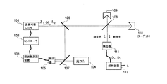
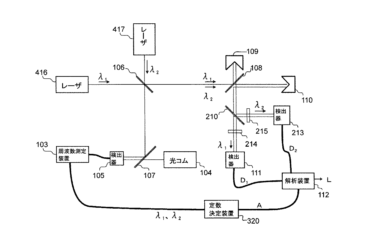
本発明の第1実施形態にかかる距離測定装置の構成を図2に示す。 FIG. 2 shows the configuration of the distance measuring apparatus according to the first embodiment of the present invention.
本実施形態では、波長(周波数)可変レーザ101の出力光をビームスプリッタ106で分割する。一方の光をビームスプリッタ108で分割し、一方は、例えばレトロリフレクタでなる参照鏡109で反射させて参照光とする。他方は、距離(変位)の測定対象である、例えばレトロリフレクタでなるターゲット110を照射し、そこからの反射光である測定光と、前記参照光をビームスプリッタ108で重ね合せる。参照光と測定光の信号を検出器111によって受光し、干渉強度信号により、干渉計本体からターゲット110までの距離(ターゲット110の変位)を測定する。
In this embodiment, the output light of the wavelength (frequency)
又、ビームスプリッタ106からの反射光を、ビームスプリッタ107を介して光コム104と重ね合わせて、検出器105で受光する。光コム104と波長可変レーザ101のビート信号を周波数測定装置103で周波数解析して、コントローラ102により、レーザ101の発振波長(周波数)をフィードバック制御する。
The reflected light from the
式(1)に従って、干渉計本体からターゲット110までの幾何学距離Lを測定するために、波長可変レーザ101と光コム104とのビート信号を見ながら、レーザ101の発振波長を定数Aに応じた所定の波長λ1にフィードバック制御して、光波干渉による距離測定値D1を得る。次に、同様に波長λ1とは異なる所定の波長λ2で測定を行い、それぞれの所定の波長λ1、λ2で得られた距離測定値D1とD2から、解析装置112で、式(1)により幾何学距離Lを算出する。
In order to measure the geometric distance L from the interferometer body to the
波長λ1とλ2の誤差δλ1とδλ2による幾何学距離Lの測定誤差Lerrorは、式(1)をλ1とλ2で偏微分したものから、次式(3)で示される。 The measurement error L error of the geometric distance L due to the errors δλ 1 and δλ 2 of the wavelengths λ 1 and λ 2 is expressed by the following equation (3) from the partial differentiation of the equation (1) by λ 1 and λ 2. .
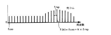
光コム104は、セシウムの原子時計を基準にして光の周波数を15桁以上の精度で測定できる装置である。従って、所定の波長λ1とλ2は、最大で15桁の精度で制御可能である。定数Aは、おおよそ2桁であることから、レーザ光の波長変動に起因する測定誤差Lerrorは、最大で13桁の精度まで高めることが出来る。この値は、幾何学距離1mを干渉測定する際に、誤差が1pm以下であることを示している。
The
第1実施形態の測定手順をまとめると、次のようになる。
(1)レーザ101の波長を設計波長λ1に制御する。
(2)干渉測定し、距離測定値D1を得る。
(3)レーザ101の波長を設計波長λ2に制御する。
(4)干渉測定し、距離測定値D2を得る。
(5)予め設計した波長λ1とλ2の定数Aの値を使った式(1)に代入し、幾何学距離Lを算出する。
The measurement procedure of the first embodiment is summarized as follows.
(1) The wavelength of the
(2) The interferometric measurement is performed to obtain the distance measurement value D 1.
(3) The wavelength of the
(4) The interferometric measurement is performed to obtain the distance measurement value D 2.
(5) The geometric distance L is calculated by substituting the equation (1) using the values of constants A of wavelengths λ 1 and λ 2 designed in advance.
図2では、一つのレーザ101を波長λ1とλ2に可変し、それぞれ順次測定する方法を示しているが、図3に示す第2実施形態のように、2波長以上を同時に出力するレーザ201を使って、所定の波長λ1とλ2による干渉信号を分割して同時に取る光学系(ビームスプリッタ210、バンドパスフィルタ214、215)を設けても良い。この場合、検出器105や周波数測定装置103からなる波長可変レーザ201の周波数測定系を波長λ1とλ2用にそれぞれ別々に用意しても構わないし、図3に示したように、一つの周波数測定系で、両方の波長(周波数)λ1、λ2を測定して制御することも可能である。
FIG. 2 shows a method in which one
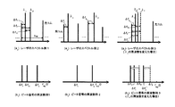
図4は、レーザの発振スペクトルと、その時に得られる干渉ビート信号の例を模式的に示している。図4(a1)に示す如く、所定の波長λ1とλ2と光コム104の干渉のビート信号を、光コム104の周波数間隔frepの1/2までの範囲で観察した場合には、図4(b1)に示す如く、それぞれの差の組み合わせの数の周波数のビート信号Δf1、Δf2、Δf12が観測される。一方、図4(a2)に示す如く、所定の波長λ1とλ2が、光コム104の異なる周波数(次数)との間で干渉している場合には、図4(b2)に示す如く、波長λ1とλ2は、それぞれの近隣の光との差の周波数のビート信号Δf1、Δf2が検出される。このような状況で、図4(a3)に示す如く、いずれかの波長(図ではλ2)を変化させると、変化させた分だけビート信号の周波数の変化が生じる。この現象を活用すれば、1つの周波数測定系で、波長λ1とλ2を区別することが可能である。
FIG. 4 schematically shows an example of a laser oscillation spectrum and an interference beat signal obtained at that time. As shown in FIG. 4 (a 1 ), when the beat signal of interference between the predetermined wavelengths λ 1 and λ 2 and the
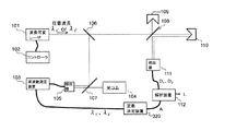
又、本発明を利用すれば、図5に示す第3実施形態のような構成での干渉測定への応用も可能である。 Further, if the present invention is used, it can be applied to interference measurement with the configuration as in the third embodiment shown in FIG.
本実施形態では、波長可変レーザ101を任意の波長λ1’で発振させて、距離測定値D1を得る。次に、波長λ1’とは異なる任意の波長λ2’で発振させて、距離測定値D2を得る。距離測定値D1とD2を得た際の正確な波長を、検出器105や周波数測定装置103などからなる周波数測定系で測定し、その結果を式(1)の定数Aの値に反映させて、幾何学距離Lを算出する。
In the present embodiment, the wavelength
定数Aは、波長の組み合わせによって決まる値である。そのため、予め波長の組み合わせに応じた、定数Aの算出テーブルや関数などを用意しておき、波長の組み合わせによって、定数決定装置320で、定数Aの誤差が幾何学距離Lに影響を与えない範囲で、必要な値を読み出してくればよい。なお、定数決定装置320の機能を、解析装置112内に入れることもできる。
The constant A is a value determined by a combination of wavelengths. Therefore, a constant A calculation table or function corresponding to the combination of wavelengths is prepared in advance, and the range in which the error of the constant A does not affect the geometric distance L in the
本実施形態では、レーザ101の波長を制御するための特別な装置も不要で、例えば半導体レーザのように電流可変で簡単に波長を変えられるようなレーザが使用できるために、測定装置を極めて簡素化することが出来る。
In this embodiment, there is no need for a special device for controlling the wavelength of the
本実施形態の測定手順をまとめると次のようになる。
(1)レーザ101を任意の波長λ1’で発振させる。
(2)干渉測定し、距離測定値D1を得ると同時に、そのときの正確な発振波長λ1を測定する。
(3)レーザ101を別の波長λ2’に可変し発振させる。
(4)干渉測定し、距離測定値D2を得ると同時に、そのときの正確な発振波長λ2を測定する。
(5)距離測定値D1とD2と正確な波長λ1とλ2の組み合わせによる定数Aを使った式(1)に代入し、幾何学距離Lを算出する。
The measurement procedure of this embodiment is summarized as follows.
(1) The
(2) Interferometric measurement is performed to obtain a distance measurement value D 1 , and at the same time, an accurate oscillation wavelength λ 1 is measured.
(3) The
(4) Interferometric measurement is performed to obtain a distance measurement value D 2 , and at the same time, an accurate oscillation wavelength λ 2 is measured.
(5) The geometric distance L is calculated by substituting into the equation (1) using the constant A based on the combination of the distance measurement values D 1 and D 2 and the exact wavelengths λ 1 and λ 2 .
又、本発明の手法を応用すれば、図6に示す第4実施形態の如く、発振波長の安定度が低く安価なレーザを使っても、高精度な幾何学距離Lの測定が実現できる。 If the method of the present invention is applied, the geometric distance L can be measured with high accuracy even when an inexpensive laser with low oscillation wavelength stability is used as in the fourth embodiment shown in FIG.
本実施形態では、波長λ1を発振するレーザ416と波長λ2を発振するレーザ417を同軸に重ね合わせ、参照鏡109とターゲット110からなる干渉光学系に入射する。波長λ1とλ2によって、距離測定値D1とD2を得て、式(1)によって幾何学距離Lを算出する。その際の波長λ1とλ2の正確な値は、検出器105や周波数測定装置103からなる周波数測定系によって得られたものを使用し、また、定数Aも先に示した方法によって正確に測定した波長λ1とλ2を元に、導き出したものを使用すれば良い。距離測定値D1とD2のそれぞれを測定した瞬間の波長λ1とλ2が得られる本実施形態においては、たとえ、レーザ416、417の周波数が不安定であったとしても、幾何学距離Lに大きな影響は及ぼさない。
In the present embodiment, a
これまでは、2波長のレーザを使った屈折率補正の方法について示したが、図7に示す第5実施形態のように、3波長以上の複数の波長を使って、更に精度の高い屈折率補正をすることも可能である。 Up to now, the refractive index correction method using a two-wavelength laser has been shown. However, as in the fifth embodiment shown in FIG. 7, a more accurate refractive index is obtained using a plurality of wavelengths of three or more wavelengths. It is also possible to make corrections.
本実施形態では、波長可変レーザ101の波長λ1、λ2、λ3・・・によって、距離測定値D1、D2、D3・・・を得て、それぞれの組み合わせによって、幾何学距離L12、L23、L31・・・を算出し、平均値を取るなど処置をすることによって、2波長を使う場合よりも、高精度な幾何学距離Lの測定を実現することができる。 In this embodiment, distance measurement values D 1 , D 2 , D 3 ... Are obtained from the wavelengths λ 1 , λ 2 , λ 3. By calculating L 12 , L 23 , L 31 ... And taking an average value, measurement of the geometric distance L can be realized with higher accuracy than when two wavelengths are used.
他にも例えば、3つの距離測定値D1、D2、D3と波長の組み合わせによってきまる定数Aiを使って、前出の式(2)に代入し、幾何学距離Lを決定することもできる。 In addition, for example, the geometric distance L is determined by substituting into the above equation (2) using the constant A i determined by the combination of the three distance measurement values D 1 , D 2 , D 3 and the wavelength. You can also.
ここで示した方法は、4波長以上の複数波長を使って幾何学的距離Lを決定すれば、更に効果的になる。また、3波長以上の任意の波長λ1、λ2、λ3・・・で距離測定値D1、D2、D3・・・を得て、それぞれの距離測定値D1、D2、D3・・・を得た時の波長λ1、λ2、λ3・・・を光コムを使って正確に測定し、波長の組み合わせに応じた定数Aiを使って、幾何学距離Lを算出しても良い。 The method shown here becomes more effective if the geometric distance L is determined using a plurality of wavelengths of four or more wavelengths. Further, distance measurement values D 1 , D 2 , D 3 ... Are obtained at arbitrary wavelengths λ 1 , λ 2 , λ 3 ... Of three or more wavelengths, and the distance measurement values D 1 , D 2 ,. The wavelengths λ 1 , λ 2 , λ 3 ... When D 3 ... Are obtained are accurately measured using an optical comb, and the geometric distance L is determined using a constant A i corresponding to the wavelength combination. May be calculated.
本実施形態の場合には、波長数を増やした場合でもそれぞれに安定度の高い高価なレーザが個別に必要なわけでもないために、より高精度な幾何学距離Lの測定が簡単に実現できる。 In the case of the present embodiment, even when the number of wavelengths is increased, an expensive laser with high stability is not necessarily required for each, and therefore, the measurement of the geometric distance L with higher accuracy can be easily realized. .
本実施形態の測定手順をまとめると、次のようになる。
(1)レーザ101の波長を設計波長λ1に制御する。
(2)干渉測定し、距離測定値D1を得る。
(3)レーザ101の波長を設計波長λ2に制御する。
(4)干渉測定し、距離測定値D2を得る。
(5)レーザ101の波長を設計波長λ3に制御する。
(6)干渉測定し、距離測定値D3を得る。
(7)波長λ1とλ2とλ3の組み合わせに応じた定数Aiの値を使った式(3)で、幾何学距離Lを算出する。
The measurement procedure of this embodiment is summarized as follows.
(1) The wavelength of the
(2) The interferometric measurement is performed to obtain the distance measurement value D 1.
(3) The wavelength of the
(4) The interferometric measurement is performed to obtain the distance measurement value D 2.
(5) The wavelength of the
(6) The interferometric measurement is performed to obtain the distance measurement value D 3.
(7) The geometric distance L is calculated by the equation (3) using the value of the constant A i corresponding to the combination of the wavelengths λ 1 , λ 2 and λ 3 .
それぞれの実施形態の中で、光の周波数を測定する装置として示した光コム104は、コムのスペクトル間隔内の限られた周波数領域ごとに高い分解能できることが基本となっている。そのため、光コム104のどの周波数の光との干渉によって生じたビート信号なのか、別途、次数Nを決定する必要がある。レーザの発振周波数の予備値やレーザ周波数の可変時の分解能などによって、次数Nを決定できない場合には、図8に示す第6実施形態のように、波長計601などの波長を測定できる手段と併用して、次数Nを決定し、波長可変レーザ101の波長λ1、λ2を測定して、発振周波数の制御に使用しても良いし、図3に示した第2実施形態に併用して、幾何学距離Lの算出に使用しても良い。
In each embodiment, the
前記実施形態においては、参照鏡109として、ターゲット110と同じレトロリフレクタを用いていたので、光軸が合わせ易く、調整が容易である。なお、参照鏡の種類は、レトロリフレクタに限定されず、平面鏡であっても良い。
In the embodiment, since the same retro reflector as the
101、201…波長可変レーザ
102…コントローラ
103…周波数測定装置
104…光コム
105、111、213…検出器
106、107、108、210…ビームスプリッタ
109…参照鏡
110…ターゲット
112…解析装置
214、215…バンドパスフィルタ
320…定数決定装置
416、417…レーザ
601…波長計
DESCRIPTION OF
Claims (16)
光コムを用いて前記複数のレーザ光の波長を測定することを特徴とする光波干渉による距離測定方法。 When measuring the geometric distance from the main body of the interferometer to the target with high accuracy by correcting the refractive index of air from the distance measurement value obtained by light wave interference measurement using laser light of multiple wavelengths,
A distance measurement method using light wave interference, wherein the wavelengths of the plurality of laser beams are measured using an optical comb.
L=D2−A1(D2−D1)−A2(D3−D1)
を用いて、前記幾何学距離Lを決定することを特徴とする請求項1乃至6のいずれかに記載の光波干渉による距離測定方法。 Three distance measurements D 1 , D 2 , D 3 and laser light affected by the air refractive index from the interferometer body to the target, obtained by laser light with wavelengths λ 1 , λ 2 , and λ 3 , respectively. Using a constant A i determined by the combination of wavelengths λ 1 , λ 2 , and λ 3 , L = D 2 −A 1 (D 2 −D 1 ) −A 2 (D 3 −D 1 )
7. The distance measurement method using light wave interference according to claim 1, wherein the geometric distance L is determined by using.
前記複数のレーザ光の波長を測定するための光コムを備えたことを特徴とする光波干渉による距離測定装置。 A distance measurement device for measuring the geometric distance from the interferometer body to the target with high accuracy by correcting the refractive index of air from the distance measurement value obtained by optical interference measurement using laser beams of multiple wavelengths. In
A distance measuring apparatus using light wave interference, comprising an optical comb for measuring wavelengths of the plurality of laser beams.
L=D2−A1(D2−D1)−A2(D3−D1)
を用いて、前記幾何学距離Lを決定する手段を備えたことを特徴とする請求項9乃至14のいずれかに記載の光波干渉による距離測定装置。 Three distance measurements D 1 , D 2 , D 3 and laser light affected by the air refractive index from the interferometer body to the target, obtained by laser light with wavelengths λ 1 , λ 2 , and λ 3 , respectively. Using a constant A i determined by the combination of wavelengths λ 1 , λ 2 , and λ 3 , L = D 2 −A 1 (D 2 −D 1 ) −A 2 (D 3 −D 1 )
15. The distance measuring device using light wave interference according to claim 9, further comprising means for determining the geometric distance L using a.
Priority Applications (3)
| Application Number | Priority Date | Filing Date | Title |
|---|---|---|---|
| JP2008198312A JP5511163B2 (en) | 2008-07-31 | 2008-07-31 | Distance measuring method and apparatus by light wave interference |
| US12/511,406 US8368900B2 (en) | 2008-07-31 | 2009-07-29 | Lightwave interferometric distance measuring method and apparatus using an optical comb |
| EP09166895.4A EP2149779B1 (en) | 2008-07-31 | 2009-07-30 | Lightwave interferometric distance measuring method and apparatus |
Applications Claiming Priority (1)
| Application Number | Priority Date | Filing Date | Title |
|---|---|---|---|
| JP2008198312A JP5511163B2 (en) | 2008-07-31 | 2008-07-31 | Distance measuring method and apparatus by light wave interference |
Publications (2)
| Publication Number | Publication Date |
|---|---|
| JP2010038558A true JP2010038558A (en) | 2010-02-18 |
| JP5511163B2 JP5511163B2 (en) | 2014-06-04 |
Family
ID=41328944
Family Applications (1)
| Application Number | Title | Priority Date | Filing Date |
|---|---|---|---|
| JP2008198312A Expired - Fee Related JP5511163B2 (en) | 2008-07-31 | 2008-07-31 | Distance measuring method and apparatus by light wave interference |
Country Status (3)
| Country | Link |
|---|---|
| US (1) | US8368900B2 (en) |
| EP (1) | EP2149779B1 (en) |
| JP (1) | JP5511163B2 (en) |
Cited By (4)
| Publication number | Priority date | Publication date | Assignee | Title |
|---|---|---|---|---|
| JP2016138795A (en) * | 2015-01-27 | 2016-08-04 | 株式会社東京精密 | Interference measurement device and interference measurement method |
| KR101792632B1 (en) * | 2016-06-01 | 2017-11-01 | 한국표준과학연구원 | Spectral-domain Interferometric System For Measurement Of Absolute Distances Free From Non-measurable Range and Directional Ambiguity |
| JP2018503872A (en) * | 2014-12-29 | 2018-02-08 | エーエスエムエル ホールディング エヌ.ブイ. | Feedback control system for alignment system |
| KR20220125431A (en) * | 2021-03-05 | 2022-09-14 | 부산대학교 산학협력단 | System and Method for Measuring Optical Interferometric Distance using Multiple Optical Frequency Stepped Scanning Laser |
Families Citing this family (10)
| Publication number | Priority date | Publication date | Assignee | Title |
|---|---|---|---|---|
| CN102679950B (en) * | 2012-05-18 | 2014-06-18 | 中国航空工业集团公司北京长城计量测试技术研究所 | Distance measuring device and method based on three-wavelength femtosecond laser |
| EP2816315B1 (en) * | 2013-06-18 | 2015-09-23 | Hexagon Technology Center GmbH | Interferometric determination of distance change with laser diode, high bandwidth detection and fast signal processing |
| PL223582B1 (en) | 2013-08-02 | 2016-10-31 | Aic Spółka Akcyjna | Pipe of the fired heat-exchanger |
| JP6553967B2 (en) | 2015-07-14 | 2019-07-31 | 株式会社ミツトヨ | Instantaneous phase shift interferometer |
| CN105445749A (en) * | 2015-11-13 | 2016-03-30 | 中国人民解放军空军装备研究院雷达与电子对抗研究所 | Multi-pulse laser range measuring system and multi-pulse laser range measuring method based on wavelength division |
| CN106370111B (en) * | 2016-09-23 | 2019-11-26 | 中国航空工业集团公司北京长城计量测试技术研究所 | A kind of femtosecond laser measuring motion and method for surveying facies principle based on frequency conversion |
| US11598628B1 (en) * | 2017-06-15 | 2023-03-07 | Ball Aerospace & Technologies Corp. | High dynamic range picometer metrology systems and methods |
| DE102018211913B4 (en) | 2018-07-17 | 2022-10-13 | Carl Zeiss Industrielle Messtechnik Gmbh | Device and method for detecting an object surface using electromagnetic radiation |
| JP2021148634A (en) * | 2020-03-19 | 2021-09-27 | 株式会社ミツトヨ | Laser interference device |
| CN111609798B (en) * | 2020-05-12 | 2021-04-16 | 浙江理工大学 | Device and method for measuring absolute distance of variable synthetic wavelength locked to dynamic sideband |
Citations (4)
| Publication number | Priority date | Publication date | Assignee | Title |
|---|---|---|---|---|
| JP2553276B2 (en) * | 1991-03-27 | 1996-11-13 | エイチイー・ホールディングス・インコーポレーテッド・ディービーエー・ヒューズ・エレクトロニクス | Three-wavelength optical measuring device and method |
| JPH08320206A (en) * | 1995-03-23 | 1996-12-03 | Nikon Corp | Optical interference measuring apparatus and optical interference measuring method |
| JPH0961109A (en) * | 1995-08-24 | 1997-03-07 | Nikon Corp | Light wave interference measuring device |
| JP2007040994A (en) * | 2005-08-01 | 2007-02-15 | Mitsutoyo Corp | Interference measuring system |
Family Cites Families (5)
| Publication number | Priority date | Publication date | Assignee | Title |
|---|---|---|---|---|
| US628456A (en) * | 1898-12-03 | 1899-07-11 | Albert Fuller | Injector. |
| JP3423229B2 (en) | 1998-11-17 | 2003-07-07 | 株式会社ミツトヨ | Light wave interferometer and length measuring method using light wave interferometer |
| JP3739987B2 (en) * | 2000-02-18 | 2006-01-25 | 財団法人神奈川科学技術アカデミー | Tomography equipment |
| WO2006019181A1 (en) * | 2004-08-18 | 2006-02-23 | National University Corporation Tokyo University Of Agriculture And Technology | Shape measurement method, shape measurement device, and frequency comb light generation device |
| KR100951618B1 (en) * | 2008-02-19 | 2010-04-09 | 한국과학기술원 | Absolute distance measurement method and system using optical frequency generator |
-
2008
- 2008-07-31 JP JP2008198312A patent/JP5511163B2/en not_active Expired - Fee Related
-
2009
- 2009-07-29 US US12/511,406 patent/US8368900B2/en active Active
- 2009-07-30 EP EP09166895.4A patent/EP2149779B1/en not_active Not-in-force
Patent Citations (4)
| Publication number | Priority date | Publication date | Assignee | Title |
|---|---|---|---|---|
| JP2553276B2 (en) * | 1991-03-27 | 1996-11-13 | エイチイー・ホールディングス・インコーポレーテッド・ディービーエー・ヒューズ・エレクトロニクス | Three-wavelength optical measuring device and method |
| JPH08320206A (en) * | 1995-03-23 | 1996-12-03 | Nikon Corp | Optical interference measuring apparatus and optical interference measuring method |
| JPH0961109A (en) * | 1995-08-24 | 1997-03-07 | Nikon Corp | Light wave interference measuring device |
| JP2007040994A (en) * | 2005-08-01 | 2007-02-15 | Mitsutoyo Corp | Interference measuring system |
Non-Patent Citations (6)
| Title |
|---|
| JPN6013011339; Jonghan Jin, Young-Jin Kim, Yunseok Kim and Seung-Woo Kim: '"Absolute length calibration of gauge blocks using optical comb of a femtosecond pulse laser"' OPTICS EXPRESS Vol.14, No.13, 20060626, pages 5968-5974 * |
| JPN6013011343; Nicolas Schuler, Yves Salvade, Samuel Leveque, Rene Dandliker, Ronald Holzwarth: '"Frequency-comb-referenced two-wavelength source for absolute distance measurement"' OPTICS LETTERS Vol.31, No.21, 200611, pages 3101-3103 * |
| JPN6013011345; Mikko Merimma, K. Nyholm, M. Vainio, Antti Lassila: '"Traceability of Laser Frequency Calibrations at MIKES"' IEEE TRANSACTIONS ON INSTRUMENTATION AND MEASUREMENT Vol.56, No.2, 200704, pages 500-504 * |
| JPN6013011349; Youichi Bitou, Thomas R. Schibli, Kaoru Minoshima: '"Accurate wide-range displacement measurement using tunable diode laser and optical frequency comb g' OPTICS EXPRESS Vol.14, No.2, 200601, pages 644-654 * |
| JPN6013011353; T.R.Schibli, K.Minoshima, Y.Bitou, F.-L.Hong, H.Inaba, A.Onae, H.Matsumoto: '"Displacement metrology with sub-pm resolution in air based on a fs-comb wavelength synthesizer"' OPTICS EXPRESS Vol.14, No.13, 200606, pages 5984-5993 * |
| JPN6013011356; Yves Salvade, Nicolas Schuler, Samuel Leveque, Sebastien Le Floch: '"High-accuracy absolute distance measurement using frequency comb referenced multiwavelength source"' APPLIED OPTICS Vol.47, No.14, 20080510, pages 2715-2720 * |
Cited By (7)
| Publication number | Priority date | Publication date | Assignee | Title |
|---|---|---|---|---|
| JP2018503872A (en) * | 2014-12-29 | 2018-02-08 | エーエスエムエル ホールディング エヌ.ブイ. | Feedback control system for alignment system |
| US10082740B2 (en) | 2014-12-29 | 2018-09-25 | Asml Holding N.V. | Feedback control system of an alignment system |
| JP2016138795A (en) * | 2015-01-27 | 2016-08-04 | 株式会社東京精密 | Interference measurement device and interference measurement method |
| KR101792632B1 (en) * | 2016-06-01 | 2017-11-01 | 한국표준과학연구원 | Spectral-domain Interferometric System For Measurement Of Absolute Distances Free From Non-measurable Range and Directional Ambiguity |
| WO2017209352A1 (en) * | 2016-06-01 | 2017-12-07 | 한국표준과학연구원 | Spectroscopic interferometer system for measuring absolute distance without unmeasurable range and directional ambiguity |
| KR20220125431A (en) * | 2021-03-05 | 2022-09-14 | 부산대학교 산학협력단 | System and Method for Measuring Optical Interferometric Distance using Multiple Optical Frequency Stepped Scanning Laser |
| KR102571110B1 (en) | 2021-03-05 | 2023-08-25 | 부산대학교 산학협력단 | System and Method for Measuring Optical Interferometric Distance using Multiple Optical Frequency Stepped Scanning Laser |
Also Published As
| Publication number | Publication date |
|---|---|
| US20100026983A1 (en) | 2010-02-04 |
| EP2149779B1 (en) | 2013-06-19 |
| EP2149779A1 (en) | 2010-02-03 |
| US8368900B2 (en) | 2013-02-05 |
| JP5511163B2 (en) | 2014-06-04 |
Similar Documents
| Publication | Publication Date | Title |
|---|---|---|
| JP5511163B2 (en) | Distance measuring method and apparatus by light wave interference | |
| JP5226078B2 (en) | Interferometer device and method of operating the same | |
| EP0646767B1 (en) | Interferometric distance measuring apparatus | |
| JP5265918B2 (en) | Optical feedback from mode select tuner | |
| JPH0749207A (en) | Absolute interference measuring method and laser interferometer suitable for method thereof | |
| US10024647B2 (en) | Method of air refractive index correction for absolute long distance measurement | |
| WO2016084263A1 (en) | Narrowband laser device | |
| JP2010230653A (en) | Optical interference measuring apparatus | |
| JP2009300263A (en) | Two-wavelength laser interferometer and method of adjusting optical axis in the same | |
| EP2634525A1 (en) | Absolute distance measuring multiwavelength interferometer | |
| JP5511162B2 (en) | Multi-wavelength interference displacement measuring method and apparatus | |
| JP2013083581A (en) | Measuring device | |
| JP6628030B2 (en) | Distance measuring device and method | |
| JP6635758B2 (en) | Refractive index correction method, distance measuring method and distance measuring device | |
| JP2554363B2 (en) | Optical interferometer | |
| JP6503618B2 (en) | Distance measuring device and method thereof | |
| US20120212746A1 (en) | Interferometer and measurement method | |
| JP2012184967A (en) | Wavelength scanning interferometer | |
| US20220206145A1 (en) | Optical distance measurement device and machining device | |
| JP2013057619A (en) | Measurement apparatus and measurement method | |
| JP6193644B2 (en) | Displacement measuring device and displacement measuring method | |
| US20230288562A1 (en) | Optical interferometric range sensor | |
| US11598628B1 (en) | High dynamic range picometer metrology systems and methods | |
| JP2024115237A (en) | Optical path difference measuring device and vibration measuring device | |
| JP2001280914A (en) | Method of measuring optical interference |
Legal Events
| Date | Code | Title | Description |
|---|---|---|---|
| A621 | Written request for application examination |
Free format text: JAPANESE INTERMEDIATE CODE: A621 Effective date: 20110601 |
|
| A977 | Report on retrieval |
Free format text: JAPANESE INTERMEDIATE CODE: A971007 Effective date: 20130228 |
|
| A131 | Notification of reasons for refusal |
Free format text: JAPANESE INTERMEDIATE CODE: A131 Effective date: 20130312 |
|
| A521 | Request for written amendment filed |
Free format text: JAPANESE INTERMEDIATE CODE: A523 Effective date: 20130513 |
|
| TRDD | Decision of grant or rejection written | ||
| A01 | Written decision to grant a patent or to grant a registration (utility model) |
Free format text: JAPANESE INTERMEDIATE CODE: A01 Effective date: 20140311 |
|
| A61 | First payment of annual fees (during grant procedure) |
Free format text: JAPANESE INTERMEDIATE CODE: A61 Effective date: 20140325 |
|
| R150 | Certificate of patent or registration of utility model |
Ref document number: 5511163 Country of ref document: JP Free format text: JAPANESE INTERMEDIATE CODE: R150 |
|
| R250 | Receipt of annual fees |
Free format text: JAPANESE INTERMEDIATE CODE: R250 |
|
| R250 | Receipt of annual fees |
Free format text: JAPANESE INTERMEDIATE CODE: R250 |
|
| LAPS | Cancellation because of no payment of annual fees |