JP2010038210A - Control apparatus for vehicle automatic transmission - Google Patents
Control apparatus for vehicle automatic transmission Download PDFInfo
- Publication number
- JP2010038210A JP2010038210A JP2008200088A JP2008200088A JP2010038210A JP 2010038210 A JP2010038210 A JP 2010038210A JP 2008200088 A JP2008200088 A JP 2008200088A JP 2008200088 A JP2008200088 A JP 2008200088A JP 2010038210 A JP2010038210 A JP 2010038210A
- Authority
- JP
- Japan
- Prior art keywords
- way clutch
- automatic transmission
- torque
- increased
- output torque
- Prior art date
- Legal status (The legal status is an assumption and is not a legal conclusion. Google has not performed a legal analysis and makes no representation as to the accuracy of the status listed.)
- Granted
Links
Images


Classifications
-
- G—PHYSICS
- G06—COMPUTING; CALCULATING OR COUNTING
- G06F—ELECTRIC DIGITAL DATA PROCESSING
- G06F17/00—Digital computing or data processing equipment or methods, specially adapted for specific functions
-
- F—MECHANICAL ENGINEERING; LIGHTING; HEATING; WEAPONS; BLASTING
- F16—ENGINEERING ELEMENTS AND UNITS; GENERAL MEASURES FOR PRODUCING AND MAINTAINING EFFECTIVE FUNCTIONING OF MACHINES OR INSTALLATIONS; THERMAL INSULATION IN GENERAL
- F16H—GEARING
- F16H61/00—Control functions within control units of change-speed- or reversing-gearings for conveying rotary motion ; Control of exclusively fluid gearing, friction gearing, gearings with endless flexible members or other particular types of gearing
- F16H61/04—Smoothing ratio shift
- F16H61/0437—Smoothing ratio shift by using electrical signals
-
- B—PERFORMING OPERATIONS; TRANSPORTING
- B60—VEHICLES IN GENERAL
- B60W—CONJOINT CONTROL OF VEHICLE SUB-UNITS OF DIFFERENT TYPE OR DIFFERENT FUNCTION; CONTROL SYSTEMS SPECIALLY ADAPTED FOR HYBRID VEHICLES; ROAD VEHICLE DRIVE CONTROL SYSTEMS FOR PURPOSES NOT RELATED TO THE CONTROL OF A PARTICULAR SUB-UNIT
- B60W10/00—Conjoint control of vehicle sub-units of different type or different function
- B60W10/10—Conjoint control of vehicle sub-units of different type or different function including control of change-speed gearings
-
- F—MECHANICAL ENGINEERING; LIGHTING; HEATING; WEAPONS; BLASTING
- F16—ENGINEERING ELEMENTS AND UNITS; GENERAL MEASURES FOR PRODUCING AND MAINTAINING EFFECTIVE FUNCTIONING OF MACHINES OR INSTALLATIONS; THERMAL INSULATION IN GENERAL
- F16H—GEARING
- F16H61/00—Control functions within control units of change-speed- or reversing-gearings for conveying rotary motion ; Control of exclusively fluid gearing, friction gearing, gearings with endless flexible members or other particular types of gearing
- F16H61/04—Smoothing ratio shift
- F16H2061/044—Smoothing ratio shift when a freewheel device is disengaged or bridged
-
- F—MECHANICAL ENGINEERING; LIGHTING; HEATING; WEAPONS; BLASTING
- F16—ENGINEERING ELEMENTS AND UNITS; GENERAL MEASURES FOR PRODUCING AND MAINTAINING EFFECTIVE FUNCTIONING OF MACHINES OR INSTALLATIONS; THERMAL INSULATION IN GENERAL
- F16H—GEARING
- F16H59/00—Control inputs to control units of change-speed-, or reversing-gearings for conveying rotary motion
- F16H59/48—Inputs being a function of acceleration
-
- F—MECHANICAL ENGINEERING; LIGHTING; HEATING; WEAPONS; BLASTING
- F16—ENGINEERING ELEMENTS AND UNITS; GENERAL MEASURES FOR PRODUCING AND MAINTAINING EFFECTIVE FUNCTIONING OF MACHINES OR INSTALLATIONS; THERMAL INSULATION IN GENERAL
- F16H—GEARING
- F16H61/00—Control functions within control units of change-speed- or reversing-gearings for conveying rotary motion ; Control of exclusively fluid gearing, friction gearing, gearings with endless flexible members or other particular types of gearing
- F16H61/04—Smoothing ratio shift
- F16H61/0403—Synchronisation before shifting
-
- F—MECHANICAL ENGINEERING; LIGHTING; HEATING; WEAPONS; BLASTING
- F16—ENGINEERING ELEMENTS AND UNITS; GENERAL MEASURES FOR PRODUCING AND MAINTAINING EFFECTIVE FUNCTIONING OF MACHINES OR INSTALLATIONS; THERMAL INSULATION IN GENERAL
- F16H—GEARING
- F16H63/00—Control outputs from the control unit to change-speed- or reversing-gearings for conveying rotary motion or to other devices than the final output mechanism
- F16H63/40—Control outputs from the control unit to change-speed- or reversing-gearings for conveying rotary motion or to other devices than the final output mechanism comprising signals other than signals for actuating the final output mechanisms
- F16H63/50—Signals to an engine or motor
- F16H63/502—Signals to an engine or motor for smoothing gear shifts
Abstract
Description
本発明は、一方向クラッチの係合により成立させられる変速段を含む複数の変速段が選択的に成立させられる車両用自動変速機の制御装置に係り、特に、一方向クラッチが同期するときのショックを抑制する技術に関するものである。 The present invention relates to a control device for an automatic transmission for a vehicle in which a plurality of shift stages including a shift stage established by engagement of a one-way clutch are selectively established, and particularly when the one-way clutch is synchronized. The present invention relates to a technique for suppressing shock.
複数の摩擦係合装置及び一方向クラッチの何れかが選択的に係合されることにより変速比が異なる複数の変速段が成立させられる自動変速機を介して駆動力源例えばエンジンの動力を駆動輪側へ伝達する車両が良く知られている。そして、このような車両において、一方向クラッチが同期する(空転状態から係合(締結)状態となる)ときには、エンジントルク伝達がステップ的に行われることによる急激なトルクの立ち上がりと駆動系のねじり振動に起因したトルク振動によりショック(以下、同期ショックと称する)が発生することがある。 A driving force source, for example, engine power is driven through an automatic transmission in which a plurality of gear stages having different gear ratios are established by selectively engaging one of a plurality of friction engagement devices and a one-way clutch. Vehicles that transmit to the wheel side are well known. In such a vehicle, when the one-way clutch synchronizes (from the idling state to the engaged (engaged) state), a sudden torque rise due to stepwise engine torque transmission and torsion of the drive system A shock (hereinafter referred to as a synchronous shock) may occur due to torque vibration caused by the vibration.
上述した一方向クラッチの同期ショックを低減する為に、例えば特許文献1に記載された車両用自動変速機の制御装置では、再加速時に一方向クラッチの同期直前状態が検出されるとエンジン出力を低減するエンジントルクダウンを行って、一方向クラッチの同期時点で発生する急激なトルクの立ち上がりとトルク振動とを抑制している。
In order to reduce the synchronous shock of the one-way clutch described above, for example, in the control device for an automatic transmission for a vehicle described in
ところで、一方向クラッチの係合により成立させられる変速段において一方向クラッチが空転状態であるときには、自動変速機内は動力伝達経路が解放された所謂ニュートラル状態とされており、このような状態となり得る例えばアクセルオフの惰性走行(コースト走行)中にアクセルオンとなる加速要求がなされたとしてもエンジン回転速度が上昇して一方向クラッチが同期するまで駆動輪には駆動力が発生させられない。 By the way, when the one-way clutch is idling in the shift stage established by the engagement of the one-way clutch, the automatic transmission is in a so-called neutral state in which the power transmission path is released, and such a state can occur. For example, even if an acceleration request for turning on the accelerator is made during coasting with the accelerator off (coast running), no driving force is generated on the drive wheels until the engine speed increases and the one-way clutch is synchronized.
そこで、アクセルオンから一方向クラッチが同期するまでの時間を短くしてアクセルオンに対する駆動力発生の応答(以下、駆動力レスポンスと称する)を向上する為に、すなわち一方向クラッチの同期を促進する為に、アクセル開度に応じて通常出力されるエンジントルクよりもエンジントルクを上昇させる所謂エンジントルクアップを行うことが考えられる。 Therefore, in order to shorten the time from when the accelerator is turned on until the one-way clutch is synchronized to improve the response of driving force generation to the accelerator-on (hereinafter referred to as driving force response), that is, to promote the synchronization of the one-way clutch. Therefore, it is conceivable to perform so-called engine torque increase that increases the engine torque from the engine torque that is normally output according to the accelerator opening.
図12は、一方向クラッチの係合により成立させられる変速段において一方向クラッチが空転状態であるときに加速要求がなされた際の従来の制御作動を説明するタイムチャートである。図12において、t1時点にてアクセルオンとされると、一方向クラッチの同期に先だってその同期を促進する為にt2時点からエンジントルクアップが実行される。続いて、一方向クラッチが同期する直前のt3時点からは一方向クラッチの同期ショックを低減する為にエンジントルクアップに換えてエンジントルクダウンが実行される。そして、一方向クラッチが同期したt4時点から自動変速機の出力トルク(アウトプットトルク)がトルク振動を含みつつ立ち上がる。 FIG. 12 is a time chart for explaining a conventional control operation when an acceleration request is made when the one-way clutch is idling at a shift stage established by engagement of the one-way clutch. 12, when the accelerator-on at time point t 1, the engine torque up is executed from t 2 time to facilitate the synchronization prior to synchronization of the one-way clutches. Then, the engine torque down is executed in place of the engine torque up to reduce the synchronization shock of the one-way clutch from t 3 time just before the one-way clutch is synchronized. Then, the output torque of the automatic transmission (output torque) rises while including a torque vibration from t 4 when the one-way clutch is synchronized.
しかしながら、図12に示したような制御作動では、駆動力レスポンスの向上と同期ショックの低減との双方がエンジンの出力制御にて行われそれら双方を各々独立して制御できないことから、エンジントルクアップからエンジントルクダウンへの瞬時の切り換えが要求され、エンジントルク変化の応答性によっては駆動力レスポンスの向上と同期ショックの低減との両立が困難である可能性があった。例えば、駆動力レスポンスをより向上しようとしてエンジントルクアップ分を大きくするとエンジントルクダウンへの切換えを早くしなければならず、エンジントルク変化の応答性によっては同期ショックの低減が良好なものとならない恐れがあった。また、同期ショックをより低減しようとしてエンジントルクダウン分を大きくすると駆動力レスポンスが低下する恐れがあった。尚、上述したような課題は未公知である。 However, in the control operation as shown in FIG. 12, both the improvement of the driving force response and the reduction of the synchronous shock are performed by the engine output control, and both cannot be controlled independently. Therefore, there is a possibility that it is difficult to achieve both improvement of driving force response and reduction of synchronous shock depending on the response of engine torque change. For example, if the engine torque increase is increased in order to further improve the driving force response, switching to engine torque down must be made earlier, and depending on the response of the engine torque change, the synchronization shock may not be reduced satisfactorily. was there. Further, if the engine torque down is increased in order to further reduce the synchronous shock, the driving force response may be lowered. The above-described problem is not known.
本発明は、以上の事情を背景として為されたものであり、その目的とするところは、一方向クラッチの係合により成立させられる変速段において一方向クラッチが空転状態であるときに加速要求がなされた際に、駆動力レスポンスの向上と同期ショックの低減とを両立することができる車両用自動変速機の制御装置を提供することにある。 The present invention has been made against the background of the above circumstances. The purpose of the present invention is to provide an acceleration request when the one-way clutch is idling at a shift stage established by engagement of the one-way clutch. When it was made, it is providing the control apparatus of the automatic transmission for vehicles which can make the improvement of a driving force response and the reduction of a synchronous shock compatible.
前記目的を達成するための本発明の要旨とするところは、(a) 複数の摩擦係合装置及び一方向クラッチの何れかが選択的に係合されることにより変速比が異なる複数の変速段が成立させられる車両用自動変速機の制御装置であって、(b) 前記一方向クラッチの係合により成立させられる第1所定変速段においてその一方向クラッチが係合状態とされているか否かを判定する係合状態判定手段と、(c) 車両に対する加速要求の有無を判定する加速要求判定手段と、(d) 前記第1所定変速段における前記一方向クラッチの空転状態にて前記加速要求が発生した際に、その加速要求に伴ってその一方向クラッチが同期させられる回転方向に向かうことは継続させつつその一方向クラッチの空転状態が維持される第2所定変速段を成立させる為の摩擦係合装置にトルク容量を生じさせる同期前制御手段とを、含むことにある。 In order to achieve the above object, the gist of the present invention is that: (a) a plurality of shift stages having different gear ratios by selectively engaging any one of a plurality of friction engagement devices and a one-way clutch; (B) Whether or not the one-way clutch is engaged at a first predetermined shift speed established by engagement of the one-way clutch. (C) an acceleration request determination means for determining whether or not there is an acceleration request for the vehicle; and (d) the acceleration request in the idling state of the one-way clutch at the first predetermined shift stage. In order to establish a second predetermined shift stage that maintains the idling state of the one-way clutch while continuing to move in the rotational direction in which the one-way clutch is synchronized with the acceleration request. Friction engagement device And pre-synchronization control means for generating torque capacity in the device.
このようにすれば、前記第1所定変速段における前記一方向クラッチの空転状態にて前記加速要求が発生した場合には、同期前制御手段により一方向クラッチの空転状態が維持される第2所定変速段を成立させる為の摩擦係合装置にトルク容量が生じさせられるので、第1所定変速段における一方向クラッチの空転状態ではあるがすなわち一方向クラッチの同期前ではあるが自動変速機の出力トルク(ここでは駆動力、駆動トルクも同義)が発生させられる。この際、同期前制御手段により、第2所定変速段が成立させられわけではなく加速要求に伴って一方向クラッチが同期させられる回転方向に向かうことは継続させられるので、一方向クラッチは確実に同期させられて第1所定変速段が成立させられる。これにより、一方向クラッチの同期前に出力トルクが発生させられて駆動力レスポンスが向上する。加えて、一方向クラッチの同期時には既に出力トルクが発生していることから出力トルクの立ち上がりが生じず同期ショックが抑制される。 According to this configuration, when the acceleration request is generated in the idling state of the one-way clutch at the first predetermined gear, the second prescribed state in which the idling state of the one-way clutch is maintained by the pre-synchronization control means. Since the torque capacity is generated in the friction engagement device for establishing the gear stage, the output of the automatic transmission is in the idling state of the one-way clutch at the first predetermined gear stage, that is, before the one-way clutch is synchronized. Torque (here, driving force and driving torque are also synonymous) is generated. At this time, the pre-synchronization control means does not establish the second predetermined shift stage, but continues to move in the rotational direction in which the one-way clutch is synchronized with the acceleration request. The first predetermined shift speed is established in synchronization. As a result, an output torque is generated before the synchronization of the one-way clutch, and the driving force response is improved. In addition, since the output torque has already been generated during the synchronization of the one-way clutch, the output torque does not rise and the synchronous shock is suppressed.
別の見方をすれば、第2所定変速段を成立させる為の摩擦係合装置にトルク容量を生じさせることで、単に加速要求に伴って一方向クラッチが同期させられる回転方向へ向かうことに比較して緩やかな速度で同期させられる回転方向へ向かわせることもでき、それにより同期ショックを抑制することが可能になる。この際、単に加速要求に伴って一方向クラッチが同期させられることに比較して一方向クラッチの同期は遅延させられるが、同期前から出力トルクが発生させられていることから、駆動力レスポンスは向上させられるものの低下させられることはない。 From another point of view, the friction engagement device for establishing the second predetermined shift speed generates a torque capacity, which is compared with the direction of rotation in which the one-way clutch is synchronized with an acceleration request. Thus, the direction of rotation can be made to synchronize at a moderate speed, thereby making it possible to suppress a synchronous shock. At this time, the synchronization of the one-way clutch is delayed as compared with the case where the one-way clutch is simply synchronized with the acceleration request, but since the output torque is generated before the synchronization, the driving force response is Although it can be improved, it cannot be reduced.
従って、一方向クラッチの係合により成立させられる変速段において一方向クラッチが空転状態であるときに加速要求がなされた際に、駆動力レスポンスの向上と同期ショックの低減とを両立することができる車両用自動変速機の制御装置が提供される。 Therefore, when the acceleration request is made when the one-way clutch is idling at the shift stage established by the engagement of the one-way clutch, both improvement in driving force response and reduction in synchronous shock can be achieved. A control device for an automatic transmission for a vehicle is provided.
ここで、好適には、前記車両用自動変速機は、駆動力源から出力された動力を駆動輪側へ伝達する動力伝達装置であり、前記一方向クラッチは、前記加速要求に伴って前記車両用自動変速機の入力回転速度が上昇させられることで同期させられる回転方向に向かい、前記第2所定変速段は、前記第1所定変速段よりも前記車両用自動変速機の入力回転速度を低下させる高速段側の変速段であり、前記同期前制御手段は、前記加速要求時の要求量が大きい程大きくされた前記車両用自動変速機の出力トルクの目標値が得られ且つ前記一方向クラッチを同期させる回転方向へ向かわせる為の前記車両用自動変速機の入力回転速度の目標値に沿ってその入力回転速度が上昇させられるように、前記第2所定変速段を成立させる為の摩擦係合装置のトルク容量を発生させ且つ前記駆動力源の出力トルクを前記加速要求時の要求量に応じた要求出力トルクよりも上昇させる。このようにすれば、車両用自動変速機の出力トルクの目標値が得られるので、一方向クラッチの同期前から自動変速機の出力トルクが適切に発生させられる。加えて、前記一方向クラッチを同期させる回転方向へ向かわせるように前記車両用自動変速機の入力回転速度が上昇させられるので、前記一方向クラッチは確実に同期させられる。 Here, preferably, the automatic transmission for a vehicle is a power transmission device that transmits power output from a driving force source to a driving wheel side, and the one-way clutch is connected to the vehicle in response to the acceleration request. When the input rotational speed of the automatic transmission for the vehicle is increased, the second predetermined shift speed is lower than that of the first predetermined shift speed. And the pre-synchronization control means obtains a target value of the output torque of the vehicular automatic transmission that is increased as the required amount at the time of the acceleration request is larger, and the one-way clutch. Friction coefficient for establishing the second predetermined shift stage so that the input rotation speed is increased along the target value of the input rotation speed of the automatic transmission for vehicle for making the rotation direction to synchronize with each other. Combined device Increase than required output torque of and the output torque of the driving power source to generate a click volume according to the required amount of time the acceleration request. In this way, since the target value of the output torque of the vehicle automatic transmission can be obtained, the output torque of the automatic transmission can be appropriately generated before the synchronization of the one-way clutch. In addition, since the input rotational speed of the vehicular automatic transmission is increased so that the one-way clutch is rotated in the rotational direction in which the one-way clutch is synchronized, the one-way clutch is reliably synchronized.
また、好適には、前記車両用自動変速機の出力トルクは、前記第2所定変速段を成立させる為の摩擦係合装置のトルク容量が大きくされる程大きくされ且つ前記駆動力源の出力トルクの上昇分が大きくされる程大きくされる第1の所定の関係式に基づいて算出され、前記車両用自動変速機の入力回転速度の上昇分は、前記第2所定変速段を成立させる為の摩擦係合装置のトルク容量が大きくされる程小さくされ且つ前記駆動力源の出力トルクの上昇分が大きくされる程大きくされる第2の所定の関係式に基づいて算出されるものであり、前記同期前制御手段は、前記車両用自動変速機の出力トルクが運転者の操作に基づき求められた目標値となるように前記第1の所定の関係式及び前記第2の所定の関係式に基づいて前記トルク容量を発生させ且つ前記駆動力源の出力トルクを上昇させる。このようにすれば、前記車両用自動変速機の出力トルクの目標値が得られ且つ前記車両用自動変速機の入力回転速度が目標値に沿って上昇させられるように、第1の所定の関係式及び第2の所定の関係式に基づいて前記第2所定変速段を成立させる為の摩擦係合装置のトルク容量と前記駆動力源の出力トルクの上昇分とが算出され、その算出結果に基づいて摩擦係合装置の作動と駆動力源の出力とが適切に制御される。 Preferably, the output torque of the vehicle automatic transmission is increased as the torque capacity of the friction engagement device for establishing the second predetermined shift speed is increased, and the output torque of the driving force source is increased. The increase in the input rotational speed of the vehicle automatic transmission is calculated based on a first predetermined relational expression that is increased as the increase in the engine is increased. It is calculated based on a second predetermined relational expression that is decreased as the torque capacity of the friction engagement device is increased and increased as the increase in the output torque of the driving force source is increased. The pre-synchronization control means sets the first predetermined relational expression and the second predetermined relational expression so that the output torque of the vehicle automatic transmission becomes a target value obtained based on a driver's operation. Generate the torque capacity based on And increasing the output torque of the driving power source. In this case, the first predetermined relationship is established so that the target value of the output torque of the vehicle automatic transmission is obtained and the input rotational speed of the vehicle automatic transmission is increased along the target value. The torque capacity of the friction engagement device and the increase in the output torque of the driving force source for establishing the second predetermined shift stage are calculated based on the equation and the second predetermined relational expression. Based on this, the operation of the friction engagement device and the output of the driving force source are appropriately controlled.
また、好適には、前記一方向クラッチの同期後は、前記同期前制御手段による制御に替えて、前記駆動力源の要求出力トルクのみで前記車両用自動変速機の出力トルクの目標値が得られるように、前記第2所定変速段を成立させる為の摩擦係合装置のトルク容量を減少させ且つ前記駆動力源の出力トルクの上昇分を減少させる同期後制御手段を更に備える。このようにすれば、一方向クラッチの同期後は、前記同期前制御手段により発生させられた摩擦係合装置のトルク容量や駆動力源の出力トルクの上昇分が速やかに解除させられ、前記駆動力源の要求出力トルクのみで前記車両用自動変速機の出力トルクの目標値を得るという通常状態の制御に速やかに戻される。 Preferably, after the synchronization of the one-way clutch, the target value of the output torque of the vehicle automatic transmission is obtained only by the required output torque of the driving force source, instead of the control by the pre-synchronization control means. As described above, the control device further includes post-synchronization control means for reducing the torque capacity of the friction engagement device for establishing the second predetermined shift speed and reducing the increase in the output torque of the driving force source. In this way, after the synchronization of the one-way clutch, the increase in the torque capacity of the friction engagement device and the output torque of the driving force source generated by the pre-synchronization control means is quickly released, and the drive The control is quickly returned to the normal state in which the target value of the output torque of the vehicle automatic transmission is obtained only by the required output torque of the force source.
また、好適には、前記一方向クラッチの同期後の前記車両用自動変速機の出力トルクは、前記第2所定変速段を成立させる為の摩擦係合装置のトルク容量が大きくされる程小さくされ且つ前記駆動力源の出力トルクの上昇分が大きくされる程大きくされる第3の所定の関係式に基づいて算出されるものであり、前記同期後制御手段は、前記一方向クラッチの同期後の所定時間内に前記駆動力源の出力トルクの上昇分を零に向かって逓減させ、前記第2所定変速段を成立させる為の摩擦係合装置のトルク容量を前記第3の所定の関係式に従って逓減させる。このようにすれば、第3の所定の関係式に基づいて前記一方向クラッチの同期後の所定時間内に前記同期前制御手段により発生させられた摩擦係合装置のトルク容量や駆動力源の出力トルクの上昇分が解除させられる。 Preferably, the output torque of the vehicular automatic transmission after synchronization of the one-way clutch is reduced as the torque capacity of the friction engagement device for establishing the second predetermined shift speed is increased. In addition, the post-synchronization control means is calculated after the synchronization of the one-way clutch, and is calculated based on a third predetermined relational expression that increases as the increase in the output torque of the driving force source increases. The torque capacity of the frictional engagement device for establishing the second predetermined shift stage by gradually decreasing the increase in the output torque of the driving force source toward zero within a predetermined time of the third predetermined relational expression. Decrease according to In this case, the torque capacity of the friction engagement device and the driving force source generated by the pre-synchronization control means within a predetermined time after the synchronization of the one-way clutch based on the third predetermined relational expression. The increase in output torque is released.
また、好適には、前記車両用自動変速機は、複数組の遊星歯車装置の回転要素が摩擦係合装置によって選択的に連結されることにより複数のギヤ段(変速段)が択一的に達成される例えば前進4段、前進5段、前進6段、更にはそれ以上の変速段を有する等の種々の遊星歯車式多段変速機により構成される。この遊星歯車式多段変速機における摩擦係合装置としては、油圧アクチュエータによって係合させられる多板式、単板式のクラッチやブレーキ、或いはベルト式のブレーキ等の油圧式摩擦係合装置が広く用いられる。この油圧式摩擦係合装置を係合させるための作動油を供給するオイルポンプは、例えば走行用の駆動力源により駆動されて作動油を吐出するものでも良いが、駆動力源とは別に配設された専用の電動モータなどで駆動されるものでも良い。また、クラッチ或いはブレーキは、油圧式摩擦係合装置以外に電磁式係合装置例えば電磁クラッチや磁粉式クラッチ等であってもよい。 Preferably, in the automatic transmission for a vehicle, a plurality of gear stages (shift speeds) are alternatively selected by selectively connecting rotating elements of a plurality of sets of planetary gear devices by a friction engagement device. For example, it is constituted by various planetary gear type multi-stage transmissions having, for example, four forward speeds, five forward speeds, six forward speeds, and more. As a friction engagement device in this planetary gear type multi-stage transmission, a hydraulic friction engagement device such as a multi-plate type, a single plate type clutch or brake engaged by a hydraulic actuator, or a belt type brake is widely used. An oil pump that supplies hydraulic oil for engaging the hydraulic friction engagement device may be driven by a driving force source for traveling and discharges hydraulic oil, for example, but is arranged separately from the driving force source. It may be driven by a dedicated electric motor provided. Further, the clutch or brake may be an electromagnetic engagement device such as an electromagnetic clutch or a magnetic powder clutch in addition to the hydraulic friction engagement device.
また、好適には、上記油圧式摩擦係合装置を含む油圧制御回路は、例えばリニアソレノイドバルブの出力油圧を直接油圧式摩擦係合装置の油圧アクチュエータ(油圧シリンダ)にそれぞれ供給することが応答性の点で望ましいが、そのリニアソレノイドバルブの出力油圧をパイロット油圧として用いることによりシフトコントロールバルブを制御して、そのコントロールバルブから油圧アクチュエータに作動油を供給するように構成することもできる。 Preferably, the hydraulic control circuit including the hydraulic friction engagement device is responsive to, for example, supplying output hydraulic pressure of a linear solenoid valve directly to a hydraulic actuator (hydraulic cylinder) of the hydraulic friction engagement device. However, it is also possible to control the shift control valve by using the output hydraulic pressure of the linear solenoid valve as a pilot hydraulic pressure, and to supply hydraulic oil from the control valve to the hydraulic actuator.
また、好適には、上記リニアソレノイドバルブは、例えば複数の油圧式摩擦係合装置の各々に対応して1つずつ設けられるが、同時に係合したり係合、解放制御したりすることがない複数の油圧式摩擦係合装置が存在する場合には、それ等に共通のリニアソレノイドバルブを設けることもできるなど、種々の態様が可能である。また、必ずしも全ての油圧式摩擦係合装置の油圧制御をリニアソレノイドバルブで行う必要はなく、一部乃至全ての油圧制御をON−OFFソレノイドバルブのデューティ制御など、リニアソレノイドバルブ以外の調圧手段で行っても良い。 Preferably, one linear solenoid valve is provided, for example, corresponding to each of a plurality of hydraulic friction engagement devices. However, the linear solenoid valves are not engaged at the same time or controlled to be engaged or released. When there are a plurality of hydraulic friction engagement devices, various modes are possible, such as providing a common linear solenoid valve for them. In addition, it is not always necessary to control the hydraulic pressure of all the hydraulic friction engagement devices with the linear solenoid valve, and pressure control means other than the linear solenoid valve, such as duty control of the ON-OFF solenoid valve for part or all of the hydraulic control. You can go there.
また、好適には、前記走行用駆動力源としては、ガソリンエンジンやディーゼルエンジン等の内燃機関であるエンジンが広く用いられる。さらに、補助的な走行用動力源として、電動機等がこのエンジンに加えて用いられても良い。或いは、走行用駆動力源として電動機のみが用いられても良い。 Preferably, an engine that is an internal combustion engine such as a gasoline engine or a diesel engine is widely used as the driving power source for traveling. Further, an electric motor or the like may be used in addition to this engine as an auxiliary driving power source. Alternatively, only an electric motor may be used as a driving force source for traveling.
尚、この明細書で「油圧を供給する」という場合は、「油圧を作用させ」或いは「その油圧に制御された作動油を供給する」ことを意味する。 In this specification, “supplying hydraulic pressure” means “applying hydraulic pressure” or “supplying hydraulic oil controlled to the hydraulic pressure”.
以下、本発明の実施例を図面を参照しつつ詳細に説明する。 Hereinafter, embodiments of the present invention will be described in detail with reference to the drawings.
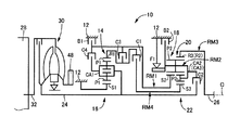
図1は、本発明が適用された車両用自動変速機(以下、自動変速機と表す)10の構成を説明する骨子図である。この自動変速機10は、車体に取り付けられる非回転部材としてのトランスミッションケース(以下、ケースと表す)12内において、ダブルピニオン型の第1遊星歯車装置14を主体として構成されている第1変速部16と、シングルピニオン型の第2遊星歯車装置18及びダブルピニオン型の第3遊星歯車装置20を主体として構成されている第2変速部22とを共通の軸心C上に備え、入力軸24の回転を変速して出力軸26から出力する。入力軸24は入力側回転部材に相当するものであり、本実施例では走行用の駆動力源であるエンジン28によって回転駆動されるトルクコンバータ30のタービン軸である。出力軸26は出力側回転部材に相当するものであり、例えば図4に示すように差動歯車装置(終減速機)34や一対の車軸36等を順次介して左右の駆動輪38を回転駆動する。
FIG. 1 is a skeleton diagram illustrating the configuration of a vehicular automatic transmission (hereinafter referred to as an automatic transmission) 10 to which the present invention is applied. The
尚、上記入力側回転部材は、自動変速機10により変速される前の回転部材であり、入力軸24の他にエンジン28のクランク軸32等が相当する。また、上記出力側回転部材は、自動変速機10により変速された入力側回転部材の回転が伝達される回転部材であり、出力軸26の他に差動歯車装置34や車軸36や駆動輪38等が相当する。また、この自動変速機10は中心線(軸心)Cに対して略対称的に構成されており、図1の骨子図においてはその軸心Cの下半分が省略されている。
The input side rotating member is a rotating member before being shifted by the
第1遊星歯車装置14はダブルピニオン型の遊星歯車装置であり、サンギヤS1、互いに噛み合う複数対のピニオンギヤP1、そのピニオンギヤP1を自転及び公転可能に支持するキャリヤCA1、ピニオンギヤP1を介してサンギヤS1と噛み合うリングギヤR1を備え、サンギヤS1、キャリアCA1、及びリングギヤR1によって3つの回転要素が構成されている。キャリヤCA1は入力軸24に連結されて回転駆動され、サンギヤS1は回転不能にケース12に一体的に固定されている。リングギヤR1は中間出力部材として機能し、入力軸24に対して減速回転させられて、回転を第2変速部22へ伝達する。
The first
第2遊星歯車装置18はシングルピニオン型の遊星歯車装置であり、サンギヤS2、ピニオンギヤP2、そのピニオンギヤP2を自転及び公転可能に支持するキャリヤCA2、ピニオンギヤP2を介してサンギヤS2と噛み合うリングギヤR2を備えている。また、第3遊星歯車装置20はダブルピニオン型の遊星歯車装置であり、サンギヤS3、互いに噛み合う複数対のピニオンギヤP2及びP3、そのピニオンギヤP2及びP3を自転及び公転可能に支持するキャリヤCA3、ピニオンギヤP2及びP3を介してサンギヤS3と噛み合うリングギヤR3を備えている。
The second
第2遊星歯車装置18及び第3遊星歯車装置20では、一部が互いに連結されることによって4つの回転要素RM1〜RM4が構成されている。具体的には、第2遊星歯車装置18のサンギヤS2によって第1回転要素RM1が構成され、第2遊星歯車装置18のキャリヤCA2及び第3遊星歯車装置のキャリヤCA3が互いに一体的に連結されて第2回転要素RM2が構成され、第2遊星歯車装置18のリングギヤR2及び第3遊星歯車装置20のリングギヤR3が互いに一体的に連結されて第3回転要素RM3が構成され、第3遊星歯車装置20のサンギヤS3によって第4回転要素RM4が構成されている。この第2遊星歯車装置18及び第3遊星歯車装置20は、キャリアCA2及びCA3が共通の部材にて構成されているとともに、リングギヤR2及びR3が共通の部材にて構成されており、且つ第2遊星歯車装置18のピニオンギヤP2が第3遊星歯車装置20の第2ピニオンギヤを兼ねているラビニヨ型の遊星歯車列とされている。
In the second
第1回転要素RM1(サンギヤS2)は、第1ブレーキB1を介してケース12に選択的に連結されて回転停止され、第3クラッチC3を介して中間出力部材である第1遊星歯車装置14のリングギヤR1に選択的に連結され、さらに第4クラッチC4を介して第1遊星歯車装置14のキャリヤCA1に選択的に連結されている。第2回転要素RM2(キャリヤCA2及びCA3)は、第2ブレーキB2を介してケース12に選択的に連結されて回転停止させられるとともに、第2クラッチC2を介して入力軸24に選択的に連結されている。第3回転要素RM3(リングギヤR2及びR3)は、出力軸26に一体的に連結されて回転を出力するようになっている。第4回転要素RM4(サンギヤS3)は、第1クラッチC1を介してリングギヤR1に連結されている。尚、第2回転要素RM2とケース12との間には、第2回転要素RM2の正回転(入力軸24と同じ回転方向)を許容しつつ逆回転を阻止する一方向クラッチF1が第2ブレーキB2と並列に設けられている。
The first rotating element RM1 (sun gear S2) is selectively connected to the
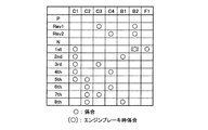
図2は、自動変速機10の複数のギヤ段(変速段)を成立させる際の係合装置(係合要素)の作動の組み合わせを説明する作動図表(係合作動表)であり、「○」はクラッチC1〜C4、ブレーキB1、B2の作動状態が係合状態を表し、「(○)」はエンジンブレーキ時のみ係合状態を表し、空欄は解放状態をそれぞれ表している。自動変速機10においては、クラッチC1〜C4、ブレーキB1、B2を選択的に係合することによりギヤ比γ(=入力軸24の回転速度/出力軸26の回転速度)が異なる複数のギヤ段例えば前進8段及び後進2段の多段変速が達成される。また、特に、第2ブレーキB2と並列に一方向クラッチF1が設けられていることから、第1速ギヤ段(1st)を成立させる際に、第2ブレーキB2はエンジンブレーキ時には係合させられる一方、駆動時には解放させられる。
FIG. 2 is an operation chart (engagement operation table) for explaining a combination of operations of engagement devices (engagement elements) when a plurality of gear stages (shift stages) of the
また、各ギヤ段毎に異なるギヤ比γは、第1遊星歯車装置14、第2遊星歯車装置18、第3遊星歯車装置20の各ギヤ比(=サンギヤの歯数/リングギヤの歯数)ρ1〜ρ3によって適宜定められる。また、図2から明らかなように、クラッチC1〜C4及びブレーキB1、B2の何れか2つを掴み替える所謂クラッチツウクラッチ変速により各ギヤ段の変速が行われており、変速制御が容易で変速ショックの発生が抑制される。
Further, the gear ratio γ that is different for each gear stage is the gear ratio of the first
また、クラッチC1〜C4、及びブレーキB1、B2(以下、特に区別しない場合は単にクラッチC、ブレーキBと表す)は、多板式のクラッチやブレーキなど油圧アクチュエータによって係合制御される油圧式摩擦係合装置(以下、係合装置という)であり、油圧制御回路40(図4参照)内のリニアソレノイドバルブSL1〜SL6の励磁、非励磁や電流制御により、係合、解放状態が切り換えられるとともに係合、解放時の過渡油圧などが制御される。 Further, the clutches C1 to C4 and the brakes B1 and B2 (hereinafter simply referred to as the clutch C and the brake B unless otherwise distinguished) are hydraulic friction members that are controlled by a hydraulic actuator such as a multi-plate clutch or a brake. This is a combination device (hereinafter referred to as an engagement device), and the engagement and release states are switched by the excitation, de-excitation, and current control of the linear solenoid valves SL1 to SL6 in the hydraulic control circuit 40 (see FIG. 4). In this case, the transient hydraulic pressure at the time of release is controlled.
図3は、第1変速部16及び第2変速部22の各回転要素の回転速度を直線で表すことができる共線図であり、下の横線が回転速度「0」を示し、上の横線が回転速度「1.0」すなわち入力軸24と同じ回転速度を示している。また、第1変速部16の各縦線は、左側から順番にサンギヤS1、リングギヤR1、キャリヤCA1を表しており、それ等の間隔は第1遊星歯車装置14のギヤ比ρ1に応じて定められる。第2変速部22の4本の縦線は、左側から順番に第1回転要素RM1(サンギヤS2)、第2回転要素RM2(キャリヤCA2及びキャリヤCA3)、第3回転要素RM3(リングギヤR2及びリングギヤR3)、第4回転要素RM4(サンギヤS3)を表しており、それ等の間隔は第2遊星歯車装置18のギヤ比ρ2及び第3遊星歯車装置20のギヤ比ρ3に応じて定められる。
FIG. 3 is a collinear diagram in which the rotational speeds of the rotating elements of the
そして、この共線図から明らかなように、第1クラッチC1及び一方向クラッチF1(或いはエンジンブレーキ時は第2ブレーキB2)が係合させられて、第4回転要素RM4が第1変速部16を介して入力軸24に対して減速回転させられるとともに、第2回転要素RM2が回転停止させられると、出力軸26に連結された第3回転要素RM3は「1st」で示す回転速度で回転させられ、最も大きいギヤ比(変速比)γ1の第1速ギヤ段(第1変速段)「1st」が成立させられる。他の変速段も同様にクラッチC及びブレーキBの何れかが選択的に係合されることにより成立させられる。
As is apparent from the alignment chart, the first clutch C1 and the one-way clutch F1 (or the second brake B2 when the engine is braked) are engaged, and the fourth rotation element RM4 is engaged with the
図4は、図1の自動変速機10などを含むエンジン28から駆動輪38までの動力伝達経路の概略構成を説明する図であると共に、その自動変速機10などを制御するために車両に設けられた制御系統の要部を説明するブロック線図である。電子制御装置100は、例えばCPU、RAM、ROM、入出力インターフェース等を備えた所謂マイクロコンピュータを含んで構成されており、CPUはRAMの一時記憶機能を利用しつつ予めROMに記憶されたプログラムに従って信号処理を行うことにより、基本的にはエンジン28の出力制御や自動変速機10のギヤ段を自動的に切り換える変速制御等を実行するようになっており、必要に応じてエンジン制御用やリニアソレノイドバルブSL1〜SL6を制御する変速制御用等に分けて構成される。
FIG. 4 is a diagram illustrating a schematic configuration of a power transmission path from the
図4において、車両に設けられたセンサやスイッチなどから、例えばクランク角度(位置)ACR(°)及びエンジン28の回転速度NEに対応するクランクポジションを検出するクランクポジションセンサ42、トルクコンバータ30のタービン軸の回転速度NTすなわち自動変速機10の入力軸24の回転速度NINを検出する入力側回転速度センサとしての入力回転速度センサ44、車速Vに対応する出力軸26の回転速度NOUTを検出する出力側回転速度センサとしての出力回転速度センサ46、車両の加速度(減速度)Gを検出するための加速度センサ50、油圧制御回路40内の作動油の温度であるAT油温TOILを検出するためのAT油温センサ52、エンジン28の吸入空気量QAIRを検出する吸入空気量センサ54、吸気配管56に設けられた電子スロットル弁58の開き角すなわちスロットル弁開度θTHを検出するスロットルポジションセンサ60、運転者の要求する車両駆動力(加速要求量)に応じて踏み込み操作される出力操作部材に相当するアクセルペダル62の操作量であるアクセル開度Accを検出するアクセル開度センサ64、常用ブレーキであるフットブレーキ66の操作の有無を表すブレーキ操作信号BONを検出するブレーキスイッチ68、手動変速操作装置としてのシフトレバー70のレバーポジション(操作位置)PSHを検出するシフトポジションセンサ72等から、クランク角度(位置)ACR(°)及びエンジン回転速度NE、入力回転速度NIN(=タービン回転速度NT)、出力回転速度NOUT、車速V、加速度(減速度)G、AT油温TOIL、吸入空気量QAIR、スロットル弁開度θTH、アクセル開度Acc、ブレーキ操作信号BON、レバーポジションPSHなどを表す信号が電子制御装置100に供給される。
4, the sensors and switches provided in the vehicle, for example, a crank angle (position) ACR (°) and the crank position sensor 42 detects a crank position corresponding to the rotational speed N E of the engine 28, the torque converter 30 An input rotational speed sensor 44 as an input side rotational speed sensor for detecting the rotational speed NT of the turbine shaft, that is, the rotational speed N IN of the input shaft 24 of the automatic transmission 10, and the rotational speed N OUT of the output shaft 26 corresponding to the vehicle speed V The output rotational speed sensor 46 serving as an output side rotational speed sensor for detecting the vehicle speed, the acceleration sensor 50 for detecting the acceleration (deceleration) G of the vehicle, and the AT oil temperature T OIL that is the temperature of the hydraulic oil in the hydraulic control circuit 40 AT oil temperature sensor 52 for detecting an intake air amount sensor for detecting an intake air quantity Q aIR of the engine 28 4, a throttle position sensor 60 for detecting angular i.e. throttle valve opening theta TH opening of the electronic throttle valve 58 provided in the intake pipe 56 is depression according to the vehicle driving force required by the driver (acceleration demand) Operation An accelerator opening sensor 64 that detects an accelerator opening Acc that is an operation amount of an accelerator pedal 62 corresponding to an output operation member, and a brake switch that detects a brake operation signal BON that indicates whether or not a foot brake 66 that is a service brake is operated. 68, a crank angle (position) ACR (°), an engine rotation speed N E , an input rotation speed N from a shift position sensor 72 for detecting a lever position (operation position) P SH of a
また、電子制御装置100からは、エンジン28の出力制御の為のエンジン出力制御指令信号SE、例えばアクセル開度Accに応じて電子スロットル弁58の開閉を制御するためのスロットルアクチュエータ74への駆動信号や燃料噴射装置76から噴射される燃料の量を制御するための噴射信号やイグナイタ78によるエンジン28の点火時期を制御するための点火時期信号などが出力されている。また、自動変速機10の変速制御の為の変速制御指令信号SP、例えば自動変速機10のギヤ段を切り換えるために油圧制御回路40内のリニアソレノイドバルブSL1〜SL6の励磁、非励磁などを制御するためのバルブ指令信号やライン油圧PLを制御するためのリニアソレノイドバルブSLTへの駆動信号などが出力されている。
Further, the
図5は、クラッチC及びブレーキBの各油圧アクチュエータ80、82、84、86、88、90の作動を制御するリニアソレノイドバルブSL1〜SL6等に関する回路図であって、油圧制御回路40の要部を示す回路図である。
FIG. 5 is a circuit diagram relating to the linear solenoid valves SL1 to SL6 for controlling the operation of the
図5において、クラッチC1、C2、及びブレーキB1、B2の各油圧アクチュエータ(油圧シリンダ)80、82、88、90には、油圧供給装置92から出力されたDレンジ圧(前進レンジ圧、前進油圧)PDがそれぞれリニアソレノイドバルブSL1、SL2、SL5、SL6により調圧されて供給され、クラッチC3及びC4の各油圧アクチュエータ84、86には、油圧供給装置92から出力された第1ライン油圧PL1がそれぞれリニアソレノイドバルブSL3、SL4により調圧されて供給されるようになっている。尚、ブレーキB2の油圧アクチュエータ90には、リニアソレノイドバルブSL6の出力油圧及びリバース圧(後進レンジ圧、後進油圧)PRのうち何れか供給された油圧がシャトル弁94を介して供給される。
In FIG. 5, the D range pressure (forward range pressure, forward hydraulic pressure) output from the hydraulic
油圧供給装置92は、エンジン28によって回転駆動される機械式のオイルポンプ48から発生する油圧を元圧として第1第1ライン油圧PL1を調圧する例えばリリーフ型のプライマリレギュレータバルブ(第1調圧弁)95、第1ライン油圧PL1の調圧のために第1調圧弁95から排出される油圧を元圧として第2ライン油圧PL2を調圧するセカンダリレギュレータバルブ(第2調圧弁)96、アクセル開度Acc或いはスロットル弁開度θTHで表されるエンジン負荷等に応じた第1ライン油圧PL1、第2ライン油圧PL2に調圧されるために第1調圧弁95及び第2調圧弁96へ信号圧PSLTを供給するリニアソレノイドバルブSLT、第1ライン油圧PL1を元圧として一定圧のモジュレータ油圧PMを調圧するモジュレータバルブ97、及びケーブルやリンクなどを介して機械的に連結されるシフトレバー70の操作に伴い機械的に作動させられて油路が切り換えられることにより入力された第1ライン油圧PL1をシフトレバー70が「D」ポジションへ操作されたときにはDレンジ圧PDとして出力し或いは「R」ポジションへ操作されたときにはリバース圧PRとして出力するマニュアルバルブ98等を備えており、第1ライン油圧PL1、第2ライン油圧PL2、モジュレータ油圧PM、Dレンジ圧PD、及びリバース圧PRを供給する。
The hydraulic
リニアソレノイドバルブSL1〜SL6は、基本的には何れも同じ構成で、電子制御装置100により独立に励磁、非励磁され、各油圧アクチュエータ80〜90の油圧が独立に調圧制御されてクラッチC1〜C4、ブレーキB1、B2の係合圧が制御される。そして、自動変速機10は、例えば図2の係合作動表に示すように予め定められた係合装置が係合されることによって各ギヤ段が成立させられる。また、自動変速機10の変速制御においては、例えば変速に関与するクラッチCやブレーキBの解放と係合とが同時に制御される所謂クラッチツウクラッチ変速が実行され、変速ショックを抑制するように解放過渡油圧と係合過渡油圧とが適切に制御される。
The linear solenoid valves SL1 to SL6 basically have the same configuration, and are excited and de-energized independently by the
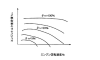
図6は、電子制御装置100による制御機能の要部を説明する機能ブロック線図である。図6において、エンジン出力制御手段102は、例えばスロットルアクチュエータ74により電子スロットル弁58を開閉制御する他、燃料噴射量制御のために燃料噴射装置76を制御し、点火時期制御のためにイグナイタ78を制御するエンジン出力制御指令信号SEを出力する。例えば、エンジン出力制御手段102は、図7に示すようなスロットル弁開度θTHをパラメータとしてエンジン回転速度NEとエンジントルク推定値TE0との予め実験的に求められて記憶された関係(エンジントルクマップ)から実際のエンジン回転速度NEに基づいて目標エンジントルクTE *が得られるスロットル弁開度θTHとなるようにスロットルアクチュエータ74により電子スロットル弁58を開閉制御する。上記目標エンジントルクTE *は、例えば運転者の加速要求量に対応するアクセル開度Accに基づいてそのアクセル開度Accが大きい程大きくされるように電子制御装置100により求められるものであり、ドライバー要求エンジントルクTEDEMに相当する。
FIG. 6 is a functional block diagram illustrating the main part of the control function of the
変速制御手段104は、例えば図8に示すような車速V及びアクセル開度Accを変数として予め記憶された関係(変速マップ、変速線図)から実際の車速V及びアクセル開度Accに基づいて変速判断を行い、自動変速機10の変速を実行すべきか否かを判断し、例えば自動変速機10の変速すべきギヤ段を判断し、その判断したギヤ段が得られるように自動変速機10の自動変速制御を実行する。このとき、変速制御手段104は、例えば図2に示す係合表に従ってギヤ段が達成されるように、自動変速機10の変速に関与する油圧式摩擦係合装置を係合及び/または解放させる変速制御指令信号SP(変速出力指令、油圧指令)を油圧制御回路40へ出力する。
The shift control means 104 shifts based on the actual vehicle speed V and the accelerator opening Acc from the relationship (shift map, shift diagram) stored in advance with the vehicle speed V and the accelerator opening Acc as variables, for example, as shown in FIG. A determination is made to determine whether or not a shift of the
その指令SPに従って、自動変速機10の変速が実行されるように油圧制御回路40内のリニアソレノイドバルブSL1〜SL6が駆動させられて、その変速に関与する油圧式摩擦係合装置の油圧アクチュエータ80〜90が作動させられる。
In accordance with the command SP, the linear solenoid valves SL1 to SL6 in the
図8の変速線図において、実線はアップシフトが判断されるための変速線(アップシフト線)であり、破線はダウンシフトが判断されるための変速線(ダウンシフト線)である。また、この図8の変速線図における変速線は、実際のアクセル開度Acc(%)を示す横線上において実際の車速Vが線を横切ったか否かすなわち変速線上の変速を実行すべき値(変速点車速)VSを越えたか否かを判断するためのものであり、この値VSすなわち変速点車速の連なりとして予め記憶されていることにもなる。尚、図8の変速線図は自動変速機10で変速が実行される第1速ギヤ段乃至第8速ギヤ段のうちで第1速ギヤ段乃至第6速ギヤ段における変速線が例示されている。
In the shift diagram of FIG. 8, a solid line is a shift line for determining an upshift (upshift line), and a broken line is a shift line for determining a downshift (downshift line). Further, the shift line in the shift diagram of FIG. 8 indicates whether or not the actual vehicle speed V crosses the line on the horizontal line indicating the actual accelerator opening Acc (%), that is, the value on which the shift on the shift line is to be executed ( This is for determining whether or not the shift point vehicle speed) VS has been exceeded, and is also stored in advance as a series of this value VS, that is, the shift point vehicle speed. The shift diagram of FIG. 8 illustrates shift lines in the first to sixth gears among the first to eighth gears at which the
例えば、変速制御手段104は、実際の車速Vが2速→3速アップシフトを実行すべき2速→3速アップシフト線を横切ったと判断した場合には、すなわち変速点車速V2−3を越えたと判断した場合には、ブレーキB1を解放させると共にクラッチC3を係合させる指令を油圧制御回路40に出力する、すなわち非励磁によってブレーキB1の係合油圧を排油(ドレン)させる指令をリニアソレノイドバルブSL5に出力すると共に、励磁によってクラッチC3の係合油圧を供給させる指令をリニアソレノイドバルブSL3に出力する。
For example, if the shift control means 104 determines that the actual vehicle speed V has crossed the 2nd speed → 3rd speed upshift line at which the 2nd speed → 3rd speed upshift is to be performed, that is, the speed change point vehicle speed V2-3 is exceeded. If it is determined that the brake B1 is released, a command to release the brake B1 and engage the clutch C3 is output to the
このように、変速制御手段104は、リニアソレノイドバルブSL1〜SL6の励磁、非励磁をそれぞれ制御することにより、リニアソレノイドバルブSL1〜SL6にそれぞれ対応するクラッチC1〜C4、及びブレーキB1、B2の係合、解放状態を切り換えて何れかのギヤ段を成立させる。また、変速制御手段104は、変速ショックの抑制と変速応答性の向上とが両立するように、タービン回転速度NT及び出力回転速度NOUTに基づいて変速過程における係合油圧(解放過渡油圧及び/または係合過渡油圧)をフィードバック制御したり或いは学習制御したりすることによりクラッチツウクラッチ変速を行う。 Thus, the shift control means 104 controls the excitation and non-excitation of the linear solenoid valves SL1 to SL6, respectively, thereby engaging the clutches C1 to C4 and the brakes B1 and B2 respectively corresponding to the linear solenoid valves SL1 to SL6. In this case, one of the gears is established by switching the release state. Further, the shift control means 104, as suppression of shift shock and the improvement in the shift response are compatible, engagement hydraulic pressure in the speed change process based on the turbine rotational speed N T and the output speed N OUT (disengagement transition hydraulic and The clutch-to-clutch shift is performed by feedback control or learning control of the engagement transient oil pressure).
ところで、本実施例の自動変速機10では、一方向クラッチF1の係合により成立させられる第1速ギヤ段において一方向クラッチF1が空転状態であるときには、例えば図9(a)の共線図に示す実線のようにクラッチC1のみが係合させられて一方向クラッチF1が未だ同期していない状態であるときには、自動変速機10内の動力伝達経路が解放されたすなわち自動変速機10内の動力伝達が遮断された所謂ニュートラル状態(中立状態)とされており、駆動輪38には駆動力が発生させられない。つまり、入力トルクに対して反力がない状態であるので出力トルクが零とされる。
By the way, in the
このような一方向クラッチF1が空転状態であるときに例えばアクセルオンとなる加速要求がなされると、エンジン回転速度NE(すなわちタービン回転速度NTに相当)の上昇に伴って第4回転要素RM4の回転速度が図9(a)の矢印に示す如く上昇させられ、駆動輪38の回転速度に拘束される第3回転要素RM3の回転速度を示す点Aを支点として(例えば点Aをシーソーの中心として)第2回転要素RM2の回転速度が低下させられて一方向クラッチF1が同期させられる回転方向に向かわさせられる。図9(a)の共線図に示す破線は一方向クラッチF1が同期した状態を示している。尚、図9(a)の共線図に示す一点鎖線はブレーキB1が係合させられて第2速ギヤ段が成立させられた状態を示している。
When an acceleration request for turning on the accelerator, for example, is made when the one-way clutch F1 is in the idling state, the fourth rotational element is increased with an increase in the engine rotational speed NE (ie, corresponding to the turbine rotational speed NT ). The rotational speed of the RM4 is increased as shown by the arrow in FIG. 9A, and the point A indicating the rotational speed of the third rotational element RM3 constrained by the rotational speed of the
そして、一方向クラッチF1が同期するときには、エンジントルクTEの伝達がステップ的に行われることによる急激なトルクの立ち上がりと駆動系のねじり振動に起因したトルク振動により同期ショックが発生することがある。また、加速要求がなされたとしても一方向クラッチF1が同期するまで駆動力が発生させられない。 When the one-way clutch F1 are synchronized, the synchronization shock may occur by the torque vibration caused by the rising and torsional vibrations in the drive system of the sudden torque due to the transmission of the engine torque T E is performed stepwise . Even if an acceleration request is made, no driving force is generated until the one-way clutch F1 is synchronized.
そこで、本実施例では駆動力レスポンスを向上しつつ、同期ショックを低減する為に、一方向クラッチF1の係合により成立させられる第1所定変速段としての第1速ギヤ段における一方向クラッチF1の空転状態にて加速要求がなされた際には、図9(b)に示すように、エンジン回転速度NEの上昇に伴って一方向クラッチF1が同期させられる回転方向に向かうことは継続させつつ本来なら一方向クラッチF1の空転状態が維持される第2所定変速段を成立させる為の摩擦係合装置にトルク容量を生じさせる。この第2所定変速段は、本実施例の自動変速機10においては、第1所定変速段(第1速ギヤ段)よりも自動変速機10の入力回転速度NINを低下させる高速段側の変速段であり、例えば第2速ギヤ段が想定される。従って、ここでは第2速ギヤ段を成立させる為のブレーキB1にトルク容量が生じさせられる。
Therefore, in the present embodiment, the one-way clutch F1 in the first speed gear stage as the first predetermined shift stage established by the engagement of the one-way clutch F1 in order to improve the driving force response and reduce the synchronous shock. when acceleration request at idle state has been made, as shown in FIG. 9 (b), to head in the direction of rotation the one-way clutch F1 is synchronized with increase in the engine rotational speed N E is allowed to continue On the other hand, a torque capacity is generated in the friction engagement device for establishing the second predetermined shift stage where the idling state of the one-way clutch F1 is maintained. The second predetermined gear stage in the
つまり、ブレーキB1を完全係合するのではなく半係合することで所定のトルク容量を生じさせて自動変速機10の出力トルク(アウトプットトルク)TOUTを発生させる。この際、ブレーキB1の半係合により一方向クラッチF1が同期させられる回転方向と反対方向に向かわさせられる力が働くので、一方向クラッチF1が同期させられる回転方向に向かうことが継続されるようにエンジントルクTEを加速要求量に応じた要求出力トルクとしてのドライバー要求エンジントルクTEDEMよりも所定値上昇させるエンジントルクアップを実行する。
That is, a predetermined torque capacity is generated by half-engaging the brake B1 rather than fully engaging, and the output torque (output torque) T OUT of the
以下、駆動力レスポンスを向上しつつ同期ショックを低減する為の電子制御装置100による制御機能を具体的に説明する。図6に戻り、電子制御装置100は、係合状態判定手段106と、加速要求判定手段108と、同期前制御手段110と、同期後制御手段112とを更に機能的に備えている。
Hereinafter, the control function by the
係合状態判定手段106は、一方向クラッチF1の係合により成立させられる第1速ギヤ段において一方向クラッチF1が係合状態とされているか否かを判定する。例えば、変速制御手段104は、変速マップから一方向クラッチF1でギヤ段を形成する第1速ギヤ段であるか否かを判断する。そして、係合状態判定手段106は、変速制御手段104により第1速ギヤ段であると判断された場合には、例えば実際のタービン回転速度NTが出力回転速度NOUTと第1速ギヤ段のギヤ比γ1とから一意的に決定される第1速ギヤ段におけるタービン回転速度NTの同期回転速度(=ギヤ比γ1×出力回転速度NOUT)に一致したか否かに基づいて、一方向クラッチF1が係合状態(同期状態)とされているか否かを判定する。尚、実回転速度と同期回転速度とが一致したか否かは、例えば実回転速度と同期回転速度とが一致したと判断される回転速度差以内になったことで判断される。 The engagement state determination means 106 determines whether or not the one-way clutch F1 is in the engagement state at the first gear that is established by the engagement of the one-way clutch F1. For example, the shift control means 104 determines from the shift map whether or not the first speed gear that forms the gear with the one-way clutch F1. Then, when the shift control means 104 determines that the engagement state determination means 106 is in the first speed gear stage, for example, the actual turbine rotational speed NT is set to the output rotational speed N OUT and the first speed gear stage. Based on whether or not it coincides with the synchronous rotational speed (= gear ratio γ1 × output rotational speed N OUT ) of the turbine rotational speed NT in the first speed gear stage uniquely determined from the gear ratio γ1 of It is determined whether or not the direction clutch F1 is in an engaged state (synchronized state). Note that whether or not the actual rotational speed and the synchronous rotational speed coincide with each other is determined by, for example, being within a rotational speed difference that is determined that the actual rotational speed and the synchronous rotational speed coincide with each other.
加速要求判定手段108は、車両に対する加速要求の有無を判定する。例えば、加速要求判定手段108は、アクセルペダル62の踏み増し操作が行われたか否か、例えばアクセルオフからアクセルオンとされたか否かに基づいて加速要求の有無を判定する。
The acceleration request determination means 108 determines whether or not there is an acceleration request for the vehicle. For example, the acceleration
同期前制御手段110は、変速制御手段104により一方向クラッチF1でギヤ段を形成する第1速ギヤ段であると判定されたときに、係合状態判定手段106により第1速ギヤ段において一方向クラッチF1が未だ係合状態(同期状態)とされていないと判定されすなわち一方向クラッチF1が空転状態であると判定され、且つ加速要求判定手段108により車両に対する加速要求が発生したと判定された際に、一方向クラッチF1の空転状態が維持される第2所定変速段として第2速ギヤ段を選択する。尚、この第2所定変速段は実際に形成される為に選択されるのではなく、あくまで一方向クラッチF1の空転状態において駆動力を発生させる為に見かけ上選択されるものである。見方を換えれば、同期前制御手段110は、一方向クラッチF1の空転状態において駆動力を発生させる為に係合力(トルク容量)を発生させる摩擦係合装置として一方向クラッチF1の空転状態が維持される第2速ギヤ段を成立させる為のブレーキB1を選択する。そして、同期前制御手段110は、その加速要求に伴って一方向クラッチF1が同期させられる回転方向に向かうことは継続させつつ第2速ギヤ段を成立させる為のブレーキB1にトルク容量を生じさせる。 The pre-synchronization control means 110 is determined by the engagement state determination means 106 at the first speed gear stage when the shift control means 104 determines that the first speed gear stage is formed by the one-way clutch F1. It is determined that the direction clutch F1 is not yet engaged (synchronized), that is, it is determined that the one-way clutch F1 is idling, and it is determined by the acceleration request determination means 108 that an acceleration request for the vehicle has occurred. The second speed gear stage is selected as the second predetermined speed stage in which the idling state of the one-way clutch F1 is maintained. The second predetermined shift speed is not selected to be actually formed, but is apparently selected to generate a driving force in the idling state of the one-way clutch F1. In other words, the pre-synchronization control means 110 maintains the idling state of the one-way clutch F1 as a friction engagement device that generates an engaging force (torque capacity) in order to generate a driving force in the idling state of the one-way clutch F1. The brake B1 for establishing the second gear to be established is selected. Then, the pre-synchronization control means 110 generates torque capacity in the brake B1 for establishing the second gear while continuing to move in the rotational direction in which the one-way clutch F1 is synchronized with the acceleration request. .
例えば、同期前制御手段110は、加速要求時の要求量(例えばアクセル開度Acc)が大きい程大きくされた自動変速機10の出力トルクの目標値(目標出力トルク)TOUT *が得られ且つ一方向クラッチF1を同期させる回転方向へ向かわせる為のタービン回転速度の目標値(目標タービン回転速度)NT *に沿ってタービン回転速度NTが上昇させられるように(すなわちエンジン回転速度NEが上昇させられるように)、ブレーキB1のトルク容量を発生させる指令を変速制御手段104へ出力し且つエンジントルクTEを加速要求時の要求量に応じたドライバー要求エンジントルクTEDEMよりも上昇させる指令をエンジン出力制御手段102へ出力する。
For example, the pre-synchronization control means 110 can obtain the target value (target output torque) T OUT * of the output torque of the
より具体的には、一方向クラッチF1の同期前の自動変速機10の出力トルクTOUTは、ブレーキB1のトルク容量(クラッチトルク)TCが大きくされる程大きくされ且つエンジントルクTEの上昇分(エンジントルクアップ)TUPが大きくされる程大きくされる第1の所定の関係式例えば次式(1)に示す関係式に基づいて算出される。
TOUT=0.07×(TEDEM+TUP)+3.11×TC ・・・(1)
More specifically, the output torque T OUT of the synchronizing front of the
T OUT = 0.07 × (T EDEM + T UP) + 3.11 × T C ··· (1)
また、タービン回転速度NTの上昇分(タービン回転速度アップ)ΔNTは、ブレーキB1のクラッチトルクTCが大きくされる程小さくされ且つエンジントルクアップTUPが大きくされる程大きくされる第2の所定の関係式例えば次式(2)に示す関係式に基づいて算出される。
ΔNT=6.39×TEDEM+6.39×TUP−11.1×TC ・・・(2)
尚、上記式(1)(2)内の0.07や3.11等の各数値は、例えばギヤ比や回転部材の慣性モーメントなどに基づいて車両や自動変速機10を含む動力伝達装置等で一意的に算出される定数である。
Further, the turbine rise (turbine speed-up) .DELTA.N T of the rotational speed N T, the second is larger as the clutch torque T C is small extent which is large and the engine torque increase T UP of the brake B1 is increased Is calculated based on a predetermined relational expression such as the relational expression shown in the following formula (2).
ΔN T = 6.39 × T EDEM + 6.39 × T UP -11.1 × T C ··· (2)
The numerical values such as 0.07 and 3.11 in the above formulas (1) and (2) are based on, for example, the gear ratio, the moment of inertia of the rotating member, etc., the power transmission device including the vehicle and the
そして、同期前制御手段110は、自動変速機10の出力トルクTOUTが運転者の操作に基づき求められた目標出力トルクTOUT *となるように前記(1)式及び前記(2)式に基づいてクラッチトルクTCを発生させ且つエンジントルクTEをドライバー要求エンジントルクTEDEMよりもエンジントルクアップTUPだけ上昇させる。すなわち、同期前制御手段110は、目標出力トルクTOUT *が得られ且つ目標タービン回転速度NT *に沿ってタービン回転速度NTが上昇させられるように、前記(1)、(2)式を用いてクラッチトルクTCとエンジントルクアップTUPとを決定し、ブレーキB1にクラッチトルクTCを発生させる指令及びドライバー要求エンジントルクTEDEMにエンジントルクアップTUPを加えたエンジントルクTEを発生させる指令を出力する。上記指令に従って、変速制御手段104はブレーキB1にクラッチトルクTCを発生させる為のバルブ指令信号(油圧指令値)を油圧制御回路40へ出力する。また、エンジン出力制御手段102は例えばドライバー要求エンジントルクTEDEMにエンジントルクアップTUPを加えたエンジントルクTEを発生する為の例えばスロットル弁開度θTHとするエンジン出力制御指令信号SEを出力する。
The
尚、目標出力トルクTOUT *は、一方向クラッチF1の同期後においては例えばアクセル開度Accが大きい程大きくされたドライバー要求エンジントルクTEDEMに対応する値(例えばドライバー要求エンジントルクTEDEMに第1速ギヤ段のギヤ比γ1を乗じた値)である。また、一方向クラッチF1の同期前においては例えばアクセルオンに対して駆動力の発生に遅れ感が生じ難く、駆動力の立ち上がりによるショックが抑制されるように同期後の目標出力トルクTOUT *に向かって漸増される値が設定される。 The target output torque T OUT * is the after synchronization of the one-way clutch F1 is the corresponding value (e.g., the driver required engine torque T EDEM the driver required engine torque T EDEM which is larger the larger the accelerator opening Acc e.g. (Multiplied by the gear ratio γ1 of the first gear). Further, before synchronization of the one-way clutch F1, for example, it is difficult to cause a delay in the generation of the driving force with respect to the accelerator on, and the target output torque T OUT * after the synchronization is suppressed so that the shock due to the rising of the driving force is suppressed. A value that is gradually increased is set.
また、目標タービン回転速度NT *は、一方向クラッチF1の同期後においては第1速ギヤ段におけるタービン回転速度NTの同期回転速度である。また、一方向クラッチF1の同期前においては例えば一方向クラッチF1の同期回転速度に向かう変化速度がブレーキB1のクラッチトルクTCを生じさせないときと比較して同等か或いは若干の遅れ程度となるように第1速ギヤ段におけるタービン回転速度NTの同期回転速度に向かって漸増される値が設定される。このように設定するのは、一方向クラッチF1を速やかに同期させて一方向クラッチF1の同期前から駆動力を発生させる為の制御を速やかに終了させたい為でもある。 Further, the target turbine rotational speed NT * is a synchronous rotational speed of the turbine rotational speed NT at the first speed gear stage after the synchronization of the one-way clutch F1. Also, as the rate of change toward the synchronous rotational speed of the pre-sync, for example one-way clutch F1 of the one-way clutch F1 is equal to or slightly delayed approximately as compared with when no cause clutch torque T C of the brake B1 A value that is gradually increased toward the synchronous rotational speed of the turbine rotational speed NT in the first speed gear stage is set. The reason for setting in this way is also to quickly end the control for generating the driving force before synchronizing the one-way clutch F1 by quickly synchronizing the one-way clutch F1.
同期後制御手段112は、一方向クラッチF1の同期後は、例えば係合状態判定手段106により第1速ギヤ段において一方向クラッチF1が係合状態(同期状態)とされたと判定された後は、同期前制御手段110による上述した制御に替えて、ドライバー要求エンジントルクTEDEMのみで目標出力トルクTOUT *が得られるように、ブレーキB1のクラッチトルクTCを減少させる指令を変速制御手段104へ出力し且つエンジントルクアップTUPを減少させる指令をエンジン出力制御手段102へ出力する。
After the synchronization of the one-way clutch F1, the
より具体的には、一方向クラッチF1の同期後の自動変速機10の出力トルクTOUTは、ブレーキB1のクラッチトルクTCが大きくされる程小さくされ且つエンジントルクアップTUPが大きくされる程大きくされる第3の所定の関係式例えば次式(3)に示す関係式に基づいて算出される。
TOUT=3.92×TEDEM+3.92×TUP−3.99×TC ・・・(3)
尚、上記式(3)内の3.92や3.99の各数値も、前記式(1)、(2)と同様に、例えばギヤ比や回転部材の慣性モーメントなどに基づいて車両や自動変速機10を含む動力伝達装置等で一意的に算出される定数である。
More specifically, the output torque T OUT of the
T OUT = 3.92 × T EDEM + 3.92 × T UP -3.99 × T C ··· (3)
It should be noted that the numerical values of 3.92 and 3.99 in the above formula (3) are similar to the above formulas (1) and (2), for example, based on the gear ratio, the moment of inertia of the rotating member, etc. The constant is uniquely calculated by a power transmission device including the
そして、同期後制御手段112は、前記(3)式における(3.92×TEDEM)の項で設定されるドライバー要求エンジントルクTEDEMに対応する目標出力トルクTOUT *が得られるように、(3.92×TUP−3.99×TC)の項を零としながら、すなわち(3.92×TUP=3.99×TC)の関係を維持しながら、言い換えればドライバーからは制御していないのと同じように見えるように、所定時間内にエンジントルクアップTUP及びブレーキB1のクラッチトルクTCを零に戻す。例えば、同期後制御手段112は、一方向クラッチF1の同期後の所定時間内にエンジントルクアップTUPを零に向かって逓減させる指令及びブレーキB1のクラッチトルクTCを前記(3)式に従って逓減させる指令を出力する。上記指令に従って、変速制御手段104はブレーキB1のクラッチトルクTCを逓減してブレーキB1を解放させる為のバルブ指令信号(油圧指令値)を油圧制御回路40へ出力する。また、エンジン出力制御手段102は例えばエンジントルクアップTUPを逓減させる為の例えばスロットル弁開度θTHとするエンジン出力制御指令信号SEを出力する。尚、上記所定時間は、一方向クラッチF1が同期した後には一方向クラッチF1の同期前から駆動力を発生させた一連の制御を速やかに終了させる為の予め求められた設定時間である。
Then, the
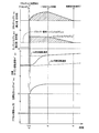
図10は、電子制御装置100の制御作動の要部すなわち駆動力レスポンスを向上しつつ同期ショックを低減する為の制御作動を説明するフローチャートであり、例えば数msec乃至数十msec程度の極めて短いサイクルタイムで繰り返し実行される。また、図11は、図10のフローチャートに示す制御作動を説明するタイムチャートである。
FIG. 10 is a flowchart for explaining the main part of the control operation of the
図10において、先ず、変速制御手段104に対応するステップ(以下、ステップを省略する)S10において、例えば変速マップから一方向クラッチF1でギヤ段を形成する第1速ギヤ段であるか否かがすなわち一方向クラッチF1の係合により成立させられる第1速ギヤ段であるか否かが判断される。第1速ギヤ段でないと判定されてこのS10の判断が否定される場合は本ルーチンが終了させられるが、第1速ギヤ段であると判定されてこのS10の判断が肯定される場合は係合状態判定手段106に対応するS20において、一方向クラッチF1の係合により成立させられる第1速ギヤ段において一方向クラッチF1が係合状態とされているか否かがすなわち一方向クラッチF1が同期しているか否かが判定される。 In FIG. 10, first, in step S10 corresponding to the shift control means 104 (hereinafter, step is omitted), for example, whether or not it is the first speed gear stage that forms a gear stage by the one-way clutch F1 from the shift map. That is, it is determined whether or not the first gear is established by engagement of the one-way clutch F1. If it is determined that the gear position is not the first gear and the determination in S10 is negative, this routine is terminated. However, if it is determined that the gear is the first gear and the determination in S10 is affirmative, the routine is terminated. In S20 corresponding to the engagement state determination means 106, it is determined whether or not the one-way clutch F1 is engaged in the first gear that is established by the engagement of the one-way clutch F1, that is, the one-way clutch F1 is synchronized. It is determined whether or not.
一方向クラッチF1が既に同期しており上記S20の判断が肯定される場合は本ルーチンが終了させられるが一方向クラッチF1が未だ同期しておらず上記S20の判断が否定される場合は加速要求判定手段108に対応するS30において、車両に対する加速要求が有るか否かが、例えばアクセルオフからアクセルオンとされたか否かに基づいて判定される。アクセルオンされておらずこのS30の判断が否定される場合は本ルーチンが終了させられるが、アクセルオンされてこのS30の判断が肯定される場合は同期前制御手段110に対応するS40において、一方向クラッチF1の空転状態において駆動力を発生させる為に係合力(トルク容量)を発生させる摩擦係合装置として一方向クラッチF1の空転状態が維持される第2速ギヤ段を成立させる為のブレーキB1が選択される(図11のt1時点)。 If the one-way clutch F1 is already synchronized and the determination in S20 is affirmed, this routine is terminated. If the one-way clutch F1 is not yet synchronized and the determination in S20 is negative, an acceleration request is made. In S30 corresponding to the determination means 108, it is determined whether or not there is an acceleration request for the vehicle, for example, based on whether or not the accelerator is turned off. If the accelerator is not turned on and the determination in S30 is negative, this routine is terminated. If the accelerator is turned on and the determination in S30 is affirmative, one of the routines in S40 corresponding to the pre-synchronization control means 110 is executed. Brake for establishing a second gear that maintains the idling state of the one-way clutch F1 as a friction engagement device that generates an engaging force (torque capacity) in order to generate a driving force in the idling state of the direction clutch F1. B1 is selected (t 1 point in FIG. 11).
次いで、同じく同期前制御手段110に対応するS50において、例えば図11に示すt3時点から立ち上がる目標出力トルクTOUT *が得られ且つ一方向クラッチF1を同期させる回転方向へ向かわせる為の例えば図11に示す目標タービン回転速度NT *に沿ってタービン回転速度NTが上昇させられるように、前述した式(1)、(2)を用いてクラッチトルクTCとエンジントルクアップTUPとが例えば図11に示すように決定される。そして、ブレーキB1にその決定されたクラッチトルクTCを発生させる指令が変速制御手段104へ出力される(図11のt2時点乃至t4時点)。及び、ドライバー要求エンジントルクTEDEMにエンジントルクアップTUPを加えたエンジントルクTEを発生させる指令がエンジン出力制御手段102へ出力される(図11のt1時点乃至t4時点)。
Then, similarly in S50 corresponding to the pre-synchronization control means 110, FIG example for directing the rotation direction, for example the target output torque T OUT * which rises from t 3 point shown in FIG. 11 to synchronize and one-way clutch F1 obtained 11 along the target turbine rotational speed N T * shown as turbine speed N T is raised, the aforementioned equations (1), and the clutch torque T C and the engine torque increase T uP with (2) For example, it is determined as shown in FIG. The command to generate a clutch torque T C which is the determined brake B1 is output to the
次いで、係合状態判定手段106に対応するS60において、一方向クラッチF1が同期したか否かが判定される。一方向クラッチF1が未だ同期しておらずこのS60の判断が否定される場合は前記S50に戻りこのS50以下が繰り返し実行される。一方、一方向クラッチF1が同期しこのS60の判断が肯定される場合は同期後制御手段112に対応するS70において、前記S50において実行されているブレーキB1にクラッチトルクTCを発生させ且つドライバー要求エンジントルクTEDEMにエンジントルクアップTUPを加えたエンジントルクTEを発生させる同期前制御に替えて、ドライバー要求エンジントルクTEDEMのみで目標出力トルクTOUT *が得られるように、ブレーキB1のクラッチトルクTCを減少させ且つエンジントルクアップTUPを減少させる同期後制御が実行される。例えば、一方向クラッチF1の同期後の所定時間内にエンジントルクアップTUPを零に向かって逓減させる指令がエンジン出力制御手段102へ出力され、且つブレーキB1のクラッチトルクTCを前述した式(3)に従って逓減させる指令が変速制御手段104へ出力される(図11のt4時点乃至t5時点)。
Next, in S60 corresponding to the engagement state determination means 106, it is determined whether or not the one-way clutch F1 is synchronized. If the one-way clutch F1 is not yet synchronized and the determination in S60 is negative, the process returns to S50, and S50 and subsequent steps are repeatedly executed. On the other hand, if the one-way clutch F1 in S60 determination of synchronization Sico is positive in S70 corresponding to the
上述のように、本実施例によれば、第1所定変速段(第1速ギヤ段)における一方向クラッチF1の空転状態にて例えばアクセルオンの加速要求が発生した場合には、同期前制御手段110により一方向クラッチF1の空転状態が維持される第2所定変速段(第2速ギヤ段)を成立させる為の摩擦係合装置であるブレーキB1にクラッチトルクTCが生じさせられるので、第1速ギヤ段における一方向クラッチF1の空転状態ではあるがすなわち一方向クラッチF1の同期前ではあるが自動変速機10の出力トルクTOUTが発生させられる。この際、同期前制御手段110により、第2速ギヤ段が成立させられわけではなく加速要求に伴って一方向クラッチF1が同期させられる回転方向に向かうことは継続させられるので、一方向クラッチF1は確実に同期させられて第1速ギヤ段が成立させられる。これにより、一方向クラッチF1の同期前に出力トルクTOUTが発生させられて駆動力レスポンスが向上する。加えて、一方向クラッチF1の同期時には既に出力トルクTOUTが発生していることからこの同期時に出力トルクTOUTの立ち上がりが生じず同期ショックが抑制される。
As described above, according to the present embodiment, the control before synchronization is performed when, for example, an accelerator-on acceleration request is generated in the idling state of the one-way clutch F1 at the first predetermined gear (first gear). the clutch torque T C of the brake B1 is frictional engagement devices to establish the second predetermined shift stage idle state of the one-way clutch F1 is maintained (second gear stage) by
別の見方をすれば、第2速ギヤ段を成立させる為のブレーキB1にクラッチトルクTCを生じさせることで、単に加速要求に伴って一方向クラッチF1が同期させられる回転方向へ向かうことに比較して緩やかな速度で同期させられる回転方向へ向かわせることもでき、それにより同期ショックを抑制することが可能になる。この際、単に加速要求に伴って一方向クラッチF1が同期させられることに比較して一方向クラッチF1の同期は遅延させられるが、同期前から出力トルクTOUTが発生させられていることから、駆動力レスポンスは向上させられるものの低下させられることはない。 Viewed another way, by causing the clutch torque T C of the brake B1 for establishing the second speed gear, only that the one-way clutch F1 in accordance with the acceleration request is directed to the direction of rotation are synchronized In comparison, the direction of rotation can be made to synchronize at a moderate speed, thereby making it possible to suppress a synchronous shock. At this time, although the synchronization of the one-way clutch F1 is delayed as compared with the case where the one-way clutch F1 is merely synchronized with the acceleration request, the output torque T OUT is generated before the synchronization. Although the driving force response is improved, it is not reduced.
従って、一方向クラッチF1の係合により成立させられる変速段において一方向クラッチF1が空転状態であるときに加速要求がなされた際に、駆動力レスポンスの向上と同期ショックの低減とを両立することができる。 Therefore, when the acceleration request is made when the one-way clutch F1 is in the idling state at the shift stage established by the engagement of the one-way clutch F1, both improvement of the driving force response and reduction of the synchronous shock are achieved. Can do.
また、本実施例によれば、同期前制御手段110は、加速要求時の要求量が大きい程大きくされた目標出力トルクTOUT *が得られ且つ一方向クラッチF1を同期させる回転方向へ向かわせる為の目標タービン回転速度NT *に沿ってタービン回転速度NTが上昇させられるように、第2速ギヤ段を成立させる為のブレーキB1のクラッチトルクTCを発生させ且つエンジントルクTEを加速要求時の要求量に応じたドライバー要求エンジントルクTEDEMよりも上昇させるので、一方向クラッチF1の同期前から自動変速機10の出力トルクTOUTが適切に発生させられ、加えて一方向クラッチF1が確実に同期させられる。
In addition, according to the present embodiment, the pre-synchronization control means 110 obtains a larger target output torque T OUT * as the required amount at the time of acceleration request is larger, and directs the one-way clutch F1 in the rotational direction to synchronize. since along the target turbine rotational speed N T * of such turbine speed N T is raised, the clutch torque T C is generated and the engine torque T E of the brake B1 for establishing the second-speed gear stage Since it is higher than the driver required engine torque TEDEM corresponding to the required amount at the time of acceleration request, the output torque T OUT of the
また、本実施例によれば、同期前制御手段110は、自動変速機10の出力トルクTOUTが運転者の操作に基づき求められた目標出力トルクTOUT *となるように前記(1)式及び前記(2)式に基づいてブレーキB1のクラッチトルクTCを発生させ且つエンジントルクTEをドライバー要求エンジントルクTEDEMよりもエンジントルクアップTUPだけ上昇させるので、目標出力トルクTOUT *となる出力トルクTOUTが得られ且つタービン回転速度NTが目標タービン回転速度NT *に沿って上昇させられるように、前記(1)及び(2)式に基づいて第2速ギヤ段を成立させる為のブレーキB1のクラッチトルクTCとエンジントルクアップTUPとが算出され、その算出結果に基づいてブレーキB1の作動とエンジントルクとが適切に制御される。
In addition, according to the present embodiment, the
また、本実施例によれば、同期後制御手段112は、一方向クラッチF1の同期後は、同期前制御手段110による制御に替えて、ドライバー要求エンジントルクTEDEMのみで目標出力トルクTOUT *が得られるように、第2速ギヤ段を成立させる為のブレーキB1のクラッチトルクTCを減少させ且つエンジントルクアップTUPを減少させるので、一方向クラッチF1の同期後は同期前制御手段110により発生させられたブレーキB1のクラッチトルクTCやエンジントルクアップTUPが速やかに解除させられ、ドライバー要求エンジントルクTEDEMのみで目標出力トルクTOUT *を得るという通常状態の制御に速やかに戻される。 Further, according to the present embodiment, after synchronization of the one-way clutch F1, the post-synchronization control means 112 is replaced with the control by the pre-synchronization control means 110, and only the driver requested engine torque T EDEM is used as the target output torque T OUT * as can be obtained, because it reduces the and engine torque increase T uP decreases the clutch torque T C of the brake B1 for establishing the second speed gear position, after synchronization of the one-way clutch F1 is pre-synchronization control means 110 The brake torque T C and the engine torque increase T UP generated by the brake B1 are promptly released, and the control returns to the normal state in which the target output torque T OUT * is obtained only by the driver request engine torque T EDEM. It is.
また、本実施例によれば、同期後制御手段112は、一方向クラッチF1の同期後の所定時間内にエンジントルクアップTUPを零に向かって逓減させ、第2速ギヤ段を成立させる為のブレーキB1のクラッチトルクTCを前記(3)式に従って逓減させるので、前記(3)式に基づいて一方向クラッチF1の同期後の所定時間内に同期前制御手段110により発生させられたブレーキB1のクラッチトルクTCやエンジントルクアップTUPが解除させられる。
In addition, according to the present embodiment, the post-synchronization control means 112 gradually decreases the engine torque increase T UP toward zero within a predetermined time after the synchronization of the one-way clutch F1 to establish the second speed gear stage. since the clutch torque T C of the brake B1 is decreasing in accordance with the equation (3), wherein (3) brake that is is generated by the
以上、本発明の実施例を図面に基づいて詳細に説明したが、本発明はその他の態様においても適用される。 As mentioned above, although the Example of this invention was described in detail based on drawing, this invention is applied also in another aspect.
例えば、前述の実施例では、第1所定変速段は第1速ギヤ段であり、第2所定変速段は第2速ギヤ段であったが、例えば第1所定変速段は一方向クラッチの係合により成立させられるギヤ段であれば良く、また第2所定変速段は一方向クラッチの空転状態を維持するギヤ段であれば良く、車両用自動変速機のギヤ段の構成によって各々1つ乃至複数の種々のギヤ段が適用され得る。 For example, in the above-described embodiment, the first predetermined gear stage is the first speed gear stage and the second predetermined gear stage is the second speed gear stage. For example, the first predetermined gear stage is the engagement of the one-way clutch. The second predetermined gear stage may be a gear stage that maintains the idling state of the one-way clutch, and one or more gear stages may be set depending on the configuration of the gear stage of the vehicle automatic transmission. A plurality of different gear stages can be applied.
また、前述の実施例では、加速要求としてアクセルオフからのアクセルオンを例示したが、例えばアクセルペダル62の一定踏込状態からのアクセルペダル62の踏み増しであっても良いし、良く知られたクルーズコントロール制御における加速要求等であっても良い。
Further, in the above-described embodiment, the accelerator-on from the accelerator-off is exemplified as the acceleration request. However, for example, the
なお、上述したのはあくまでも一実施形態であり、本発明は当業者の知識に基づいて種々の変更、改良を加えた態様で実施することができる。 The above description is only an embodiment, and the present invention can be implemented in variously modified and improved forms based on the knowledge of those skilled in the art.
10:車両用自動変速機
28:エンジン(駆動力源)
38:駆動輪
100:電子制御装置
106:係合状態判定手段
108:加速要求判定手段
110:同期前制御手段
112:同期後制御手段
B1、B2:ブレーキ(摩擦係合装置)
C1〜C4:クラッチ(摩擦係合装置)
F1:一方向クラッチ
10: Vehicle automatic transmission 28: Engine (drive power source)
38: Drive wheel 100: Electronic control unit 106: Engagement state determination unit 108: Acceleration request determination unit 110: Pre-synchronization control unit 112: Post-synchronization control unit B1, B2: Brake (friction engagement device)
C1 to C4: Clutch (friction engagement device)
F1: One-way clutch
Claims (5)
前記一方向クラッチの係合により成立させられる第1所定変速段において該一方向クラッチが係合状態とされているか否かを判定する係合状態判定手段と、
車両に対する加速要求の有無を判定する加速要求判定手段と、
前記第1所定変速段における前記一方向クラッチの空転状態にて前記加速要求が発生した際に、該加速要求に伴って該一方向クラッチが同期させられる回転方向に向かうことは継続させつつ該一方向クラッチの空転状態が維持される第2所定変速段を成立させる為の摩擦係合装置にトルク容量を生じさせる同期前制御手段と
を、含むことを特徴とする車両用自動変速機の制御装置。 A control device for an automatic transmission for a vehicle in which a plurality of shift stages having different gear ratios are established by selectively engaging any one of a plurality of friction engagement devices and a one-way clutch,
Engagement state determination means for determining whether or not the one-way clutch is in an engagement state at a first predetermined shift stage established by engagement of the one-way clutch;
Acceleration request determination means for determining whether or not there is an acceleration request for the vehicle;
When the acceleration request is generated in the idling state of the one-way clutch at the first predetermined shift stage, the one-way clutch is continuously moved in the rotational direction in which the one-way clutch is synchronized with the acceleration request. And a pre-synchronization control means for generating a torque capacity in the friction engagement device for establishing the second predetermined shift stage in which the idling state of the direction clutch is maintained. .
前記一方向クラッチは、前記加速要求に伴って前記車両用自動変速機の入力回転速度が上昇させられることで同期させられる回転方向に向かい、
前記第2所定変速段は、前記第1所定変速段よりも前記車両用自動変速機の入力回転速度を低下させる高速段側の変速段であり、
前記同期前制御手段は、前記加速要求時の要求量が大きい程大きくされた前記車両用自動変速機の出力トルクの目標値が得られ且つ前記一方向クラッチを同期させる回転方向へ向かわせる為の前記車両用自動変速機の入力回転速度の目標値に沿って該入力回転速度が上昇させられるように、前記第2所定変速段を成立させる為の摩擦係合装置のトルク容量を発生させ且つ前記駆動力源の出力トルクを前記加速要求時の要求量に応じた要求出力トルクよりも上昇させることを特徴とする請求項1に記載の車両用自動変速機の制御装置。 The automatic transmission for a vehicle is a power transmission device that transmits power output from a driving force source to a driving wheel side,
The one-way clutch is directed in a rotational direction that is synchronized by increasing an input rotational speed of the vehicle automatic transmission in accordance with the acceleration request,
The second predetermined shift stage is a high-speed stage shift stage that reduces the input rotational speed of the vehicle automatic transmission from the first predetermined shift stage.
The pre-synchronization control means obtains a target value of the output torque of the vehicular automatic transmission that is increased as the required amount at the time of the acceleration request is larger, and is directed to a rotational direction that synchronizes the one-way clutch. Generating a torque capacity of the friction engagement device for establishing the second predetermined shift stage so that the input rotational speed is increased along a target value of the input rotational speed of the vehicle automatic transmission; and 2. The control device for an automatic transmission for a vehicle according to claim 1, wherein the output torque of the driving force source is increased more than the required output torque corresponding to the required amount at the time of the acceleration request.
前記車両用自動変速機の入力回転速度の上昇分は、前記第2所定変速段を成立させる為の摩擦係合装置のトルク容量が大きくされる程小さくされ且つ前記駆動力源の出力トルクの上昇分が大きくされる程大きくされる第2の所定の関係式に基づいて算出されるものであり、
前記同期前制御手段は、前記車両用自動変速機の出力トルクが運転者の操作に基づき求められた目標値となるように前記第1の所定の関係式及び前記第2の所定の関係式に基づいて前記トルク容量を発生させ且つ前記駆動力源の出力トルクを上昇させることを特徴とする請求項2に記載の車両用自動変速機の制御装置。 The output torque of the vehicle automatic transmission is increased as the torque capacity of the friction engagement device for establishing the second predetermined shift stage is increased, and the increase in the output torque of the driving force source is increased. Calculated based on a first predetermined relational expression that is increased as
The increase in the input rotational speed of the automatic transmission for the vehicle is reduced as the torque capacity of the friction engagement device for establishing the second predetermined shift speed is increased, and the output torque of the driving force source is increased. It is calculated based on a second predetermined relational expression that is increased as the minute is increased,
The pre-synchronization control means sets the first predetermined relational expression and the second predetermined relational expression so that the output torque of the vehicle automatic transmission becomes a target value obtained based on a driver's operation. 3. The control apparatus for an automatic transmission for a vehicle according to claim 2, wherein the torque capacity is generated based on the output torque and the output torque of the driving force source is increased.
前記同期後制御手段は、前記一方向クラッチの同期後の所定時間内に前記駆動力源の出力トルクの上昇分を零に向かって逓減させ、前記第2所定変速段を成立させる為の摩擦係合装置のトルク容量を前記第3の所定の関係式に従って逓減させることを特徴とする請求項4に記載の車両用自動変速機の制御装置。 The output torque of the vehicular automatic transmission after synchronization of the one-way clutch is reduced as the torque capacity of the friction engagement device for establishing the second predetermined speed is increased, and the driving force source It is calculated based on a third predetermined relational expression that is increased as the increase in output torque is increased,
The post-synchronization control means reduces the increase in the output torque of the driving force source toward zero within a predetermined time after the synchronization of the one-way clutch, and establishes the second predetermined shift stage. 5. The control device for an automatic transmission for a vehicle according to claim 4, wherein the torque capacity of the combined device is gradually decreased according to the third predetermined relational expression.
Priority Applications (5)
| Application Number | Priority Date | Filing Date | Title |
|---|---|---|---|
| JP2008200088A JP4656206B2 (en) | 2008-08-01 | 2008-08-01 | Control device for automatic transmission for vehicle |
| EP09786027.4A EP2321559B1 (en) | 2008-08-01 | 2009-07-20 | Control apparatus and control method for vehicle automatic transmission |
| US13/055,777 US8725367B2 (en) | 2008-08-01 | 2009-07-20 | Control apparatus and control method for vehicle automatic transmission |
| CN200980130321.0A CN102112784B (en) | 2008-08-01 | 2009-07-20 | Control apparatus and control method for vehicle automatic transmission |
| PCT/IB2009/006286 WO2010013104A1 (en) | 2008-08-01 | 2009-07-20 | Control apparatus and control method for vehicle automatic transmission |
Applications Claiming Priority (1)
| Application Number | Priority Date | Filing Date | Title |
|---|---|---|---|
| JP2008200088A JP4656206B2 (en) | 2008-08-01 | 2008-08-01 | Control device for automatic transmission for vehicle |
Publications (2)
| Publication Number | Publication Date |
|---|---|
| JP2010038210A true JP2010038210A (en) | 2010-02-18 |
| JP4656206B2 JP4656206B2 (en) | 2011-03-23 |
Family
ID=41165547
Family Applications (1)
| Application Number | Title | Priority Date | Filing Date |
|---|---|---|---|
| JP2008200088A Expired - Fee Related JP4656206B2 (en) | 2008-08-01 | 2008-08-01 | Control device for automatic transmission for vehicle |
Country Status (5)
| Country | Link |
|---|---|
| US (1) | US8725367B2 (en) |
| EP (1) | EP2321559B1 (en) |
| JP (1) | JP4656206B2 (en) |
| CN (1) | CN102112784B (en) |
| WO (1) | WO2010013104A1 (en) |
Families Citing this family (11)
| Publication number | Priority date | Publication date | Assignee | Title |
|---|---|---|---|---|
| CN103562042B (en) * | 2011-06-02 | 2016-04-06 | 本田技研工业株式会社 | Drive system |
| CN102606726B (en) * | 2012-03-29 | 2015-01-07 | 浙江吉利汽车研究院有限公司 | Neutral gear pre-engaging control device of automobile synchronizer |
| US8443688B1 (en) * | 2012-07-26 | 2013-05-21 | GM Global Technology Operations LLC | Method of learning an initial capacity point of a clutch in a dual clutch transmission |
| KR101593830B1 (en) * | 2014-10-14 | 2016-02-15 | 현대오트론 주식회사 | Method and apparatus for estimating engine power |
| JP6399033B2 (en) * | 2016-04-27 | 2018-10-03 | トヨタ自動車株式会社 | Control device for automatic transmission |
| JP6673261B2 (en) * | 2017-02-24 | 2020-03-25 | トヨタ自動車株式会社 | Vehicle speed change control device |
| JP6791044B2 (en) * | 2017-07-14 | 2020-11-25 | トヨタ自動車株式会社 | Control device for vehicle power distribution device |
| CN111279093B (en) * | 2017-10-31 | 2021-10-12 | 本田技研工业株式会社 | Clutch control device |
| EP3699449B1 (en) | 2017-10-31 | 2022-07-20 | Honda Motor Co., Ltd. | Clutch control device |
| JP6922799B2 (en) * | 2018-03-15 | 2021-08-18 | トヨタ自動車株式会社 | Vehicle control device |
| CN111594435A (en) * | 2020-04-17 | 2020-08-28 | 科力远混合动力技术有限公司 | Starting control method of hybrid power gearbox vane pump |
Citations (4)
| Publication number | Priority date | Publication date | Assignee | Title |
|---|---|---|---|---|
| JPH051589A (en) * | 1991-06-20 | 1993-01-08 | Toyota Motor Corp | Controller of automatic transmission for vehicle |
| JPH10288059A (en) * | 1997-04-15 | 1998-10-27 | Toyota Motor Corp | Control device for vehicle prime mover |
| JPH10324178A (en) * | 1998-06-05 | 1998-12-08 | Nissan Motor Co Ltd | One-way clutch engagement shock prevention device for automatic transmission |
| JP2008157387A (en) * | 2006-12-25 | 2008-07-10 | Toyota Motor Corp | Power train control device and method, program for actualizing the method, and recording medium recording the program |
Family Cites Families (20)
| Publication number | Priority date | Publication date | Assignee | Title |
|---|---|---|---|---|
| US4884667A (en) * | 1987-07-22 | 1989-12-05 | Isuzu Motors Ltd. | Automatic change gear control means |
| JPH0684135B2 (en) * | 1987-09-29 | 1994-10-26 | ジャトコ株式会社 | Control device for engine / automatic transmission drive system |
| JP3429588B2 (en) * | 1995-01-10 | 2003-07-22 | 三菱電機株式会社 | Transmission control device for automatic transmission |
| JPH08246913A (en) * | 1995-03-03 | 1996-09-24 | Toyota Motor Corp | Control device of automatic transmission |
| JP3191683B2 (en) * | 1996-06-11 | 2001-07-23 | アイシン・エィ・ダブリュ株式会社 | Transmission control device for automatic transmission |
| JP3194379B2 (en) * | 1999-04-30 | 2001-07-30 | トヨタ自動車株式会社 | Cooperative control device for prime mover and automatic transmission |
| JP3427792B2 (en) * | 1999-08-27 | 2003-07-22 | トヨタ自動車株式会社 | Control device for automatic transmission for vehicles |
| JP2001330140A (en) * | 2000-05-22 | 2001-11-30 | Toyota Motor Corp | Control device for vehicular clutch |
| JP4770021B2 (en) * | 2000-12-28 | 2011-09-07 | アイシン・エィ・ダブリュ株式会社 | Shift control device for automatic transmission |
| JP3901010B2 (en) * | 2002-05-17 | 2007-04-04 | アイシン・エィ・ダブリュ株式会社 | Shift control device for automatic transmission |
| JP2005009395A (en) | 2003-06-18 | 2005-01-13 | Toyota Motor Corp | Vehicular control device |
| JP4289176B2 (en) * | 2004-03-01 | 2009-07-01 | トヨタ自動車株式会社 | Vehicle shift control device |
| JP4432861B2 (en) * | 2005-08-22 | 2010-03-17 | トヨタ自動車株式会社 | Vehicle driving force control device |
| DE102006035482B4 (en) * | 2005-12-06 | 2021-08-05 | Toyota Jidosha Kabushiki Kaisha | Shift control device and shift control method of a vehicle automatic transmission |
| DE102006022171A1 (en) * | 2006-05-12 | 2007-11-15 | Zf Friedrichshafen Ag | Method for determining the mass of a motor vehicle |
| JP2008064176A (en) * | 2006-09-06 | 2008-03-21 | Toyota Motor Corp | Vehicular control device |
| JP4162024B2 (en) * | 2006-09-13 | 2008-10-08 | トヨタ自動車株式会社 | Control device for automatic transmission for vehicle |
| JP4325654B2 (en) * | 2006-09-15 | 2009-09-02 | トヨタ自動車株式会社 | Control device for automatic transmission |
| JP4360421B2 (en) * | 2007-05-15 | 2009-11-11 | トヨタ自動車株式会社 | Shift control device for automatic transmission |
| US8478498B2 (en) * | 2008-09-09 | 2013-07-02 | GM Global Technology Operations LLC | Engine power management for a selectable one-way clutch or mechanical diode in automatic transmissions |
-
2008
- 2008-08-01 JP JP2008200088A patent/JP4656206B2/en not_active Expired - Fee Related
-
2009
- 2009-07-20 CN CN200980130321.0A patent/CN102112784B/en not_active Expired - Fee Related
- 2009-07-20 WO PCT/IB2009/006286 patent/WO2010013104A1/en active Application Filing
- 2009-07-20 US US13/055,777 patent/US8725367B2/en active Active
- 2009-07-20 EP EP09786027.4A patent/EP2321559B1/en not_active Not-in-force
Patent Citations (4)
| Publication number | Priority date | Publication date | Assignee | Title |
|---|---|---|---|---|
| JPH051589A (en) * | 1991-06-20 | 1993-01-08 | Toyota Motor Corp | Controller of automatic transmission for vehicle |
| JPH10288059A (en) * | 1997-04-15 | 1998-10-27 | Toyota Motor Corp | Control device for vehicle prime mover |
| JPH10324178A (en) * | 1998-06-05 | 1998-12-08 | Nissan Motor Co Ltd | One-way clutch engagement shock prevention device for automatic transmission |
| JP2008157387A (en) * | 2006-12-25 | 2008-07-10 | Toyota Motor Corp | Power train control device and method, program for actualizing the method, and recording medium recording the program |
Also Published As
| Publication number | Publication date |
|---|---|
| EP2321559B1 (en) | 2019-02-27 |
| US8725367B2 (en) | 2014-05-13 |
| EP2321559A1 (en) | 2011-05-18 |
| US20110125375A1 (en) | 2011-05-26 |
| CN102112784B (en) | 2014-11-26 |
| CN102112784A (en) | 2011-06-29 |
| JP4656206B2 (en) | 2011-03-23 |
| WO2010013104A8 (en) | 2011-02-17 |
| WO2010013104A1 (en) | 2010-02-04 |
Similar Documents
| Publication | Publication Date | Title |
|---|---|---|
| JP4656206B2 (en) | Control device for automatic transmission for vehicle | |
| JP4353148B2 (en) | Control device for automatic transmission | |
| JP4396631B2 (en) | Shift control device for automatic transmission for vehicle | |
| JP5338982B2 (en) | Control device for automatic transmission for vehicle | |
| JP2007040132A (en) | Gear change control device for vehicular automatic transmission | |
| US10100925B2 (en) | Control device for automatic transmission of vehicle and control method for automatic transmission of vehicle | |
| JP2008169874A (en) | Control device for vehicle drive mechanism | |
| JP4162024B2 (en) | Control device for automatic transmission for vehicle | |
| JP4265539B2 (en) | Shift control device for vehicle drive device | |
| JPWO2010079622A1 (en) | Control device for vehicle hydraulic control circuit | |
| JP4690278B2 (en) | Shift control device for automatic transmission | |
| JP4923547B2 (en) | Shift control device for automatic transmission for vehicle | |
| JP2010115984A (en) | Controller for vehicle power transmission | |
| JP2013029154A (en) | Hydraulic control device of vehicle automatic transmission | |
| JP6020430B2 (en) | Vehicle control device | |
| JP2010203590A (en) | Control device of driving device for vehicle | |
| JP2008039114A (en) | Control device for automatic transmission for vehicle | |
| JP5093072B2 (en) | Control device for automatic transmission for vehicle | |
| JP5212127B2 (en) | Control device for automatic transmission for vehicle | |
| JP5035221B2 (en) | Shift control device for automatic transmission | |
| JP5299310B2 (en) | Control device for automatic transmission | |
| JP2010175062A (en) | Control device of power transmission device for vehicle | |
| JP6003615B2 (en) | Shift control device for automatic transmission for vehicle | |
| JP2019095014A (en) | Control device of vehicle | |
| JP2006083970A (en) | Shift control device for automatic transmission for vehicle |
Legal Events
| Date | Code | Title | Description |
|---|---|---|---|
| A131 | Notification of reasons for refusal |
Free format text: JAPANESE INTERMEDIATE CODE: A131 Effective date: 20100413 |
|
| A977 | Report on retrieval |
Free format text: JAPANESE INTERMEDIATE CODE: A971007 Effective date: 20100415 |
|
| A521 | Request for written amendment filed |
Free format text: JAPANESE INTERMEDIATE CODE: A523 Effective date: 20100614 |
|
| TRDD | Decision of grant or rejection written | ||
| A01 | Written decision to grant a patent or to grant a registration (utility model) |
Free format text: JAPANESE INTERMEDIATE CODE: A01 Effective date: 20101130 |
|
| A01 | Written decision to grant a patent or to grant a registration (utility model) |
Free format text: JAPANESE INTERMEDIATE CODE: A01 |
|
| A61 | First payment of annual fees (during grant procedure) |
Free format text: JAPANESE INTERMEDIATE CODE: A61 Effective date: 20101213 |
|
| FPAY | Renewal fee payment (event date is renewal date of database) |
Free format text: PAYMENT UNTIL: 20140107 Year of fee payment: 3 |
|
| R151 | Written notification of patent or utility model registration |
Ref document number: 4656206 Country of ref document: JP Free format text: JAPANESE INTERMEDIATE CODE: R151 |
|
| FPAY | Renewal fee payment (event date is renewal date of database) |
Free format text: PAYMENT UNTIL: 20140107 Year of fee payment: 3 |
|
| LAPS | Cancellation because of no payment of annual fees |