JP2010037013A - Carrying/straightening device and inspection device for screw and washer assembly - Google Patents
Carrying/straightening device and inspection device for screw and washer assembly Download PDFInfo
- Publication number
- JP2010037013A JP2010037013A JP2008199246A JP2008199246A JP2010037013A JP 2010037013 A JP2010037013 A JP 2010037013A JP 2008199246 A JP2008199246 A JP 2008199246A JP 2008199246 A JP2008199246 A JP 2008199246A JP 2010037013 A JP2010037013 A JP 2010037013A
- Authority
- JP
- Japan
- Prior art keywords
- screw
- washer
- guide
- built
- head
- Prior art date
- Legal status (The legal status is an assumption and is not a legal conclusion. Google has not performed a legal analysis and makes no representation as to the accuracy of the status listed.)
- Granted
Links
- 238000007689 inspection Methods 0.000 title claims description 73
- 230000002093 peripheral effect Effects 0.000 claims description 9
- 239000000463 material Substances 0.000 claims description 2
- 230000003247 decreasing effect Effects 0.000 abstract 1
- 230000002950 deficient Effects 0.000 description 7
- 230000007423 decrease Effects 0.000 description 4
- 230000007704 transition Effects 0.000 description 3
- 238000009434 installation Methods 0.000 description 2
- 238000004519 manufacturing process Methods 0.000 description 2
- 238000003825 pressing Methods 0.000 description 2
- 230000006866 deterioration Effects 0.000 description 1
- 238000000034 method Methods 0.000 description 1
- 238000007747 plating Methods 0.000 description 1
- 208000026438 poor feeding Diseases 0.000 description 1
- 238000005096 rolling process Methods 0.000 description 1
- 239000000725 suspension Substances 0.000 description 1
Images


Abstract
Description
この発明は、座金組み込みねじ(セムスねじと称されている)を吊り下げて搬送し、その搬送の途中に吊り下げ姿勢を安定させる搬送・矯正装置と、その装置を利用して良否検査の検査精度を向上させた検査装置に関する。 The present invention suspends and conveys a washer built-in screw (referred to as a Semus screw), conveys it, and stabilizes the suspended posture in the middle of the conveyance. The present invention relates to an inspection apparatus with improved accuracy.
首記の座金組み込みねじは、ねじ外径よりも穴径の小さい座金を、ねじを転造する前に首下部分に組み込み、その後にねじを転造することで座金が外れないようにしたものである。座金は、1枚のばね座金や1枚の平座金、各1枚のばね座金と平座金、或いは、歯付き座金が用いられている。 The washer built-in screw described in the head is a washer whose hole diameter is smaller than the outer diameter of the screw, incorporated in the lower part of the neck before rolling the screw, and then the screw was rolled to prevent the washer from coming off. It is. As the washer, one spring washer, one plain washer, one spring washer and plain washer each, or a toothed washer is used.
その座金組み込みねじは、製造後に品質に関する検査を行い、不良品を取り除いて出荷される。製造後の検査は、首下長さや頭部高さ、ねじの先端形状、ねじ山のピッチ、ねじ外径や頭部外径の良否、ねじ山の欠けの有無、座金の装着漏れの有無、頭部の傷や操作穴(十字穴、六角穴、トルクスねじの穴)の良否などについて行われている。 The screw with a built-in washer is inspected for quality after production, removed from defective products, and shipped. Post-manufacturing inspection includes neck length, head height, screw tip shape, thread pitch, screw outer diameter and head outer diameter, whether or not the thread is missing, and washer mounting leakage. It is done about the quality of the scratches on the head and the operation holes (cross holes, hexagonal holes, Torx screw holes).
この検査は、不良品の完全除去を目指すと全品検査が必要になるが、全品検査は時間がかかる。そこで、座金組み込みねじの全品検査を効率的に行える検査装置が検討され、本出願人も下記特許文献1でその種の装置を既に提案している。
This inspection requires inspection of all products when aiming at complete removal of defective products, but inspection of all products takes time. In view of this, an inspection apparatus capable of efficiently inspecting all the products of the washer built-in screws has been studied, and the present applicant has already proposed such an apparatus in
同文献で提案している検査装置は、垂直軸を支点にして回転する搬送テーブルの外周に定ピッチで切欠き溝を設け、その切欠き溝に座金組み込みねじの軸部を導入してねじの首下部に組み込まれている座金を搬送テーブルの上面で支え、ねじを吊り下げた状態にしてテーブル回転により搬送する。 The inspection device proposed in this document is provided with a notch groove at a constant pitch on the outer periphery of a transport table that rotates with a vertical axis as a fulcrum, and a shaft portion of a washer built-in screw is introduced into the notch groove to The washer incorporated in the lower part of the neck is supported by the upper surface of the transport table, and the screws are suspended and transported by rotating the table.
この検査装置は、座金組み込みねじについては、ねじの軸部が座金に引っかかることがあり、また、ばね座金を組み込んだねじは、ばね座金の高さ寸法が全周において一様でなく、座金を支えて吊り下げるとねじが傾いて検査が不安定になるという特有の問題があることから、対策として、搬送テーブルに支持された座金組み込みねじを斜面のガイド面で案内して押し上げる押し上げガイドと、このガイドによって押し上げられた座金組み込みねじの軸部を搬送テーブル外周の切欠き溝の溝面に押し付ける押さえ手段を搬送経路の途中に設けてねじの姿勢を矯正するようにしている。
特許文献1の検査装置は、ねじの吊り下げ姿勢を矯正することで検査の安定性を高めているが、検査精度や検査効率に関して十分に満足できるものではなかった。同文献の検査装置は、搬送テーブルを回転させながら検査を行うと、押さえ手段と回転する搬送テーブルの間に相対移動が起こり、そのために、搬送テーブルに押し付けられたねじが動き、それが検査精度を低下させる不具合があった。
The inspection device of
なお、検査の安定性を高めるために、搬送中のねじの姿勢を矯正し終えたところで搬送テーブルを一旦停止させ、その間に検査を行うことが考えられるが、この方法を採ると検査効率が低下して実用性の低い装置になる。 In order to improve the stability of the inspection, it is conceivable to stop the conveyance table once the posture of the screw being conveyed has been corrected, and to inspect during that time, but this method reduces the inspection efficiency. As a result, the device becomes less practical.
ねじの吊り下げ姿勢が良くないと、座金組み込みねじを振動フィーダなどで吊り下げて単に搬送するときにも、ねじの傾きに起因した搬送路でのねじの詰まり、それによる送り不良などの問題が起こる。 If the screw is not in a good hanging position, even if the washer built-in screw is hung with a vibration feeder and transported simply, there will be problems such as clogging of the screw in the transport path due to the tilt of the screw, resulting in poor feeding. Occur.
この発明は、上記の問題をなくするために、座金組み込みねじの吊り下げ搬送が安定した姿勢でなされるようにすることを課題としている。 In order to eliminate the above-described problems, an object of the present invention is to make it possible to suspend and convey the washer built-in screw in a stable posture.
上記の課題を解決するため、この発明においては、座金組み込みねじを吊り下げて搬送し、その搬送の途中にねじの吊り下げ姿勢を矯正する搬送・矯正装置を提供する。
その搬送・矯正装置は、横に倒れる方向に傾斜させた第1レールとその第1レールに沿って設けるねじの頭受けとを備えたガイド(この発明では、これをAガイドと言う)と、始端側がAガイドの傾き方向と同方向に傾き、その傾きが徐々に小さくなって終端側が水平になる第1、第2支持板を、軸部通路を間に配して対向配置したガイド(これをBガイドと言う)を有し、
前記Aガイドは、座金組み込みねじの軸部を前記第1レールの仰向けになった側の側面で、ねじの首下にある第1座金を前記第1レールの搬送面で、ねじの頭部の外周を前記頭受けでそれぞれ下から支えるように構成され、
前記座金組み込みねじが前記Aガイドに支持された状態下で前記頭部とねじの首下の座金との間に隙間が形成され、その隙間に前記第1支持板がねじとの相対移動により先行して入り込み、遅れて対向位置の隙間に第2支持板が入り込んで前記Bガイドがねじの頭部を支えるように構成されている(第1形態)。
In order to solve the above-described problems, the present invention provides a conveyance / correction device that suspends and conveys a washer built-in screw and corrects the hanging posture of the screw during the conveyance.
The conveyance / correction device includes a guide (in the present invention, this is referred to as an A guide) including a first rail inclined in a lateral direction and a screw head provided along the first rail. A guide (first and second support plates) in which the start end side is inclined in the same direction as the inclination direction of the A guide, the inclination is gradually reduced, and the end side is horizontal is arranged opposite to each other with the shaft passage interposed therebetween. Is called B guide),
The A guide has a shaft portion of the washer built-in screw on the side face on the back side of the first rail, a first washer under the screw neck on the conveying surface of the first rail, and a screw head. It is configured to support the outer periphery from below with the head rest,
A gap is formed between the head and the washer under the neck of the screw in a state where the washer built-in screw is supported by the A guide, and the first support plate is advanced in the gap by relative movement with the screw. Then, the second support plate enters the gap at the opposite position with a delay, and the B guide is configured to support the head of the screw (first form).
Aガイドは、ばね座金と平座金、または、歯付き座金と平座金が併設されたねじの場合、最前部に配置された平座金を支持し、Bガイドの支持板が入り込む隙間をばね座金または歯付き座金とねじの頭部との間に生じさせる(後述する第2形態も同様)。 In the case of a screw having a spring washer and a plain washer or a toothed washer and a plain washer, the A guide supports the plain washer arranged at the forefront, and the gap where the support plate of the B guide enters enters the spring washer or It is generated between the toothed washer and the head of the screw (the same applies to the second form described later).
この搬送・矯正装置は、下記(1)、(2)の構成を採用すると好ましい。
(1)前記Aガイドが、始端側に平行配置の第1、第2レールを備え、その第1、第2レール間の軸部通路に座金組み込みねじの軸部を導入して前記第1座金を前記第1、第2レールの搬送面で支え、少なくとも終端側は横に倒れる方向に傾いている前記第1レールが仰向けになった側面でねじの軸部も支えるように構成されており、前記第2レールが搬送路の途中まで設置され、搬送路の終端側では第2レールに代わって前記頭受けが設置されている。
(2)Bガイドを構成する第1支持板の始端から第2支持板の始端までの間において、前記第1レールから前記第1支持板までのレール高さ方向の距離を、ねじの搬送方向前方で大きくする。
This conveying / correcting device preferably employs the following configurations (1) and (2).
(1) The A guide includes first and second rails arranged in parallel on the start end side, and the shaft portion of the washer-incorporating screw is introduced into the shaft portion passage between the first and second rails, thereby the first washer. Are supported by the conveying surfaces of the first and second rails, and at least the terminal side is inclined in a direction that falls sideways. The second rail is installed halfway along the conveyance path, and the headrest is installed in place of the second rail on the terminal side of the conveyance path.
(2) The distance in the rail height direction from the first rail to the first support plate between the start end of the first support plate and the start end of the second support plate constituting the B guide is the screw transport direction. Make it bigger forward.
この発明の搬送・矯正装置は、第2形態として、平行配置の第1、第2レールで構成されたAガイドと、このAガイドに支持された座金組み込みねじをAガイドの搬送面から浮き上がらせる押し上げ具と、水平配置の第1、第2支持板を、軸部通路を間に配して対向配置したBガイドとを有し、
前記Aガイドは、レール間の軸部通路に座金組み込みねじの軸部を導入し、ねじの首下にある第1座金を前記第1、第2レールで下から支えるように構成され、
前記押し上げ具は、前記Aガイドに支持されて搬送される座金組み込みねじを、そのねじの軸部の先端が接触する斜面のガイド面で誘導して所定量持ち上げるように構成され、この持ち上げで前記座金組み込みねじの頭部とねじの首下の座金との間に隙間が形成され、その隙間に前記第1、第2支持板が入り込むようにBガイドがAガイドに対して所定の段差を生じて配置され、このBガイドがねじの頭部を支えるように構成されたものが考えられる。
As a second form, the conveying / correcting apparatus according to the present invention lifts the A guide composed of first and second rails arranged in parallel and the washer built-in screw supported by the A guide from the conveying surface of the A guide. A push-up tool, and a B guide in which first and second support plates arranged horizontally are arranged opposite to each other with a shaft passage interposed therebetween,
The A guide is configured to introduce a shaft portion of a washer built-in screw into a shaft passage between the rails, and to support the first washer under the screw neck from below with the first and second rails,
The push-up tool is configured to guide and lift a washer built-in screw supported and transported by the A guide by a guide surface of an inclined surface that is in contact with the tip of a shaft portion of the screw. A gap is formed between the head of the washer built-in screw and the washer under the neck of the screw, and the B guide forms a predetermined step with respect to the A guide so that the first and second support plates enter the gap. The B guide is configured to support the head of the screw.
Aガイドは、既知のパーツフィーダ(振動を加えて部品を整列させながら送りをかけるもの)の搬送路の一部(出口側部分)を作り変えてパーツフィーダと一体に構成することができる。パーツフィーダはボールフィーダ、直進フィーダを問わない。 The A guide can be configured integrally with the parts feeder by modifying a part of the conveying path (exit side part) of a known parts feeder (which feeds while aligning the parts by applying vibration). The parts feeder can be a ball feeder or a straight feeder.
この発明は、座金組み込みねじを検査部搬送装置で吊り下げて搬送し、搬送途中に検査ステーションを通過して同ねじの良否検査を行う検査装置も併せて提供する。その検査装置は、検査部搬送装置に座金組み込みねじを供給するねじ供給装置を有しており、そのねじ供給装置にこの発明の搬送・矯正装置が含まれている。 The present invention also provides an inspection device that suspends and conveys a washer built-in screw by an inspection unit conveyance device, and passes the inspection station during the conveyance to inspect the screw. The inspection apparatus has a screw supply device for supplying a washer built-in screw to the inspection section conveyance device, and the screw supply device includes the conveyance / correction device of the present invention.
この検査装置に含ませた検査部搬送装置の搬送部は、搬送部が座金組み込みねじの頭部と座金との間の隙間に挿入可能に構成されており、前記搬送・矯正装置によって吊り下げ姿勢が矯正された座金組み込みねじが前記Bガイド又はこのBガイドと検査部搬送装置との間に介在したフィーダから前記搬送部に移され、座金組み込みねじの検査部搬送装置による搬送がねじの頭部を支持してなされる。 The transport unit of the inspection unit transport device included in the inspection device is configured such that the transport unit can be inserted into a gap between the head of the washer-embedded screw and the washer, and is suspended by the transport / correction device. The washer-incorporated screw with the straightened is transferred from the B guide or a feeder interposed between the B guide and the inspection unit conveying device to the conveying unit, and the washer incorporating screw is conveyed by the inspection unit conveying device at the head of the screw. It is made in support of.
なお、上記の検査部搬送装置は、直進フィーダなども考えられるが、垂直軸を支点にして回転する水平配置の搬送テーブルで構成され、その搬送テーブルの外周部を板材で形成し、その外周部の周縁に座金組み込みねじの首下部を受け入れる切欠き溝を定ピッチで設けて搬送部を構成したものが検査装置の小型化が図れて好ましい。 In addition, although the said inspection part conveyance apparatus can also consider a rectilinear feeder etc., it is comprised by the horizontal arrangement | positioning conveyance table rotated with a vertical axis as a fulcrum, the outer peripheral part of the conveyance table is formed with a plate material, and the outer peripheral part It is preferable to provide a notch groove at a constant pitch on the peripheral edge of the washer so as to receive the lower part of the neck of the washer-incorporating screw at a constant pitch in order to reduce the size of the inspection apparatus.
この発明の搬送・矯正装置は、先ずAガイドで座金を支え、この状況でねじの頭部と座金との間に隙間を作り出す。そして、その隙間にBガイドを入り込ませ、このBガイドでねじの頭部を支えることでねじの吊り下げ姿勢を矯正する。このために、ねじが垂直になり、吊り下げ姿勢が安定して検査精度の悪化や搬送の安定性低下につながる搬送中のねじの動きがなくなる。この矯正原理は、第1形態、第2形態とも同じである。 The conveying / correcting apparatus of the present invention first supports the washer with the A guide, and creates a gap between the head of the screw and the washer in this situation. Then, the B guide is inserted into the gap, and the screw suspension posture is corrected by supporting the head of the screw with the B guide. For this reason, the screw becomes vertical, and the hanging posture is stabilized, and the movement of the screw during conveyance that leads to deterioration of inspection accuracy and decrease in stability of conveyance is eliminated. This correction principle is the same for both the first and second forms.
なお、上記(1)の構成を採用したものは、Aガイドの第2レールがなくなった位置で第1レールと頭受けの2者によるねじの支持がなされるため、頭の重たい座金組み込みねじも支持が安定する。 In the case of adopting the configuration of (1) above, since the screw is supported by the first rail and the headrest at the position where the second rail of the A guide is eliminated, the screw with a heavy head washer is also used. Support is stable.
また、上記(2)の構成を採用したものは、Aガイドの第1レールとBガイドの第1支持板との間のレール高さ方向の距離がねじの搬送方向前方で大きくなっているので、第2支持板の設置側でもねじの頭部と座金との間に支持板を入り込ませる隙間が確実に確保され、AガイドからBガイドへのねじの移行が安定する。 In the case of adopting the configuration (2), the distance in the rail height direction between the first rail of the A guide and the first support plate of the B guide is large in the forward direction of the screw. In addition, on the installation side of the second support plate, a gap for allowing the support plate to enter between the head portion of the screw and the washer is surely secured, and the transition of the screw from the A guide to the B guide is stabilized.
この発明の検査装置は、検査対象の座金組み込みねじの吊り下げ姿勢が移行装置によって矯正され、矯正後のねじが検査部搬送装置の搬送部に移される。そのねじは頭部を支えた状態で検査ステーションに送り込まれて搬送中に垂直姿勢を維持する。従って、ねじの動きや傾きに起因した検査精度の悪化が起こらない。 In the inspection apparatus according to the present invention, the hanging posture of the washer built-in screw to be inspected is corrected by the transition device, and the corrected screw is transferred to the conveyance unit of the inspection unit conveyance device. The screw is fed into the inspection station with the head supported and maintains a vertical posture during transport. Accordingly, the inspection accuracy is not deteriorated due to the movement or inclination of the screw.
また、検査部搬送装置の搬送部を停止させる必要がないため、検査効率の低下も起こらない。 Moreover, since it is not necessary to stop the conveyance part of a test | inspection part conveyance apparatus, the fall of inspection efficiency does not occur.
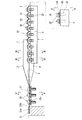
以下、添付図面の図1〜図8に基づいてこの発明の実施の形態を説明する。図1〜図5は、この発明の搬送・矯正装置の第1形態である。この第1形態の搬送・矯正装置10は、Aガイド1とBガイド2とから成る。
Embodiments of the present invention will be described below with reference to FIGS. 1 to 5 show a first embodiment of the conveying / correcting apparatus of the present invention. The conveyance /
例示の装置のAガイド1は、始端から終端までの全域で横に倒れる方向(図2の搬送方向視図において垂直な線に対して右又は左に傾く方向)に傾斜した第1レール3及びこの第1レール3と平行配置の第2レール4と、第1レール3に沿って設けるねじの頭受け5とで構成されている。
The
このAガイド1の始端側は、各々が同一方向に傾いた平行配置の第1レール3と第2レール4によって構成されており(図2参照)、第1、第2レール3,4間に軸部通路6を有している。
The starting end side of the
第1、第2レール3,4は、始端側を傾きのない状態にし、搬送方向前方に行くに従って横に倒れる方向に次第に大きく傾くものであってもよい。所定の傾きが与えられた部分では、図3に示すように、第1レール3がねじの軸部32と第1座金33を下から支えるように構成されている。また、第2レール4は途中からなくなり、その代替として搬送路の終端側では頭受け5が第1レール3に沿って設置されている。
The first and
Bガイド2は、始端側がAガイド1の傾き方向と同方向に傾き、その傾きが終端側に行くに従って徐々に小さくなって終端側が水平になる第1支持板7と第2支持板8を、軸部通路9を間に配して対向配置したものになっている。第1支持板7は、始端が第2支持板8よりもAガイド側に延びだしており、第2支持板8に先行してねじの頭部を支持する。
The
このように構成した第1形態の搬送・矯正装置10は、パーツフィーダ(ボールフィーダや直進フィーダ)などから供給される座金組み込みねじ30をAガイド1が受け取り、整列させて搬送方向前方に移動させる。
In the conveyance /
Aガイド1は、図2に示すように、対をなす第1、第2レール3,4間の軸部通路6に座金組み込みねじ30の軸部32を導入し、ねじの首下にある第1座金(図のそれは平座金)33を第1、第2レール3,4(の搬送面)で下から支える。
As shown in FIG. 2, the
下位の第1レール3は、図3に示すように、傾いた搬送面3aで第1座金33を下から支え、同時に、仰向けになった側の側面でねじの軸部32も支える。第1レール3の傾き角が適切に設定されていると、この状況では第2レール4は不要となる。そこで、搬送路の終端側には、第2レールに代えて頭受け5を設けてあり、その頭受け5がねじの頭部31の外周面を斜め下方から支える。
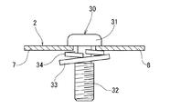
As shown in FIG. 3, the lower
その状況では、第1レール3による第1座金33の支持が片側に偏った状態でなされる。そのために、第1レール3に支えられたねじの軸部32に対して第1座金33が傾き、そのために第2座金34も同様に傾いて、ねじの頭部31と第2座金34との間に隙間gが形成される。その隙間gにBガイド2の支持板が入り込んで座金組み込みねじ30がBガイド2に移される。
In that situation, the
Bガイド2は、そのBガイドを構成する第1、第2支持板7,8の始端側がAガイドのレールと同方向に傾いており、また、第1支持板7の始端が第2支持板8の始端よりもAガイド側に延びだしており、そのために、前記隙間gを生じる側に配置された第1支持板7が第2支持板8に先行して隙間gに入り込み、ねじの頭部31を支持する(図3参照)。
In the
この状況でAガイドの第1レール3が搬送方向前方に向って徐々に第1支持板7から離反する。具体的には、Bガイド2を構成する第1支持板7の始端から第2支持板8の始端までの間において、Aガイドの第1レール3から第1支持板7までのレール高さ方向の距離Lがねじの搬送方向前方で大きくなるように第1レール3の搬送面3aを終点側で前下がりに傾斜させている。
In this situation, the
これによる距離Lの増加で第1、第2座金33,34の位置が下がって(ねじの位置は頭部31が第1支持板7に支持されているので下がらない)第1支持板7の設置側とは反対側でもねじの頭部31と第2座金34との間に隙間gが形成され、その隙間gにBガイド2の第2支持板8が入り込む(図4参照)。このようにしてねじの頭部31がBガイド2の第1、第2支持板7,8に支持され、第1、第2支持板7,8の水平になった終端側でねじの吊り下げ姿勢が垂直に矯正される(図5参照)。
As the distance L increases, the positions of the first and
このために、検査装置などの搬送部22に対する座金組み込みねじ30の供給を、この発明の搬送・矯正装置10を経由させることでねじの頭部を支持して検査などの信頼性を高めることができる。
For this reason, the supply of the washer built-in
なお、距離Lを増加させる目的は、第1レール3の搬送面を前下がり傾斜させることに代えて、Bガイドの第1支持板7の搬送面高さを前上がりに傾斜させることでも達成することができる。
The purpose of increasing the distance L can also be achieved by inclining the height of the conveyance surface of the
また、ねじの搬送は、パーツフィーダなどの供給装置による搬送力を利用して行うことができるので、Aガイド1とBガイド2は、搬送力を発生させる機能の無いものでよいが、既知の直進フィーダと同様の自己搬送機能を付与してもかまわない。
Further, since the screw can be transported by using a transport force by a supply device such as a parts feeder, the
さらに、第1形態の搬送・矯正装置10は、Aガイド1を第1レールのみで構成することができる。この場合、第1レールは全域を傾斜させる。
Furthermore, the conveyance /
図6、図7は、第2形態の搬送・矯正装置10を示している。この第2形態の搬送・矯正装置10は、平行配置の傾きのない第1、第2レール3,4で構成されたAガイド11と、このAガイド11に支持された座金組み込みねじ30をAガイド11の搬送面から浮き上がらせる押し上げ具13と、水平配置の第1、第2支持板7,8を、軸部通路9を間に形成して対向配置したBガイド12とで構成されている。第1、第2支持板7,8は、図7に示すように、軸部通路9の始端側をテーパ状にすると軸部通路9に対するねじの軸部の導入がスムーズになされて好ましい。
6 and 7 show the second embodiment of the conveyance /
Aガイド11は、レール間の軸部通路6に座金組み込みねじ30の軸部32を導入し、ねじの首下にある第1座金33を第1、第2レールで下から支えるように構成されている。第1、第2レール3,4は、その2者がレールの全長にわたって存在する。このAガイド11は、既知のパーツフィーダの搬送路の出口側部分をアレンジして利用することができる(この場合、Aガイド11はパーツフィーダと一体のものになる)。
The
Bガイド12は、搬送面の位置をAガイド11よりも所定量高くしており、これにより、Aガイド11とBガイド12との間に段差hが生じる。
In the
押し上げ具13は、Aガイド11上の座金組み込みねじ30を誘導する斜面のガイド面13aを有しており、そのガイド面13aと搬送中の座金組み込みねじ30の相対移動によりねじの軸部先端がガイド面13aに突き上げられて座金組み込みねじ30のねじ部が所定量持ち上がる。
The push-up
このとき、第1、第2座金33,34は、第1,第2レール3,4による支持点に残り、このために、座金組み込みねじ30の頭部31と第2座金34との間に隙間gが形成される。その隙間gに第1、第2支持板7,8がねじとの相対移動により入り込んで座金組み込みねじ30がBガイド12上に移行する。
At this time, the first and
この第2形態の搬送・矯正装置10も、Bガイド12がねじの頭部31と第2座金34との間に入り込んでねじの頭部31を支える。従って、ねじの吊り下げ姿勢が垂直になり、ねじの傾きに起因した不具合(検査装置の検査精度低下や搬送装置の搬送安定性の低下)がなくなる。なお、第2形態の搬送・矯正装置10は、第1形態よりも構造の単純化が図れるが、移動しているねじの先端を斜面のガイド面13aで誘導してねじを持ち上げるので、搬送の安定性やA,Bガイド間での移行の安定性がガイド面の高さなどに左右される可能性がある。
Also in the second embodiment of the conveyance /
図8に、この発明の搬送・矯正装置10を採用した座金組み込みねじの良否検査装置20の実施の形態を示す。
FIG. 8 shows an embodiment of a
図8の14は市販のパーツフィーダ(図のそれはボールフィーダ)、15も市販のパーツフィーダ(図のそれは直進フィーダ)であり、両者間にこの発明の搬送・矯正装置10が設置されてねじ供給装置16が構成されている。
8 in FIG. 8 is a commercially available parts feeder (ball feeder in the figure), and 15 is a commercially available parts feeder (in the figure is a linear feeder), and the conveying / correcting
パーツフィーダ14は、ボールに収納された座金組み込みねじ30を整列させながら供給する。また、パーツフィーダ15は、平行配置の左右のレール間にねじの軸部を導入し、左右のレールでねじを吊り下げ、レールに振動を加えて搬送力を発生させる。
The
パーツフィーダ14によるねじの支持は、座金を下から支える。この状態で座金組み込みねじ30が既述のAガイドに移され、このAガイドによる搬送途中に座金組み込みねじ30の頭部と首下の座金との間に隙間が作られ、その隙間にBガイドの第1、第2支持板が入り込み、Bガイドによるねじの頭部の支持がなされる。
The screw support by the
その状況を維持して座金組み込みねじ30を良否検査装置の検査部搬送装置21に送り込む。図示の検査部搬送装置21は、垂直軸を支点にして回転する水平配置の搬送テーブル22aを備えており、この搬送テーブル22aの外周部22bはねじの頭部と首下の座金との間に入り込める厚さの板材で形成されている。
The washer built-in
その外周部22bの周縁に座金組み込みねじ30の首下部を受け入れる切欠き溝22cを定ピッチで設けて検査部搬送装置21の搬送部22を構成しており、搬送・矯正装置10によって吊り下げ姿勢が矯正された座金組み込みねじ30が、パーツフィーダ15経由で検査部搬送装置21の搬送部22に移され、座金組み込みねじ30の検査部搬送装置21による搬送がねじの頭部31を支持してなされる。図1、図6に搬送部22によるねじの支持状態も併せて示す。
A
図示のパーツフィーダ15を省いて、搬送・矯正装置10のBガイドから搬送部22に座金組み込みねじ30を供給することが可能である。
The washer built-in
なお、図8の23〜27は、搬送路の途中に設けられた第1〜第5検査部である。このうち、第1検査部23は、ねじの首下長さの検査と頭部高さの検査を行う。また、第2検査部24は、CCDカメラを用いてねじの先端形状、ねじ山ピッチ、ねじ外径、座金の装着漏れなどを検査し、第3検査部25は、CCDカメラを用いてねじの頭部外径、頭部の傷の有無、操作穴の良否を検査する。さらに、第4検査部26はねじの搬送漏れの有無を検査し、第5検査部27は、表面のメッキの有無を検査する。これらの検査部で不良と判定された座金組み込みねじは不良品排出部28から取り出され、良品が良品搬出部29に送られる。この検査部の構成は特徴のあるものではなく、任意に変更することができる。
In addition, 23-27 of FIG. 8 is the 1st-5th test | inspection part provided in the middle of the conveyance path. Among these, the 1st test |
検査部搬送装置21は、装置の小型化などの面で最善と考えられる形態のものを示したが、この形態に限定されるものではない。例えば、直進フィーダや2条のエンドレスワイヤを平行配置にしてローラで駆動し、その2条のワイヤでねじを吊り下げるといったものなども考えられる。
The inspection
1,11 Aガイド
2,12 Bガイド
3 第1レール
3a 搬送面
4 第2レール
5 頭受け
6 軸部通路
7 第1支持板
8 第2支持板
9 軸部通路
10 搬送・矯正装置
13 押し上げ具
13a ガイド面
14,15 パーツフィーダ
16 ねじ供給装置
20 良否検査装置
21 検査部搬送装置
22 搬送部
22a 搬送テーブル
22b 外周部
22c 切欠き溝
23〜27 第1〜第5検査部
28 不良品排出部
29 良品搬出部
30 座金組み込みねじ
31 頭部
32 軸部
33 第1座金
34 第2座金
L 第1レールから第1支持板までのレール高さ方向の距離
h 段差
1, 11 A
Claims (6)
横に倒れる方向に傾斜させた第1レール(3)とその第1レール(3)に沿って設けるねじの頭受け(5)とを備えたAガイド(1)と、始端側がAガイドのレールと同方向に傾き、その傾きが徐々に小さくなって終端側が水平になる第1、第2支持板(7,8)を、軸部通路(9)を間に配して対向配置したBガイド(2)を有し、
前記Aガイド(1)は、座金組み込みねじ(30)の軸部(32)を前記第1レール(3)の仰向けになった側の側面で、ねじの首下にある第1座金(33)を前記第1レール(3)の搬送面(3a)で、ねじの頭部(31)の外周を前記頭受け(5)でそれぞれ下から支えるように構成され、
前記座金組み込みねじ(30)が前記Aガイド(1)に支持された状態下で前記頭部(31)とねじの首下の座金(34)との間に隙間(g)が形成され、
その隙間(g)に前記第1支持板(7)が先行して入り込み、遅れて対向位置の隙間に第2支持板(8)が入り込んで前記Bガイド(2)がねじの頭部(31)を支えるように構成された座金組み込みねじの搬送・矯正装置。 A conveying / correcting device that suspends and conveys a washer built-in screw (30) and corrects the hanging posture of the screw during the conveyance,
A guide (1) having a first rail (3) inclined in a direction to fall sideways and a screw head receiver (5) provided along the first rail (3), and a rail whose start end is an A guide The first and second support plates (7, 8), which are inclined in the same direction as the inclination and gradually become smaller and the end side is horizontal, are arranged opposite to each other with the shaft passage (9) interposed therebetween. (2)
The A guide (1) is a first washer (33) under the neck of the screw on the side surface of the shaft (32) of the washer built-in screw (30) on the side facing the back of the first rail (3). Is supported by the conveying surface (3a) of the first rail (3) and the outer periphery of the screw head (31) from below by the head support (5),
A gap (g) is formed between the head (31) and a washer (34) under the neck of the screw under the condition that the washer built-in screw (30) is supported by the A guide (1).
The first support plate (7) enters the gap (g) in advance, the second support plate (8) enters the gap at the opposite position with a delay, and the B guide (2) moves to the screw head (31). ) Conveyor / straightening device for screw with built-in washer configured to support
平行配置の第1、第2レール(3,4)で構成されたAガイド(11)と、このAガイド(11)に支持された座金組み込みねじ(30)をAガイド(11)から浮き上がらせる押し上げ具(13)と、水平配置の第1、第2支持板(7,8)を、軸部通路(9)を間に形成して対向配置したBガイド(12)とを有し、
前記Aガイド(11)は、レール間の軸部通路(6)に座金組み込みねじ(30)の軸部(32)を導入し、ねじの首下にある第1座金(33)を前記第1、第2レール(3,4)で下から支えるように構成され、
前記押し上げ具(13)は、前記Aガイド(11)に支持されて搬送される座金組み込みねじ(30)を、そのねじの軸部(32)の先端が接触する斜面のガイド面(13a)で誘導して所定量持ち上げるように構成され、この持ち上げで前記座金組み込みねじ(30)の頭部(31)とねじの首下の座金(34)との間に隙間(g)が形成され、その隙間(g)に前記第1、第2支持板(7,8)が入り込むようにBガイド(12)がAガイド(11)に対して所定の段差(h)を生じて配置され、このBガイド(12)がねじの頭部(31)を支えるように構成された座金組み込みねじの搬送・矯正装置。 A conveying / correcting device that suspends and conveys a washer built-in screw (30) and corrects the hanging posture of the screw during the conveyance,
The A guide (11) composed of the first and second rails (3, 4) arranged in parallel and the washer built-in screw (30) supported by the A guide (11) are lifted from the A guide (11). A push-up tool (13), and a horizontally arranged first and second support plates (7, 8) having a B guide (12) arranged opposite to each other with a shaft passage (9) interposed therebetween,
The A guide (11) introduces the shaft portion (32) of the washer-incorporating screw (30) into the shaft passage (6) between the rails, and the first washer (33) under the neck of the screw is inserted into the first guide (11). The second rail (3, 4) is configured to be supported from below,
The push-up tool (13) moves the washer-incorporating screw (30) supported and conveyed by the A guide (11) on the inclined guide surface (13a) where the tip of the shaft (32) of the screw contacts. It is configured to be guided and lifted by a predetermined amount, and by this lifting, a gap (g) is formed between the head (31) of the washer built-in screw (30) and the washer (34) under the neck of the screw. The B guide (12) is arranged with a predetermined step (h) with respect to the A guide (11) so that the first and second support plates (7, 8) enter the gap (g). Conveyor / straightening device for screw with built-in washer configured such that guide (12) supports screw head (31).
そのねじ供給装置(16)に請求項1〜4のいずれかに記載の座金組み込みねじの搬送・矯正装置(10)が含まれており、
その搬送・矯正装置(10)によって吊り下げ姿勢が矯正された座金組み込みねじ(30)が、前記搬送部(22)に対して前記Bガイド又はBガイドと検査部搬送装置(21)との間に介在させたフィーダ(15)から移され、座金組み込みねじ(30)の検査部搬送装置(21)による搬送がねじの頭部(31)を支持してなされるようにした座金組み込みねじの検査装置。 A washer built-in screw (30) is hung and conveyed by an inspection unit conveying device (21), and passes through an inspection station in the middle of conveyance to perform a pass / fail inspection. The inspection unit conveying device The transport part (22) of (21) can be inserted into the gap between the head (31) of the washer built-in screw and the washer (34) under the neck, and this inspection part transport device (21) A screw supply device (16) for supplying a washer built-in screw (30)
The screw feeder (16) includes the washer built-in screw conveyance / correction device (10) according to any one of claims 1 to 4,
The washer built-in screw (30) whose hanging posture is corrected by the conveying / correcting device (10) is between the B guide or the B guide and the inspection unit conveying device (21) with respect to the conveying unit (22). Inspection of a washer-incorporated screw transferred from the feeder (15) interposed in the machine and supported by the screw head (31) by the inspection unit conveying device (21) of the washer-incorporated screw (30). apparatus.
Priority Applications (1)
| Application Number | Priority Date | Filing Date | Title |
|---|---|---|---|
| JP2008199246A JP4911535B2 (en) | 2008-08-01 | 2008-08-01 | Conveyor straightening device and inspection device for washer built-in screw |
Applications Claiming Priority (1)
| Application Number | Priority Date | Filing Date | Title |
|---|---|---|---|
| JP2008199246A JP4911535B2 (en) | 2008-08-01 | 2008-08-01 | Conveyor straightening device and inspection device for washer built-in screw |
Publications (2)
| Publication Number | Publication Date |
|---|---|
| JP2010037013A true JP2010037013A (en) | 2010-02-18 |
| JP4911535B2 JP4911535B2 (en) | 2012-04-04 |
Family
ID=42009959
Family Applications (1)
| Application Number | Title | Priority Date | Filing Date |
|---|---|---|---|
| JP2008199246A Active JP4911535B2 (en) | 2008-08-01 | 2008-08-01 | Conveyor straightening device and inspection device for washer built-in screw |
Country Status (1)
| Country | Link |
|---|---|
| JP (1) | JP4911535B2 (en) |
Cited By (4)
| Publication number | Priority date | Publication date | Assignee | Title |
|---|---|---|---|---|
| JP2011246264A (en) * | 2010-05-28 | 2011-12-08 | Nitto Seiko Co Ltd | Part supply device |
| JP2013159412A (en) * | 2012-02-01 | 2013-08-19 | Mitsubishi Electric Corp | Part supply device |
| JP2013199361A (en) * | 2012-03-26 | 2013-10-03 | Hirata Neji Kk | Transporting device of screw |
| CN105217284A (en) * | 2015-09-08 | 2016-01-06 | 惠州智科实业有限公司 | A kind of T-shaped nail vibration feeding commutating structure |
Families Citing this family (1)
| Publication number | Priority date | Publication date | Assignee | Title |
|---|---|---|---|---|
| CN105564910B (en) * | 2016-02-03 | 2018-01-30 | 林尧宇 | A kind of vibrating disk component of pearl nailer |
Citations (4)
| Publication number | Priority date | Publication date | Assignee | Title |
|---|---|---|---|---|
| JPH02231306A (en) * | 1989-03-02 | 1990-09-13 | Shinko Electric Co Ltd | Bolt/washer combining device |
| JPH06218639A (en) * | 1993-01-21 | 1994-08-09 | Toyoda Gosei Co Ltd | Part feeding device |
| JPH09216715A (en) * | 1996-02-13 | 1997-08-19 | Mitsubishi Electric Corp | Screw parts feeder |
| JP2007055763A (en) * | 2005-08-25 | 2007-03-08 | Yutaka:Kk | Attitude correction device for shaft body with head and inspection device for shaft body with head |
-
2008
- 2008-08-01 JP JP2008199246A patent/JP4911535B2/en active Active
Patent Citations (4)
| Publication number | Priority date | Publication date | Assignee | Title |
|---|---|---|---|---|
| JPH02231306A (en) * | 1989-03-02 | 1990-09-13 | Shinko Electric Co Ltd | Bolt/washer combining device |
| JPH06218639A (en) * | 1993-01-21 | 1994-08-09 | Toyoda Gosei Co Ltd | Part feeding device |
| JPH09216715A (en) * | 1996-02-13 | 1997-08-19 | Mitsubishi Electric Corp | Screw parts feeder |
| JP2007055763A (en) * | 2005-08-25 | 2007-03-08 | Yutaka:Kk | Attitude correction device for shaft body with head and inspection device for shaft body with head |
Cited By (4)
| Publication number | Priority date | Publication date | Assignee | Title |
|---|---|---|---|---|
| JP2011246264A (en) * | 2010-05-28 | 2011-12-08 | Nitto Seiko Co Ltd | Part supply device |
| JP2013159412A (en) * | 2012-02-01 | 2013-08-19 | Mitsubishi Electric Corp | Part supply device |
| JP2013199361A (en) * | 2012-03-26 | 2013-10-03 | Hirata Neji Kk | Transporting device of screw |
| CN105217284A (en) * | 2015-09-08 | 2016-01-06 | 惠州智科实业有限公司 | A kind of T-shaped nail vibration feeding commutating structure |
Also Published As
| Publication number | Publication date |
|---|---|
| JP4911535B2 (en) | 2012-04-04 |
Similar Documents
| Publication | Publication Date | Title |
|---|---|---|
| JP4911535B2 (en) | Conveyor straightening device and inspection device for washer built-in screw | |
| JP2007121022A (en) | Nut inspection device | |
| KR101385790B1 (en) | Method for transferring optical film and apparatus employing the method | |
| WO2009118952A1 (en) | Glass substrate inspecting apparatus and glass substrate inspecting method | |
| JP2009098052A (en) | Substrate gripping mechanism for substrate transferring device | |
| JP2011189501A (en) | Bar material loading device for machining in machine tool | |
| JP2014034103A (en) | Component transfer head, component suction nozzle, and component mounting apparatus | |
| KR102605917B1 (en) | Scribing apparatus | |
| KR20160129131A (en) | A conveyer system of assist | |
| CN1287912C (en) | External testing apparatus for workpiece and external testing method | |
| JP2007153568A (en) | Carrying device of shaft body with head part | |
| JP2006019469A (en) | Method and apparatus of packaging electronic part | |
| KR20130096120A (en) | Aligned screw feeding device | |
| JP6348037B2 (en) | Component mounter | |
| KR101504970B1 (en) | Transport Apparatus | |
| KR101912037B1 (en) | An Automatic Apparatus For Forming Spindle Screws | |
| JP2007055763A (en) | Attitude correction device for shaft body with head and inspection device for shaft body with head | |
| JP4333967B1 (en) | Pallet for substrate transfer | |
| JP2021150560A (en) | Mounting board manufacturing system and mounting board manufacturing method | |
| JP5237585B2 (en) | Structure of auxiliary roller conveyor for transit | |
| JP2009057159A (en) | Shaft body conveying device and shaft body inspection device using the same | |
| JP2000096296A (en) | Continuous plating device | |
| JP4847097B2 (en) | Transport device | |
| CN109573616B (en) | Detection system | |
| CN209211003U (en) | The upper spider of high-speed stretch yarn machine |
Legal Events
| Date | Code | Title | Description |
|---|---|---|---|
| A621 | Written request for application examination |
Free format text: JAPANESE INTERMEDIATE CODE: A621 Effective date: 20110707 |
|
| A871 | Explanation of circumstances concerning accelerated examination |
Free format text: JAPANESE INTERMEDIATE CODE: A871 Effective date: 20110712 |
|
| A975 | Report on accelerated examination |
Free format text: JAPANESE INTERMEDIATE CODE: A971005 Effective date: 20110803 |
|
| A977 | Report on retrieval |
Free format text: JAPANESE INTERMEDIATE CODE: A971007 Effective date: 20111128 |
|
| TRDD | Decision of grant or rejection written | ||
| A01 | Written decision to grant a patent or to grant a registration (utility model) |
Free format text: JAPANESE INTERMEDIATE CODE: A01 Effective date: 20111213 |
|
| A01 | Written decision to grant a patent or to grant a registration (utility model) |
Free format text: JAPANESE INTERMEDIATE CODE: A01 |
|
| A61 | First payment of annual fees (during grant procedure) |
Free format text: JAPANESE INTERMEDIATE CODE: A61 Effective date: 20120111 |
|
| R150 | Certificate of patent or registration of utility model |
Ref document number: 4911535 Country of ref document: JP Free format text: JAPANESE INTERMEDIATE CODE: R150 Free format text: JAPANESE INTERMEDIATE CODE: R150 |
|
| FPAY | Renewal fee payment (event date is renewal date of database) |
Free format text: PAYMENT UNTIL: 20150127 Year of fee payment: 3 |
|
| R250 | Receipt of annual fees |
Free format text: JAPANESE INTERMEDIATE CODE: R250 |
|
| R250 | Receipt of annual fees |
Free format text: JAPANESE INTERMEDIATE CODE: R250 |
|
| R250 | Receipt of annual fees |
Free format text: JAPANESE INTERMEDIATE CODE: R250 |
|
| R250 | Receipt of annual fees |
Free format text: JAPANESE INTERMEDIATE CODE: R250 |
|
| R250 | Receipt of annual fees |
Free format text: JAPANESE INTERMEDIATE CODE: R250 |
|
| R250 | Receipt of annual fees |
Free format text: JAPANESE INTERMEDIATE CODE: R250 |
|
| R250 | Receipt of annual fees |
Free format text: JAPANESE INTERMEDIATE CODE: R250 |
|
| R250 | Receipt of annual fees |
Free format text: JAPANESE INTERMEDIATE CODE: R250 |
|
| R250 | Receipt of annual fees |
Free format text: JAPANESE INTERMEDIATE CODE: R250 |
|
| R250 | Receipt of annual fees |
Free format text: JAPANESE INTERMEDIATE CODE: R250 |