JP2010036490A - Laminate method of bubble sheet and lamination film supply device used for this method - Google Patents
Laminate method of bubble sheet and lamination film supply device used for this method Download PDFInfo
- Publication number
- JP2010036490A JP2010036490A JP2008203059A JP2008203059A JP2010036490A JP 2010036490 A JP2010036490 A JP 2010036490A JP 2008203059 A JP2008203059 A JP 2008203059A JP 2008203059 A JP2008203059 A JP 2008203059A JP 2010036490 A JP2010036490 A JP 2010036490A
- Authority
- JP
- Japan
- Prior art keywords
- film
- bubble sheet
- laminating
- laminate
- brake
- Prior art date
- Legal status (The legal status is an assumption and is not a legal conclusion. Google has not performed a legal analysis and makes no representation as to the accuracy of the status listed.)
- Granted
Links
Images


Landscapes
- Laminated Bodies (AREA)
- Lining Or Joining Of Plastics Or The Like (AREA)
Abstract
Description
本発明は、気泡シートのラミネート方法及びその方法の実施に使用されるラミネートフィルム供給装置に関する。 The present invention relates to a method for laminating a bubble sheet and a laminate film supply apparatus used for carrying out the method.
2層または3層の気泡シートの平らな面に機能性フィルムをラミネートすることは従来から行なわれている。特許文献1は、その一例を開示するもので、1枚の機能性フィルム、例えば、彩色や絵柄を与えるためフィルム、ガスバリヤ性を付与するためのフィルム、あるいは熱線反射性能を与えるためのフィルムなどのいずれかを気泡シートにラミネートする技術をその実施の態様として示している。
しかし近年は多様化するニーズに応えるために、複数種類の機能性フィルムを一つの気泡シートに貼着しなければならないことも少なくない。例えば、防錆機能を備えたラミネートシールと脱酸素機能を備えたフィルムを共通の気泡シートにラミネートするなど種々の試みがなされている。 However, in recent years, in order to meet diversifying needs, it is often necessary to attach a plurality of types of functional films to a single bubble sheet. For example, various attempts have been made such as laminating a laminate seal having a rust prevention function and a film having a deoxidation function on a common cell sheet.
また、気泡シートの製品巾は標準で1200mmあるが、各種機能性フィルムの中にはこの巾に満たないものも多く、その場合は1種類のフィルムを複数並べてラミネートしなければならない。 In addition, the product width of the bubble sheet is 1200 mm as a standard, but there are many types of functional films that do not satisfy this width, and in that case, a plurality of one type of films must be laminated side by side.
さらに防錆性フィルムや導電性フィルムの場合、樹脂に薬剤や無機フィラーを練りこんだり、表面に蒸着層を設けたりしているので、この層が内側に来るようにヒートシール等で製袋すると、異物の存在により強固にシールすることができない。この様な不具合を改善するには、巾狭のフィルムを間隔をあけてラミネートして、非ラミネート部によって強固にシールした袋を作ることが考えられる。 Furthermore, in the case of a rust-proof film or conductive film, since a chemical or inorganic filler is kneaded into the resin, or a vapor deposition layer is provided on the surface, if you make a bag with heat seal etc. so that this layer comes inside It cannot be sealed firmly due to the presence of foreign matter. In order to improve such a problem, it is conceivable to make a bag tightly sealed by a non-laminate part by laminating narrow films at intervals.
以上のような理由から、気泡シートの平坦な面に巾方向に複数に分割されたフィルムを、隙間をあけて或いは密接させて並べてラミネートすることが望まれている。 For the reasons described above, it is desired to laminate a film, which is divided in the width direction, on the flat surface of the air bubble sheet, with a gap or close contact therebetween.
そこで、本発明者らは、巾方向に分割されていない1枚のラミネートフィルムを気泡シートに貼着するための従来の装置に複数のフィルムを掛けてラミネートを試みたが、良好な結果を得ることができなかった。 Therefore, the present inventors tried laminating by laminating a plurality of films on a conventional apparatus for adhering a single laminated film that is not divided in the width direction to a bubble sheet, and obtained good results. I couldn't.
すなわち、従来のラミネートフィルム供給装置では、セットした複数のフィルムの張力を一括して調整することしかできない。しかるに、個々のフィルムの繰り出し時に該フィルムのたるみを取る為に必要なテンションは微妙に異なる。そのため、一つのフィルムに照準を当ててブレーキの重さを調整すると、他のフィルムにとってブレーキが重すぎたり軽すぎたりする結果を招き、他のフィルムが蛇行したりシワになって良品を得ることが出来ないという問題があった。 That is, with the conventional laminated film supply apparatus, it is only possible to collectively adjust the tension of a plurality of set films. However, the tension required to take up the slack of the individual films is slightly different. Therefore, aiming at one film and adjusting the weight of the brake will result in the brakes being too heavy or too light for other films, and other films will meander or wrinkle to get a good product. There was a problem that was not possible.
本発明は、このような不具合を解消することを目的とするものである。 The present invention aims to eliminate such problems.
本発明は、以上説明したような問題を解決するために、個々のラミネートフィルムに作用させる張力を各別に調整するようにしたものである。 In the present invention, in order to solve the problems as described above, the tension applied to each laminate film is adjusted separately.
すなわち、本発明に係る気泡シートのラミネート方法は、キャップフィルム、バックフィルムからなる2層の気泡シートあるいはキャップフィルム、バックフィルム、ライナーフィルムからなる3層の気泡シートにおける平坦なフィルムの一方または両方に、巾方向に2つ以上に分割されたラミネートフィルムをラミネートする方法であって、その2つ以上のラミネートフィルムの原反掛けに、個々にラミネートフィルムの張力を調整するブレーキ機構を設けておき、張力を個別に調節されて前記原反掛けから順次繰り出される各ラミネートフィルムを前記気泡シートにラミネートすることを特徴とするものである。 That is, the method for laminating a bubble sheet according to the present invention is applied to one or both of a two-layer bubble sheet composed of a cap film and a back film or a flat film in a three-layer bubble sheet composed of a cap film, a back film and a liner film. , A method of laminating a laminate film divided into two or more in the width direction, and a brake mechanism for individually adjusting the tension of the laminate film is provided on the raw fabric hook of the two or more laminate films, Each laminate film, which is adjusted in tension individually and is sequentially drawn out from the original fabric hook, is laminated on the bubble sheet.
代表的な態様としては、前記2つ以上に分割されたラミネートフィルムが、巾方向に所定の間隔をあけて配される場合を挙げることができるが、2つ以上に分割されたラミネートフィルムを密接させて配してもよい。ここで、2つ以上に分割されたラミネートフィルムは、相互に異なった種類のものであってもよいし、同じ種類のものであってもよい。 As a typical embodiment, there can be mentioned a case where the laminate film divided into two or more is arranged with a predetermined interval in the width direction. It may be arranged. Here, the laminate film divided into two or more may be of different types or of the same type.
ラミネートフィルムとしては、防錆機能を有したもの、脱酸素機能を有したもの、導電機能を有したものなど、種々の機能性フィルムを使用することができる。 As the laminate film, various functional films such as those having a rust prevention function, those having a deoxidation function, and those having a conductive function can be used.
このような気泡シートのラミネート方法に使用されるラミネートフィルム供給装置としては、それぞれにラミネートフィルムが繰出し可能に巻装され個別に回転可能な複数の原反掛けと、これら各原反掛けのフィルム繰出時における回転抵抗を個別に調節するためのブレーキ機構とを具備してなるものを挙げることができる。 As a laminate film supply device used in such a method for laminating a bubble sheet, a laminate film can be unwound and wound on each of a plurality of original fabric hooks, and the film feed of each of these raw fabric hooks And a brake mechanism for individually adjusting the rotational resistance at the time.
前記ブレーキ機構の好適な態様としては、ブレーキ支持杆と、このブレーキ支持杆に基端部を支持させ先端部を対応する原反掛けのカラー部にそれぞれ摺接させた複数の板ばね状をなすブレーキと、これら各ブレーキの前記カラー部への圧接力をそれぞれ調節するブレーキ圧縮手段とを具備してなるものが考えられる。 As a preferable aspect of the brake mechanism, a brake support rod and a plurality of leaf springs having a base end portion supported by the brake support rod and a distal end portion in sliding contact with the corresponding collar portion of the original fabric are formed. It is conceivable to include a brake and brake compression means for adjusting the pressure contact force of each brake to the collar portion.
請求項1に係る発明によれば、巾方向に分割された2つ以上のラミネートフィルムに対して、それぞれ最適な張力を付与した状態で気泡シートに対するラミネート作業を行なうことができる。そのため、全てのラミネートフィルムが適切に繰り出され蛇行や緩みを生じることなくラミネートされるという効果を奏する。 According to the invention which concerns on Claim 1, the lamination operation | work with respect to a bubble sheet can be performed in the state which provided the optimal tension | tensile_strength with respect to the 2 or more laminated film divided | segmented in the width direction, respectively. Therefore, there is an effect that all the laminated films are properly drawn out and laminated without causing meandering or loosening.
請求項2に係る発明によれば、各ラミネートフィルムの原反掛け間にも隙間を形成することが可能になるため、ブレーキ機構の構成部品などを効率的に配置することができ、設計の自由度を向上させることができる。 According to the second aspect of the present invention, since it is possible to form a gap between the raw films of each laminate film, the components of the brake mechanism can be arranged efficiently, and the design freedom The degree can be improved.
請求項3に係る発明によれば、各ラミネートフィルムの原反掛けにそれぞれ最適化されたブレーキ力を各別に作用させることができる。そのため、前記発明に係るラミネート方法を容易に実施することができるラミネートフィルム供給装置を提供することができる。
According to the invention which concerns on
請求項4に係る発明によれば、前記ラミネートフィルム供給装置のブレーキ機構を簡素な部品により構成することができる。そのため、前記ラミネートフィルム供給装置の実施化を特に容易にすることが可能となる。 According to the invention which concerns on Claim 4, the brake mechanism of the said laminate film supply apparatus can be comprised by simple components. Therefore, implementation of the laminate film supply device can be made particularly easy.
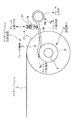
図1から図5に示す実施形態は、キャップフィルムSCとバックフィルムSBからなる2層の気泡シートSを対象としたものである。そして、その気泡シートSの平坦なフィルムである前記バックフィルムSBに、巾方向に2つ以上に分割されたラミネートフィルムLをラミネートする方法であって、その2つ以上のラミネートフィルムLの原反掛け2に、個々にラミネートフィルムLの張力を調整するブレーキ機構3を設けておき、張力を個別に調節されて前記原反掛け2から順次繰り出される各ラミネートフィルムLを前記気泡シートSにラミネートするようにした気泡シートSのラミネート方法を示している。
The embodiment shown in FIGS. 1 to 5 is directed to a two-layered bubble sheet S composed of a cap film SC and a back film SB. A method of laminating a laminate film L divided into two or more in the width direction on the back film SB, which is a flat film of the bubble sheet S, is a method of laminating the two or more laminate films L.
このラミネート方法は、例えば、従来から知られている2層の気泡シートSの製造ラインの途中に、本発明に係るラミネートフィルム供給装置1を配することによって実施される。 This laminating method is carried out, for example, by arranging the laminate film supply device 1 according to the present invention in the middle of a production line for a two-layered bubble sheet S that has been conventionally known.
具体的に説明すれば、2層構造をなす気泡シートSの製造ラインは、図1に模式的に示すように、キャップフィルム用ダイスD1から熱可塑化状態にある膜状のキャップフィルム用素材SCaが連続回転している真空成形ロールRに逐次供給され、真空成形ロールRの吸引キャビティR11に対応した形状の気泡用突起SC1を有するキャップフィルムSCが連続的に形成されるようになっている。また、バックフィルム用ダイスD2から熱可塑化状態にある膜状のバックフィルム用素材SBaが回転している真空成形ロールRに逐次供給され、加圧ロールRAにより前記バックフィルム用素材SBaを前記キャップフィルムSCの裏面側に押し付けて貼り合せるように構成されている。この工程を通過することによって、キャップフィルムSCとバックフィルムSBとからなり十分に密封された多数の気泡S1を有する2層構造の気泡シートSが形成されるようになっている。その後、その気泡シートSが剥離ロールRBにより真空成形ロールRから剥離され、ピンチロールRCへと移行して完成工程へと搬送されるように構成されている。 Specifically, the production line of the bubble sheet S having a two-layer structure is schematically shown in FIG. 1, and the film-shaped cap film material SCa in a thermoplastic state from the cap film die D1 is shown in FIG. Are sequentially supplied to the continuously rotating vacuum forming roll R, and the cap film SC having the bubble protrusion SC1 having a shape corresponding to the suction cavity R11 of the vacuum forming roll R is continuously formed. Further, a film-like back film material SBa in a thermoplastic state is sequentially supplied from a back film die D2 to a rotating vacuum forming roll R, and the back film material SBa is capped by a pressure roll RA. The film SC is configured to be pressed and bonded to the back side of the film SC. By passing through this step, a two-layered bubble sheet S composed of a cap film SC and a back film SB and having a large number of sufficiently sealed bubbles S1 is formed. Thereafter, the air bubble sheet S is peeled off from the vacuum forming roll R by the peeling roll RB, transferred to the pinch roll RC, and conveyed to the completion process.
このような製造ラインにおける、例えば、真空成形ロールRに関連する位置に、前記ラミネートフィルム供給装置1が配設されている。ラミネートフィルム供給装置1は、それぞれにラミネートフィルムLが繰出し可能に巻装され個別に回転可能な複数の原反掛け2と、これら各原反掛け2のフィルム繰出時における回転抵抗を個別に調節するためのブレーキ機構3とを具備してなるもので、各原反掛け2から繰り出される複数のラミネートフィルムLは、例えば、前記真空成形ロールRと前記加圧ロールRAとの間に漸次供給されるようになっている。
In such a production line, for example, the laminate film supply device 1 is disposed at a position related to the vacuum forming roll R. Laminate film supply apparatus 1 individually adjusts a plurality of
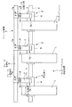
詳述すれば、複数の原反掛け2は、共通の主軸4にそれぞれ独立回転可能に軸装されており、図示しないスペーサ等により相互に一定の間隔をあけて配置されている。各原反掛け2には、それぞれラミネートフィルムLが巻装されており、これら各原反掛け2から繰り出されるラミネートフィルムLが、前記真空成形ロールRと前記加圧ロールRAとの間に漸次供給され、これら真空成形ロールR及び加圧ロールRAの回転に伴って走行するバックフィルムSBの外面に連続的に添着されるようになっている。しかして、この実施形態では、例えば図3、図4、及び図5に示すように、防錆機能を有した複数のラミネートフィルムLを隙間をあけて添着するようにしている。
More specifically, the plurality of
ブレーキ機構3は、各ラミネートフィルムLが原反掛け2から繰り出される際に、前記各原反掛け2に個別に調整されたブレーキ力を付与するためのもので、ブレーキ支持杆55と、このブレーキ支持杆5に基端部7aを支持させ先端部7bを対応する原反掛け2のカラー部6にそれぞれ摺接させた複数の板ばね状をなすブレーキ7と、これら各ブレーキ7の前記カラー部6への圧接力をそれぞれ調節する複数のブレーキ圧縮手段8とを具備してなる。各ブレーキ圧縮手段8は、例えば、図示しない装置フレームなどに固設された台座9と、この台座9に穿設した雌ねじ孔9aに螺合進退可能に装着した調整ボルト10とをそれぞれ具備してなるもので、前記調整ボルト10の先端で前記ブレーキ7の中間部を、該ブレーキ7の先端部7bが前記カラー部6に圧接される方向に押圧し得るようになっている。なお、11は、調整後に前記調整ボルト10が緩むのを防止するためのナットである。
The
このような構成のものであれば、各調整ボルト10を台座9に対して螺合進退させることによって、各ブレーキ7の各カラー部6に対する圧接力を変化させることができ、各ブレーキ7と各カラー部6との摺動摩擦抵抗の大きさを個別に調節することができる。そのため、各原反掛け2から気泡シートSの移動に伴う牽引力により繰り出される各ラミネートフィルムLの張力を個別に調整することが可能となり、それぞれのラミネートフィルムLに最適な状態を維持することができる。したがって、一部のラミネートフィルムLが張力不調により蛇行したりシワになるという不具合の発生を効果的に抑制又は防止することができる。
If it is a thing of such a structure, the pressure contact force with respect to each
なお、本発明は、以上の実施形態に限られないのは勿論である。 Needless to say, the present invention is not limited to the above embodiment.
すなわち、ラミネートの対象となる気泡シートは、2層のものに限られず、キャップフィルム、バックフィルム、及びライナーフィルムからなる3層構造のものであってもよい。この場合、前記バックフィルム若しくは前記ライナーフィルムのいずれか一方、又は、両方にラミネートフィルムを添着すればよい。図6は、ライナーフィルムSL側にラミネートフィルムLを添着する場合の製造ラインを模式的に示すものであり、図1に示すものと同一あるいは相当する部分には、同一の符号を付して説明を省略する。 That is, the air bubble sheet to be laminated is not limited to a two-layer one, but may have a three-layer structure including a cap film, a back film, and a liner film. In this case, a laminate film may be attached to either one or both of the back film and the liner film. FIG. 6 schematically shows a production line when the laminate film L is attached to the liner film SL side, and the same or corresponding parts as those shown in FIG. Is omitted.
キャップフィルム、バックフィルム、ライナーフィルムは、可撓性の良好な薄手のものに限らず、ある程度剛性のある厚手のものであってもよい。 The cap film, the back film, and the liner film are not limited to thin ones having good flexibility, but may be thick ones that are somewhat rigid.
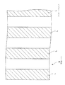
前記実施形態では、防錆機能を有した複数のラミネートフィルムを複数枚間隔をあけてラミネートする場合について説明したが、同種類の複数のラミネートフィルム又は異なった種類の複数のラミネートフィルムを密にラミネートするようにしてもよい。図7は、防錆機能を有したラミネートフィルムLと、脱酸素機能を有したラミネートフィルムL2とを交互に密に配設した例を示している。 In the above embodiment, a case where a plurality of laminate films having a rust prevention function are laminated at intervals is described. However, a plurality of laminate films of the same type or a plurality of laminate films of different types are densely laminated. You may make it do. FIG. 7 shows an example in which laminate films L having a rust prevention function and laminate films L2 having a deoxidation function are alternately and densely arranged.
また、前記実施形態では、一系列のラミネートフィルム供給装置を設けた場合について説明したが、ラミネートフィルムを密に配する場合等には、複数系列のラミネートフィルム供給装置を設けてもよい。 Moreover, although the said embodiment demonstrated the case where the laminated film supply apparatus of 1 series was provided, when laminating a laminate film densely etc., you may provide multiple series of laminated film supply apparatuses.
ブレーキ機構は、図示例のものに限らず、例えば、発電機と可変抵抗器とを組み合わせた回生ブレーキタイプのものであってもよい。 The brake mechanism is not limited to the illustrated example, and may be, for example, a regenerative brake type in which a generator and a variable resistor are combined.
その他、本発明の趣旨を損ねない範囲で種々に変形してよい。 In addition, various modifications may be made without departing from the spirit of the present invention.
1…ラミネートフィルム供給装置
2…原反掛け
3…ブレーキ機構
5…ブレーキ支持杆
7…ブレーキ
7a…ブレーキの基端部
7b…ブレーキの先端部
8…ブレーキ圧縮手段
S…気泡シート
SC…キャップフィルム
SB…バックフィルム
SL…ライナーフィルム
L、L2…ラミネートフィルム
DESCRIPTION OF SYMBOLS 1 ... Laminate
Claims (4)
Priority Applications (1)
| Application Number | Priority Date | Filing Date | Title |
|---|---|---|---|
| JP2008203059A JP5312871B2 (en) | 2008-08-06 | 2008-08-06 | A method for laminating a bubble sheet and a laminating film supply device used in the method. |
Applications Claiming Priority (1)
| Application Number | Priority Date | Filing Date | Title |
|---|---|---|---|
| JP2008203059A JP5312871B2 (en) | 2008-08-06 | 2008-08-06 | A method for laminating a bubble sheet and a laminating film supply device used in the method. |
Publications (2)
| Publication Number | Publication Date |
|---|---|
| JP2010036490A true JP2010036490A (en) | 2010-02-18 |
| JP5312871B2 JP5312871B2 (en) | 2013-10-09 |
Family
ID=42009528
Family Applications (1)
| Application Number | Title | Priority Date | Filing Date |
|---|---|---|---|
| JP2008203059A Expired - Fee Related JP5312871B2 (en) | 2008-08-06 | 2008-08-06 | A method for laminating a bubble sheet and a laminating film supply device used in the method. |
Country Status (1)
| Country | Link |
|---|---|
| JP (1) | JP5312871B2 (en) |
Cited By (1)
| Publication number | Priority date | Publication date | Assignee | Title |
|---|---|---|---|---|
| JP2015123709A (en) * | 2013-12-27 | 2015-07-06 | 宇部エクシモ株式会社 | Manufacturing method of hollow structure plate |
Citations (4)
| Publication number | Priority date | Publication date | Assignee | Title |
|---|---|---|---|---|
| JPH05261817A (en) * | 1992-03-21 | 1993-10-12 | Canon Aptecs Kk | Laminating device and sheet material cutting device |
| JP2007044979A (en) * | 2005-08-09 | 2007-02-22 | Kawakami Sangyo Co Ltd | Method and apparatus for producing plastic bubble sheet with lamination film laminated on back film |
| JP2007283728A (en) * | 2006-04-20 | 2007-11-01 | Reo Techno:Kk | Laminator |
| JP2008132776A (en) * | 2006-10-27 | 2008-06-12 | Fujifilm Corp | Manufacturing apparatus of photosensitive laminate |
-
2008
- 2008-08-06 JP JP2008203059A patent/JP5312871B2/en not_active Expired - Fee Related
Patent Citations (4)
| Publication number | Priority date | Publication date | Assignee | Title |
|---|---|---|---|---|
| JPH05261817A (en) * | 1992-03-21 | 1993-10-12 | Canon Aptecs Kk | Laminating device and sheet material cutting device |
| JP2007044979A (en) * | 2005-08-09 | 2007-02-22 | Kawakami Sangyo Co Ltd | Method and apparatus for producing plastic bubble sheet with lamination film laminated on back film |
| JP2007283728A (en) * | 2006-04-20 | 2007-11-01 | Reo Techno:Kk | Laminator |
| JP2008132776A (en) * | 2006-10-27 | 2008-06-12 | Fujifilm Corp | Manufacturing apparatus of photosensitive laminate |
Cited By (1)
| Publication number | Priority date | Publication date | Assignee | Title |
|---|---|---|---|---|
| JP2015123709A (en) * | 2013-12-27 | 2015-07-06 | 宇部エクシモ株式会社 | Manufacturing method of hollow structure plate |
Also Published As
| Publication number | Publication date |
|---|---|
| JP5312871B2 (en) | 2013-10-09 |
Similar Documents
| Publication | Publication Date | Title |
|---|---|---|
| JP5546281B2 (en) | Label manufacturing apparatus and label printing machine | |
| JP5785259B2 (en) | Head for sticking fiber strip | |
| WO2011078336A1 (en) | Device for laminating reinforcement fiber base material and method for laminating same | |
| JP6496223B2 (en) | Laminated label body manufacturing equipment | |
| JP4135768B2 (en) | Intermittent film forming apparatus and method | |
| JP2010162732A (en) | Double-sided printing apparatus | |
| WO2014064114A1 (en) | Hot stamping machine | |
| JP2019042950A (en) | Manufacturing device of laminated label body | |
| JP6682843B2 (en) | Winding device and label printing device | |
| JP2019042950A5 (en) | ||
| JP5312871B2 (en) | A method for laminating a bubble sheet and a laminating film supply device used in the method. | |
| JP5808156B2 (en) | Multilayer adsorption sheet | |
| JP2006213035A (en) | Laminating apparatus, and label printing machine | |
| CN102555395B (en) | Pneumatic composite double-roll device | |
| CN201634263U (en) | Coating fabric reeling-unreeling constant tension controlling mechanism | |
| JP2008105408A (en) | Intermittent type film shaping apparatus and shaping method | |
| RU2619609C2 (en) | Machines for decoration, in particular for decoration of ceramics, and method of performing belt for decoration of the noted ceramics | |
| WO2018223684A1 (en) | Roll forming device for plastic floor | |
| JPH10305544A (en) | Roll laminating device | |
| JP2013054932A (en) | Roll press device of electrode plate for battery | |
| JP6520443B2 (en) | Outline cutting device | |
| JP6014822B2 (en) | Laminating machine equipped with switching mechanism between release paper winding function and product side film winding function | |
| JP2008126578A (en) | Production line of strip-shaped reinforcing member, and method for production of this member | |
| JP2007092196A (en) | Mold release paper for embossing | |
| CN215287332U (en) | Tension-controllable winding and unwinding device of laminating machine |
Legal Events
| Date | Code | Title | Description |
|---|---|---|---|
| A621 | Written request for application examination |
Free format text: JAPANESE INTERMEDIATE CODE: A621 Effective date: 20110801 |
|
| A977 | Report on retrieval |
Free format text: JAPANESE INTERMEDIATE CODE: A971007 Effective date: 20120907 |
|
| A131 | Notification of reasons for refusal |
Free format text: JAPANESE INTERMEDIATE CODE: A131 Effective date: 20120925 |
|
| A521 | Written amendment |
Free format text: JAPANESE INTERMEDIATE CODE: A523 Effective date: 20121031 |
|
| TRDD | Decision of grant or rejection written | ||
| A01 | Written decision to grant a patent or to grant a registration (utility model) |
Free format text: JAPANESE INTERMEDIATE CODE: A01 Effective date: 20130618 |
|
| A61 | First payment of annual fees (during grant procedure) |
Free format text: JAPANESE INTERMEDIATE CODE: A61 Effective date: 20130703 |
|
| R150 | Certificate of patent or registration of utility model |
Free format text: JAPANESE INTERMEDIATE CODE: R150 |
|
| LAPS | Cancellation because of no payment of annual fees |