JP2010036337A - Machine tool and operation method of machine tool - Google Patents
Machine tool and operation method of machine tool Download PDFInfo
- Publication number
- JP2010036337A JP2010036337A JP2009184380A JP2009184380A JP2010036337A JP 2010036337 A JP2010036337 A JP 2010036337A JP 2009184380 A JP2009184380 A JP 2009184380A JP 2009184380 A JP2009184380 A JP 2009184380A JP 2010036337 A JP2010036337 A JP 2010036337A
- Authority
- JP
- Japan
- Prior art keywords
- work
- machine tool
- tool
- reference mark
- characteristic value
- Prior art date
- Legal status (The legal status is an assumption and is not a legal conclusion. Google has not performed a legal analysis and makes no representation as to the accuracy of the status listed.)
- Withdrawn
Links
Images


Classifications
-
- B—PERFORMING OPERATIONS; TRANSPORTING
- B23—MACHINE TOOLS; METAL-WORKING NOT OTHERWISE PROVIDED FOR
- B23D—PLANING; SLOTTING; SHEARING; BROACHING; SAWING; FILING; SCRAPING; LIKE OPERATIONS FOR WORKING METAL BY REMOVING MATERIAL, NOT OTHERWISE PROVIDED FOR
- B23D49/00—Machines or devices for sawing with straight reciprocating saw blades, e.g. hacksaws
- B23D49/10—Hand-held or hand-operated sawing devices with straight saw blades
- B23D49/16—Hand-held or hand-operated sawing devices with straight saw blades actuated by electric or magnetic power or prime movers
- B23D49/162—Pad sawing devices
- B23D49/167—Pad sawing devices with means to adjust the guide plate or with means to adjust the plane in which the saw blade moves
-
- B—PERFORMING OPERATIONS; TRANSPORTING
- B23—MACHINE TOOLS; METAL-WORKING NOT OTHERWISE PROVIDED FOR
- B23D—PLANING; SLOTTING; SHEARING; BROACHING; SAWING; FILING; SCRAPING; LIKE OPERATIONS FOR WORKING METAL BY REMOVING MATERIAL, NOT OTHERWISE PROVIDED FOR
- B23D59/00—Accessories specially designed for sawing machines or sawing devices
- B23D59/001—Measuring or control devices, e.g. for automatic control of work feed pressure on band saw blade
- B23D59/002—Measuring or control devices, e.g. for automatic control of work feed pressure on band saw blade for the position of the saw blade
Abstract
Description
本発明は、ワークピース側の参照目印をセンサにより検出し、この目印に対応する特性値を計算によって、それぞれのワークピースに対する工作機械の案内に使用する制御信号に変換する手段を備えた工作機械、殊に手持ち式の工作機械の作動方法に関する。さらに本発明は、本方法に従い動作する工作機械にも関する。 The present invention provides a machine tool having means for detecting a reference mark on a workpiece side by a sensor and converting a characteristic value corresponding to the mark into a control signal used for guiding a machine tool to each workpiece by calculation. In particular, it relates to a method for operating a hand-held machine tool. The invention further relates to a machine tool operating according to the method.
材料を切削するように動作する工作機械、殊に手持ち式の工作機械、例えば糸鋸または丸鋸ならびにエンドミルでは手持ち式であることに起因して、および/または、構造に起因して、および/または、機能に起因して、ワークピース側に設けられている作業工具の作業フィールド、また必要に応じてマーキングが設けられている作業フィールドに向けられるユーザの視界が制限されることが多い。これにより作業が困難になり、作業結果に影響が及ぼされる可能性もある。したがって、少なくとも直ぐ近くの作業フィールドにおいて視界状況を改善するために、補助装置、例えば照明装置を用いて作業が行われることも多い。さらには、作業フィールドの間接的な監視を実現する監視装置を用いて作業が行われることも考えられる。 Machine tools that operate to cut material, in particular hand-held machine tools, such as hand-held in thread saws or circular saws and end mills, and / or due to structure and / or Due to the function, the field of view of the user directed to the work field of the work tool provided on the workpiece side and, if necessary, the work field provided with marking is often limited. As a result, the work becomes difficult and the work result may be affected. Therefore, in order to improve the visibility situation at least in the immediate work field, work is often performed using an auxiliary device, for example a lighting device. Furthermore, it is conceivable that work is performed using a monitoring device that realizes indirect monitoring of the work field.
またその種の工作機械に関しては、汚れに起因して、または工作機械による遮蔽に基づいて所望の作業線を十分に認識することができない場合であっても、その作業線の追跡を容易にする補助装置を用いて作業が行われる。この場合、工作機械は、所望の作業線から側方にずらされており、且つ所望の作業線に対して平行に延びる、経路規準としての作業軌道にアライメントないし配向されて案内される。補助装置として、工作機械から側方に突出して設けられているガイドシューが使用され、このガイドシューは工作機械に対して調整可能なブームに配置されており、また経路規準に載置され、この経路規準に沿って可動する。経路規準を例えば、所望の作業線に対して平行なワークピースの縁部によって形成することができる。 Also, for such machine tools, even if the desired work line cannot be fully recognized due to contamination or based on shielding by the machine tool, the work line can be easily tracked. Work is performed using an auxiliary device. In this case, the machine tool is guided while being aligned or oriented on a work path as a path reference that is shifted laterally from the desired work line and extends parallel to the desired work line. As an auxiliary device, a guide shoe that protrudes laterally from the machine tool is used. This guide shoe is arranged on a boom that can be adjusted with respect to the machine tool, and is placed on a path standard. Move along route criteria. The path criterion can be formed, for example, by the edge of the workpiece parallel to the desired working line.
確かに、工作機械に対するガイドシューの調整によって、すなわちブームにわたり延びるガイドシュートと工作機械との間の距離を変更することによって、経路規準に対して側方にずれて位置する平行な作業線をたどることができる。もっともこれは、常に相応の調整作業を伴うことになる。 Certainly, by adjusting the guide shoe with respect to the machine tool, i.e. by changing the distance between the guide chute extending over the boom and the machine tool, follow a parallel working line located laterally offset with respect to the path reference. be able to. However, this always involves a corresponding adjustment.
本発明が基礎とする課題は、経路規準に従う所望の作業線における工作機械の案内のより良い可能性をユーザに提供し、また必要に応じて工作機械の構成に依存して、経路規準に即した工作機械のその種の作業線についての案内においてもユーザを支援することである。 The problem on which the present invention is based provides the user with a better possibility of guiding the machine tool on the desired work line according to the path criteria and, if necessary, depends on the configuration of the machine tool and adapts to the path criteria. It is also to assist the user in guidance on such work lines of machine tools.
この課題は、工作機械に対して設定される作業軌道の特性値を検出して読み込み、この特性値に対応する制御信号により、作業軌道に対応する、たどるべき作業線をマーキング無しで作業工具に設定することによって解決される。 This task is to detect and read the characteristic value of the work path set for the machine tool, and to control the work line to be traced corresponding to the work path to the work tool without marking by the control signal corresponding to this characteristic value. It is solved by setting.
またこの課題は、経路規準としての作業軌道の特性値を工作機械にプログラミングし、特性値に対応する制御信号により、作業軌道に対応する、たどるべき作業線をマーキング無しで作業工具(7)に設定することによって解決される。 In addition, the task is to program the characteristic value of the work path as a route criterion into the machine tool, and to control the work line corresponding to the work path to the work tool (7) without marking by the control signal corresponding to the characteristic value. It is solved by setting.
さらにこの課題は、工作機械が、ワークピースに接触される作業工具に関する作業領域を有し、作業工具の周囲に存在するワークピース側における参照目印をセンサにより検出する光学的な手段を有し、センサにより検出された参照目印に対応する特性値を処理し、この特性値を所定の作業軌道を表す特性値により調整し、読み込まれた、またはプログラミングされた作業軌道に対応する、マーキング無しでたどるべき作業線に作業工具がアライメントされるよう工作機械を動作させる制御信号を形成する制御手段を含む計算ユニットおよび制御ユニットを有することによって解決される。 Furthermore, the problem is that the machine tool has an optical means for detecting a reference mark on the workpiece side that exists around the work tool by a sensor, having a work area related to the work tool that comes into contact with the work piece, Process the characteristic value corresponding to the reference landmark detected by the sensor, adjust this characteristic value with the characteristic value representing the predetermined work trajectory, and follow it without marking, corresponding to the read or programmed work trajectory This is solved by having a calculation unit and a control unit including control means for generating control signals for operating the machine tool so that the work tool is aligned with the work line.
本発明によれば、工作機械のためにワークピース側で設定されている作業軌道がその特性値に関して検出され、機械側において読み込まれ、この特性値に対応する作業工具用の制御信号を介して、読み込まれた作業軌道に対応する、たどるべき作業線がマーキングなしで設定される。 According to the present invention, the work trajectory set on the workpiece side for the machine tool is detected with respect to its characteristic value, read on the machine side, and via the control signal for the work tool corresponding to this characteristic value. The work line to be traced corresponding to the read work trajectory is set without marking.
表面側に設定されており、作業軌道を表す参照目印のセンサによる検出のために使用される手段は、作業軌道の読み込みに使用されるのではなく、読み込まれた作業軌道に対応し、且つ計算により設定される作業線をたどる際のワークピース側の目印に工作機械を位置合わせするためにも使用される。したがって本発明による方法を、少なくとも実質的に付加的な機械側での手間を要することなく実施することができるが、それと同時に、作業線の可視的な表示、つまり例えばマーキングによる表示は必要とされないので、付加的な調整作業を必要とすることなく、一度読み込まれた作業軌道、すなわち検出された作業軌道を何度も追跡することができる。 The means set for the surface side and used for detection by the sensor of the reference mark representing the work trajectory is not used for reading the work trajectory but corresponds to the read work trajectory and is calculated It is also used to align the machine tool with the mark on the workpiece side when following the work line set by. Thus, the method according to the invention can be carried out at least substantially without any additional machine-side effort, but at the same time a visual display of the working line, i.e., for example by marking, is not required. Therefore, the work trajectory once read, that is, the detected work trajectory can be tracked many times without requiring additional adjustment work.
相応のことは基本的に、経路規準として使用される作業軌道がワークピース側の作業軌道に基づいてたどられて読み込まれるのではなく、プログラミングにより設定される場合にも該当する。本発明の枠内では、読み込まれた作業軌道に基づいても、プログラミングされた作業軌道に基づいても作業できるように工作機械が構成される。 The same applies basically when the work trajectory used as a path criterion is not set up by programming, but is traced and read based on the work trajectory on the workpiece side. Within the framework of the present invention, the machine tool is configured to work either on the basis of the read work trajectory or on the programmed work trajectory.
相応の作業線をたどる際にユーザが受動的にしか支援されない場合、しかも、例えばシグナルビームおよび/または作業線のその都度通過すべき区間のディスプレイ表示および/または方向指示のような相応の指示によってしかユーザが支援されない場合には、経路規準を形成する作業軌道を読み込む際に、この作業軌道が少なくともワークピースに対する経過およびアライメントについて検出される。その種の指示は、その都度の目標方向を表示し、且つ、その目標方向からの偏差を例えば色によって表示するものでもよい。 If the user is only passively supported in following the corresponding work line, and by means of a corresponding indication, for example a display indication and / or direction indication of the section of the signal beam and / or work line that should be passed each time If only the user is supported, this work trajectory is detected for at least the progress and alignment of the workpiece when reading the work trajectory forming the path criteria. Such an instruction may display the target direction in each case, and display a deviation from the target direction by, for example, a color.
ユーザが殊にいわゆる半自動のシステムにおいて能動的に工作機械の案内について支援される場合、つまり殊に、工作機械に対する回転位置が相応に変更されることによって工作機械の作業工具がたどるべき作業線にアライメントされることによって支援される場合には、作業線が読み込まれる際にこの作業線が経過およびアライメントについて検出されるだけでなく、これに応じて、工作機械に対する工具のその都度の回転位置も設定される。相応のことがプログラミングされた作業軌道についても該当する。 If the user is actively assisted in guiding the machine tool, especially in so-called semi-automatic systems, that is, in particular, the rotational position with respect to the machine tool is changed accordingly, so that the working line of the machine tool follows the working line to be followed. When supported by being aligned, not only is this work line detected for progress and alignment when the work line is read, but the respective rotational position of the tool relative to the machine tool is accordingly determined. Is set. The same is true for programmed work trajectories.
経路規準として使用される作業軌道を検出し、またマーキングされていない追跡すべき作業線に沿って工作機械を案内するためのセンサ手段は、その都度ワークピース側の参照目印に方向合わせされており、好適にはいわゆる対地速度(Speed-over-Ground)センサまたはマウスセンサとして形成され、このセンサにより、機械の速度およびアライメントならびに経路の種類、すなわち直線状の経過または湾曲した経過を検出することができる。 The sensor means for detecting the work path used as a route reference and guiding the machine tool along the unmarked work line to be tracked is in each case oriented to a reference mark on the workpiece side , Preferably formed as a so-called Speed-over-Ground sensor or mouse sensor, which can detect the speed and alignment of the machine and the type of path, i.e. linear or curved it can.
工作機械の案内がユーザによってのみ行われるか、半自動的に行われるか、すなわち工作機械がユーザによって方向合わせのためにのみ支持されているかに依存せずに、殊に工具の構造が不均一である場合、および/または、作業センサの曲率半径が小さい場合には、その都度の送り速度に関して工具の作業速度が過度に速く、それによって工具が過度に熱くなり、その結果、その都度の作業個所の領域における工具がその都度の鋸引き位置での鋸引きの際に「焼ける」危険が存在する。これに対処するために、本発明によれば工具の作業速度が、例えば工具のストローク数または回転数を変更することによって、送り速度に適応的に適合される。 Depending on whether the machine tool is guided only by the user or semi-automatically, i.e. whether the machine tool is supported only for orientation by the user, in particular the tool structure is uneven. In some cases and / or when the radius of curvature of the work sensor is small, the working speed of the tool is excessively high with respect to the respective feed rate, which causes the tool to become excessively hot and as a result There is a risk that the tool in this area will “burn” when sawing at each sawing position. To deal with this, according to the invention, the working speed of the tool is adaptively adapted to the feed speed, for example by changing the number of strokes or the number of rotations of the tool.
工作機械、殊に糸鋸または丸鋸のような手持ち式の工作機械においては、一般的に、たどるべき所望の作業線に関するワークピース側の始点に接触し、さらには切屑が生じないように動作させるために、工作機械または工具が作業線の経過方向に応じて始点を基準にアライメントされるという問題がある。このことは、工作機械に対して読み込まれた作業軌道またはプログラミングされた作業軌道が与えられており、それを基準にしてマーキングを用いずに相応の作業線をたどるべき場合には殊に重要であり、ワークピースに対する作業線の位置およびアライメントにとって始点における位置およびアライメントが絶対的に決定的である。 In machine tools, in particular hand-held machine tools such as yarn saws or circular saws, it is generally operated so that it touches the starting point on the workpiece side with respect to the desired work line to be traced and does not generate chips. For this reason, there is a problem that the machine tool or the tool is aligned based on the start point according to the progress direction of the work line. This is particularly important when a working or programmed work trajectory is provided for the machine tool and the corresponding work line should be traced without reference to the marking. Yes, the position and alignment at the starting point are absolutely decisive for the position and alignment of the working line relative to the workpiece.
本発明によればこの規制に関して、ワークピース側の参照目印の検出がワークピースに対する始点の領域において行われ、さらにワークピースに対する工作機械の位置が参照目印によって与えられる基準位置に関して求められる。この基準位置はたどるべき作業線に対する自身の位置について検出されるので、偏差を表示することによって、ユーザを介して相応の相互のアライメントを行うことができるか、同様のやり方で、工作機械側において作業工具のアライメントされた駆動制御を行うことができる。 According to the present invention, for this regulation, the detection of the reference mark on the workpiece side is performed in the region of the starting point relative to the workpiece, and the position of the machine tool relative to the workpiece is determined with respect to the reference position given by the reference mark. This reference position is detected with respect to its own position relative to the work line to be traced, so that by displaying the deviation, a corresponding mutual alignment can be performed via the user or in a similar manner on the machine tool side. Aligned drive control of the work tool can be performed.
この種のアライメントを介して以下のことが達成および保証される。すなわち、読み込みまたはプログラミングによって、所定の作業軌道が作業線としての線形案内においてのみ正確に追跡されるのではなく、必要に応じて、その都度の所望の位置および/または配向も相互に追跡することができ、つまり例えば、相互に平行な経過を用いて追跡することができ、このことはユーザ案内式の動作においても、ユーザは工作機械を支持するだけの半自動的な動作においても該当する。 Through this type of alignment, the following is achieved and guaranteed: That is, by reading or programming, a predetermined work trajectory is not accurately tracked only in linear guidance as a work line, but the desired position and / or orientation of each time is also tracked as needed. Can be tracked using parallel courses, for example, both in user-guided movements and in semi-automatic movements in which the user only supports the machine tool.
その種の本発明による方法は、マーキングによって設定されている追跡すべき作業線に沿った、その作業線の始点を基準とする工具の案内がユーザ側においてのみ行われる場合であっても好適であるが、殊に、その種の作業線がマーキング無しで工作機械側において、読み込みまたはプログラミングによって設定されている場合であっても好適である。何故ならば、殊に半自動的な動作においては、ユーザの側においてユーザによる案内を変更することによっても補正の可能性は殆ど存在しないからである。 Such a method according to the present invention is suitable even when the guide of the tool based on the starting point of the work line along the work line to be tracked set by the marking is performed only on the user side. However, it is particularly suitable even if such work lines are set by reading or programming on the machine tool side without marking. This is because there is almost no possibility of correction by changing the guidance by the user on the user side, particularly in a semi-automatic operation.
さらに本発明は、前述の本発明による方法を実現し、ワークピースに接触している作業工具のための作業領域を有する工作機械、殊に手持ち式の工作機械に関する。さらに、作業工具の周囲に存在するワークピース側の参照目印をセンサにより検出するための手段が設けられており、センサにより検出された参照目印を処理し、特性値に変換し、所定の作業軌道を表す特性値を用いて調整するための計算ユニットおよび制御ユニットが設けられている。この特性値に対応する制御信号を介して、作業軌道に相応し、且つワークピース側においてたどるべき仮想の作業線への工作機械および/または作業工具のアライメントが行われる、および/または、この作業線における工作機械の案内がユーザに指示される。このことは例えば、ディスプレイ表示の形態、または相応の方向指示補助手段、殊にシグナルビームの形の光学的な方向指示補助手段によって行われる。 The invention further relates to a machine tool, in particular a hand-held machine tool, which implements the method according to the invention and has a work area for a work tool in contact with a workpiece. Furthermore, a means for detecting a reference mark on the workpiece side existing around the work tool by a sensor is provided, the reference mark detected by the sensor is processed, converted into a characteristic value, and a predetermined work trajectory. There are provided a calculation unit and a control unit for adjusting using the characteristic value representing. Via a control signal corresponding to this characteristic value, the machine tool and / or the work tool is aligned to a virtual work line corresponding to the work path and to be traced on the workpiece side and / or this work The user is instructed to guide the machine tool on the line. This is done, for example, in the form of a display display or corresponding direction-indicating auxiliary means, in particular in the form of a signal beam.
参照目印をセンサにより検出するために使用される手段は光学手段として殊に、作業方向において作業工具の前方に配置されており、且つワークピースにアライメントされているセンサ、殊にマウスセンサによって形成されている。工作機械の回転アライメント、工作機械の送り速度ならびに直線または曲線としての作業線の経過も検出することができるその種のマウスセンサの代わりに、摩擦車、摩擦ローラまたはボールのような機械的なセンサも使用することができる。後者は殊にカメラとして構成されているセンサと接続されており、このカメラを介して画像比較により、計算ユニットおよび制御ユニットによって処理され、特性値ならびに制御信号に変換されるべき相応の情報を取得することができる。 The means used for detecting the reference mark by means of a sensor is formed by a sensor, in particular a mouse sensor, which is arranged in front of the work tool in the working direction and is aligned with the workpiece, in particular as optical means. ing. Mechanical sensors such as friction wheels, friction rollers or balls instead of such mouse sensors that can also detect machine tool rotational alignment, machine tool feed rate and the progress of work lines as straight lines or curves Can also be used. The latter is connected in particular to a sensor configured as a camera, through which an image comparison is processed by the calculation unit and the control unit to obtain characteristic values and corresponding information to be converted into control signals. can do.
本発明の方法による動作は、ストローク運動するように駆動され、長手方向軸について回転可能にモータによって調整される鋸刃を有する、糸鋸の形の工作機械にとって殊に有利である。鋸刃の回転位置は制御ユニットおよび計算ユニットに属するアクチュエータを介してその都度の作業線にアライメントされる。 The operation according to the method of the invention is particularly advantageous for a machine tool in the form of a saw blade that has a saw blade that is driven for stroke movement and is adjusted by a motor for rotation about a longitudinal axis. The rotational position of the saw blade is aligned with the respective work line via actuators belonging to the control unit and the calculation unit.
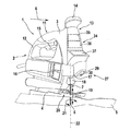
図1は、糸鋸2の形の手持ち式の工作機械1を示し、この工作機械1はケーシング3を有し、ワークピース5上においてベースプレート4を介して摺動可能に支持されている。糸鋸2の作業方向6で前方にある領域において、工作機械1は作業工具7として鋸刃8を有する。この鋸刃8は作業動作時にワークピース5に進入する。
FIG. 1 shows a hand-held machine tool 1 in the form of a thread saw 2, which has a casing 3 and is slidably supported on a
糸鋸2はさらにユーザ側の視界10を有し、この視界10は少なくとも、鋸刃8によって決定される作業領域9の区域にわたり広がっており、また図示されているように、作業状況に関する最善の概観をユーザに伝えるために、作業方向6においてこの作業範囲9を超えた範囲にまで達している。作業領域9および視界10はベースプレート4内の部分として現われるので、作業工具7に関しては視界10の大きさに応じて、鋸刃8を超えるベースプレート4の顕著な突出部が生じる。
The yarn saw 2 further has a user-side field of
糸鋸2のケーシング3は高さ方向において、作業方向6に延びる旋回軸の周りに固定可能に支持されているベースプレート4の反対側に、U字状またはアーチ状の取っ手11を有し、この取っ手11のグリップ部材12は作業方向6に延在しており、且つフロント側でケーシング3の端壁領域13に進入している。これは上方に向かって案内ノブ14に移行する。取っ手11の領域においては下面に係合してグリップ部材12にスイッチ装置15が設けられており、このスイッチ装置15を介して工作機械1がスイッチオンおよびスイッチオフされる。糸鋸2の種々の動作モードをケーシング3の長手側に設けられているスイッチ装置16を介してセットすることができる。
The casing 3 of the yarn saw 2 has a U-shaped or
ケーシング3の端壁領域13は、ベースプレート4に向かって下方に延びており、作業方向6に向かって段付けされている。これによって生じる段17は鋸刃8用の工具収容部18を覆う。鋸刃8は電気駆動式機械としての工作機械1の構成に応じて、矢印19の方向にストローク運動するように駆動される。
The
第1の動作モードは調整作業動作であり、この動作モードにおいては鋸刃8が相対回動不能に作業方向6にアライメントされてストローク方向(矢印19)にのみ駆動される。
The first operation mode is an adjustment work operation. In this operation mode, the saw blade 8 is aligned in the
第2の動作モードはいわゆる振り子ストローク動作であり、この動作モードにおいては鋸刃8が矢印19の方向におけるストローク運動に加えて、鋸刃面を横断する方向に延びる、図示していない旋回軸について旋回可能である。このために設けられている調整駆動部20の一部が図示されている。
The second operation mode is a so-called pendulum stroke operation. In this operation mode, the saw blade 8 extends in a direction transverse to the saw blade surface in addition to the stroke movement in the direction of the
第3の動作モードにおいては、矢印21によって示唆されているように、鋸刃8がストローク運動(矢印19)に加えて、長手軸の方向に延びる回転軸22について調節される。これによって、糸鋸2の長手軸22についての0角度に対応する鋸刃8の真っ直ぐ正面に向けられた状態から、長手軸25に対して角度をなす作業方向に鋸刃8を調整することができる。したがって糸鋸2をいわゆるスクロールジグソーとして使用することができ、また調整が相応に制御されている場合には、糸鋸2は半自動的な糸鋸として動作することができる。半自動的とは、糸鋸2を把持しているユーザは実質的に、その都度の作業方向6に大まかにアライメントされている前方への送りを引き受け、且つ作業動作の結果生じる応答力を支持するだけでよいが、作業線24に正確にアライメントされており、且つこの作業線24に対応する糸鋸2の位置決めは鋸刃8の回転調整によって行われることを意味している。
In the third mode of operation, as suggested by the
さらに糸鋸2には、ワークピース側の参照目印28をセンサにより検出するための手段27が設けられている。これらの参照目印28は、図2および図3において、ワークピース5において光学的に識別可能な目印として、例えば木目32またはワークピース縁部39の形で表されている。センサにより検出するための手段27として、段17によって形成されている移行部内にカメラ29が示唆されているが、相応の領域は他のセンサ装置、例えばラインセンサにも適している。さらに有利にはこの領域内に、必要に応じて、有利には照明装置30またはビーム放射器(Peilstrahler)が設けられている。照明装置は作業領域9および/または視界10における視界状況を改善するために設けられており、またビーム放射器は作業線24への工作機械1のアライメントにおいてそれぞれのユーザのための光学的な方向合わせ支援手段として設けられている。
Further, the yarn saw 2 is provided with
ワークピース側の参照目印28をセンサにより検出するための別の手段27は、ベースプレート4のフロント側において長手軸25の両側に配置されているマウスセンサ31である。
Another means 27 for detecting the workpiece
さらに図1においては、工作機械1に制御手段34、殊に計算ユニット35および制御ユニット36が設けられており、有利には、鋸刃8のその都度の回転位置をセットするためのアクチュエータを含む下位の調整ユニットが設けられていることが概略的に示されている。さらに設けられている表示フィールド37は、殊に工作機械の案内に関する指示、例えば方向指示をユーザに通知するために使用されるが、警告などを指示するためにも使用することができる。表示フィールド37は端壁領域13において、有利には段17の上方に配置されており、この段17に対向して突出しているので、ユーザの直接的な視界内に位置している。
Further, in FIG. 1, the machine tool 1 is provided with control means 34, in particular a
本発明によれば、センサにより検出するための手段27は部分的に異なる態様のもとで使用される。つまりこの手段27は、一方では、ワークピースにおいて工作機械1が追跡する作業軌道41(図3を参照されたい)を検出するために使用され、他方ではこれに応じて、読み込まれた作業軌道41に対応するがマーキングされていない所望の作業線24をワークピース側においてたどる場合には、参照目印(28)としてのワークピース側の目印を検出することによる方向合わせのために使用される。
According to the invention, the
カメラ29を用いて作業される場合には、必要とされる移動データを画像比較によって求めることができ、マウスセンサ31を用いて作業される場合には、ワークピース表面において検出された参照目印、例えば木目32または縁部39から相応の移動データが得られる。
When working with the
追跡する作業軌道を検出して記憶する代わりに、この作業軌道をたどるべき作業線24のための規準として利用できるようにするために、本発明によれば、たどるべき作業線に関する相応の移動データの規準を計算し、プログラミングにより設定することもできる。
In order to be able to use this work trajectory as a criterion for the
またさらにセンサにより検出するための手段27を介して、図3にも示唆されているように、糸鋸2が接触されるべきワークピース5に対する工作機械1、殊に糸鋸2の位置ないし姿勢を検出することができる。図3にはこの状況が図示されており、また明瞭にするために図2と同様に、糸鋸2のベースプレート4のみが示されている。このベースプレート4はワークピース5に対向して配置されているので、ベースプレート4の端面38は差し当たりワークピース5の縁部39と対向している。糸鋸2が作業方向6に向かって前進すると、ベースプレート4はワークピース5に接触し、これにより縁39、またこれに続く他の参照目印、例えば木目31がセンサ手段27の観察領域、殊に最初にマウスセンサ31の観察領域内に現われる。もっとも相応の検出はカメラ29によっても可能である。
Furthermore, the position or attitude of the machine tool 1, in particular the yarn saw 2, with respect to the
したがって、例えば縁部39および/または木目32のような参照目印28に方向が合わせられて、糸鋸2をワークピース5に所期のようにアライメントすることができ、またこのアライメントに応じて、機械側において読み込まれた、またはプログラミングされた作業軌道41に対応し、且つワークピース側の始点40から出発する作業線24をたどることができる。この始点40の位置は機械側において作業軌道41の出発点として鋸刃8の回転軸22に少なくとも近似的に対応する。その種の作業軌道41は図3において例示的に破線で示唆されている。これに対しワークピース側の相応の作業線24は、ワークピース5においてマーキングとして設けられていないが、実線で示唆されている。図3は、縁部39によって表されている参照線を基礎としており、この参照線に対して糸鋸2はその長手軸25でもって垂直に位置している。好適には、参照線としての縁部39へのこのアライメント、またはその都度の他の参照線へのアライメントも、始点40に鋸刃8が接触する際に、例えば表示フィールド37においてユーザに示唆される。
Thus, for example, the edge saw 39 and / or the
ユーザが糸鋸2をワークピース5に近付ける場合、通常は、糸鋸2の所望の作業方向への大まかなアライメント、またその都度の所望の作業方向への大まかなアライメント、または設定された、例えばマーキングされた始点40への大まかなアライメントが行われるだけである。このようにしてワークピース5に非常に接近し、ワークピース5がセンサ手段27の検出領域に入ると、始点40へのアライメントについての偏差が好適には表示フィールド37に示唆され、相応の方向指示が行われる。有利には、相応のことが参照線に対する糸鋸2のアライメントにも該当する。殊に有利には、正確な対応付けがシグナリングされ、場合によっては、対応付けが正確である場合に漸く糸鋸2が解放される。
When the user brings the yarn saw 2 close to the
したがって少なくとも実質的に、糸鋸2の鋸刃8を所期のように始点40に接触させることができ、またこれによって始点40から出発して作業線24にアライメントされた作業が保証され、殊に、鋸刃8を始点40に斜めに接触させることによって補償調整することができる小さなずれを鋸刃8の旋回によって事後的に補償調整することができ、また最初に生じるずれは断面に実質的に影響を及ぼさない。何故ならば、始点40において鋸引きが開始され、そこから鋸刃8の作業線24へのアライメントが行われるからである。
Thus, at least substantially, the saw blade 8 of the yarn saw 2 can be brought into contact with the
その都度の始点40から出発してユーザ案内により、または、半自動的に正確で確実に作業線24をたどることができる本発明の方法によって、ユーザ案内による動作においても、半自動的な動作においても良好な作業結果を達成することができる。ユーザ案内による動作は、鋸刃が回転不能である場合、または場合によっては、鋸刃8が例えば表示フィールド37における案内指示に基づき案内ノブ14を介して手動で旋回可能である場合に行われ、半自動的な動作は、ユーザにより工作機械が支持され、また作業線24の方向に工作機械1が送られる場合、すなわち工作機械1がユーザによって適切に取り扱われる場合での鋸刃8の案内に基づき行われる。
It is possible to start from the
殊に、鋸刃8が回転可能である場合、したがって半自動的な動作の場合には、比較的小さい半径でも鋸引きすることができるので、これによってユーザが糸鋸2の支持またはアライメントにおいて、糸鋸2に合わせられている送り力および/または送り速度を考慮しない危険が増大する。そのような場合に、ワークピース5および/または工具、殊に鋸刃8の損傷を回避するために、好適には、工具の作業速度が送り速度に適応的に適合され、このことは殊に、作業線24のその都度の経過を考慮して行われる。作業速度の適合は、好適には、鋸刃8のストローク数を変更することによって行われる。
In particular, if the saw blade 8 is rotatable, and therefore semi-automatic, it can be sawed even with a relatively small radius, so that the user can support or align the
Claims (15)
工作機械(1)に対して設定される前記作業軌道(41)の特性値を検出して読み込み、該特性値に対応する前記制御信号により、前記作業軌道(41)に対応する、たどるべき作業線(24)をマーキング無しで作業工具(7)に設定することを特徴とする、工作機械の作動方法。 Means for detecting a reference mark (28) representing a work trajectory (41) as a route criterion set on the workpiece side by a sensor and converting a characteristic value corresponding to the reference mark (28) into a control signal by calculation. In the operation method of the machine tool (1) provided with (27),
The characteristic value of the work track (41) set for the machine tool (1) is detected and read, and the work to be traced corresponding to the work track (41) by the control signal corresponding to the characteristic value. A method for operating a machine tool, characterized in that the line (24) is set on the work tool (7) without marking.
経路規準としての作業軌道(41)の特性値を工作機械(1)にプログラミングし、前記特性値に対応する制御信号により、前記作業軌道(41)に対応する、たどるべき作業線(24)をマーキング無しで作業工具(7)に設定することを特徴とする、工作機械の作動方法。 In a method of operating a machine tool (1) comprising means (27) for detecting a reference mark (28) on the workpiece side by a sensor and converting the reference mark (28) into a characteristic value relating to a control signal by calculation,
The characteristic value of the work trajectory (41) as a route criterion is programmed in the machine tool (1), and the work line (24) to be traced corresponding to the work trajectory (41) is controlled by a control signal corresponding to the characteristic value. A method for operating a machine tool, characterized in that the working tool (7) is set without marking.
作業線(24)に沿った送り速度がセンサにより検出され、ストローク運動または回転運動するように駆動される前記作業工具(7)の作業速度が調整される、例えば請求項1または2による工作機械の作動方法において、
前記作業速度を前記送り速度に適応的に適合させることを特徴とする、工作機械の作動方法。 A method for operating a machine tool (1) comprising a work tool (7), comprising:
A machine tool according to claim 1 or 2, for example, wherein the feed rate along the work line (24) is detected by a sensor and the working speed of the working tool (7) driven to stroke or rotate is adjusted. In the operation method of
A method for operating a machine tool, wherein the working speed is adaptively adapted to the feed speed.
ワークピース(5)に対する工作機械(1)の始点(40)の領域においてワークピース側の参照目印(28)を検出し、
前記参照目印(28)によって設定される基準位置に関して、前記ワークピース(5)に対する工作機械(1)の位置を求め、
前記基準位置に対する工作機械(1)の位置を表示する、および/または、追跡すべき作業線(24)に対する工作機械(1)の位置を表示する、および/または、作業線(24)にアライメントされている作業工具(7)の制御を表示することを特徴とする、工作機械の作動方法。 A means (27) and a work tool (7) for detecting a visible reference mark (28) on the workpiece side as a characteristic value by a sensor and converting the characteristic value into a control signal by calculation, for example, In the operating method of the machine tool (1) according to any one of claims 1 to 4,
Detecting a reference mark (28) on the workpiece side in the region of the starting point (40) of the machine tool (1) relative to the workpiece (5);
With respect to the reference position set by the reference mark (28), the position of the machine tool (1) relative to the workpiece (5) is determined,
The position of the machine tool (1) relative to the reference position is displayed and / or the position of the machine tool (1) relative to the work line (24) to be tracked is displayed and / or aligned with the work line (24). A method of operating a machine tool, characterized in that the control of the working tool (7) being displayed is displayed.
ワークピース側におけるそれぞれの始点(40)の領域におけるワークピース側の参照目印(28)を検出し、
前記参照目印(28)に対する工作機械(1)の位置を検出し、
前記始点(40)の領域において、前記参照目印(28)に対する、追跡すべき作業線(24)の位置を検出し、
前記作業線(24)にアライメントされている工作機械(1)の送り方向を求め、
工作機械(1)の送り方向を表示することを特徴とする方法。 The method according to any one of claims 1 to 5, for example the method according to the superordinate concept of claim 5, relating to the alignment on the user side of the machine tool (1) that is adapted to the desired working direction.
Detecting the workpiece side reference mark (28) in the region of the respective starting point (40) on the workpiece side;
Detecting the position of the machine tool (1) relative to the reference mark (28);
Detecting the position of the work line (24) to be tracked with respect to the reference mark (28) in the region of the starting point (40);
Determining the feed direction of the machine tool (1) aligned with the work line (24);
A method characterized by displaying the feed direction of the machine tool (1).
工作機械(1)の作業工具(7)のワークピース側における始点(40)を検出し、
前記始点(40)の領域におけるワークピース側における参照目印(28)を検出し、
前記参照目印(28)に対する工作機械(1)の位置を検出し、
前記始点(40)において、前記参照目印(28)に対する、追跡すべき作業線(24)の位置を検出し、
前記始点(40)において、前記作業線(24)のアライメントに対応する、前記作業工具(7)のアライメントを求め、
求められたアライメントに対応する前記作業工具(7)の制御を実施することを特徴とする方法。 The method according to any one of claims 1 to 6, for example the method according to the superordinate concept of claim 5, relating to the alignment on the user side of the machine tool (1) that is adapted to the desired working direction.
Detecting the starting point (40) on the workpiece side of the work tool (7) of the machine tool (1);
Detecting a reference mark (28) on the workpiece side in the region of the starting point (40);
Detecting the position of the machine tool (1) relative to the reference mark (28);
At the starting point (40), the position of the work line (24) to be tracked with respect to the reference mark (28) is detected;
At the starting point (40), the alignment of the work tool (7) corresponding to the alignment of the work line (24) is obtained,
Controlling the work tool (7) corresponding to the determined alignment.
ワークピース(5)に接触される作業工具(7)に関する作業領域(9)を有し、
前記作業工具(7)の周囲に存在するワークピース側における参照目印(28)をセンサにより検出する光学的な手段(27)を有し、
センサにより検出された前記参照目印(28)に対応する特性値を処理し、該特性値を所定の作業軌道(41)を表す特性値により調整し、読み込まれた、またはプログラミングされた作業軌道(41)に対応する、マーキング無しでたどるべき作業線(24)に前記作業工具(7)がアライメントされるよう工作機械(1)を動作させる制御信号を形成する制御手段(34)を含む計算ユニット(35)および制御ユニット(36)を有することを特徴とする、工作機械。 Machine tool (1) for carrying out the method according to any one of claims 1 to 9,
Having a work area (9) for the work tool (7) in contact with the workpiece (5);
Optical means (27) for detecting a reference mark (28) on the workpiece side existing around the work tool (7) by a sensor;
A characteristic value corresponding to the reference mark (28) detected by the sensor is processed, the characteristic value is adjusted by a characteristic value representing a predetermined work trajectory (41), and a read or programmed work trajectory ( 41. Computation unit comprising control means (34) for generating a control signal for operating the machine tool (1) so that the work tool (7) is aligned with the work line (24) to be followed without marking, corresponding to 41) A machine tool comprising (35) and a control unit (36).
Applications Claiming Priority (1)
| Application Number | Priority Date | Filing Date | Title |
|---|---|---|---|
| DE102008041088A DE102008041088A1 (en) | 2008-08-07 | 2008-08-07 | Method for operating a machine tool, and machine tool therefor |
Publications (2)
| Publication Number | Publication Date |
|---|---|
| JP2010036337A true JP2010036337A (en) | 2010-02-18 |
| JP2010036337A5 JP2010036337A5 (en) | 2012-08-30 |
Family
ID=41129672
Family Applications (1)
| Application Number | Title | Priority Date | Filing Date |
|---|---|---|---|
| JP2009184380A Withdrawn JP2010036337A (en) | 2008-08-07 | 2009-08-07 | Machine tool and operation method of machine tool |
Country Status (4)
| Country | Link |
|---|---|
| US (1) | US20100032178A1 (en) |
| JP (1) | JP2010036337A (en) |
| DE (1) | DE102008041088A1 (en) |
| GB (2) | GB2462372B (en) |
Cited By (7)
| Publication number | Priority date | Publication date | Assignee | Title |
|---|---|---|---|---|
| JP2016168642A (en) * | 2015-03-12 | 2016-09-23 | パナソニックIpマネジメント株式会社 | Cutting tool |
| US10067495B2 (en) | 2011-05-19 | 2018-09-04 | Shaper Tools, Inc. | Automatically guided tools |
| WO2019182046A1 (en) * | 2018-03-22 | 2019-09-26 | 国立大学法人千葉大学 | Wood processing system |
| US10456883B2 (en) | 2015-05-13 | 2019-10-29 | Shaper Tools, Inc. | Systems, methods and apparatus for guided tools |
| US10556356B2 (en) | 2012-04-26 | 2020-02-11 | Sharper Tools, Inc. | Systems and methods for performing a task on a material, or locating the position of a device relative to the surface of the material |
| JP2021501942A (en) * | 2017-11-02 | 2021-01-21 | フェスツール ゲーエムベーハー | Material processing system |
| US11537099B2 (en) | 2016-08-19 | 2022-12-27 | Sharper Tools, Inc. | Systems, methods and apparatus for sharing tool fabrication and design data |
Families Citing this family (4)
| Publication number | Priority date | Publication date | Assignee | Title |
|---|---|---|---|---|
| US8958917B2 (en) * | 1998-12-17 | 2015-02-17 | Hach Company | Method and system for remote monitoring of fluid quality and treatment |
| DE102008055065B4 (en) * | 2008-12-22 | 2021-11-04 | Robert Bosch Gmbh | Hand machine tool device with air guide element |
| DE102013217290B4 (en) | 2013-08-29 | 2020-07-23 | Robert Bosch Gmbh | Hand machine tool information device |
| US10234686B2 (en) * | 2015-11-16 | 2019-03-19 | Microsoft Technology Licensing, Llc | Rainbow removal in near-eye display using polarization-sensitive grating |
Family Cites Families (12)
| Publication number | Priority date | Publication date | Assignee | Title |
|---|---|---|---|---|
| JPS59163608A (en) * | 1983-03-08 | 1984-09-14 | Hitachi Koki Co Ltd | Jigsaw |
| JPS6288545A (en) * | 1985-10-15 | 1987-04-23 | Mitsubishi Heavy Ind Ltd | Method of controlling rotational speed of cutter in end facing machine |
| US5014793A (en) * | 1989-04-10 | 1991-05-14 | Measurement Specialties, Inc. | Variable speed DC motor controller apparatus particularly adapted for control of portable-power tools |
| US5010652A (en) * | 1990-03-19 | 1991-04-30 | Miletich David J | Optically guided power sabre saw |
| JP3506814B2 (en) * | 1995-07-11 | 2004-03-15 | 東芝機械株式会社 | Numerical control unit |
| CA2251526C (en) * | 1997-11-07 | 2006-12-05 | Simonds Industries, Inc. | Method for variably controlling work feed rate for cutting wood, metal and other materials |
| DE202004005478U1 (en) * | 2004-04-02 | 2004-07-15 | Atlas Copco Electric Tools Gmbh | Electrically powered padsaw blade is fixed in variable azimuth -position swivel mount linked to sensor and detector components |
| GB2435189B (en) * | 2004-12-17 | 2010-06-23 | Milwaukee Electric Tool Corp | Saw and Blade with Operational Communication |
| DE102006052808A1 (en) * | 2006-11-09 | 2008-05-15 | Robert Bosch Gmbh | hand-held jigsaw |
| US20080229589A1 (en) * | 2007-03-23 | 2008-09-25 | Danny Bone | Power tool having improved visibility of the cutting area |
| DE102008040064A1 (en) * | 2008-07-02 | 2010-01-07 | Robert Bosch Gmbh | Motorized working device |
| DE102008055057A1 (en) * | 2008-12-22 | 2010-06-24 | Robert Bosch Gmbh | Machine tool, in particular hand-held machine tool |
-
2008
- 2008-08-07 DE DE102008041088A patent/DE102008041088A1/en active Pending
-
2009
- 2009-08-05 US US12/536,130 patent/US20100032178A1/en not_active Abandoned
- 2009-08-05 GB GB0913663.1A patent/GB2462372B/en not_active Expired - Fee Related
- 2009-08-07 JP JP2009184380A patent/JP2010036337A/en not_active Withdrawn
-
2012
- 2012-05-23 GB GB1209808.3A patent/GB2488703B/en not_active Expired - Fee Related
Cited By (14)
| Publication number | Priority date | Publication date | Assignee | Title |
|---|---|---|---|---|
| US10795333B2 (en) | 2011-05-19 | 2020-10-06 | Shaper Tools, Inc. | Automatically guided tools |
| US10067495B2 (en) | 2011-05-19 | 2018-09-04 | Shaper Tools, Inc. | Automatically guided tools |
| US10078320B2 (en) | 2011-05-19 | 2018-09-18 | Shaper Tools, Inc. | Automatically guided tools |
| US10788804B2 (en) | 2011-05-19 | 2020-09-29 | Shaper Tools, Inc. | Automatically guided tools |
| US10556356B2 (en) | 2012-04-26 | 2020-02-11 | Sharper Tools, Inc. | Systems and methods for performing a task on a material, or locating the position of a device relative to the surface of the material |
| JP2016168642A (en) * | 2015-03-12 | 2016-09-23 | パナソニックIpマネジメント株式会社 | Cutting tool |
| US10456883B2 (en) | 2015-05-13 | 2019-10-29 | Shaper Tools, Inc. | Systems, methods and apparatus for guided tools |
| US11537099B2 (en) | 2016-08-19 | 2022-12-27 | Sharper Tools, Inc. | Systems, methods and apparatus for sharing tool fabrication and design data |
| JP2021501942A (en) * | 2017-11-02 | 2021-01-21 | フェスツール ゲーエムベーハー | Material processing system |
| JP7350733B2 (en) | 2017-11-02 | 2023-09-26 | フェスツール ゲーエムベーハー | Part processing system and member processing method |
| JP2019166657A (en) * | 2018-03-22 | 2019-10-03 | 国立大学法人千葉大学 | Wood processing system |
| JP7079443B2 (en) | 2018-03-22 | 2022-06-02 | 国立大学法人千葉大学 | Wood processing system |
| WO2019182046A1 (en) * | 2018-03-22 | 2019-09-26 | 国立大学法人千葉大学 | Wood processing system |
| US11648705B2 (en) | 2018-03-22 | 2023-05-16 | National University Corporation Chiba University | Wood processing system |
Also Published As
| Publication number | Publication date |
|---|---|
| GB0913663D0 (en) | 2009-09-16 |
| GB2488703A (en) | 2012-09-05 |
| GB2462372B (en) | 2013-01-09 |
| GB2488703B (en) | 2013-01-09 |
| GB201209808D0 (en) | 2012-07-18 |
| US20100032178A1 (en) | 2010-02-11 |
| GB2462372A (en) | 2010-02-10 |
| DE102008041088A1 (en) | 2010-02-11 |
Similar Documents
| Publication | Publication Date | Title |
|---|---|---|
| JP2010036337A (en) | Machine tool and operation method of machine tool | |
| US20090025233A1 (en) | Hand-held jigsaw | |
| US20230125519A1 (en) | Automatically guided tools | |
| US20110251727A1 (en) | Motor-driven working device | |
| US9073134B2 (en) | Power tool, particularly a hand-held power tool | |
| US20130019735A1 (en) | Machine Tool, Especially Hand-Held Machine Tool | |
| US20110190936A1 (en) | Portable Power Tool | |
| EP2000243A2 (en) | Power tool having imaging device and display device | |
| US20150059186A1 (en) | Hand-held power tool information device | |
| JP5436545B2 (en) | Machine tools, especially hand-held machine tools | |
| JP2006272469A (en) | Portable cutting tool | |
| JP2010036337A5 (en) | ||
| US8925208B2 (en) | Power tool, in particular a portable power tool | |
| CN112533743B (en) | Hand-held power tool | |
| US20150328736A1 (en) | Hand-Guided Semiautonomous Jigsaw | |
| KR102430841B1 (en) | How to machine a workpiece | |
| US20110173819A1 (en) | Operating method for a power tool, especially a hand-held power tool | |
| EP3067137B1 (en) | Cutting tool | |
| US20120005906A1 (en) | Guiding System for Power Tools | |
| US8714064B2 (en) | Machine tool, particularly a hand-held power tool | |
| JP2010017846A (en) | Apparatus for calibrating machine tool | |
| CN111511513B (en) | Hand-held power tool with a bearing assembly | |
| US20130062087A1 (en) | Machine Tool System, Especially a Jigsaw System | |
| US20110314683A1 (en) | Power Tool, Particularly a Hand-Held Power Tool |
Legal Events
| Date | Code | Title | Description |
|---|---|---|---|
| RD04 | Notification of resignation of power of attorney |
Free format text: JAPANESE INTERMEDIATE CODE: A7424 Effective date: 20101227 |
|
| A521 | Written amendment |
Free format text: JAPANESE INTERMEDIATE CODE: A523 Effective date: 20120713 |
|
| A621 | Written request for application examination |
Free format text: JAPANESE INTERMEDIATE CODE: A621 Effective date: 20120713 |
|
| A761 | Written withdrawal of application |
Free format text: JAPANESE INTERMEDIATE CODE: A761 Effective date: 20120813 |