JP2010033581A - Road-vehicle communication system and optical beacon - Google Patents
Road-vehicle communication system and optical beacon Download PDFInfo
- Publication number
- JP2010033581A JP2010033581A JP2009191064A JP2009191064A JP2010033581A JP 2010033581 A JP2010033581 A JP 2010033581A JP 2009191064 A JP2009191064 A JP 2009191064A JP 2009191064 A JP2009191064 A JP 2009191064A JP 2010033581 A JP2010033581 A JP 2010033581A
- Authority
- JP
- Japan
- Prior art keywords
- information
- vehicle
- distance
- uplink
- road
- Prior art date
- Legal status (The legal status is an assumption and is not a legal conclusion. Google has not performed a legal analysis and makes no representation as to the accuracy of the status listed.)
- Granted
Links
Images


Abstract
Description
本発明は、道路側に設置された光ビーコンと車両に搭載された車載機との間で光信号による双方向通信を行う路車間通信システム、及び、この路車間通信システムに用いることができる光ビーコンに関するものである。 The present invention relates to a road-to-vehicle communication system that performs bidirectional communication using an optical signal between an optical beacon installed on a road side and an in-vehicle device mounted on a vehicle, and light that can be used in the road-to-vehicle communication system. it relates to the beacons.
路車間通信システムを利用した交通情報サービスとして、光ビーコン、電波ビーコン又はFM多重放送を用いたいわゆるVICS(Vehicle Information and Communication System)が既に展開されている。このうち、光ビーコンは近赤外線を通信媒体とした光通信を採用しており、車載機との双方通信が可能となっている。
具体的には、車両の保持するビーコン間の旅行時間情報等を含むアップリンク情報が車載機からインフラ側の光ビーコンに送信され、逆に、渋滞情報、区間旅行時間情報、事象規制情報及び車線通知情報等を含むダウンリンク情報が光ビーコンから車載機に送信されるようになっている(例えば、特許文献1参照)。
As a traffic information service using a road-to-vehicle communication system, so-called VICS (Vehicle Information and Communication System) using optical beacons, radio wave beacons or FM multiplex broadcasting has already been developed. Among these, the optical beacon employs optical communication using near infrared rays as a communication medium, and enables two-way communication with the in-vehicle device.
Specifically, uplink information including travel time information between beacons held by the vehicle is transmitted from the in-vehicle device to the optical beacon on the infrastructure side, and conversely, traffic jam information, section travel time information, event regulation information, and lanes Downlink information including notification information and the like is transmitted from the optical beacon to the vehicle-mounted device (see, for example, Patent Document 1).
上記光ビーコンは、車載機との間で双方向通信を行うビーコンヘッド(投受光器)を備えており、この投受光器は、ダウンリンク情報を送出する発光ダイオード(LED)と、車載機からのアップリンク情報を受信するフォトセンサとを備えている。
例えば図11に示すように、光ビーコン104のビーコンヘッド(投受光器)108は、その直下よりも上流側よりに通信領域Aが設定されている。光ビーコン(光学式車両感知器)104の「近赤外線式インタフェース規格」によれば、アップリンク領域UAは、ダウンリンク領域DAの車両進行方向の上流部分(図11の右側部分)と重複しており、ダウンリンク領域DAとアップリンク領域UAの上流端は互いに一致するものとされている。また、実際に、現在設定されているダウンリンク領域DAの上流端は、アップリンク領域UAの上流端cよりも上流側(例えば、図11のc′)に設定されている場合が多い。
The optical beacon includes a beacon head (projector / receiver) that performs bidirectional communication with an in-vehicle device. The projector / receiver includes a light-emitting diode (LED) that transmits downlink information and an in-vehicle device. And a photo sensor for receiving the uplink information.
For example, as shown in FIG. 11, the communication area A of the beacon head (projector / receiver) 108 of the
従って、ダウンリンク領域DAの車両進行方向長さは通信領域A全体の同方向長さと一致する。また、上記規格によれば、一般道向けの光ビーコン104の場合で、ダウンリンク領域DAの下流端aは、ビーコンヘッド108の直下の1.0〜1.3m上流側に位置し、ダウンリンク領域DAの下流端aからアップリンク領域UAの下流端bまでの距離は2.1mと規定され、アップリンク領域UAの下流端bから同領域UAの上流端cまでの距離は1.6mと規定されている。従って、この場合、通信領域Aの車両進行方向の全長は3.7mとなる。
Therefore, the vehicle traveling direction length of the downlink area DA matches the same direction length of the entire communication area A. Further, according to the above standard, in the case of the
上記路車間通信システムでは、光ビーコン104と車載機102との間で次のような通信が行われる。まず、光ビーコン104は、最初に、車線通知情報(車両ID無し)を含む第1のダウンリンク情報を道路のダウンリンク領域DAに所定の送信周期で常時送信する。
このダウンリンク領域DAに車両が進入することで、その車両に搭載された車載機102の投受光器(車載ヘッド)が第1のダウンリンク情報を受信すると、当該車載機102は、自己の車両IDを格納した車線通知情報を含むアップリンク情報の送信を開始する。
そして、上記アップリンク情報を光ビーコン104のビーコンヘッド108が受信すると、光ビーコン104は、ダウンリンクの切り替えを行い、車載機102に対して上記車両IDを有する車線通知情報を含む第2のダウンリンク情報の送信を開始する。この第2のダウンリンク情報は、所定時間内において可能な限り繰り返し送信され、車載機102において受信される。
In the road-to-vehicle communication system, the following communication is performed between the
When the vehicle enters the downlink area DA and the projector / receiver (vehicle-mounted head) of the vehicle-mounted
Then, when the
このような光ビーコンを用いた路車間通信システムにより、例えば、通信領域A内の特定位置(例えば車両進行方向の上流端)を車両(車載機102)の位置と見立て、当該特定位置からその下流側の所定位置P0(例えば、信号機の手前に設けられた停止線40)までの「距離情報」を第2のダウンリンク情報に含ませておき、この距離情報を受信した車載機102により、当該距離情報を利用して、停止線40の手前で強制停止するように車両を制動させたり、ドライバに停止や減速を促す報知を行ったりして、ドライバに対して安全運転支援を行う場合がある(例えば、本願出願人が提案した特願2006−121692号及び特願2006−121700号)。
By such a road-to-vehicle communication system using an optical beacon, for example, a specific position in the communication area A (for example, the upstream end in the vehicle traveling direction) is regarded as the position of the vehicle (onboard unit 102), and the downstream from the specific position. The “distance information” to the predetermined position P0 on the side (for example, the
しかし、このような安全運転支援を行う場合、次のような問題がある。
現在、実際に運用されている光ビーコン104の通信領域A、特にアップリンク領域UAは、車載機102からのアップリンク情報をより確実に受信するため、例えば図11に仮想線で示すように、前記規格で規定された正式な領域よりもかなり広い領域(例えば、△db′c′で示す領域)になっていることが多い。同様に、ダウンリンク領域DAについても前記規格の領域よりも設定されている場合が多い。
このように通信領域Aが正式な領域よりも広範であると、「距離情報」の始点となる通信領域A内の特定位置と、車両が前記距離情報を受信した時点における実際の位置との差が大きくなってしまう可能性が高く、距離情報の精度が低下する。このため、この距離情報を利用した安全運転支援の精度も同じように低下することになり、例えば、安全運転支援機能によって、停止線40の手前に停止させるように車両を制動したにも関わらず、停止線40をオーバーして車両が停止するといった事態が起こりうる。
However, when such safe driving support is performed, there are the following problems.
Currently, the communication area A of the
Thus, if the communication area A is wider than the official area, the difference between the specific position in the communication area A that is the starting point of the “distance information” and the actual position when the vehicle receives the distance information Is likely to increase, and the accuracy of the distance information decreases. For this reason, the accuracy of the safe driving support using the distance information is similarly reduced. For example, although the vehicle is braked so as to stop before the
そこで、アップリンク領域を車両進行方向に複数の分割領域に分割し、各分割領域に対応してアップリンク情報を受信する複数の受信部を投受光器に設けることより、アップリンク領域を構成する個々の分割領域を車両進行方向に狭く設定することが考えられる。Therefore, the uplink region is configured by dividing the uplink region into a plurality of divided regions in the vehicle traveling direction, and providing the projector / receiver with a plurality of receiving units that receive uplink information corresponding to each divided region. It can be considered that each divided region is set narrow in the vehicle traveling direction.
この場合、アップリンク情報を受信した後の所定のダウンリンク情報に、アップリンク情報を受信した受信部に対応する分割領域内の位置からその下流側の所定位置までの距離に関する距離情報を含ませるようにすれば、車載機において所定位置までの正確な距離を認識させることが可能となる。In this case, the predetermined downlink information after receiving the uplink information includes distance information related to the distance from the position in the divided region corresponding to the receiving unit that has received the uplink information to the predetermined position downstream thereof. If it does in this way, it will become possible to make it recognize the exact distance to a predetermined position in vehicle equipment.
しかし、上記のようにアップリンク領域を車両進行方向に分割した分割領域に対応して複数の受信部を設ける場合(以下、「PD分割タイプ」ということがある。)において、車両が分割領域の境界線(境界部)付近を走行しているときに、車載機からアップリンク情報が送信されると、当該境界線を跨ぐ2つの分割領域に対応した2つの受信部が当該アップリンク情報を同時に受信しまう可能性がある。However, in the case where a plurality of receiving units are provided corresponding to the divided areas obtained by dividing the uplink area in the vehicle traveling direction as described above (hereinafter sometimes referred to as “PD division type”), the vehicle is divided into the divided areas. When uplink information is transmitted from the in-vehicle device while traveling in the vicinity of the boundary line (boundary part), the two reception units corresponding to the two divided regions straddling the boundary line simultaneously transmit the uplink information. There is a possibility of receiving.
この場合、アップリンク情報を受信した受信部を1つに特定できないため、アップリンク情報の送信位置と推定すべき距離情報の上流端を特定できず、距離情報を生成できないという不都合が生じる。In this case, since it is not possible to specify one receiving unit that has received the uplink information, it is not possible to specify the upstream position of the distance information to be estimated as the transmission position of the uplink information, resulting in inconvenience that the distance information cannot be generated.
本発明は、このような実情に鑑み、PD分割タイプの光ビーコン及びこれを用いた路車間通信システムにおいて、互いに隣接又は重複する2つの分割領域に対応する2つの受信部がアップリンク情報を同時に受信しても、アップリンク情報の送信位置を決定できるようにすることを目的とする。 In the present invention, in view of such a situation, in a PD division type optical beacon and a road-to-vehicle communication system using the same, two reception units corresponding to two division regions adjacent to or overlapping each other simultaneously transmit uplink information. It is an object to be able to determine the transmission position of uplink information even if it is received .
本発明の路車間通信システムは、アップリンク情報を受信可能なアップリンク領域とダウンリンク情報を送信可能なダウンリンク領域とからなる通信領域が道路の所定範囲に設定された投受光器を有する光ビーコンと、車両に搭載されるとともに、前記通信領域において前記投受光器との間で前記アップリンク情報及び前記ダウンリンク情報の送受信を行う車載機と、を備えている路車間通信システムであって、前記アップリンク領域が、車両進行方向に複数の分割領域に分割され、前記投受光器が、前記各分割領域に対応して前記アップリンク情報を受信する複数の受信部を有していることを特徴とする。 The road-to-vehicle communication system of the present invention includes a light having a light emitter / receiver in which a communication region including an uplink region capable of receiving uplink information and a downlink region capable of transmitting downlink information is set to a predetermined range of a road. A road-to-vehicle communication system comprising a beacon and an in-vehicle device that transmits and receives the uplink information and the downlink information to and from the projector / receiver in the communication area. The uplink area is divided into a plurality of divided areas in the vehicle traveling direction, and the projector / receiver has a plurality of receiving units for receiving the uplink information corresponding to the divided areas. It is characterized by.
また、本発明の光ビーコンは、アップリンク情報を受信可能なアップリンク領域とダウンリンク情報を送信可能なダウンリンク領域とからなる通信領域が道路の所定範囲に設定された投受光器を有する光ビーコンであって、前記アップリンク領域が、車両進行方向に複数の分割領域に分割され、前記投受光器が、前記各分割領域に対応して前記アップリンク情報を受信する複数の受信部を有していることを特徴とする。 Further, the light beacon of the present invention comprises a projector-receiver communication area consisting of a transmittable downlink section the possible uplink region and the down link information receive uplinks information is set to a predetermined range of the road An optical beacon, wherein the uplink region is divided into a plurality of divided regions in a vehicle traveling direction, and the light receiver / receiver includes a plurality of receiving units that receive the uplink information corresponding to the divided regions. It is characterized by having.
また、これらの場合、上記路車間通信システム及び光ビーコンは、前記受信部によって前記アップリンク情報を受信した後に所定のダウンリンク情報を前記投受光器に送信させる通信制御部を有しており、互いに隣接する2つの分割領域に対応する2つの受信部によって前記アップリンク情報が同時に受信されたとき、前記所定のダウンリンク情報は、当該2つの分割領域における境界部から前記所定位置までの距離に関する距離情報を含んでいる。 Further, in these cases, the road-to-vehicle communication system and the optical beacon have a communication control unit that transmits predetermined downlink information to the projector / receiver after receiving the uplink information by the receiving unit, When the uplink information is simultaneously received by two receiving units corresponding to two adjacent divided areas, the predetermined downlink information relates to a distance from a boundary portion to the predetermined position in the two divided areas. Contains distance information.
或いは、上記路車間通信システム及び光ビーコンにおいて、前記アップリンク領域が、車両進行方向に隣接する他の分割領域と重複する領域を有する分割領域を含み、互いに重複する2つの分割領域に対応する2つの受信部によって前記アップリンク情報が同時に受信されたとき、前記所定のダウンリンク情報は、当該2つの分割領域における重複領域内の位置から前記所定位置までの距離に関する距離情報を含んでいる。Alternatively, in the road-to-vehicle communication system and the optical beacon, the uplink region includes a divided region having a region overlapping with another divided region adjacent in the vehicle traveling direction, and corresponds to two divided regions overlapping each other. When the uplink information is received simultaneously by two receiving units, the predetermined downlink information includes distance information related to a distance from a position in the overlapping area in the two divided areas to the predetermined position.
上記路車間通信システム及び光ビーコンによれば、2つの受信部がアップリンク情報を同時に受信した場合でも、境界部や重複領域内の位置を上流端とした距離情報を所定のダウンリンク情報に含めるので、その上流端によってアップリンク情報の送信位置を決定することができ、車両側に提供する距離情報を生成可能となる。According to the road-to-vehicle communication system and the optical beacon, even when two receivers receive uplink information at the same time, distance information with the position in the boundary or overlapping area as the upstream end is included in the predetermined downlink information Therefore, the transmission position of the uplink information can be determined by the upstream end, and the distance information provided to the vehicle side can be generated.
上記の場合、光ビーコンは、アップリンク情報を同時に受信した2つの受光部の受光レベルに基づいて、前記境界部や前記重複領域における前記車両の位置を推定する推定部を有し、前記所定のダウンリンク情報が、前記推定部によって推定された前記車両の位置に関する情報を含んでいることが好ましい。
この場合、推定部によって推定された車両の位置に関する情報から距離情報をより正確に設定することが可能となる。
In the above case, the optical beacon has an estimation unit that estimates the position of the vehicle in the boundary portion or the overlapping region based on the light reception levels of the two light reception units that have received uplink information at the same time. It is preferable that the downlink information includes information on the position of the vehicle estimated by the estimation unit.
In this case, it becomes possible to set the distance information more accurately from the information related to the position of the vehicle estimated by the estimation unit.
本発明によれば、PD分割タイプの光ビーコン及びこれを用いた路車間通信システムにおいて、互いに隣接又は重複する2つの分割領域に対応する2つの受信部がアップリンク情報を同時に受信しても、アップリンク情報の送信位置を決定することができる。 According to the present invention, in a PD split type optical beacon and a road-to-vehicle communication system using the same, even if two receiving units corresponding to two divided areas adjacent to each other receive uplink information at the same time, The transmission position of the uplink information can be determined .
以下に説明する第1〜第4実施形態のうち、2つの受信部が同時にアップリンク情報を受信する場合(第2及び第3実施形態)のみが、本発明に関連する実施形態である。
〔第1の実施形態〕
〔システムの全体構成〕
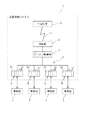
図1は、第1実施形態に係る路車間通信システムの全体構成を示すブロック図である。
図1に示すように、この路車間通信システムは、インフラ側の交通管制システム1と、道路Rを走行する各車両Cに搭載された車載機2とを備えて構成されている。
交通管制システム1は、管制室に設けられた中央装置3と、道路Rの各所に多数設置された光ビーコン(光学式車両感知器)4と、を有している。光ビーコン4は、近赤外線を通信媒体とした光通信によって車載機2との間で双方向通信を行う。なお、中央装置3は交通管制室に設けられている。
Of the first to fourth embodiments described below, only when the two receiving units simultaneously receive uplink information (second and third embodiments) is an embodiment related to the present invention.
[First Embodiment]
[Overall system configuration]
FIG. 1 is a block diagram showing the overall configuration of the road-vehicle communication system according to the first embodiment.
As shown in FIG. 1, the road-to-vehicle communication system includes an infrastructure-side traffic control system 1 and an in-
The traffic control system 1 includes a
〔光ビーコンの構成〕
光ビーコン4は、電話回線等の通信回線5を介して中央装置3と接続された通信インタフェースである通信部6と、この通信部6が接続されたビーコン制御機7と、このビーコン制御機7のセンサ用インタフェースに接続された複数(図例では4つ)のビーコンヘッド(投受光器)8とを備えている。
各ビーコンヘッド8は、筐体の内部に発光ダイオード(LED)10、フォトセンサ(受信部)11を収納して構成されている(図3参照)。このうち、LED10は、近赤外線よりなるダウンリンク情報を後述する通信領域Aに発光し、フォトセンサ11は、車載機2からの近赤外線よりなるアップリンク情報を受光する。また、本実施形態のビーコンヘッド8には、複数(4つ)のフォトセンサ11が設けられている。
[Configuration of optical beacon]
The
Each
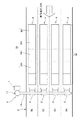
図2は、上記光ビーコン4の平面図である。図2に示すように、本実施形態の光ビーコン4は、同じ方向の複数(図例では4つ)の車線R1〜R4を有する道路Rに設置されており、各車線R1〜R4に対応して設けられた前記複数のビーコンヘッド8と、これらビーコンヘッド8を一括制御する制御部である一台の前記ビーコン制御機7とを備えている。
上記ビーコン制御機7は、CPU、メモリ(RAM)及び記憶装置(ROM)を有するプログラマブルなマイコンよりなり、通信部6(図1)による中央装置3との双方向通信と、ビーコンヘッド8による車載機2との路車間通信を行う通信制御部としての機能を有する。なお、このビーコン制御機7による路車間通信の内容については後述する。
FIG. 2 is a plan view of the
The
ビーコン制御機7は、道路脇に立設した支柱13に設置されており、各ビーコンヘッド8は、支柱13から道路R側に水平に架設した架設バー14に取り付けられ、道路Rの各車線R1〜R4の直上に配置されている。
各ビーコンヘッド8のLED10は、各車線R1〜R4の直下よりも車両進行方向の上流側に向けて近赤外線を発光しており、これにより、車載機2との間で路車間通信を行うための通信領域Aが当該ヘッド8の上流側に設定されている。
The
The
〔通信領域について〕
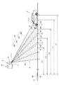
図3は、光ビーコン4の通信領域Aを示す側面図である。
図3に示すように、光ビーコン4の通信領域Aは、車載機2の投受光器である車載ヘッド27がダウンリンク情報を受信することができるダウンリンク領域(図3において実線のハッチングを設けた領域)DAと、光ビーコン4のビーコンヘッド8が車載ヘッド27からのアップリンク情報を受信することができるアップリンク領域(図3において破線のハッチングを設けた領域)UAとからなる。
[About communication area]
FIG. 3 is a side view showing the communication area A of the
As shown in FIG. 3, the communication area A of the
ダウンリンク領域DAは、ビーコンヘッド8の投受光位置d、道路R上の位置a及びcを頂点とする△dacで示された範囲に設定されている。また、アップリンク領域UAは、前記位置dと、道路R上の位置b及びcを頂点とする△dbcで示された範囲に設定されている。したがって、ダウンリンク領域DAとアップリンク領域UAの上流端cは互いに一致し、アップリンク領域UAは、ダウンリンク領域DAの車両進行方向の上流部分(図3の右側部分)と重複している。また、ダウンリンク領域DAの車両進行方向長さは通信領域A全体の同方向長さと一致している。
The downlink area DA is set in a range indicated by Δdac having apexes at the light emitting / receiving position d of the
光ビーコン(光学式車両感知器)4の「近赤外線式インタフェース規格」によれば、ダウンリンク領域DA及びアップリンク領域UAの正式な領域寸法が規定されている。この規定では、一般道向けの光ビーコン4の場合で、ダウンリンク領域DAの下流端aは、ビーコンヘッド8の直下の1.0〜1.3m上流側に位置し、ダウンリンク領域DAの下流端aからアップリンク領域UAの下流端bまでの距離は2.1mと規定されている。また、アップリンク領域UAの下流端bから同領域UAの上流端cまでの距離は1.6mと規定されている。したがって、正式な通信領域Aの車両進行方向の全長(ac間の長さ)は3.7mとなる。
According to the “near infrared interface standard” of the optical beacon (optical vehicle sensor) 4, the formal area dimensions of the downlink area DA and the uplink area UA are defined. In this rule, in the case of an
しかしながら、本実施形態では、アップリンク領域UAの下流端bから同領域UAの上流端cまでの距離は、上記規定よりも上流側及び下流側へ長く設定されている。その結果、アップリンク領域UAは上記規定よりも車両進行方向に広がり、同時にダウンリンク領域DAも上記規定よりも車両進行方向に広がっている。
このようにアップリンク領域UA及びダウンリンク領域DAが広くなると、車載機2と光ビーコン4との間のアップリンク情報及びダウンリンク情報の送受信の確実性が増すことになる。
However, in this embodiment, the distance from the downstream end b of the uplink area UA to the upstream end c of the area UA is set longer to the upstream side and the downstream side than the above definition. As a result, the uplink area UA extends in the vehicle traveling direction from the above definition, and the downlink area DA also extends in the vehicle traveling direction from the above definition.
Thus, when the uplink area UA and the downlink area DA are widened, the certainty of transmission / reception of uplink information and downlink information between the in-
さらに、アップリンク領域UAは、車両進行方向に複数に分割されている。具体的にアップリンク領域UAは、位置dを上端とし、道路R上の位置e1〜e3を下端とする3本の境界線(境界部)Kによって4つに分割されている。
ビーコンヘッド8に設けられた4つのフォトセンサ11(図1)は、それぞれアップリンク領域UAの各分割領域UA1〜UA4を受信領域としている。したがって、例えば分割領域UA1内で車載ヘッド27から発信されたアップリンク情報は、この分割領域UA1に対応するフォトセンサ11によって受信される。
Further, the uplink area UA is divided into a plurality in the vehicle traveling direction. Specifically, the uplink area UA is divided into four by three boundary lines (boundary portions) K having a position d as an upper end and positions e1 to e3 on the road R as lower ends.
The four photosensors 11 (FIG. 1) provided in the
〔車載機及び車両の構成〕
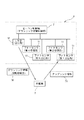
図4は、光ビーコン4と路車間通信する前記車載機2と、この車載機2が搭載された車両Cの概略構成図である。
図4に示すように、この車両Cは、ドライバの搭乗席(図示せず)を有する車体21と、この車体21に搭載された前記車載機2と、車両Cの各部を統合制御する電子制御装置(ECU)22と、車体21を駆動するエンジン23と、車体21を制動するブレーキ装置24と、車両Cの現時の速度を常時検出している速度検出器25とを備えている。ECU22は、ドライバのアクセル操作に基づくエンジン23の駆動制御や、ブレーキ操作に基づく制動制御等、車両Cに対する各種の制御を行う。
[Configuration of in-vehicle device and vehicle]
FIG. 4 is a schematic configuration diagram of the in-
As shown in FIG. 4, the vehicle C includes a
車載機2は、車載コンピュータ26と、このコンピュータ26のセンサ用インタフェースに接続された車載ヘッド(投受光器)27と、搭乗席のドライバに対するヒューマンインタフェースとしてのディスプレイ28及びスピーカ装置29とを備えている。
上記車載ヘッド27は、光ビーコンの投受光器8と同様に、発光ダイオード(LED)とフォトセンサを備えている(図示せず)。このうち、LEDは、近赤外線よりなるアップリンク情報を発光し、フォトセンサは、通信領域Aに発光された近赤外線よりなるダウンリンク情報を受光する。
The in-
The vehicle-mounted
車載コンピュータ26は、CPU、メモリ(RAM)及び記憶装置(ROM)を有するプログラマブルなマイコンよりなり、車載ヘッド27による光ビーコン4との路車間通信の制御処理を行う。
また、車載コンピュータ26は、所定の各機能を実行するプログラムを記憶装置に格納しており、このプログラムが実行する機能部として、距離認識部30、補正部31及び支援制御部32を備えている。なお、これらの各機能部30,31,32の処理内容については後述する。
The in-
The in-
〔路車間通信の内容〕
図5は、通信領域Aにおいて、ビーコンヘッド8と車載ヘッド27との間で行われる双方向での路車間通信の手順を示している。以下、図5を参照しつつ、本実施形態の路車間通信の内容を説明する。
まず、光ビーコン4のビーコン制御機7は、各車線R1〜R4に対応するビーコンヘッド8から、ダウンリンクの切り替え前の第1情報として、車線通知情報を含む第1のダウンリンク情報34を、各車線R1〜R4のダウンリンク領域DAに所定の送信周期で常に送信し続けている(図5のF1)。なお、この段階では、車線通知情報には未だ車両IDは格納されていない。
[Contents of road-to-vehicle communication]
FIG. 5 shows a two-way road-to-vehicle communication procedure performed between the
First, the
車載機2を搭載した車両Cが実際のダウンリンク領域DAに進入すると、車載機2の車載ヘッド27が車線通知情報(車両ID無し)を含む第1のダウンリンク情報34を受信する。
この際、車載機2の車載コンピュータ26は、当該車両Cが実際の通信領域A内に存在していることを認識する。その後、車載コンピュータ26は、アップリンク情報35の送信を開始し(図5のF2)、このアップリンク情報35をビーコンヘッド8に対して所定の送信周期(アップリンク送信周期)で送信する(図5のF3)。
When the vehicle C equipped with the in-
At this time, the in-
車載コンピュータ26は、車両Cに特定の車両IDを上記アップリンク情報35に格納して当該アップリンク情報35を送信し、ビーコン間の旅行時間情報を有している場合には、この情報もアップリンク情報35に含ませる。また、車載コンピュータ26は、光ビーコン4のビーコン制御機7がダウンリンクの切り替えを行ったことを認識するまで、当該アップリンク情報35を送信し続ける。
The in-
一方、光ビーコン4のビーコンヘッド8がアップリンク情報35受信すると(図5のF4)、ビーコン制御機7は、ダウンリンクの切り替えを行い、第2情報として、車両ID情報を有する車線通知情報を含む第2のダウンリンク情報36の送信を開始し(図5のF5)、この第2のダウンリンク情報36の送信を所定時間内において可能な限り繰り返す(図5のF6)。
On the other hand, when the
上記車線通知情報には、車線R1〜R4(図2)ごとに車両IDを格納するフィールドがあり、各車両IDに対して車線番号を付与することができる。このため、異なる車線R1〜R4を走行する各車両Cの車載コンピュータ26は、その格納フィールド内のいずれに自車両の車両IDが含まれるかを判断することにより、自車両がどの車線R1〜R4を走行しているかを認識できる。
The lane notification information includes a field for storing a vehicle ID for each lane R1 to R4 (FIG. 2), and a lane number can be assigned to each vehicle ID. For this reason, the in-
第2のダウンリンク情報36には、車両IDを含む車線通知情報の他に、渋滞情報、区間旅行時間情報、事象規制情報、及び、ドライバに対する安全運転支援のための支援情報等が含まれている。
この支援情報には、光ビーコン4より下流側の信号機の灯色が変わるタイミング情報である信号情報の他、通信領域Aからその下流側の所定位置(例えば、停止線)までの長さ情報である距離情報等が含まれている。
The
This support information includes signal information that is timing information for changing the color of the traffic light downstream from the
図5に示すように、第2のダウンリンク情報36は、単一又は複数の最小フレーム37で構成されている。前記「近赤外線式インタフェース規格」によれば、この最小フレーム37のデータ量は合計128バイトと規定され、ヘッダ部38に5バイト、実データ部39に123バイトが割り当てられている。
前記規格によれば、第2のダウンリンク情報36は、1〜80個の最小フレーム37で構成することができ、送信可能時間は250msに設定されている。また、このダウンリンク情報36は送信すべき情報量に対応した任意数の最小フレーム37で構成され、上記送信可能時間の範囲内で繰り返し送信される。
As shown in FIG. 5, the
According to the standard, the
最小フレーム37の送信周期は約1msである。従って、例えば、三つの最小フレーム37で一つのダウンリンク情報36を構成する場合には、ダウンリンク情報36の送信周期は約3msになるので、当該ダウンリンク情報36は所定の送信可能時間(250ms)の間に約80回繰り返して送信されることになる。
車載機2の車載コンピュータ26は、第2のダウンリンク情報36を受信した時点(図6のF7)で光ビーコン4でのダウンリンクの切り替えを認識し、この時点でアップリンク情報35の送信を停止する。
The transmission period of the
The in-
本実施形態の路車間通信システムは、図3に示すように、通信領域Aからその下流側の所定位置P0までの距離を認識して位置標定を行い(図5のF8)、これに基づいて、ドライバに対する安全運転支援を行う距離認識システムとして機能している。
以下、前記した距離情報の内容と、これに基づいて車載機2が行う安全運転支援のための距離認識について説明する。
As shown in FIG. 3, the road-to-vehicle communication system according to the present embodiment recognizes the distance from the communication area A to the predetermined position P0 on the downstream side, and performs position location (F8 in FIG. 5). It functions as a distance recognition system that provides safe driving support to the driver.
Hereinafter, the content of the distance information described above and distance recognition for safe driving support performed by the vehicle-mounted
〔距離情報の内容〕
図3に示すように、光ビーコン4のビーコン制御機7は、通信領域Aの所定位置P1〜P4からその下流側の所定位置P0までの距離L1〜L4の数値である前記距離情報を予め記憶装置に記憶している。そして、この距離L1〜L4についての距離情報を第2のダウンリンク情報36の送信フレームに格納して、当該フレームをビーコンヘッド8から繰り返し送出する。
距離L1〜L4の下流端(終点)P0は、光ビーコン4の下流側に設置された、例えば信号機手前の停止線40の位置に設定されている。また、距離L1〜L4の上流端(始点)P1〜P4は、アップリンク領域UAの各分割領域UA1〜UA4に応じて4カ所に設定されている。具体的に上流端P1〜P4の位置は、各分割領域UA1〜UA4における道路R上の車両進行方向の略中央位置に設定されている。
[Contents of distance information]
As shown in FIG. 3, the
The downstream end (end point) P0 of the distances L1 to L4 is set, for example, at the position of the
ビーコン制御機7は、予め記憶した複数の距離L1〜L4についての距離情報のうちいずれかを選択し、第2のダウンリンク情報36の送信フレームに格納する。そして、どの距離L1〜L4を選択するかは、ダウンリンクの切り換え前にアップリンク情報を受信したフォトセンサ11に基づいて決定される。
例えば、最上流側の分割領域UA1において、道路R上を走行している車両Cの車載ヘッド27がアップリンク情報35を送信し、図6に示すように、この分割領域UA1に対応するフォトセンサ(第1受信部)11が当該アップリンク情報35を受信した場合、ビーコン制御機(ダウンリンク切り替え制御部)7は、アップリンク情報35を受信したフォトセンサ11を特定し、それに対応する距離情報L1を選択するとともに、ダウンリンクを切り換え、LED10を介して距離L1についての距離情報を含む第2のダウンリンク情報36を送信する。
The
For example, in the uppermost divided area UA1, the in-
他の分割領域UA2〜UA4に対応するフォトセンサ(第2〜第4受信部)11のいずれかがアップリンク情報35を受信した場合は、ビーコン制御機7は、上流点がP2〜P4となるいずれかの距離L2〜L4を選択し、当該距離L2〜L4についての距離情報を含む第2のダウンリンク情報36を送信する。
When any of the photosensors (second to fourth receiving units) 11 corresponding to the other divided areas UA2 to UA4 receives the
〔距離認識(安全運転支援)の内容〕
図4に示すように、上記距離情報を含む第2のダウンリンク情報36を車載ヘッド27が受信すると、車載コンピュータ26の距離認識部30は、そのダウンリンク情報36のフレームに含まれている距離情報を抽出して、前記距離L1〜L4を認識する。
そして、車載コンピュータ26の支援制御部32は距離L1〜L4を利用して、ドライバに対する安全運転支援を行う。
[Contents of distance recognition (safe driving support)]
As shown in FIG. 4, when the in-
And the
例えば、支援制御部32は、停止線40までの距離L1〜L4と現時点の車両Cの走行速度とから、その停止線40の手前で停止するための減速度(負の加速度)を算出し、その減速度をECU22に通知する。ECU22は、当該減速度となるようにブレーキ装置24を作動させ、これにより、車両Cを停止線40の手前で自動停止させることができる。
For example, the
また、支援制御部32の安全運転支援としては、ディスプレイ28やスピーカ装置29を用いたドライバに対する注意喚起であってもよい。
例えば、支援制御部32により、停止線40までの距離L1をディスプレイ28に表示させてもよい。また、現時の車両Cの走行速度が速すぎる場合には、支援制御部32により、停車や減速を促す注意喚起をディスプレイ28に表示させたり、その注意喚起をスピーカ装置29から音声出力させたりしてもよい。
Further, the safe driving support of the
For example, the distance L1 to the
また、支援制御部32は、前記距離情報と共に、第2のダウンリンク情報に含まれる信号情報を用いて安全運転支援を行うこともできる。
ここで、信号情報とは、交通信号機が表示する現在又は将来の信号灯色に関する情報を指し、各信号灯色の表示継続予定期間や表示する順序等に関する情報(表示予定情報)等を含む。例えば、「現在灯色が青信号で継続予定時間が5秒であり、次の灯色が黄信号で継続予定時間が8秒であり、その次の灯色が右折青矢印灯で継続予定時間10秒である」といった情報である。
Moreover, the
Here, the signal information refers to information related to the current or future signal lamp color displayed by the traffic signal device, and includes information (display schedule information) regarding the display continuation period of each signal lamp color, the display order, and the like. For example, “the current lamp color is blue and the scheduled duration is 5 seconds, the next lamp color is yellow and the scheduled duration is 8 seconds, and the next lamp color is a right turn blue arrow lamp and the scheduled duration is 10 seconds. It is information such as “second”.
この信号情報を受信した車載コンピュータ27の支援制御部32は、停止線40までの距離L1〜L4(前述の距離情報)と車両Cの走行速度や加速度等から、停止線40に到着するまでの所要時間を推定した上で、当該所要時間経過後の信号灯色を推定することができる。そして、例えば、現在の信号灯色は青信号であるが、停止線40に到着する時点で信号灯色が赤信号と予測されるような場合には、安全に停止線40の手前で停止することができるように、車両Cを制動するための制御を行う。逆に、減速しなければ安全に交差点を通過できると判断できるような場合には、車両Cの速度を維持するための制御を行うことができる。
The
車両Cを制動したり速度を維持したりするため、支援制御部32は、車両のブレーキ装置24(図4)やアクセルに対して直接的に制御を行ってもよい。また、支援制御部32では単に制動や速度維持に関する情報を生成し、その情報をECU22に通知することによってECU22でブレーキ装置24やアクセルを制御するものであってもよい。すなわち、支援制御部32は、間接的な制御を行うものであってもよい。
In order to brake the vehicle C or maintain the speed, the
また、支援制御部32は、車載装置の主導による制御のみならず、ブレーキアシストなど、ドライバの運転動作を補助する動作をしても良い。
In addition, the
支援制御部32は、車両Cの搭乗者に対して、信号灯色の推定の結果を音声や画像情報によって通知するようにしても良い。例えば、「間もなく信号が変わるので停止すべきである」といった内容の音声をスピーカ装置29からドライバに向けて発したり、ヘッドアップディスプレイやナビゲーション装置等のディスプレイ28に文字や図柄で表示したりすることができる。
安全運転の支援については、不適切なタイミングや内容でドライバに情報を通知することのないようなヒューマンインタフェースとするため、例えば低速走行時には音声や画像表示による報知を行わないようにすることができる。
The
For safe driving assistance, a human interface that does not notify the driver of information at an inappropriate timing or content, for example, it is possible to prevent notification by voice or image display during low-speed driving .
なお、信号情報は、現在表示している灯色とその継続時間だけとしても良いし、1サイクル分の情報をまとめて提供するようにしても良い。また、これらの情報に加えて、地点感応制御を実施している地点では、当該制御に関するパラメータ情報や制御を実施する時間帯の情報等を含ませても良い。
また、信号情報は、光ビーコンから取得するものであってもよいし、光ビーコン以外のインフラ装置等から取得するものであってもよい。後者の場合、例えば、信号機の信号制御機が無線通信機を備えている場合には、当該無線通信機から取得してもよいし、前記信号情報を取得した先行車両から車々間通信によって取得してもよい。信号情報を受信する信号情報受信部は、車載ヘッド27を用いてもよいし、車載機2に備えた別の受信器であってもよい。
The signal information may be only the currently displayed lamp color and its duration, or information for one cycle may be provided collectively. Further, in addition to these pieces of information, parameter information related to the control, information on a time zone in which the control is performed, and the like may be included at the point where the point sensitive control is performed.
The signal information may be acquired from an optical beacon or may be acquired from an infrastructure device other than the optical beacon. In the latter case, for example, when the signal controller of the traffic signal is equipped with a wireless communication device, it may be acquired from the wireless communication device, or may be acquired by inter-vehicle communication from the preceding vehicle that acquired the signal information. Also good. The signal information receiving unit that receives the signal information may use the in-
以上詳述したように、本実施形態の路車間通信システムによれば、アップリンク領域UAが複数の分割領域UA1〜UA4に分割され、ビーコンヘッド8には、各分割領域UA1〜UA4に対応する複数のフォトセンサ11が設けられており、アップリンク情報35を受信したフォトセンサ11に応じて所定位置P0までの距離L1〜L4を選択し、その距離情報を第2のダウンリンク情報36に含ませているので、アップリンク領域UA全体が規定よりも車両進行方向に広く設定されていたとしても、当該距離情報の始点(車両進行方向の上流端)と実際の車両(車載機2)の位置とが大きく離れてしまうことはほとんど無く、車載機2において所定位置P0までの距離を正確に認識させることができる。したがって、ドライバに対する安全運転支援を精度よく行うことができる。
逆に言うと、本実施形態の路車間通信システムによれば、アップリンク領域UAを車両進行方向により拡大することができるので、車載機2からのアップリンク情報の受信をより確実に行うことができる。
As described above in detail, according to the road-to-vehicle communication system of the present embodiment, the uplink area UA is divided into a plurality of divided areas UA1 to UA4, and the
In other words, according to the road-to-vehicle communication system of the present embodiment, the uplink area UA can be expanded in the vehicle traveling direction, so that it is possible to more reliably receive the uplink information from the in-
また、本実施形態の路車間通信システムは、路車間通信の確実性が低い条件においても、精度良く所定位置P0までの距離を認識することが可能となり、大変有用である。以下、この点につき詳しく説明する。
なお、路車間通信の確実性が低い条件とは、例えば、アップリンク情報を送信する光(アップリンク光)がビーコンヘッド8まで到達しにくくなるような雨天や濃霧等の気象条件や、降雨時に車両Cのワイパーを作動させていることによって、アップリンク光が遮られるような条件等である。
In addition, the road-to-vehicle communication system of the present embodiment is very useful because it is possible to accurately recognize the distance to the predetermined position P0 even under conditions where the reliability of road-to-vehicle communication is low. Hereinafter, this point will be described in detail.
In addition, the conditions with low reliability of road-to-vehicle communication include, for example, weather conditions such as rainy weather or heavy fog that light that transmits uplink information (uplink light) is difficult to reach the
一般に、路車間通信の確実性が高い条件であれば、最初にアップリンク領域UA内で送信されたアップリンク情報35はフォトセンサ11に正確に受信され、車載コンピュータ26がダウンリンクの切替を認識する(第2のダウンリンク情報を受信する)時点の車両Cの位置は、概ねアップリンク領域UAの最上流端c付近になると考えられる。
しかし、路車間通信の確実性が低い条件では、最初にアップリンク領域UA内で送信されたアップリンク情報35がビーコンヘッド8に正確に受信されない場合があり、車載コンピュータ26は、ダウンリンクの切り替えを認識できるまで、アップリンク送信周期ごとにアップリンク情報35を繰り返し送信することになる。このため、ダウンリンクの切り替えを認識した時点における車両Cの位置は、アップリンク領域UAの最上流端cよりも、アップリンク情報35を繰り返し送信する間に走行した距離の分だけ下流側に離れた地点となる。
In general, if the reliability of road-to-vehicle communication is high, the
However, under conditions where the reliability of road-to-vehicle communication is low, the
この際、仮に、第2のダウンリンク情報に含ませる距離情報の始点をアップリンク領域UAの最上流端cとすると、当該最上流端cと、実際の車両Cの位置とが大きく離れ、距離認識精度は低下する。特に、車両の走行速度が大きい場合やアップリンク送信周期が長く設定されている場合は、距離認識精度が一層低下する可能性がある。 At this time, if the starting point of the distance information included in the second downlink information is the uppermost stream end c of the uplink area UA, the uppermost stream end c and the actual position of the vehicle C are greatly separated from each other. Recognition accuracy decreases. In particular, when the traveling speed of the vehicle is high or the uplink transmission cycle is set to be long, the distance recognition accuracy may be further reduced.
本実施形態の場合、アップリンク領域UAが分割領域UA1〜UA4に分割されているので、最初のアップリンク情報35が、例えば最上流側の分割領域UA1で受信されなかったとしても、アップリンク情報を受信した他の分割領域UA2〜UA4内の位置を始点とした距離情報を第2のダウンリンク情報に含ませることができるので、距離認識精度はほとんど低下することはない。
In the case of this embodiment, since the uplink area UA is divided into the divided areas UA1 to UA4, even if the
なお、上記実施形態において、各分割領域UA1〜UA4の車両進行方向長さは、距離認識精度として要求されるレベルに応じて設定することができる。また、各分割領域UA1〜UA4の車両進行方向長さは、互いに異なっていてもよい。
また、本実施形態では、距離L1〜L4の中からアップリンク情報35を受信したフォトセンサ11に応じた距離を選択してその距離情報を第2のダウンリンク情報36に含ませる方法を説明したが、例えば、距離L1〜L4の全てに識別番号等を付与し、その全ての距離L1〜L4とそれに対応する識別番号とを第2のダウンリンク情報に含ませ、同時に、アップリンク情報35を受信したフォトセンサ11に応じた1の識別番号をも第2のダウンリンク情報36に含ませるようにしてもよい。この場合、車載コンピュータ26の距離認識部30は、第2のダウンリンク情報36に含まれる前記1の識別番号をもとに正確な距離を選択して認識することができる。また、車載コンピュータ26が予め距離L1〜L4とその識別番号とを記憶している場合には、アップリンク情報35を受信したフォトセンサ11に応じた1の識別番号のみを第2のダウンリンク情報に含ませてもよい。
In the above embodiment, the vehicle traveling direction length of each of the divided areas UA1 to UA4 can be set according to a level required as distance recognition accuracy. Moreover, the vehicle traveling direction lengths of the divided areas UA1 to UA4 may be different from each other.
In the present embodiment, the method of selecting the distance according to the photosensor 11 that received the
〔第2実施形態〕
上記第1実施形態において、図3に示すように、車両Cが分割領域UA1〜UA4の境界線(境界部)K付近を走行しているときに車載機2からアップリンク情報35が送信されると、当該境界線Kを跨ぐ2つの分割領域UA1〜UA4に対応した2つのフォトセンサ11が当該アップリンク情報35を同時に受信しまう可能性がある。かかる場合、上述の第1実施形態では、距離情報を構成する複数の距離L1〜L4のなかから1つを選択することができなくなる。
そこで、第2実施形態では、このような状況を想定し、分割領域UA1〜UA4の道路R上の各境界位置e1,e2,e3を上流端とし、所定位置P0を下流端とする各距離についての距離情報をもビーコン制御機7の記憶装置に予め記憶しておく。そして、2つのフォトセンサ11によって同じアップリンク情報が同時に受信された場合には、ビーコン制御機7は、当該2つのフォトセンサ11に対応する2つの分割領域UA1〜UA4の境界位置e1,e2,e3を上流端とした距離についての距離情報を選択し、第2のダウンリンク情報36に含ませる。
[Second Embodiment]
In the first embodiment, as shown in FIG. 3, the
Therefore, in the second embodiment, assuming such a situation, each boundary position e1, e2, e3 on the road R of the divided areas UA1 to UA4 is an upstream end, and each distance having a predetermined position P0 is a downstream end. Is also stored in advance in the storage device of the
したがって、本実施形態では、距離情報の選択肢が更に増え、車載機2に所定位置P0までのより正確な距離を認識させることができる。したがって、ドライバに対する安全運転支援をより精度よく行うことができる。
Therefore, in this embodiment, the choice of distance information further increases, and the in-
また、本実施形態において、境界線(境界部)Kは、所定の幅を持つものと想定することもできる。例えば図7に分割領域UA3,UA4について示すように、分割領域UA3の下流端付近と、分割領域UA4の上流端付近とに、所定の幅を有するとともに、各分割領域UA3,UA4に対応する2つのフォトセンサ11(第3,第4受信部)が同時にアップリンク情報を受信しうる、境界部UA3e,UA4eを想定することができる。この場合、2つの境界部UA3e,UA4eを合わせて1つの境界領域UA34eを設定し、第3,第4受信部が同時にアップリンク情報を受信した場合は、境界領域UA34eにおける道路R上の位置(例えば、車両進行方向の略中央位置)を上流端とする距離情報を、第2のダウンリンク情報36に含ませることができる。
In the present embodiment, the boundary line (boundary portion) K can be assumed to have a predetermined width. For example, as shown for the divided areas UA3 and UA4 in FIG. 7, the predetermined width is provided in the vicinity of the downstream end of the divided area UA3 and the upstream end of the divided area UA4, and 2 corresponding to each divided area UA3 and UA4. Boundary portions UA3e and UA4e can be assumed in which two photosensors 11 (third and fourth receiving units) can simultaneously receive uplink information. In this case, when two boundary portions UA3e and UA4e are combined to set one boundary region UA34e, and the third and fourth receivers simultaneously receive uplink information, the position on the road R in the boundary region UA34e ( For example, distance information having an upstream end at a substantially central position in the vehicle traveling direction) can be included in the
また、上記のように第3,第4受信部によって同時にアップリンク情報を受信した場合に、それらの受光レベルを比較することによって、車両Cの車載機2が境界領域にUA34eのなかのどの地点でアップリンク情報35を送信したかを推定する推定部をビーコン制御機7に備えておき、当該推定部によって推定した地点をもとに、距離情報の上流端を設定することもできる。
例えば、境界領域UA34eにおいて、第3受信部の受光レベルが高く、第4受信部の受光レベルが低い場合であれば、推定部は、車両(車載機2)が境界領域UA34eのうち上流側寄り(分割領域U3寄り)の位置でアップリンク情報を送信したものと推定する。さらに、推定部は、境界領域UA34eの領域長を受光レベルの比率に応じて配分したうえで車両のアップリンク情報の送信位置を推定することもできる。
Further, when uplink information is simultaneously received by the third and fourth receivers as described above, by comparing the received light levels, the vehicle-mounted
For example, in the boundary area UA34e, if the light reception level of the third reception unit is high and the light reception level of the fourth reception part is low, the estimation unit causes the vehicle (onboard unit 2) to move closer to the upstream side in the boundary area UA34e. It is estimated that the uplink information is transmitted at a position (close to the divided area U3). Furthermore, the estimation unit can estimate the transmission position of the uplink information of the vehicle after allocating the area length of the boundary area UA34e according to the ratio of the received light level.
具体的には、第3受信部の受光レベルが3.0μW/cm2、第4受信部の受光レベルが1.0μW/cm2である場合、両受光レベルの比率(3:1)に基づいて境界領域UA34eの領域長を4等分し、当該領域の上流端から1つ目の位置P5を、車両のアップリンク情報の送信位置と推定することができる。
また、ビーコン制御機7は、各受信部の受光レベル又は受光レベル比についての受光レベル情報を第2のダウンリンク情報36に含ませて車載機2に送信することができる。この場合、車載機2は、補正部31(図4)において、受光レベル情報を用いた距離情報の補正を行うことによって、より正確に距離認識を行うことができる。
Specifically, when the light receiving level of the third receiving unit is 3.0 μW /
In addition, the
〔第3実施形態〕
図8は、本発明の第3実施形態に係る光ビーコン4の通信領域Aを示す側面図である。本実施形態では、アップリンク領域UAを構成する複数の分割領域UA1〜UA4が、隣接する他の分割領域UA1〜UA4と車両進行方向に重複するように設定されている。そして、本実施形態においても、第1実施形態と同様な方法により距離情報を用いて距離認識を行う。
また、本実施形態の場合、第2実施形態でも説明したように、アップリンク情報35が2つのフォトセンサ11によって同時に受信されるケースが多くなると考えられる。したがって、本実施形態では、各分割領域UA1〜UA4の重複領域VA1〜VA3における道路R上の位置(例えば、車両進行方向の中央位置)f1,f2,f3を上流端とし、所定位置P0を下流端とする距離の情報をもビーコン制御機7の記憶装置に予め記憶しておく。そして、2つのフォトセンサ11によってアップリンク情報35が受信された場合は、ビーコン制御機7は、その2つのフォトセンサ11に対応する2つの分割領域UA1〜UA4の重複領域VAにおける位置f1〜f3を上流端とする距離についての距離情報を選択し、第2のダウンリンク情報36に含ませる。
[Third Embodiment]
FIG. 8 is a side view showing the communication area A of the
In the case of the present embodiment, as described in the second embodiment, it is considered that there are many cases where the
本実施形態の場合も、距離情報の選択肢が増え、車載機2に所定位置P0までのより正確な距離を認識させることができる。したがって、ドライバに対する安全運転支援をより精度よく行うことができる。
Also in this embodiment, the choice of distance information increases, and the vehicle-mounted
また、本実施形態において、重複領域VA1〜VA3のいずれかで2つのフォトセンサ11がアップリンク情報35を受信した場合に、この2つのフォトセンサ11の受光レベルを比較することによって、車両Cが当該重複領域VA1〜VA3のなかのどの地点でアップリンク情報35を送信したかを推定する推定部をビーコン制御機7に備えておき、その推定した地点に基づいて距離情報の上流端を設定し、この距離情報を第2のダウンリンク情報36に含ませるようにすることができる。
In the present embodiment, when two
例えば、図9に分割領域UA3,UA4について示すように、この分割領域U3,UA4に対応するフォトセンサ11(第3,第4受信部)によって同時にアップリンク情報を受信したとき、第3受信部の受光レベルが高く、第4受信部の受光レベルが低ければ、推定部は、車両(車載機2)が重複領域VA3のうちの上流側寄り(分割領域U3寄り)の位置でアップリンク情報を送信したものと推定する。 For example, as shown for the divided areas UA3 and UA4 in FIG. 9, when uplink information is simultaneously received by the photosensors 11 (third and fourth receiving sections) corresponding to the divided areas U3 and UA4, the third receiving section If the received light level of the fourth receiver is low, the estimating unit transmits the uplink information at a position closer to the upstream side (close to the divided area U3) of the overlapping area VA3. Presumed to have been sent.
さらに、推定部は、重複領域VA3の領域長を受光レベルの比率に応じて配分したうえで車両のアップリンク情報の送信位置を推定することもできる。
具体的には、第3受信部の受光レベルが3.0μW/cm2、第4受信部の受光レベルが1.0μW/cm2である場合、両受光レベルの比率(3:1)に基づいて重複領域VA3の領域長を4等分し、当該領域VA3の上流端から1つ目の位置P6を、車両のアップリンク情報の送信位置と推定する。
また、ビーコン制御機7は、各受信部の受光レベル又は受光レベル比についての受光レベル情報を第2のダウンリンク情報36に含ませて車載機2に送信することができる。この場合、車載機2は、補正部31(図4)において、受光レベル情報を用いた距離情報の補正を行うことによって、より正確に距離認識を行うことができる。
Further, the estimation unit can estimate the transmission position of the uplink information of the vehicle after allocating the area length of the overlapping area VA3 according to the ratio of the received light level.
Specifically, when the light receiving level of the third receiving unit is 3.0 μW /
In addition, the
〔第4実施形態〕
図10は、本発明の第4実施形態に係る光ビーコン4の通信領域Aを示す側面図である。この第4実施形態では、ビーコン制御機7の記憶装置に記憶される距離情報が、アップリンク領域UAの最上流端cからその下流側の所定位置P0までの距離L0についての第1の距離情報と、アップリンク領域UAの最上流端cから各分割領域UA1〜UA4内の所定位置P1〜P4までの距離L1′〜L4′についての第2の距離情報とを含んでいる。そして、ビーコン制御機7は、第1の距離情報と、アップリンク情報35を受信したフォトセンサ11に対応する第2の距離情報とを第2のダウンリンク情報36の送信フレームに格納し、当該送信フレームをビーコンヘッド8から繰り返し送出する。
[Fourth Embodiment]
FIG. 10 is a side view showing the communication area A of the
この第2のダウンリンク情報36を車載ヘッド27が受信すると、図4に示すように、車載コンピュータ26の距離認識部30が、そのダウンリンク情報36の送信フレームに含まれている第1の距離情報と第2の距離情報とを抽出し、これら第1,第2距離情報から実距離L1〜L4(図10)を演算する。すなわち、第1の距離情報を構成する距離L0から第2の距離情報を構成する距離L1′〜L4′を差し引く演算を行う。
そして、車載コンピュータ26の支援制御部32は実距離L1〜L4を利用して、ドライバに対する安全運転支援を行う。
When the in-
And the
したがって、本実施形態においても上記第1実施形態と同様の作用効果を奏する。
また、本実施形態においても、2つのフォトセンサ11によりアップリンク情報35を同時に受信した場合に、第2実施形態と同様の制御を行うことができるように、アップリンク領域UAの最上流端cを上流端とし、分割領域UA1〜UA4の道路R上の各境界位置e1,e2,e3を下流端とする距離についての距離情報を第2の距離情報としてビーコン制御機7の記憶装置に予め記憶しておいてもよい。
Therefore, the same effects as those of the first embodiment can be obtained in this embodiment.
Also in the present embodiment, when the
また、本実施形態では、例えば、距離L1′〜L4′の全てに識別番号等を付与し、その全ての距離L1〜L4とそれに対応する識別番号とを第2のダウンリンク情報に含ませ、同時に、アップリンク情報35を受信したフォトセンサ11に応じた1の識別番号をも第2のダウンリンク情報36に含ませるようにしてもよい。この場合、車載コンピュータ26の距離認識部30は、第2のダウンリンク情報36に含まれる前記1の識別番号をもとに、距離L1′〜L4′の中から対応する距離を選択し、当該距離を前記距離L0から差し引くことで、所定位置P0までの実距離を認識することができる。
In the present embodiment, for example, identification numbers are assigned to all of the distances L1 ′ to L4 ′, and all the distances L1 to L4 and the corresponding identification numbers are included in the second downlink information. At the same time, one identification number corresponding to the photosensor 11 that received the
本発明は、上記各実施形態に限定されるものではない。
例えば、図3に示すように、距離情報を構成する距離L1〜L4の上流端P1〜P4の位置は、各分割領域UA1〜UA4の道路R上の略中央位置に限らず任意に設定することができる。例えば、上流端P1〜P4は、各分割領域UA1〜UA4の道路R上の上流端(c,e1,e2,e3で示す位置)に設定したり、各分割領域UA1〜UA4の道路R上の下流端(e1,e2,e3,bで示す位置)に設定したりすることができる。
The present invention is not limited to the above embodiments.
For example, as shown in FIG. 3, the positions of the upstream ends P1 to P4 of the distances L1 to L4 constituting the distance information are not limited to the approximate center positions on the road R of the divided areas UA1 to UA4, and are arbitrarily set. Can do. For example, the upstream ends P1 to P4 are set to the upstream ends (positions indicated by c, e1, e2, and e3) of the divided areas UA1 to UA4 on the road R, or on the road R of the divided areas UA1 to UA4. It can be set at the downstream end (position indicated by e1, e2, e3, b).
また、分割領域UA1〜UA4の数(フォトセンサ11の数)は、2つ、3つ、又は5つ以上としてもよい。
また、フォトセンサ11は、その受信領域を論理的に複数の領域に分割することによって、それぞれを受信部とすることができる。つまり、1つのフォトセンサ11が複数の受信部を有する構成とすることができる。そして、これら受信部をそれぞれ道路上の分割領域UA1〜UA4に対応させ、アップリンク光が当該フォトセンサ11のどの領域に照射されたかに応じて、距離情報を選択することもできる。この場合、分割領域の数よりも少ないフォトセンサ11を用いて全ての分割領域に対応させることができる。
Further, the number of divided areas UA1 to UA4 (number of photosensors 11) may be two, three, or five or more.
Further, the photosensor 11 can logically divide the reception area into a plurality of areas, thereby making each a reception unit. That is, one
距離情報を構成する距離L1〜L4の下流端については、停止線40のほか、信号機の設置位置や車両感知器の位置としてもよい。
また、上記各実施形態における距離情報は、所定位置P0までの距離の値を直接格納する形式に限られず、所定位置P0までの距離を一意に決定しうる情報であれば、どのような形式であってもよい。
About the downstream end of distance L1-L4 which comprises distance information, it is good also as the installation position of a traffic light, and the position of a vehicle detector other than the
Further, the distance information in each of the above embodiments is not limited to a format that directly stores a distance value to the predetermined position P0, and any format may be used as long as the information can uniquely determine the distance to the predetermined position P0. There may be.
例えば、アップリンク領域UAからその下流側の所定位置P0までの間に1又は複数のノードを設定し、これらのノードに応じた複数の距離値群によって距離情報を構成することもできる。例えば、始点となるアップリンク領域UA内の所定位置(例えばアップリンク領域UAの上流端c)からその直近のノードまでの距離、各ノード間の距離、及び、所定位置P0直近のノードから所定位置P0までの距離によって距離情報を構成することができる。この場合、この距離情報を受信した車載コンピュータ26は、各距離の合計値を求めることで、所定位置P0までの距離を認識することができる。
For example, one or a plurality of nodes may be set between the uplink area UA and a predetermined position P0 on the downstream side, and the distance information may be configured by a plurality of distance value groups corresponding to these nodes. For example, a distance from a predetermined position (for example, upstream end c of the uplink area UA) to the nearest node in the uplink area UA that is the starting point, a distance between the nodes, and a predetermined position from the node nearest to the predetermined position P0 The distance information can be configured by the distance to P0. In this case, the in-
また、光ビーコン4が送信する距離情報は、距離の値ではなく、当該距離の始点と終点との絶対位置(緯度・経度や宇宙空間上の任意の点を原点とする3次元空間の座標値等)を示す情報とすることができる。例えば、距離情報を、本発明によって得られるアップリンク領域UA内の絶対位置に関する情報と、所定位置P0の絶対位置に関する情報とを含む構成とし、双方の絶対位置をもとに、車載機2の距離認識部30で距離を算出すればよい。また、車載機2側で所定位置P0の絶対位置に関する情報を記憶している場合には、光ビーコン4は、本発明によって得られるアップリンク領域UA内の絶対位置に関する情報のみを送信してもよい。
また、所定位置P0の地点を含む道路の形状を示す道路形状情報や詳細な地図情報と、当該道路上又は地図上であって、本発明によって得られるアップリンク領域UA内の位置に対応する位置情報とを光ビーコン4が送信し、この情報をもとに車載機2が所定位置P0までの距離を取得する方法を用いてもよい。この場合、道路形状情報や地図情報は予め車載機2に記憶させてもよいし、光ビーコン4以外の無線通信によって車載機2に送信する方法でもよい。
Further, the distance information transmitted by the
Further, the road shape information and detailed map information indicating the shape of the road including the point of the predetermined position P0, and the position on the road or the map and corresponding to the position in the uplink area UA obtained by the present invention A method in which the
更に、車載コンピュータ26の各機能部30,31,32は、車両Cの電子制御装置(ECU)に組み込むこともできる。
上記各実施形態では、通信領域A(特に、アップリンク領域UA)が、光ビーコンの「近赤外線式インターフェース規格」よりも広いものとして説明しているが、通信領域Aは、当該規格に準じた寸法に設定されていてもよい。
Furthermore, each
In each of the above embodiments, the communication area A (particularly, the uplink area UA) has been described as being wider than the “near infrared interface standard” of the optical beacon, but the communication area A conforms to the standard. It may be set to a dimension.
2 車載機
4 光ビーコン
7 ビーコン制御機(通信制御部)
8 ビーコンヘッド(投受光器)
10 発光ダイオード(LED)
11 フォトセンサ(受信部)
30 距離認識部
35 アップリンク情報
36 第2のダウンリンク情報
A 通信領域
C 車両
R 道路
P0 停止線(所定位置)
DA ダウンリンク領域
UA アップリンク領域
UA1〜UA4 分割領域
2 In-
8 Beacon head (emitter / receiver)
10 Light emitting diode (LED)
11 Photosensor (receiver)
30
DA Downlink area UA Uplink area UA1-UA4 Divided area
Claims (22)
前記アップリンク領域が、車両進行方向に複数の分割領域に分割され、
前記投受光器が、前記各分割領域に対応して前記アップリンク情報を受信する複数の受信部を有していることを特徴とする路車間通信システム。 An optical beacon having a projector / receiver in which a communication area composed of an uplink area capable of receiving uplink information and a downlink area capable of transmitting downlink information is set to a predetermined range of the road, and mounted on a vehicle A vehicle-to-vehicle communication system comprising: an in-vehicle device that transmits and receives the uplink information and the downlink information to and from the projector / receiver in the communication area,
The uplink region is divided into a plurality of divided regions in the vehicle traveling direction,
The road-to-vehicle communication system, wherein the light projector / receiver includes a plurality of receiving units that receive the uplink information corresponding to the divided areas.
前記所定のダウンリンク情報が、前記アップリンク情報を受信した受信部に対応する分割領域内の位置からその下流側の所定位置までの距離に関する距離情報を含んでいることを特徴とする請求項1記載の路車間通信システム。 The optical beacon has a communication control unit that transmits predetermined downlink information to the projector / receiver after receiving uplink information by the receiving unit,
2. The predetermined downlink information includes distance information related to a distance from a position in a divided area corresponding to a receiving unit that has received the uplink information to a predetermined position downstream thereof. The road-to-vehicle communication system described.
前記所定のダウンリンク情報が、前記推定部によって推定された前記車両の位置に関する情報を含んでいることを特徴とする請求項6記載の路車間通信システム。 The optical beacon has an estimation unit that estimates the position of the vehicle at the boundary based on the light reception levels of two light reception units that simultaneously receive the uplink information,
The road-to-vehicle communication system according to claim 6, wherein the predetermined downlink information includes information on the position of the vehicle estimated by the estimation unit.
互いに重複する2つの分割領域に対応する2つの受信部によって前記アップリンク情報が同時に受信されたとき、前記所定のダウンリンク情報は、当該2つの分割領域における重複領域内の位置から前記所定位置までの距離に関する距離情報を含んでいることを特徴とする請求項2記載の路車間通信システム。 The uplink region includes a divided region having a region overlapping with another divided region adjacent in the vehicle traveling direction,
When the uplink information is simultaneously received by two receiving units corresponding to two overlapping regions that overlap each other, the predetermined downlink information is transmitted from a position in the overlapping region to the predetermined position in the two divided regions. The road-to-vehicle communication system according to claim 2, further comprising distance information related to the distance of the vehicle.
前記所定のダウンリンク情報が、前記推定部によって推定された前記車両の位置に関する情報を含んでいることを特徴とする請求項8記載の路車間通信システム。 The optical beacon has an estimation unit that estimates the position of the vehicle in the overlap area based on the light reception levels of two light reception units that simultaneously receive the uplink information,
The road-to-vehicle communication system according to claim 8, wherein the predetermined downlink information includes information on the position of the vehicle estimated by the estimation unit.
前記アップリンク領域が、車両進行方向に複数の分割領域に分割され、
前記投受光器が、前記各分割領域に対応して前記アップリンク情報を受信する複数の受信部を有していることを特徴とする光ビーコン。 Light transmission / reception in which a communication area composed of an uplink area in which uplink information can be received from an in-vehicle device of a vehicle traveling on a road and a downlink area in which downlink information can be transmitted to the in-vehicle device is set to a predetermined range of the road An optical beacon having a vessel,
The uplink region is divided into a plurality of divided regions in the vehicle traveling direction,
The optical beacon having a plurality of receiving units for receiving the uplink information corresponding to each of the divided areas.
前記所定のダウンリンク情報が、前記アップリンク情報を受信した受信部に対応する分割領域内の位置とその下流側の所定位置までの距離に関する距離情報を含んでいることを特徴とする請求項10記載の光ビーコン。 Having a communication control unit for transmitting predetermined downlink information to the projector / receiver after receiving the uplink information by the receiving unit;
The said predetermined downlink information contains the distance information regarding the distance to the position in the division area corresponding to the receiving part which received the said uplink information, and the predetermined position of the downstream. Light beacon as described.
前記所定のダウンリンク情報が、前記推定部によって推定された車両の位置に関する情報を含んでいることを特徴とする請求項14記載の光ビーコン。 Further comprising an estimation unit that estimates the position of the vehicle at the boundary based on the light reception levels of the two light reception units that simultaneously receive the uplink information;
15. The optical beacon according to claim 14, wherein the predetermined downlink information includes information related to a vehicle position estimated by the estimation unit.
互いに重複する2つの分割領域に対応する2つの受信部によって前記アップリンク情報が同時に受信されたとき、前記所定のダウンリンク情報は、当該2つの分割領域の重複領域内の位置から前記所定位置までの距離に関する距離情報を含んでいることを特徴とする請求項11記載の光ビーコン。 The uplink region includes a divided region having a region overlapping with another divided region adjacent in the vehicle traveling direction,
When the uplink information is simultaneously received by two receiving units corresponding to two overlapping regions that overlap each other, the predetermined downlink information is transmitted from a position within the overlapping region of the two divided regions to the predetermined position. The optical beacon according to claim 11, comprising distance information relating to the distance of the optical beacon.
前記所定のダウンリンク情報が、前記推定部によって推定された車両の位置に関する情報を含んでいることを特徴とする請求項16記載の光ビーコン。 Further comprising an estimation unit that estimates the position of the vehicle in the overlapping region based on the light reception levels of the two light reception units that simultaneously receive the uplink information;
The optical beacon according to claim 16, wherein the predetermined downlink information includes information related to a vehicle position estimated by the estimation unit.
前記所定のダウンリンク情報に基づいて、前記所定位置までの距離を認識する距離認識部を有していることを特徴とする車載機。 An in-vehicle device used in the road-vehicle communication system according to any one of claims 2 to 9,
An in-vehicle device having a distance recognizing unit for recognizing a distance to the predetermined position based on the predetermined downlink information.
Priority Applications (1)
| Application Number | Priority Date | Filing Date | Title |
|---|---|---|---|
| JP2009191064A JP4687817B2 (en) | 2009-08-20 | 2009-08-20 | Road-to-vehicle communication system and optical beacon |
Applications Claiming Priority (1)
| Application Number | Priority Date | Filing Date | Title |
|---|---|---|---|
| JP2009191064A JP4687817B2 (en) | 2009-08-20 | 2009-08-20 | Road-to-vehicle communication system and optical beacon |
Related Parent Applications (1)
| Application Number | Title | Priority Date | Filing Date |
|---|---|---|---|
| JP2007020910A Division JP4462274B2 (en) | 2007-01-31 | 2007-01-31 | Road-to-vehicle communication system and optical beacon |
Publications (2)
| Publication Number | Publication Date |
|---|---|
| JP2010033581A true JP2010033581A (en) | 2010-02-12 |
| JP4687817B2 JP4687817B2 (en) | 2011-05-25 |
Family
ID=41737892
Family Applications (1)
| Application Number | Title | Priority Date | Filing Date |
|---|---|---|---|
| JP2009191064A Expired - Fee Related JP4687817B2 (en) | 2009-08-20 | 2009-08-20 | Road-to-vehicle communication system and optical beacon |
Country Status (1)
| Country | Link |
|---|---|
| JP (1) | JP4687817B2 (en) |
Cited By (5)
| Publication number | Priority date | Publication date | Assignee | Title |
|---|---|---|---|---|
| JP2007293825A (en) * | 2007-03-14 | 2007-11-08 | Sumitomo Electric Ind Ltd | Distance recognition system, optical beacon, on-vehicle device, and distance recognition method |
| WO2012153420A1 (en) * | 2011-05-12 | 2012-11-15 | トヨタ自動車株式会社 | Road-to-vehicle communication system and driving support system |
| CN102956114A (en) * | 2011-08-31 | 2013-03-06 | 深圳光启高等理工研究院 | Traffic service system based on visible light wireless communication |
| CN102956108A (en) * | 2011-08-31 | 2013-03-06 | 深圳光启高等理工研究院 | Visible light type road speed measurement system |
| CN109817022A (en) * | 2019-02-13 | 2019-05-28 | 腾讯科技(深圳)有限公司 | A kind of method, terminal, automobile and system obtaining target object position |
Families Citing this family (2)
| Publication number | Priority date | Publication date | Assignee | Title |
|---|---|---|---|---|
| JP2009229077A (en) * | 2008-03-19 | 2009-10-08 | Sumitomo Electric Ind Ltd | Road-vehicle communication system, optical beacon for use in it, and vehicle position evaluation method |
| JP5056815B2 (en) * | 2009-08-20 | 2012-10-24 | 住友電気工業株式会社 | Road-to-vehicle communication method, road-to-vehicle communication system, in-vehicle device, and vehicle |
Citations (9)
| Publication number | Priority date | Publication date | Assignee | Title |
|---|---|---|---|---|
| JPH08202987A (en) * | 1995-01-27 | 1996-08-09 | Nippondenso Co Ltd | Optical on-vehicle communication equipment |
| JPH09134494A (en) * | 1995-11-08 | 1997-05-20 | Matsushita Electric Ind Co Ltd | On-vehicle optical beacon device |
| JPH10332803A (en) * | 1997-05-28 | 1998-12-18 | Fujitsu Ten Ltd | Data output device of vics vehicle-mounted light beacon device |
| JP2003030781A (en) * | 2001-07-12 | 2003-01-31 | Toyota Industries Corp | Vehicle position detector |
| JP2005128829A (en) * | 2003-10-24 | 2005-05-19 | Nissan Motor Co Ltd | Information provision device for vehicle and method therefor |
| JP2005268925A (en) * | 2004-03-16 | 2005-09-29 | Matsushita Electric Ind Co Ltd | Uplink method using optical beacon and optical beacon on-vehicle apparatus |
| JP2007200083A (en) * | 2006-01-27 | 2007-08-09 | Sumitomo Electric Ind Ltd | Distance calculation device, distance calculation method, and vehicle having the device |
| JP2008109217A (en) * | 2006-10-23 | 2008-05-08 | Sumitomo Electric Ind Ltd | Roadside-vehicle communication system and method, optical beacon used therefor, and on-board device and vehicle |
| JP2008186349A (en) * | 2007-01-31 | 2008-08-14 | Sumitomo Electric Ind Ltd | Road-vehicle communication system, optical beacon, on-vehicle apparatus, and vehicle |
-
2009
- 2009-08-20 JP JP2009191064A patent/JP4687817B2/en not_active Expired - Fee Related
Patent Citations (9)
| Publication number | Priority date | Publication date | Assignee | Title |
|---|---|---|---|---|
| JPH08202987A (en) * | 1995-01-27 | 1996-08-09 | Nippondenso Co Ltd | Optical on-vehicle communication equipment |
| JPH09134494A (en) * | 1995-11-08 | 1997-05-20 | Matsushita Electric Ind Co Ltd | On-vehicle optical beacon device |
| JPH10332803A (en) * | 1997-05-28 | 1998-12-18 | Fujitsu Ten Ltd | Data output device of vics vehicle-mounted light beacon device |
| JP2003030781A (en) * | 2001-07-12 | 2003-01-31 | Toyota Industries Corp | Vehicle position detector |
| JP2005128829A (en) * | 2003-10-24 | 2005-05-19 | Nissan Motor Co Ltd | Information provision device for vehicle and method therefor |
| JP2005268925A (en) * | 2004-03-16 | 2005-09-29 | Matsushita Electric Ind Co Ltd | Uplink method using optical beacon and optical beacon on-vehicle apparatus |
| JP2007200083A (en) * | 2006-01-27 | 2007-08-09 | Sumitomo Electric Ind Ltd | Distance calculation device, distance calculation method, and vehicle having the device |
| JP2008109217A (en) * | 2006-10-23 | 2008-05-08 | Sumitomo Electric Ind Ltd | Roadside-vehicle communication system and method, optical beacon used therefor, and on-board device and vehicle |
| JP2008186349A (en) * | 2007-01-31 | 2008-08-14 | Sumitomo Electric Ind Ltd | Road-vehicle communication system, optical beacon, on-vehicle apparatus, and vehicle |
Cited By (12)
| Publication number | Priority date | Publication date | Assignee | Title |
|---|---|---|---|---|
| JP2007293825A (en) * | 2007-03-14 | 2007-11-08 | Sumitomo Electric Ind Ltd | Distance recognition system, optical beacon, on-vehicle device, and distance recognition method |
| JP4687669B2 (en) * | 2007-03-14 | 2011-05-25 | 住友電気工業株式会社 | Distance recognition system, optical beacon, in-vehicle device, and distance recognition method |
| WO2012153420A1 (en) * | 2011-05-12 | 2012-11-15 | トヨタ自動車株式会社 | Road-to-vehicle communication system and driving support system |
| JP5267735B2 (en) * | 2011-05-12 | 2013-08-21 | トヨタ自動車株式会社 | Road-to-vehicle communication system and driving support system |
| US8618953B2 (en) | 2011-05-12 | 2013-12-31 | Toyota Jidosha Kabushiki Kaisha | Roadside-to-vehicle communication system and driving support system |
| CN103562979A (en) * | 2011-05-12 | 2014-02-05 | 丰田自动车株式会社 | Road-to-vehicle communication system and driving support system |
| CN102956114A (en) * | 2011-08-31 | 2013-03-06 | 深圳光启高等理工研究院 | Traffic service system based on visible light wireless communication |
| CN102956108A (en) * | 2011-08-31 | 2013-03-06 | 深圳光启高等理工研究院 | Visible light type road speed measurement system |
| CN102956114B (en) * | 2011-08-31 | 2015-05-27 | 深圳光启高等理工研究院 | Traffic service system based on visible light wireless communication |
| CN102956108B (en) * | 2011-08-31 | 2015-07-01 | 深圳光启高等理工研究院 | Visible light type road speed measurement system |
| CN109817022A (en) * | 2019-02-13 | 2019-05-28 | 腾讯科技(深圳)有限公司 | A kind of method, terminal, automobile and system obtaining target object position |
| CN109817022B (en) * | 2019-02-13 | 2022-03-22 | 腾讯科技(深圳)有限公司 | Method, terminal, automobile and system for acquiring position of target object |
Also Published As
| Publication number | Publication date |
|---|---|
| JP4687817B2 (en) | 2011-05-25 |
Similar Documents
| Publication | Publication Date | Title |
|---|---|---|
| JP4462274B2 (en) | Road-to-vehicle communication system and optical beacon | |
| JP4687817B2 (en) | Road-to-vehicle communication system and optical beacon | |
| JP2008197881A (en) | Traffic system, vehicle and traffic light controller | |
| JP2009205443A (en) | Road-vehicle communication system and optical beacon therefor, and abnormality determining method of light receiving part | |
| JP4983375B2 (en) | Traffic system, in-vehicle device, vehicle and traffic signal controller | |
| JP2008158874A (en) | Road-vehicle communication system, distance recognition method, and optical beacon and on-vehicle unit used for the same | |
| JP4983454B2 (en) | Road-to-vehicle communication system, optical beacon, in-vehicle device, and vehicle | |
| JP5375992B2 (en) | Road-to-vehicle communication system, optical beacon, in-vehicle device, and vehicle | |
| JP5034421B2 (en) | Road-to-vehicle communication system and method, and optical beacon, in-vehicle device and vehicle used therefor | |
| JP5056815B2 (en) | Road-to-vehicle communication method, road-to-vehicle communication system, in-vehicle device, and vehicle | |
| JP5024115B2 (en) | Road-to-vehicle communication system, optical beacon used therefor, and abnormality determination method for amplifier circuit of optical receiver | |
| JP2009271615A (en) | Road-vehicle communication system and method, and on-vehicle machine used for it | |
| JP4835381B2 (en) | Road-to-vehicle communication determination system and method, determination apparatus and vehicle-mounted device used therefor | |
| JP4670788B2 (en) | Road-to-vehicle communication system and method, and optical beacon, in-vehicle device and vehicle used therefor | |
| JP4737231B2 (en) | Road-to-vehicle communication system and optical beacon used therefor | |
| JP5471218B2 (en) | Road-to-vehicle communication system and in-vehicle device | |
| JP2011204051A (en) | Road-to-vehicle communication system, and apparatus and method for measuring communication area of optical beacon for use in the same | |
| JP5082379B2 (en) | Safe driving support system and method, vehicle and vehicle-mounted device used therefor | |
| JP4867623B2 (en) | Road-to-vehicle communication system, and optical beacon, in-vehicle device, and vehicle used therefor | |
| JP4985197B2 (en) | Light beacon | |
| JP2007293660A (en) | Optical beacon, road-vehicle communication system, on-vehicle device used for the system, and distance recognition method using the system | |
| JP4952743B2 (en) | Road-to-vehicle communication system | |
| JP4788595B2 (en) | Road-to-vehicle communication system, lane number recognition method for road-to-vehicle communication system, and in-vehicle device used therefor | |
| JP5034853B2 (en) | Road-to-vehicle communication system, road-to-vehicle communication method, and in-vehicle device and vehicle used therefor | |
| JP5003717B2 (en) | Road-to-vehicle communication system and optical beacon |
Legal Events
| Date | Code | Title | Description |
|---|---|---|---|
| A131 | Notification of reasons for refusal |
Free format text: JAPANESE INTERMEDIATE CODE: A131 Effective date: 20101005 |
|
| A521 | Written amendment |
Free format text: JAPANESE INTERMEDIATE CODE: A523 Effective date: 20101125 |
|
| TRDD | Decision of grant or rejection written | ||
| A01 | Written decision to grant a patent or to grant a registration (utility model) |
Free format text: JAPANESE INTERMEDIATE CODE: A01 Effective date: 20110118 |
|
| A01 | Written decision to grant a patent or to grant a registration (utility model) |
Free format text: JAPANESE INTERMEDIATE CODE: A01 |
|
| A61 | First payment of annual fees (during grant procedure) |
Free format text: JAPANESE INTERMEDIATE CODE: A61 Effective date: 20110131 |
|
| R150 | Certificate of patent or registration of utility model |
Free format text: JAPANESE INTERMEDIATE CODE: R150 |
|
| FPAY | Renewal fee payment (event date is renewal date of database) |
Free format text: PAYMENT UNTIL: 20140225 Year of fee payment: 3 |
|
| R250 | Receipt of annual fees |
Free format text: JAPANESE INTERMEDIATE CODE: R250 |
|
| R250 | Receipt of annual fees |
Free format text: JAPANESE INTERMEDIATE CODE: R250 |
|
| R250 | Receipt of annual fees |
Free format text: JAPANESE INTERMEDIATE CODE: R250 |
|
| R250 | Receipt of annual fees |
Free format text: JAPANESE INTERMEDIATE CODE: R250 |
|
| LAPS | Cancellation because of no payment of annual fees |