JP2010032866A - Optical receptacle and method for manufacturing the same - Google Patents
Optical receptacle and method for manufacturing the same Download PDFInfo
- Publication number
- JP2010032866A JP2010032866A JP2008196081A JP2008196081A JP2010032866A JP 2010032866 A JP2010032866 A JP 2010032866A JP 2008196081 A JP2008196081 A JP 2008196081A JP 2008196081 A JP2008196081 A JP 2008196081A JP 2010032866 A JP2010032866 A JP 2010032866A
- Authority
- JP
- Japan
- Prior art keywords
- sleeve
- press
- dimension
- optical receptacle
- holding portion
- Prior art date
- Legal status (The legal status is an assumption and is not a legal conclusion. Google has not performed a legal analysis and makes no representation as to the accuracy of the status listed.)
- Granted
Links
Images


Classifications
-
- B—PERFORMING OPERATIONS; TRANSPORTING
- B29—WORKING OF PLASTICS; WORKING OF SUBSTANCES IN A PLASTIC STATE IN GENERAL
- B29D—PRODUCING PARTICULAR ARTICLES FROM PLASTICS OR FROM SUBSTANCES IN A PLASTIC STATE
- B29D11/00—Producing optical elements, e.g. lenses or prisms
- B29D11/00663—Production of light guides
- B29D11/00673—Supports for light guides
-
- G—PHYSICS
- G02—OPTICS
- G02B—OPTICAL ELEMENTS, SYSTEMS OR APPARATUS
- G02B6/00—Light guides; Structural details of arrangements comprising light guides and other optical elements, e.g. couplings
- G02B6/24—Coupling light guides
- G02B6/42—Coupling light guides with opto-electronic elements
- G02B6/4201—Packages, e.g. shape, construction, internal or external details
- G02B6/4219—Mechanical fixtures for holding or positioning the elements relative to each other in the couplings; Alignment methods for the elements, e.g. measuring or observing methods especially used therefor
- G02B6/4228—Passive alignment, i.e. without a detection of the degree of coupling or the position of the elements
-
- G—PHYSICS
- G02—OPTICS
- G02B—OPTICAL ELEMENTS, SYSTEMS OR APPARATUS
- G02B6/00—Light guides; Structural details of arrangements comprising light guides and other optical elements, e.g. couplings
- G02B6/24—Coupling light guides
- G02B6/42—Coupling light guides with opto-electronic elements
- G02B6/4292—Coupling light guides with opto-electronic elements the light guide being disconnectable from the opto-electronic element, e.g. mutually self aligning arrangements
-
- G—PHYSICS
- G02—OPTICS
- G02B—OPTICAL ELEMENTS, SYSTEMS OR APPARATUS
- G02B6/00—Light guides; Structural details of arrangements comprising light guides and other optical elements, e.g. couplings
- G02B6/24—Coupling light guides
- G02B6/36—Mechanical coupling means
- G02B6/38—Mechanical coupling means having fibre to fibre mating means
- G02B6/3807—Dismountable connectors, i.e. comprising plugs
- G02B6/381—Dismountable connectors, i.e. comprising plugs of the ferrule type, e.g. fibre ends embedded in ferrules, connecting a pair of fibres
- G02B6/3825—Dismountable connectors, i.e. comprising plugs of the ferrule type, e.g. fibre ends embedded in ferrules, connecting a pair of fibres with an intermediate part, e.g. adapter, receptacle, linking two plugs
-
- G—PHYSICS
- G02—OPTICS
- G02B—OPTICAL ELEMENTS, SYSTEMS OR APPARATUS
- G02B6/00—Light guides; Structural details of arrangements comprising light guides and other optical elements, e.g. couplings
- G02B6/24—Coupling light guides
- G02B6/42—Coupling light guides with opto-electronic elements
- G02B6/4201—Packages, e.g. shape, construction, internal or external details
- G02B6/4219—Mechanical fixtures for holding or positioning the elements relative to each other in the couplings; Alignment methods for the elements, e.g. measuring or observing methods especially used therefor
- G02B6/4236—Fixing or mounting methods of the aligned elements
Abstract
Description
本発明は、光レセプタクルおよびその製造方法に係り、特に、光ファイバを用いた光通信を行うのに好適な光レセプタクルおよびその製造方法に関する。 The present invention relates to an optical receptacle and a method for manufacturing the same, and more particularly to an optical receptacle suitable for performing optical communication using an optical fiber and a method for manufacturing the same.
従来から、光ファイバを用いた光通信には、光レセプタクルと称される光モジュール部品が用いられており、この光レセプタクルは、筒状のフェルール内に保持された光ファイバの端部がフェルールとともに挿入されて固定され、かつ、半導体レーザ等の光素子が取り付けられるようになっている。そして、このようにして光素子および光ファイバが組み付けられた光レセプタクルは、光素子と光ファイバとを光結合するようになっていた。 Conventionally, optical module parts called optical receptacles have been used for optical communication using optical fibers. The optical receptacle has an end portion of an optical fiber held in a cylindrical ferrule together with a ferrule. It is inserted and fixed, and an optical element such as a semiconductor laser is attached. The optical receptacle in which the optical element and the optical fiber are assembled in this manner optically couples the optical element and the optical fiber.
このような光レセプタクルの一例としては、光ファイバと光素子との間の光路上に、レンズやファイバスタブを有し、光素子から出射された光を、レンズまたはファイバスタブを通して光ファイバの端面に結合させるものが採用されていた。 As an example of such an optical receptacle, a lens or a fiber stub is provided on the optical path between the optical fiber and the optical element, and the light emitted from the optical element passes through the lens or the fiber stub to the end surface of the optical fiber. What was combined was adopted.
そして、この種の光レセプタクルを備えた光モジュールには、ウイグル特性が良好であることが要求されていた。 An optical module provided with this type of optical receptacle is required to have good wiggle characteristics.
ここで、ウイグル特性とは、光レセプタクル内に光ファイバの端部とともにフェルールを挿入し、かつ、光レセプタクルに光素子を取り付けた状態において、フェルールに対して光ファイバの端部の光軸に直交する方向に荷重を作用させた場合に、光素子と光ファイバとの光結合効率が荷重に応じてどのように変化するかを示す光結合効率の荷重特性とされている。 Here, the Uyghur characteristic is perpendicular to the optical axis of the end of the optical fiber with respect to the ferrule when the ferrule is inserted into the optical receptacle together with the end of the optical fiber and the optical element is attached to the optical receptacle. The load characteristic of the optical coupling efficiency indicates how the optical coupling efficiency between the optical element and the optical fiber changes according to the load when a load is applied in the direction in which the load is applied.
また、ウイグル特性が良好であるということは、荷重の増加にかかわらず、光結合効率の減衰が少ないことを意味している。 In addition, the good wiggle characteristic means that the attenuation of the optical coupling efficiency is small regardless of the increase in load.
そして、このように、光モジュールに対して良好なウイグル特性を有することが要求されるのにともなって、光レセプタクル自体についても、良好なウィグル特性を満足させるために最適な構成が求められていた。 As the optical module is required to have good wiggle characteristics, the optical receptacle itself is required to have an optimum configuration in order to satisfy the good wiggle characteristics. .
ここで、ウイグル特性は、光レセプタクルの剛性が高いほど良好であることが知られており、従来から採用されていた剛性に優れた金属製の光レセプタクルは、良好なウィグル特性を得るという観点から見れば好適な構成であった。 Here, it is known that the higher the rigidity of the optical receptacle is, the better the wiggle characteristic is. From the viewpoint of obtaining a good wiggle characteristic, the metal optical receptacle excellent in rigidity that has been conventionally employed is obtained. If it sees, it was a suitable structure.
しかしながら、金属製の光レセプタクルは、材料費が高価なため、量産には不向きであるといった欠点を有している。 However, the metal optical receptacle has a disadvantage that it is not suitable for mass production because of the high material cost.
そこで、従来から、良好なウイグル特性を実現することができる光レセプタクルを安価に得ることが求められるようになっており、このような要求に応えるべく、これまでにも種々の提案がなされていた。 Therefore, conventionally, it has been demanded to obtain an optical receptacle capable of realizing good Uyghur characteristics at low cost, and various proposals have been made so far to meet such a demand. .
例えば、光レセプタクルを安価な樹脂材料によって形成し、この光レセプタクルにおけるフェルールが挿入される部分に、剛性に優れた材料(例えば、ジルコニア等)からなる別体のスリーブを挿入して接着固定することによって、光レセプタクルの剛性を部分的に向上させることが行われていた。 For example, an optical receptacle is formed of an inexpensive resin material, and a separate sleeve made of a material having excellent rigidity (such as zirconia) is inserted into and fixed to a portion of the optical receptacle where a ferrule is inserted. Thus, the rigidity of the optical receptacle has been partially improved.
しかしながら、従来は、スリーブを接着によって光レセプタクルに固定していたため、接着の工程によってやはりコストがかかってしまい、また、製造効率が悪いといった問題が生じていた。 However, conventionally, since the sleeve is fixed to the optical receptacle by bonding, there is a problem that the bonding process is costly and the manufacturing efficiency is low.
そこで、本発明は、このような問題点に鑑みなされたものであり、良好なウイグル特性を低コストで実現することができるとともに、製造効率を向上させることができる光レセプタクルおよびその製造方法を提供することを目的とするものである。 Therefore, the present invention has been made in view of such problems, and provides an optical receptacle capable of realizing good wiggle characteristics at low cost and improving manufacturing efficiency, and a manufacturing method thereof. It is intended to do.
前述した目的を達成するため、本発明の請求項1に係る光レセプタクルの特徴は、光ファイバの端部を保持するフェルールが挿入される筒状のスリーブと、このスリーブをその外周面を介して保持する筒状のスリーブ保持部を有する光レセプタクル本体とを備え、前記スリーブは、前記光レセプタクル本体よりも弾性率が高い材料によって形成されているとともに、前記スリーブ保持部内に圧入によって保持されている点にある。
In order to achieve the above-described object, the optical receptacle according to
そして、この請求項1に係る発明によれば、スリーブをスリーブ保持部内に圧入によって保持させることによって、接着を要することなく剛性を向上させることができるので、良好なウイグル特性を低コストで実現することができるとともに、製造効率を向上させることができる。 According to the first aspect of the present invention, since the sleeve can be held in the sleeve holding portion by press-fitting, the rigidity can be improved without the need for adhesion, so that good wiggle characteristics can be realized at low cost. In addition, manufacturing efficiency can be improved.
また、請求項2に係る光レセプタクルの特徴は、請求項1において、前記スリーブが前記スリーブ保持部内に圧入されたスリーブ圧入状態における前記スリーブの内周面から前記スリーブの外周面までの径方向の寸法である圧入時スリーブ肉厚と、前記スリーブ圧入状態における前記スリーブ保持部の内周面から前記スリーブ保持部の外周面までの径方向の寸法である圧入時保持部肉厚との和が、所定の規格寸法を満足するように形成されており、前記スリーブが前記スリーブ保持部内に圧入されていないスリーブ非圧入状態における前記スリーブの中心から前記スリーブの外周面までの径方向の寸法と、前記スリーブ非圧入状態における前記スリーブ保持部の中心から前記スリーブ保持部の内周面までの径方向の寸法との差として定義されるスリーブ圧入寸法は、光レセプタクル本体の第1の試料であって、その圧入時保持部肉厚が、前記規格寸法および前記スリーブの製造性の観点に基づいて設定された所定の許容最大値をとるような第1の試料と、光レセプタクル本体の第2の試料であって、その圧入時保持部肉厚が、前記規格寸法および前記スリーブ保持部の製造性の観点に基づいて設定された所定の許容最小値をとるような第2の試料との2つの試料を想定し、これら2つの試料のそれぞれについて、前記スリーブ非圧入状態における前記スリーブの中心から前記スリーブの内周面までの径方向の寸法に対する前記スリーブ圧入状態における前記スリーブの中心から前記スリーブの内周面までの径方向の寸法の変化量であるスリーブ内寸変化量と、スリーブ圧入寸法との相関関係の解析を行い、これら2つの試料についての解析の結果と、前記スリーブ内寸変化量についての設定された所定の許容最大値とに基づいて、前記圧入時保持部肉厚が前記許容最小値以上かつ前記許容最大値以下となり、さらに、前記スリーブ内寸変化量が前記許容最大値以下となるような前記スリーブ圧入寸法の最適範囲を算出し、算出された前記最適範囲の中から前記スリーブ圧入寸法を選択することによって設定されている点にある。
The optical receptacle according to
そして、この請求項2に係る発明によれば、光レセプタクル本体の第1および第2の試料についてのスリーブ内寸変化量の解析結果と、スリーブ内寸変化量の許容最大値とに基づいてスリーブ圧入寸法の最適範囲を算出し、算出された最適範囲の中から適切なスリーブ圧入寸法を選択することができるので、剛性を向上させることに加えて、さらに、定められた規格を満足しつつスリーブ保持部およびスリーブの製造性を確保することができ、スリーブをスリーブ保持部内に安定的に保持させることができる。 According to the second aspect of the invention, the sleeve is based on the analysis result of the sleeve internal dimension change amount for the first and second samples of the optical receptacle body and the allowable maximum value of the sleeve internal dimension change amount. It is possible to calculate the optimum range of the press-fit dimension and select an appropriate sleeve press-fit dimension from the calculated optimum range. In addition to improving the rigidity, the sleeve further satisfies the specified standard. Manufacturability of the holding portion and the sleeve can be ensured, and the sleeve can be stably held in the sleeve holding portion.
さらに、請求項3に係る光レセプタクルの特徴は、請求項1または2において、前記光レセプタクル本体が、樹脂材料によって形成され、前記スリーブが、セラミック材料によって形成されている点にある。
The optical receptacle according to
そして、この請求項3に係る発明によれば、光レセプタクル本体を安価にかつ効率的に形成することができ、剛性をスリーブによって確実に向上させることができる。 According to the third aspect of the invention, the optical receptacle body can be formed inexpensively and efficiently, and the rigidity can be reliably improved by the sleeve.
さらにまた、請求項4に係る光レセプタクルの特徴は、請求項1〜3のいずれか1項において、前記光レセプタクル本体が、前記光ファイバによって伝送される光の光路上にレンズを備えている点にある。
Furthermore, the optical receptacle according to
そして、この請求項4に係る発明によれば、光素子と光ファイバとをレンズを介して安定的に光結合させることができる。 According to the fourth aspect of the invention, the optical element and the optical fiber can be stably optically coupled via the lens.
また、請求項5に係る光レセプタクルの製造方法の特徴は、光ファイバの端部を保持するフェルールが挿入される筒状のスリーブと、このスリーブをその外周面を介して保持する筒状のスリーブ保持部を有する光レセプタクル本体とを有する光レセプタクルの製造方法であって、前記スリーブを、前記光レセプタクル本体よりも弾性率が高い材料によって形成し、前記スリーブを、前記スリーブ保持部内に圧入によって保持させる点にある。
The optical receptacle manufacturing method according to
そして、この請求項5に係る発明によれば、スリーブをスリーブ保持部内に圧入によって保持させることによって、接着を要することなく光レセプタクルの剛性を向上させることができるので、良好なウイグル特性を低コストで実現することができるとともに、光レセプタクルの製造性を向上させることができる。 According to the fifth aspect of the present invention, the rigidity of the optical receptacle can be improved without requiring adhesion by holding the sleeve in the sleeve holding portion by press fitting, so that good wiggle characteristics can be obtained at low cost. In addition, it is possible to improve the manufacturability of the optical receptacle.
さらに、請求項6に係る光レセプタクルの製造方法の特徴は、請求項5において、前記スリーブが前記スリーブ保持部内に圧入されたスリーブ圧入状態における前記スリーブの内周面から前記スリーブの外周面までの径方向の寸法である圧入時スリーブ肉厚と、前記スリーブ圧入状態における前記スリーブ保持部の内周面から前記スリーブ保持部の外周面までの径方向の寸法である圧入時保持部肉厚との和を、所定の規格寸法を満足するように形成し、前記スリーブが前記スリーブ保持部内に圧入されていないスリーブ非圧入状態における前記スリーブの中心から前記スリーブの外周面までの径方向の寸法と、前記スリーブ非圧入状態における前記スリーブ保持部の中心から前記スリーブ保持部の内周面までの径方向の寸法との差として定義されるスリーブ圧入寸法を設定する際に、光レセプタクル本体の第1の試料であって、その圧入時保持部肉厚が、前記規格寸法および前記スリーブの製造性の観点に基づいて設定された所定の許容最大値をとるような第1の試料と、光レセプタクル本体の第2の試料であって、その圧入時保持部肉厚が、前記規格寸法および前記スリーブ保持部の製造性の観点に基づいて設定された所定の許容最小値をとるような第2の試料との2つの試料を想定し、これら2つの試料のそれぞれについて、前記スリーブ非圧入状態における前記スリーブの中心から前記スリーブの内周面までの径方向の寸法に対する前記スリーブ圧入状態における前記スリーブの中心から前記スリーブの内周面までの径方向の寸法の変化量であるスリーブ内寸変化量と、スリーブ圧入寸法との相関関係の解析を行い、これら2の試料についての解析の結果と、前記スリーブ内寸変化量についての設定された許容最大値とに基づいて、前記圧入時保持部肉厚が前記許容最小値以上かつ前記許容最大値以下となり、かつ、前記スリーブ内寸変化量が前記許容最大値以下となるような前記スリーブ圧入寸法の最適範囲を算出し、算出された前記最適範囲の中から前記スリーブ圧入寸法を選択することによって前記スリーブ圧入寸法を設定する点にある。
Further, the optical receptacle manufacturing method according to
そして、この請求項6に係る発明によれば、光レセプタクル本体の第1および第2の試料についてのスリーブ内寸変化量の解析結果と、スリーブ内寸変化量の許容最大値とに基づいてスリーブ圧入寸法の最適範囲を算出し、算出された最適範囲の中から適切なスリーブ圧入寸法を選択することができるので、光レセプタクルの剛性を向上させることに加えて、さらに、光レセプタクルに定められた規格を満足しつつスリーブ保持部およびスリーブの製造性を確保することができ、スリーブをスリーブ保持部内に安定的に保持させることができる。
According to the invention of
さらにまた、請求項7に係る光レセプタクルの製造方法の特徴は、請求項5または6において、前記光レセプタクル本体を、樹脂材料によって形成し、前記スリーブを、セラミック材料によって形成する点にある。
Furthermore, the optical receptacle manufacturing method according to
そして、この請求項7に係る発明によれば、光レセプタクル本体を安価にかつ効率的に形成することができ、光レセプタクルの剛性をスリーブによって確実に向上させることができる。 According to the seventh aspect of the invention, the optical receptacle body can be formed inexpensively and efficiently, and the rigidity of the optical receptacle can be reliably improved by the sleeve.
また、請求項8に係る光レセプタクルの製造方法の特徴は、請求項5〜7のいずれか1項において、前記光レセプタクル本体を形成する際に、前記光ファイバによって伝送される光の光路上にレンズを形成する点にある。 An optical receptacle manufacturing method according to an eighth aspect is characterized in that, in the optical receptacle main body according to any one of the fifth to seventh aspects, an optical path of light transmitted by the optical fiber is formed. It is in forming a lens.
そして、この請求項8に係る発明によれば、光素子と光ファイバとをレンズを介して安定的に光結合させることができる。 According to the eighth aspect of the invention, the optical element and the optical fiber can be stably optically coupled via the lens.
本発明に係る光レセプタクルおよびその製造方法によれば、良好なウイグル特性を低コストで実現することができるとともに、製造効率を向上させることができる。 According to the optical receptacle and the manufacturing method thereof according to the present invention, good wiggle characteristics can be realized at low cost, and the manufacturing efficiency can be improved.
以下、本発明に係る光レセプタクルおよびその製造方法の実施形態について、図1乃至図6を参照して説明する。 Embodiments of an optical receptacle and a method for manufacturing the same according to the present invention will be described below with reference to FIGS.
図1は、本発明に係る光レセプタクル1の実施形態を示したものであり、この図1に示すように、本実施形態における光レセプタクル1は、大別して、光レセプタクル本体2と円筒形状のスリーブ3とによって構成されている。
FIG. 1 shows an embodiment of an
光レセプタクル本体2は、例えば、樹脂材料(ポリエーテルイミド等)を用いた射出成形法等によって一体的に形成されており、この光レセプタクル本体2は、図1における右端部側に、円筒形状のスリーブ保持部5を有している。
The
スリーブ保持部5における図1の左端部近傍には、その外半径がスリーブ保持部5よりも大きく形成された円環状のフランジ部6が周設されている。
An
スリーブ保持部5における図1の左端部側の所定範囲の部位は、スリーブ保持部5における他の部位よりも内半径が小さく形成されており、この内半径が小さく形成された部位における右端面は、後述するフェルール11が当接する当接面5aが形成されている。
A portion of the
スリーブ保持部5の左端には、その半径がスリーブ保持部5の外半径よりも大きくかつフランジ部6の外半径よりも小さく形成された厚肉円板状のレンズ部7が連設されている。このレンズ部7は、図1における右端面が平坦な光学面7bに形成されているとともに、図1における左端面が左方に凸の光学面7aに形成されている。
At the left end of the
レンズ部7の図1における左端部であって、光学面7aを包囲する外周縁部には、その内半径がレンズ部7の半径よりも大径とされた円筒形状の光素子取付部8が連設されている。この光素子取付部8の左端面側には、光素子が接着等の取り付け方法によって取り付け可能とされている。なお、光素子は、いわゆるCANパッケージ型のものであってもよいし、基板実装型(表面実装型)のものであってもよい。
A cylindrical optical
そして、このような光レセプタクル本体2に対して、スリーブ3は、光レセプタクル本体2よりも弾性率が高い材料によって形成されているとともに、スリーブ保持部5内に圧入によって保持されている。これにより、スリーブ保持部5は、スリーブ3をその外周面を介して保持するようになっている。
And with respect to such an
さらに、本実施形態において、スリーブ3は、セラミックス材料(例えば、ジルコニア)等の光レセプタクル本体2よりも弾性率が高い材料によって形成されている。
Furthermore, in this embodiment, the
したがって、本実施形態においては、スリーブ3をスリーブ保持部5内に圧入によって保持させることによって、接着を要することなく光レセプタクル1の剛性を向上させることができるようになっている。
Therefore, in the present embodiment, by holding the
このような光レセプタクル1は、図2に示すように、スリーブ3内に、光ファイバ10の端部を保持するフェルール11が挿入されるようになっており、このフェルール11は、スリーブ3内への挿入状態において、その図2における左端面が、当接面5aに当接されるようになっている。
As shown in FIG. 2, such an
また、フェルール11における図2の右端部側の所定範囲の部位は、筒状の保持金具15によって外周を保持されており、この保持金具15は、LCコネクタ12内に保持されている。
Further, the outer periphery of a portion of the
LCコネクタ12は、その図2における左端部側の所定範囲の部位が、スリーブ保持部5の遊嵌されているとともに、図示しない固定手段によって、光レセプタクル1に固定可能とされている。
A portion of the LC connector 12 in a predetermined range on the left end side in FIG. 2 is loosely fitted to the
このように光ファイバ10の端部がフェルール11とともに光レセプタクル1に取り付けられた状態において、レンズ部7の光軸、スリーブ保持部5の中心軸、光素子取付部8の中心軸、および光ファイバ10の端部の光軸OAは、互いに平行(より好ましくは同軸上)に配置されるようになっている。
Thus, in a state where the end of the
上記構成に加えて、さらに、本実施形態における光レセプタクル1は、スリーブ圧入寸法が最適な値に設定されている。
In addition to the above configuration, in the
ここで、スリーブ圧入寸法とは、スリーブ3がスリーブ保持部5内に圧入されていない状態であるスリーブ非圧入状態におけるスリーブ3の中心からスリーブ3の外周面までの径方向の寸法と、スリーブ非圧入状態におけるスリーブ保持部5の中心からスリーブ保持部5の内周面までの径方向の寸法との差として定義する。
Here, the sleeve press-fitting dimension is the dimension in the radial direction from the center of the
ただし、径方向とは、光レセプタクル1に光ファイバ10の端部を取り付けた状態(図2参照)において、光ファイバ10の端部の光軸OAに直交する方向を意味するものとする(以下、同様)。
However, the radial direction means a direction orthogonal to the optical axis OA of the end portion of the
また、本実施形態のような円筒形状のスリーブ3の場合には、スリーブ圧入寸法は、スリーブ非圧入状態におけるスリーブ3の外半径と、スリーブ非圧入状態におけるスリーブ保持部5の内半径との差ということができる。
In the case of the
そして、本実施形態においては、このようなスリーブ圧入寸法を設計する際に、現状において光レセプタクル1に課されている寸法規格と、スリーブ3に許容されている公差とを十分考慮しながら最適なスリーブ圧入寸法を設計するように工夫がなされている。
In the present embodiment, when designing such a sleeve press-fit dimension, the optimum dimension is considered while taking into account the dimensional standard currently imposed on the
すなわち、光レセプタクル1は、スリーブ3がスリーブ保持部5内に圧入されたスリーブ圧入状態におけるスリーブ3の内周面からスリーブ3の外周面までの径方向の寸法である圧入時スリーブ肉厚と、スリーブ圧入状態におけるスリーブ保持部5の内周面からスリーブ保持部5の外周面までの径方向の寸法である圧入時保持部肉厚との和(以下、レセプタクル肉厚と称する)が、所定の規格寸法を満足するように制約が課されている。
That is, the
ただし、レセプタクル肉厚の規格寸法は、一定の範囲を持った寸法とされている。 However, the standard dimension of the receptacle wall thickness is a dimension having a certain range.
このような寸法規格によれば、圧入時スリーブ肉厚を厚く形成し過ぎると、これにともなって圧入時保持部肉厚を薄く形成し過ぎなければならないことになり、スリーブ保持部5の強度や製造性(製造容易性等)を確保することが困難となる。逆に、圧入時保持部肉厚を厚く形成し過ぎると、これにともなって圧入時スリーブ肉厚を薄く形成し過ぎなければならないことになり、スリーブ3の強度や製造性(製造容易性等)を確保することが困難となる。したがって、スリーブ圧入寸法を設定する際には、圧入時スリーブ肉厚と圧入時保持部肉厚とのバランスを十分に考慮する必要がある。
According to such a dimensional standard, if the sleeve thickness at the time of press-fitting is formed too thick, the thickness of the holding portion at the time of press-fitting has to be formed too thin. It becomes difficult to ensure manufacturability (manufacturability, etc.). On the other hand, if the holding part thickness is too large during press-fitting, the sleeve thickness must be made too thin during press-fitting, and the
また、スリーブ3には、光結合効率の確保等の観点から許容される内径公差が定められており、スリーブ圧入寸法を設定する際には、このような内径公差を逸脱しないような設計も重要となる。
The
そこで、本実施形態においては、設計時においてスリーブ圧入寸法を設定する際に、まず、光レセプタクル本体2の試料として、第1の試料と第2の試料との2つの試料を想定する。
Therefore, in the present embodiment, when setting the sleeve press-fitting dimension at the time of design, first, as the sample of the
ここで、第1の試料は、圧入時保持部肉厚が、レセプタクル肉厚の規格寸法およびスリーブ3の製造性の観点に基づいて設定された所定の許容最大値をとるような試料とされている。
Here, the first sample is a sample in which the holding portion thickness at the time of press-fitting takes a predetermined allowable maximum value set based on the standard thickness of the receptacle thickness and the manufacturability of the
また、第2の試料は、圧入時保持部肉厚が、レセプタクル肉厚の規格寸法およびスリーブ保持部5の製造性の観点に基づいて設定された所定の許容最小値をとるような試料とされている。
Further, the second sample is a sample in which the holding portion thickness at the time of press-fitting takes a predetermined allowable minimum value set based on the standard thickness of the receptacle thickness and the manufacturability of the
なお、この圧入時保持部肉厚の許容最大値および許容最小値については、例えば、圧入時保持部肉厚とスリーブ3の強度との関係を調べるシミレーションや圧入時スリーブ肉厚とスリーブ保持部5の強度との関係を調べるシミュレーション等の評価試験を行うことによって、適宜好ましい値を設定すればよい。
The allowable maximum value and the allowable minimum value of the press-fitting holding part thickness are, for example, a simulation for examining the relationship between the press-fitting holding part thickness and the strength of the
次いで、本実施形態においては、このように想定された第1および第2の試料のそれぞれについて、スリーブ内寸変化量とスリーブ圧入寸法との相関関係の解析を行う。 Next, in this embodiment, for each of the first and second samples assumed in this way, the correlation between the sleeve internal dimension change amount and the sleeve press-fit dimension is analyzed.
ただし、スリーブ内寸変化量とは、スリーブ非圧入状態におけるスリーブ3の中心からスリーブ3の内周面までの径方向の寸法に対するスリーブ圧入状態におけるスリーブ3の中心からスリーブ3の内周面までの径方向の寸法の変化量(差分)をいうものとする(以下、同様)。
However, the amount of change in the inner dimension of the sleeve is the distance from the center of the
なお、本実施形態にような円筒形状のスリーブ3の場合には、スリーブ内寸変化量は、スリーブ非圧入状態におけるスリーブ3の内半径とスリーブ圧入状態におけるスリーブ3の内半径との差ということができる。
In the case of the
次いで、本実施形態においては、これら第1および第2の試料についての解析の結果と、スリーブ内寸変化量についての設定された所定の許容最大値とに基づいて、圧入時保持部肉厚が許容最小値以上かつ許容最大値以下となり、かつ、スリーブ内寸変化量が許容最大値以下となるようなスリーブ圧入寸法の最適範囲を算出する。 Next, in the present embodiment, the thickness of the holding portion at the time of press-fitting is determined based on the analysis results of the first and second samples and the predetermined allowable maximum value set for the amount of change in the sleeve dimension. The optimum range of the sleeve press-fit dimension is calculated so that it is not less than the allowable minimum value and not more than the allowable maximum value, and the change in the inside dimension of the sleeve is not more than the allowable maximum value.
ただし、スリーブ内寸変化量の許容最大値は、スリーブ3に許容されている内径公差に基づいて設定されたものであり、内径公差を反映した値とされている。
However, the allowable maximum value of the change in the inner dimension of the sleeve is set based on the inner diameter tolerance allowed for the
そして、本実施形態においては、算出されたスリーブ圧入寸法の最適範囲の中から、コンセプトに応じて所望の値のスリーブ圧入寸法を選択し、選択された値のスリーブ圧入寸法を、光レセプタクル1の製造に用いるスリーブ圧入寸法として設定する。
In this embodiment, a sleeve press-fit dimension of a desired value is selected from the calculated optimum range of the sleeve press-fit dimensions according to the concept, and the sleeve press-fit dimension of the selected value is selected from the
したがって、本実施形態によれば、さらに、光レセプタクル1に定められた規格を満足しつつスリーブ保持部5およびスリーブ3の製造性を確保することができ、スリーブ3をスリーブ保持部5内に安定的に保持させることができる。
Therefore, according to the present embodiment, the manufacturability of the
(スリーブ圧入寸法の具体的な設定方法)
次に、本発明の実施例として、スリーブ圧入寸法の具体的な設定方法について説明する。
(Specific method for setting sleeve press-fit dimensions)
Next, a specific method for setting the sleeve press-fitting dimension will be described as an embodiment of the present invention.
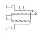
本実施例においては、前述したスリーブ内寸変化量とスリーブ圧入寸法との相関関係の解析に用いる第1および第2の試料(解析モデル)として、図3においてt1で示される圧入時保持部肉厚が許容最大値である0.60〔mm〕とされた第1の試料と、圧入時保持部肉厚t1が許容最小値である0.36〔mm〕とされた第2の試料とを想定する。 In the present embodiment, as the first and second sample used for the analysis of correlation between the aforementioned sleeve inside dimension variation and the sleeve press-fit dimension (analysis model), press-fitted holding unit represented by t 1 in FIG. 3 second sample thickness is first a sample which is the allowable the maximum value 0.60 mm and press-fitted holding section thickness t 1 is the allowable minimum value and 0.36 mm. Assuming that
ここで、本実施例においては、圧入時保持部肉厚t1と、図3においてt2で示される圧入時スリーブ肉厚との和であるレセプタクル肉厚t1+t2の規格寸法が、少なくとも0.836〔mm〕以上0.849〔mm〕以下の範囲内であることが前提とされている。また、本実施例においては、圧入時保持部肉厚t1が0.60〔mm〕よりも大きくなると、スリーブ3の製造が困難でスリーブ3の強度が保証できない旨の解析結果が出されていることが前提とされている。さらに、本実施例においては、圧入時保持部肉厚t1が0.36〔mm〕よりも小さくなると、スリーブ保持部5の製造が困難でスリーブ保持部5の強度が保証できない旨の解析結果が出されていることが前提とされている。
Here, in this embodiment, the standard dimension of the receptacle thickness t 1 + t 2 , which is the sum of the holding portion thickness t 1 during press-fitting and the sleeve thickness during press-fitting indicated by t 2 in FIG. 3, is at least It is assumed that it is within the range of 0.836 [mm] or more and 0.849 [mm] or less. Further, in this embodiment, when the press-fitting holding portion thickness t 1 is larger than 0.60 [mm], an analysis result is obtained that the
本実施例においては、このような前提の下で、前述のように、第1および第2の試料が想定されている。 In the present embodiment, the first and second samples are assumed as described above under such a premise.
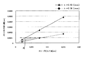
そして、本実施例においては、第1の試料に対して、スリーブ圧入寸法の値に対応したスリーブ内寸変化量の値を算出してプロットすることによって、図4において実線のグラフで示されるような相関関係の解析結果を取得する。 In this embodiment, the value of the in-sleeve dimensional change corresponding to the value of the sleeve press-fitting dimension is calculated and plotted for the first sample, as shown by the solid line graph in FIG. The analysis result of the correct correlation.
また、本実施例においては、第2の試料に対して、スリーブ圧入寸法の値に対応したスリーブ内寸変化量の値を算出してプロットすることによって、図4において破線のグラフで示されるような相関関係の解析結果を取得する。 Further, in this embodiment, by calculating and plotting the value of the in-sleeve dimension change amount corresponding to the value of the sleeve press-fitting dimension for the second sample, as shown by the broken line graph in FIG. The analysis result of the correct correlation.
さらに、本実施例においては、スリーブ3の内径公差に基づいて設定されているスリーブ内寸変化量の許容最大値を、図4において一点鎖線のグラフで示されるように、相関関係の解析結果に合成する。なお、図4におけるスリーブ内寸変化量の許容最大値は0.1〔μm〕となっているが、これは、スリーブ3の内径公差が±0.5〔μm〕であることに基づいて設定されたものである。
Furthermore, in this embodiment, the allowable maximum value of the change in the in-sleeve dimension set based on the inner diameter tolerance of the
そして、本実施例においては、このようにして得られた図4のグラフに基づいて、圧入時保持部肉厚t1が許容最小値(0.36〔mm〕)以上かつ許容最大値(0.60〔mm〕)以下となり、かつ、スリーブ内寸変化量が許容最大値(0.1〔μm〕)以下となるようなスリーブ圧入寸法の最適範囲を算出する。 In the present embodiment, on the basis of the graph of FIG. 4 obtained in this way, the press-fitting holding portion thickness t 1 is equal to or larger than the allowable minimum value (0.36 [mm]) and the allowable maximum value (0 .. [60 mm]) or less, and an optimum range of the sleeve press-fit dimension is calculated so that the amount of change in the sleeve dimension is less than the allowable maximum value (0.1 [μm]).
図4においては、前述した実線、破線および一点鎖線のグラフで囲まれる範囲、すなわち、図4においてハッチングが施された範囲Rが、スリーブ圧入寸法の最適範囲とされている。 In FIG. 4, the range surrounded by the graphs of the solid line, the broken line, and the alternate long and short dash line, that is, the hatched range R in FIG. 4, is the optimum range of the sleeve press-fitting dimension.
そして、このようにして算出された最適範囲Rの中から、所望のスリーブ圧入寸法を選択し、選択されたスリーブ圧入寸法を、光レセプタクル1の製造に用いるスリーブ圧入寸法として設定する。
Then, a desired sleeve press-fitting dimension is selected from the optimum range R calculated in this way, and the selected sleeve press-fitting dimension is set as a sleeve press-fitting dimension used for manufacturing the
ここで、例えば、圧入時保持部肉厚t1を0.5〔mm〕として設計したい場合には、図5において二点鎖線のグラフで示されるように、図4のグラフ上に、圧入時保持部肉厚t1を0.5〔mm〕とした場合におけるスリーブ圧入寸法とスリーブ内寸変化量との相関関係の解析結果を表示すればよい。そして、この表示された解析結果のグラフにおける最適範囲R内の一点に対応するスリーブ圧入寸法を選択し、選択されたスリーブ圧入寸法を光レセプタクル1の製造に用いるスリーブ圧入寸法として設定するようにすればよい。
Here, for example, when it is desired to design the holding portion thickness t 1 during press-fitting to be 0.5 [mm], as shown by a two-dot chain line graph in FIG. What is necessary is just to display the analysis result of the correlation between the sleeve press-fitting dimension and the in-sleeve dimension variation when the holding part thickness t 1 is 0.5 [mm]. Then, the sleeve press-fitting dimension corresponding to one point in the optimum range R in the graph of the displayed analysis result is selected, and the selected sleeve press-fitting dimension is set as the sleeve press-fitting dimension used for manufacturing the
(ウイグル特性評価)
次に、このようにしてスリーブ圧入寸法が設定されて製造された本実施例の光レセプタクル1に対するウイグル特性試験の試験結果について説明する。
(Uyghur characteristic evaluation)
Next, the test results of the wiggle characteristic test for the
なお、本ウイグル特性試験においては、光素子取付部8に光素子としての半導体レーザを取り付けるとともに、スリーブ保持部5内に圧入保持されたスリーブ3に、光ファイバ10の端部が保持されたフェルール11を挿入した状態の光レセプタクル1を用意した。
In this Uyghur characteristic test, a semiconductor laser as an optical element is attached to the optical
ただし、光レセプタクル1は、フェルール11の長手方向すなわち光ファイバ10の端部の光軸方向が水平となるように横向きに配置した。
However, the
そして、このようにして用意された実験系において、フェルール11に対して鉛直下方に荷重〔N〕を作用させ、半導体レーザと光ファイバ10との光結合効率の荷重に対する特性を調べた。
In the experimental system thus prepared, a load [N] was applied vertically downward to the
なお、本実施例の光レセプタクル1に対する比較例として、スリーブを有しない光レセプタクル(従来品)についても、本実施例の光レセプタクル1と同様に、光結合効率の荷重に対する特性を調べた。
As a comparative example for the
この結果、図6に示すような試験結果が得られた。 As a result, a test result as shown in FIG. 6 was obtained.
図6に示すように、本実施例における光レセプタクル1の方が、従来品に比べて荷重の増加に対する光結合効率〔dB〕の変化量が少ないことが分かる。これは、スリーブ3によって光レセプタクル1の剛性が高められていることによるものと推測される。
As shown in FIG. 6, it can be seen that the
(スリーブ抜去力評価)
次に、本実施例の光レセプタクル1に対する抜去力試験の試験結果について説明する。
(Sleeve removal force evaluation)
Next, the test results of the removal force test for the
本抜去力試験においては、スリーブ圧入寸法が3〔μm〕とされた光レセプタクル1について、スリーブ保持部5からスリーブ3を抜き去るのに要する抜去力を調べた。
In this removal force test, the removal force required to remove the
この結果、本実施例の光レセプタクル1については、スリーブ3の抜去力が16.0〔N〕であることが確認された。
As a result, for the
ここで、スリーブ3が安定的に保持されているといえる場合における抜去力は、3.0〔N〕以上とされている。このことを考慮すれば、本実施例においては、スリーブ3が十分安定的にスリーブ保持部5に保持されているということができる。
Here, when it can be said that the
以上述べたように、本発明によれば、スリーブ3をスリーブ保持部5内に圧入によって保持させることによって、接着を要することなく光レセプタクル1の剛性を向上させることができるので、良好なウイグル特性を低コストで実現することができるとともに、量産性を向上させることができる。
As described above, according to the present invention, the rigidity of the
なお、本発明は、前述した実施の形態に限定されるものではなく、必要に応じて種々の変更が可能である。 In addition, this invention is not limited to embodiment mentioned above, A various change is possible as needed.
例えば、本発明は、スリーブ3を光レセプタクル本体2よりも弾性率が高い材料によって形成するのであれば、スリーブ3を前述したセラミック材料以外の材料によって形成、光レセプタクル本体2を前述した樹脂材料以外の材料によって形成するようにしてもよい。
For example, in the present invention, if the
また、前述した実施形態における光レセプタクル本体2は、レンズ部7を有するものであったが、本発明は、レンズ以外の光学系(例えば、ファイバスタブ)を搭載した光レセプタクルにも適用可能なものである。
In addition, the
さらに、図7に示すように、レンズ部7の光学面7bとスリーブ3との間に挟まれた空間内に、ガラス(BK7等)や屈折率整合フィルム等の反射防止用光学部材17を配置するようにしてもよい。なお、屈折率整合フィルムとしては、例えば、FitWell(株式会社巴川製紙所製)を用いることができる。
Further, as shown in FIG. 7, an antireflection
また、図7においては、光学面7bとスリーブ3との間に配置された反射防止用光学部材17の外径が、スリーブ3の内径よりも大きく形成されているので、反射防止用光学部材17を接着を要することなく配置することができる。
In FIG. 7, since the outer diameter of the antireflection
なお、このような図7に示す光レセプタクル1においては、スリーブ3内への光ファイバ10の端部およびフェルール11の挿入状態において、フェルール11の端面が、反射防止用光学部材17の表面に当接するようになっている。
In the
次に、このような反射防止用光学部材17の一例として、屈折率1.50のBK7(ガラス)が配置された光レセプタクル1に対する使用波長を1550〔nm〕とした光結合効率のシミュレーション結果を以下の表1に示す。また、表1に対する比較例として、反射防止用光学部材17が配置されていない光レセプタクル1に対する使用波長を1550〔nm〕とした光結合効率のシミュレーション結果を以下の表2に示す。
Next, as an example of such an antireflection
さらに、反射防止用光学部材17の他の一例として、屈折率1.46のFitWell(屈折率整合フィルム)が配置された光レセプタクル1に対する使用波長を1310〔nm〕とした光結合効率のシミュレーション結果を以下の表3に示す。また、表3に対する比較例として、反射防止用光学部材17が配置されていない光レセプタクル1に対する使用波長を1310〔nm〕とした光結合効率のシミュレーション結果を以下の表4に示す。
Furthermore, as another example of the
なお、これらのシミュレーション結果は、フレネル反射を基に計算した。 These simulation results were calculated based on Fresnel reflection.

表1〜表4の結果から分かるように、光結合効率を向上させたい場合には、図7に示したように反射防止用光学部材17(特に、屈折率整合フィルム)を配置することが望ましい。 As can be seen from the results of Tables 1 to 4, when it is desired to improve the optical coupling efficiency, it is desirable to dispose an antireflection optical member 17 (particularly, a refractive index matching film) as shown in FIG. .
1 光レセプタクル
2 光レセプタクル本体
3 スリーブ
5 スリーブ保持部
DESCRIPTION OF
Claims (8)
このスリーブをその外周面を介して保持する筒状のスリーブ保持部が形成された光レセプタクル本体と
を備え、
前記スリーブは、前記光レセプタクル本体よりも弾性率が高い材料によって形成されているとともに、前記スリーブ保持部内に圧入によって保持されていること
を特徴とする光レセプタクル。 A cylindrical sleeve into which a ferrule that holds the end of the optical fiber is inserted;
An optical receptacle body formed with a cylindrical sleeve holding portion for holding the sleeve via its outer peripheral surface,
The optical receptacle is characterized in that the sleeve is made of a material having a higher elastic modulus than the optical receptacle body, and is held by press-fitting in the sleeve holding portion.
前記スリーブが前記スリーブ保持部内に圧入されていないスリーブ非圧入状態における前記スリーブの中心から前記スリーブの外周面までの径方向の寸法と、前記スリーブ非圧入状態における前記スリーブ保持部の中心から前記スリーブ保持部の内周面までの径方向の寸法との差として定義されるスリーブ圧入寸法は、
光レセプタクル本体の第1の試料であって、その圧入時保持部肉厚が、前記規格寸法および前記スリーブの製造性の観点に基づいて設定された所定の許容最大値をとるような第1の試料と、光レセプタクル本体の第2の試料であって、その圧入時保持部肉厚が、前記規格寸法および前記スリーブ保持部の製造性の観点に基づいて設定された所定の許容最小値をとるような第2の試料との2つの試料を想定し、
これら2つの試料のそれぞれについて、前記スリーブ非圧入状態における前記スリーブの中心から前記スリーブの内周面までの径方向の寸法に対する前記スリーブ圧入状態における前記スリーブの中心から前記スリーブの内周面までの径方向の寸法の変化量であるスリーブ内寸変化量と、スリーブ圧入寸法との相関関係の解析を行い、
これら2つの試料についての解析の結果と、前記スリーブ内寸変化量についての設定された所定の許容最大値とに基づいて、前記圧入時保持部肉厚が前記許容最小値以上かつ前記許容最大値以下となり、さらに、前記スリーブ内寸変化量が前記許容最大値以下となるような前記スリーブ圧入寸法の最適範囲を算出し、
算出された前記最適範囲の中から前記スリーブ圧入寸法を選択すること
によって設定されていることを特徴とする請求項1に記載の光レセプタクル。 The sleeve thickness at the time of press-fitting, which is a radial dimension from the inner peripheral surface of the sleeve to the outer peripheral surface of the sleeve in a sleeve press-fitted state in which the sleeve is press-fitted into the sleeve holding portion, and the sleeve holding in the sleeve press-fitted state The sum of the press-fit holding part thickness that is the radial dimension from the inner peripheral surface of the part to the outer peripheral surface of the sleeve holding part is formed so as to satisfy a predetermined standard dimension,
A radial dimension from the center of the sleeve to the outer peripheral surface of the sleeve when the sleeve is not press-fitted into the sleeve holding portion and the sleeve from the center of the sleeve holding portion when the sleeve is not press-fitted The sleeve press-fit dimension, defined as the difference from the radial dimension to the inner peripheral surface of the holding part,
A first sample of the optical receptacle body, wherein the thickness of the holding portion at the time of press-fitting takes a predetermined allowable maximum value set on the basis of the standard dimensions and the manufacturability of the sleeve. The sample and the second sample of the optical receptacle main body, and the thickness of the holding portion at the time of press-fitting takes a predetermined allowable minimum value set based on the standard dimension and the viewpoint of manufacturability of the sleeve holding portion. Assuming two samples with such a second sample,
For each of these two samples, from the center of the sleeve to the inner peripheral surface of the sleeve in the sleeve press-fitted state with respect to the radial dimension from the center of the sleeve to the inner peripheral surface of the sleeve in the sleeve non-press-fitted state. Analyze the correlation between the sleeve internal dimension change, which is the radial dimension change, and the sleeve press-fit dimension,
Based on the results of the analysis of these two samples and the predetermined maximum allowable value set for the amount of change in the sleeve dimension, the thickness of the holding portion during press-fitting is equal to or greater than the allowable minimum value and the allowable maximum value. And further, an optimum range of the sleeve press-fit dimension is calculated such that the sleeve internal dimension change amount is not more than the allowable maximum value,
2. The optical receptacle according to claim 1, wherein the optical receptacle is set by selecting the sleeve press-fitting dimension from the calculated optimum range.
前記スリーブが、セラミック材料によって形成されていること
を特徴とする請求項1または2に記載の光レセプタクル。 The optical receptacle body is formed of a resin material,
The optical receptacle according to claim 1, wherein the sleeve is made of a ceramic material.
を特徴とする請求項1〜3のいずれか1項に記載の光レセプタクル。 The optical receptacle according to any one of claims 1 to 3, wherein the optical receptacle body includes a lens on an optical path of light transmitted by the optical fiber.
このスリーブをその外周面を介して保持する筒状のスリーブ保持部を有する光レセプタクル本体と
を有する光レセプタクルの製造方法であって、
前記スリーブを、前記光レセプタクル本体よりも弾性率が高い材料によって形成し、
前記スリーブを、前記スリーブ保持部内に圧入によって保持させること
を特徴とする光レセプタクルの製造方法。 A cylindrical sleeve into which a ferrule that holds the end of the optical fiber is inserted;
An optical receptacle manufacturing method comprising: an optical receptacle main body having a cylindrical sleeve holding portion for holding the sleeve via an outer peripheral surface thereof;
The sleeve is formed of a material having a higher elastic modulus than the optical receptacle body,
A method of manufacturing an optical receptacle, wherein the sleeve is held by press fitting into the sleeve holding portion.
前記スリーブが前記スリーブ保持部内に圧入されていないスリーブ非圧入状態における前記スリーブの中心から前記スリーブの外周面までの径方向の寸法と、前記スリーブ非圧入状態における前記スリーブ保持部の中心から前記スリーブ保持部の内周面までの径方向の寸法との差として定義されるスリーブ圧入寸法を設定する際に、
光レセプタクル本体の第1の試料であって、その圧入時保持部肉厚が、前記規格寸法および前記スリーブの製造性の観点に基づいて設定された所定の許容最大値をとるような第1の試料と、光レセプタクル本体の第2の試料であって、その圧入時保持部肉厚が、前記規格寸法および前記スリーブ保持部の製造性の観点に基づいて設定された所定の許容最小値をとるような第2の試料との2つの試料を想定し、
これら2つの試料のそれぞれについて、前記スリーブ非圧入状態における前記スリーブの中心から前記スリーブの内周面までの径方向の寸法に対する前記スリーブ圧入状態における前記スリーブの中心から前記スリーブの内周面までの径方向の寸法の変化量であるスリーブ内寸変化量と、スリーブ圧入寸法との相関関係の解析を行い、
これら2の試料についての解析の結果と、前記スリーブ内寸変化量についての設定された許容最大値とに基づいて、前記圧入時保持部肉厚が前記許容最小値以上かつ前記許容最大値以下となり、かつ、前記スリーブ内寸変化量が前記許容最大値以下となるような前記スリーブ圧入寸法の最適範囲を算出し、
算出された前記最適範囲の中から前記スリーブ圧入寸法を選択すること
によって前記スリーブ圧入寸法を設定すること
を特徴とする請求項5に記載の光レセプタクルの製造方法。 The sleeve thickness at the time of press-fitting, which is a radial dimension from the inner peripheral surface of the sleeve to the outer peripheral surface of the sleeve in a sleeve press-fitted state in which the sleeve is press-fitted into the sleeve holding portion, and the sleeve holding in the sleeve press-fitted state Forming the sum of the thickness of the holding portion during press-fitting, which is a radial dimension from the inner peripheral surface of the portion to the outer peripheral surface of the sleeve holding portion, so as to satisfy a predetermined standard dimension,
A radial dimension from the center of the sleeve to the outer peripheral surface of the sleeve when the sleeve is not press-fitted into the sleeve holding portion and the sleeve from the center of the sleeve holding portion when the sleeve is not press-fitted When setting the sleeve press-fit dimension, which is defined as the difference from the radial dimension to the inner peripheral surface of the holding part,
A first sample of the optical receptacle body, wherein the thickness of the holding portion at the time of press-fitting takes a predetermined allowable maximum value set on the basis of the standard dimensions and the manufacturability of the sleeve. The sample and the second sample of the optical receptacle main body, and the thickness of the holding portion at the time of press-fitting takes a predetermined allowable minimum value set based on the standard dimension and the viewpoint of manufacturability of the sleeve holding portion. Assuming two samples with such a second sample,
For each of these two samples, from the center of the sleeve to the inner peripheral surface of the sleeve in the sleeve press-fitted state with respect to the radial dimension from the center of the sleeve to the inner peripheral surface of the sleeve in the sleeve non-press-fitted state. Analyze the correlation between the sleeve internal dimension change, which is the radial dimension change, and the sleeve press-fit dimension,
Based on the results of the analysis of these two samples and the set allowable maximum value for the amount of change in the inner dimension of the sleeve, the thickness of the holding portion during press-fitting is not less than the allowable minimum value and not more than the allowable maximum value. And calculating an optimum range of the sleeve press-fit dimensions such that the sleeve internal dimension change amount is not more than the allowable maximum value,
6. The method of manufacturing an optical receptacle according to claim 5, wherein the sleeve press-fitting dimension is set by selecting the sleeve press-fitting dimension from the calculated optimum range.
前記スリーブを、セラミック材料によって形成すること
を特徴とする請求項5または6に記載の光レセプタクルの製造方法。 The optical receptacle body is formed of a resin material,
The method for manufacturing an optical receptacle according to claim 5, wherein the sleeve is made of a ceramic material.
を特徴とする請求項5〜7のいずれか1項に記載の光レセプタクルの製造方法。 The method for manufacturing an optical receptacle according to any one of claims 5 to 7, wherein when forming the optical receptacle body, a lens is formed on an optical path of light transmitted by the optical fiber.
Priority Applications (2)
| Application Number | Priority Date | Filing Date | Title |
|---|---|---|---|
| JP2008196081A JP5060419B2 (en) | 2008-07-30 | 2008-07-30 | Manufacturing method of optical receptacle |
| US12/460,645 US7891884B2 (en) | 2008-07-30 | 2009-07-22 | Optical receptacle and manufacturing method thereof |
Applications Claiming Priority (1)
| Application Number | Priority Date | Filing Date | Title |
|---|---|---|---|
| JP2008196081A JP5060419B2 (en) | 2008-07-30 | 2008-07-30 | Manufacturing method of optical receptacle |
Related Child Applications (1)
| Application Number | Title | Priority Date | Filing Date |
|---|---|---|---|
| JP2012153600A Division JP2012194583A (en) | 2012-07-09 | 2012-07-09 | Optical receptacle kit |
Publications (2)
| Publication Number | Publication Date |
|---|---|
| JP2010032866A true JP2010032866A (en) | 2010-02-12 |
| JP5060419B2 JP5060419B2 (en) | 2012-10-31 |
Family
ID=41608454
Family Applications (1)
| Application Number | Title | Priority Date | Filing Date |
|---|---|---|---|
| JP2008196081A Expired - Fee Related JP5060419B2 (en) | 2008-07-30 | 2008-07-30 | Manufacturing method of optical receptacle |
Country Status (2)
| Country | Link |
|---|---|
| US (1) | US7891884B2 (en) |
| JP (1) | JP5060419B2 (en) |
Cited By (2)
| Publication number | Priority date | Publication date | Assignee | Title |
|---|---|---|---|---|
| JP2011174988A (en) * | 2010-02-23 | 2011-09-08 | Yazaki Corp | Optical fiber module and method for producing the same |
| JP2012194583A (en) * | 2012-07-09 | 2012-10-11 | Enplas Corp | Optical receptacle kit |
Families Citing this family (3)
| Publication number | Priority date | Publication date | Assignee | Title |
|---|---|---|---|---|
| GB0911359D0 (en) | 2009-06-30 | 2009-08-12 | Fibreco Ltd | Expanded beam optical fibre connection |
| JP2011232496A (en) | 2010-04-27 | 2011-11-17 | Sumitomo Electric Ind Ltd | Optical connector module |
| JP5750997B2 (en) | 2010-05-17 | 2015-07-22 | 住友電気工業株式会社 | Optical connector module |
Citations (4)
| Publication number | Priority date | Publication date | Assignee | Title |
|---|---|---|---|---|
| JP2003241031A (en) * | 2002-02-15 | 2003-08-27 | Sumitomo Electric Ind Ltd | Optical module and optical transmitter receiver |
| JP2004287198A (en) * | 2003-03-24 | 2004-10-14 | Adamant Kogyo Co Ltd | Precision sleeve type receptacle |
| JP2005122086A (en) * | 2003-09-25 | 2005-05-12 | Kyocera Corp | Optical receptacle and optical module using it |
| JP2007041516A (en) * | 2005-06-30 | 2007-02-15 | Kyocera Corp | Receptacle and optical module equipped with the same |
Family Cites Families (6)
| Publication number | Priority date | Publication date | Assignee | Title |
|---|---|---|---|---|
| JP3087561B2 (en) * | 1993-12-28 | 2000-09-11 | 三菱電機株式会社 | Optical semiconductor module and manufacturing method thereof |
| US5684903A (en) * | 1994-06-30 | 1997-11-04 | Hamamatsu Photonics K.K. | Receptacle and method of manufacturing the same |
| JP4413417B2 (en) * | 2000-12-18 | 2010-02-10 | 古河電気工業株式会社 | Laser diode module |
| JP2003227968A (en) * | 2002-02-01 | 2003-08-15 | Sony Corp | Optical link device |
| JP2004354452A (en) * | 2003-05-27 | 2004-12-16 | Enplas Corp | Optical module, its manufacturing method, and holder for optical modules |
| JP2006184338A (en) | 2004-12-24 | 2006-07-13 | Kyocera Corp | Optical receptacle and optical module using same |
-
2008
- 2008-07-30 JP JP2008196081A patent/JP5060419B2/en not_active Expired - Fee Related
-
2009
- 2009-07-22 US US12/460,645 patent/US7891884B2/en active Active
Patent Citations (4)
| Publication number | Priority date | Publication date | Assignee | Title |
|---|---|---|---|---|
| JP2003241031A (en) * | 2002-02-15 | 2003-08-27 | Sumitomo Electric Ind Ltd | Optical module and optical transmitter receiver |
| JP2004287198A (en) * | 2003-03-24 | 2004-10-14 | Adamant Kogyo Co Ltd | Precision sleeve type receptacle |
| JP2005122086A (en) * | 2003-09-25 | 2005-05-12 | Kyocera Corp | Optical receptacle and optical module using it |
| JP2007041516A (en) * | 2005-06-30 | 2007-02-15 | Kyocera Corp | Receptacle and optical module equipped with the same |
Cited By (2)
| Publication number | Priority date | Publication date | Assignee | Title |
|---|---|---|---|---|
| JP2011174988A (en) * | 2010-02-23 | 2011-09-08 | Yazaki Corp | Optical fiber module and method for producing the same |
| JP2012194583A (en) * | 2012-07-09 | 2012-10-11 | Enplas Corp | Optical receptacle kit |
Also Published As
| Publication number | Publication date |
|---|---|
| US7891884B2 (en) | 2011-02-22 |
| US20100027944A1 (en) | 2010-02-04 |
| JP5060419B2 (en) | 2012-10-31 |
Similar Documents
| Publication | Publication Date | Title |
|---|---|---|
| JP5740800B1 (en) | Optical receptacle | |
| US9709750B1 (en) | 2-dimensional fiber array structure | |
| JP5060419B2 (en) | Manufacturing method of optical receptacle | |
| CN104508524A (en) | Fiber optic modules having a fiber tray, optical-to-optical fiber optic connectors, and methods thereof | |
| US9995892B2 (en) | Optical communication modules | |
| JP2002182073A (en) | Light source-optical fiber coupler | |
| KR101760156B1 (en) | Optical collimator and optical connector using same | |
| JP2018072499A (en) | Coupling lens and laser optical system | |
| JP5543293B2 (en) | Small-diameter bending optical connector | |
| JP2008032993A (en) | Optical fiber body and mode converter using the same | |
| JP2013104884A (en) | Optical path conversion member and optical module | |
| JP2004126563A (en) | Lens integrated-type optical fiber and manufacturing method therefor | |
| JP2010231130A (en) | Optical module | |
| JP2006003661A (en) | Method of manufacturing optical connector and ferrule | |
| JP2012194583A (en) | Optical receptacle kit | |
| JP2012237819A (en) | Holder for an optical module | |
| JP2007178980A (en) | Ferrule holder and eccentricity measuring apparatus using the same | |
| JP2004302222A (en) | Optical fiber collimator and manufacturing method therefor | |
| JP2005024617A (en) | Optical transmitter | |
| JP2004151373A (en) | On-vehicle optical connector | |
| JP5697347B2 (en) | Optical fiber module and manufacturing method thereof | |
| JP5095575B2 (en) | Optical coupling structure between optical element and optical fiber | |
| WO2020039636A1 (en) | Optical connector unit and optical connection structure | |
| WO2016175126A1 (en) | Optical transmission module | |
| JP2019003169A (en) | Optical connector module |
Legal Events
| Date | Code | Title | Description |
|---|---|---|---|
| A621 | Written request for application examination |
Free format text: JAPANESE INTERMEDIATE CODE: A621 Effective date: 20110620 |
|
| A131 | Notification of reasons for refusal |
Free format text: JAPANESE INTERMEDIATE CODE: A131 Effective date: 20120529 |
|
| A977 | Report on retrieval |
Free format text: JAPANESE INTERMEDIATE CODE: A971007 Effective date: 20120531 |
|
| A521 | Request for written amendment filed |
Free format text: JAPANESE INTERMEDIATE CODE: A523 Effective date: 20120709 |
|
| TRDD | Decision of grant or rejection written | ||
| A01 | Written decision to grant a patent or to grant a registration (utility model) |
Free format text: JAPANESE INTERMEDIATE CODE: A01 Effective date: 20120731 |
|
| A01 | Written decision to grant a patent or to grant a registration (utility model) |
Free format text: JAPANESE INTERMEDIATE CODE: A01 |
|
| A61 | First payment of annual fees (during grant procedure) |
Free format text: JAPANESE INTERMEDIATE CODE: A61 Effective date: 20120803 |
|
| FPAY | Renewal fee payment (event date is renewal date of database) |
Free format text: PAYMENT UNTIL: 20150810 Year of fee payment: 3 |
|
| R150 | Certificate of patent or registration of utility model |
Ref document number: 5060419 Country of ref document: JP Free format text: JAPANESE INTERMEDIATE CODE: R150 Free format text: JAPANESE INTERMEDIATE CODE: R150 |
|
| R250 | Receipt of annual fees |
Free format text: JAPANESE INTERMEDIATE CODE: R250 |
|
| R250 | Receipt of annual fees |
Free format text: JAPANESE INTERMEDIATE CODE: R250 |
|
| R250 | Receipt of annual fees |
Free format text: JAPANESE INTERMEDIATE CODE: R250 |
|
| R250 | Receipt of annual fees |
Free format text: JAPANESE INTERMEDIATE CODE: R250 |
|
| R250 | Receipt of annual fees |
Free format text: JAPANESE INTERMEDIATE CODE: R250 |
|
| R250 | Receipt of annual fees |
Free format text: JAPANESE INTERMEDIATE CODE: R250 |
|
| LAPS | Cancellation because of no payment of annual fees |