JP2010032258A - Apparatus and method for recognizing position of work for depalletizing - Google Patents
Apparatus and method for recognizing position of work for depalletizing Download PDFInfo
- Publication number
- JP2010032258A JP2010032258A JP2008192583A JP2008192583A JP2010032258A JP 2010032258 A JP2010032258 A JP 2010032258A JP 2008192583 A JP2008192583 A JP 2008192583A JP 2008192583 A JP2008192583 A JP 2008192583A JP 2010032258 A JP2010032258 A JP 2010032258A
- Authority
- JP
- Japan
- Prior art keywords
- image
- workpiece
- work
- pattern
- contour data
- Prior art date
- Legal status (The legal status is an assumption and is not a legal conclusion. Google has not performed a legal analysis and makes no representation as to the accuracy of the status listed.)
- Granted
Links
Images


Abstract
Description
本発明は、デパレタイズ用のワーク位置認識装置および方法に関する。 The present invention relates to a workpiece position recognition apparatus and method for depalletizing.
パレット上に積まれた段ボール箱などのワークを1つづつ荷降ろしすることを「デパレタイズ」という。デパレタイズ用の産業用ロボット(デパレタイズロボット)を用いてデパレタイズする場合、パレット上面を撮影した画像から、最上段に位置するワークの位置と姿勢を正確に検出する必要がある。
そのため、ワーク位置を認識する手段が種々提案されている(例えば、特許文献1〜3)。
The unloading of works such as cardboard boxes loaded on a pallet one by one is called “depalletizing”. In the case of depalletizing using a depalletizing industrial robot (depalletizing robot), it is necessary to accurately detect the position and posture of the workpiece located at the uppermost stage from an image obtained by photographing the top surface of the pallet.
For this reason, various means for recognizing the workpiece position have been proposed (for example,
特許文献1は、物品(ワーク)位置検出を行い、自動デパレタイズを可能とすることを目的とする。
そのため、特許文献1では、図4に示すように、ワークの高さを検出するエリアセンサと、このエリアセンサにより検出された高さデータに基づいて最上段のワークFの側面に対して4方から照明する照明装置52と、パレットPの上方よりワークFを撮影するCCDカメラ54と、CCDカメラ54により撮影された撮影データより、最上段のワークFの上面(影の部分)を抽出し、最上段のワークFの輪郭を検出する画像処理装置とを備え、画像処理装置により検出された最上段のワークFの輪郭データにより、最上段のワークFの概略位置を判断し、ワークFの位置を認識するものである。
Therefore, in
特許文献2は、パレタイズされている直方体の箱体の中から、簡易に最上部に位置している箱体を特定することを目的とする。
そのため、特許文献2では、図5に示すように、パレタイズされている箱Bに斜め上方から照明し、それをステレオテレビカメラ装置56,56により撮影し、その撮影された画像から陰影のあるエッジを抽出し、それらを3次元計測して最上位のものを選択する。ついで、上方よりの照明に切り換えて、再度撮影して残りのエッジを特定した後マッチングを行い、箱の種別、姿勢および把持位置を決定するものである。
Therefore, in
特許文献3は、画像から目的とする物品の位置と姿勢を精密かつ確実に検出でき、かつFAなどに適用可能な高速処理ができることを目的とする。
そのため、特許文献3では、図6に示すように、複数の同一物品が同一平面上に並んだ画像63を撮影し、画像から物品の位置及び姿勢69を検出し、物品の形状データ64から画像上の物品の輪郭を示すテンプレート65を生成し、画像から物品の形状を強調した二値のエッジ画像66を作成し、テンプレートとエッジ画像のベクトル相関により物品候補データ67を作成し、エッジ画像からエッジを構成する線分データ68を作成し、物品候補データと線分データから線分探索により物品の正確な位置と姿勢69を決定するものである。
Patent Document 3 aims to accurately and reliably detect the position and orientation of a target article from an image, and to perform high-speed processing applicable to FA and the like.
Therefore, in Patent Document 3, as shown in FIG. 6, an
特許文献1の装置では、最上段の物品の側面に対して照明することにより、上方から撮影された最上段の物品の上面、エッジに濃い影が生じるため、明確な輪郭が検出される。この輪郭データよって最上段の物品の概略位置が判断され、物品の位置が認識される。
しかし、特許文献1では、輪郭データのみを用いてワーク位置を認識するため、段ボール箱などのワークでは誤検出が起きる可能性が高い。
In the apparatus of
However, in
特許文献2の手段では、斜め上方から照明された箱をステレオカメラにより撮影し、その撮影された画像からエッジを抽出し、3次元計測により最上位のものを選択する。その後、上方よりの照明に切り換えて、別のステレオカメラにより再度撮影し残りのエッジを特定する。統合された複数のエッジ情報から箱の種別、姿勢および把持位置を決定する。
しかし、特許文献2の手段では、照明およびステレオカメラが複数必要となるためシステムの規模が大きくなる。また、ステレオカメラから複数のエッジを求め統合する必要があるため、計算負荷が高くなる。
In the method of
However, since the means of
特許文献3の手段では、物品上面の輪郭データをテンプレートとしてベクトル相関と線分探索を用いるため、物品の位置と姿勢を精密に検出できる。
しかし、特許文献3の手段であっても、物品の形状や模様、画像の鮮明度などにより、物品の位置または姿勢を誤って検出することがあった。例えば、同一平面上に並んだ複数の同一物品(例えば段ボール)が、単一物品の輪郭に近似した模様や合わせ面を有する場合、位置または姿勢の誤検出が生じることがあった。
With the means of Patent Document 3, since the vector correlation and the line segment search are used using the contour data of the upper surface of the article as a template, the position and orientation of the article can be accurately detected.
However, even with the means of Patent Document 3, the position or posture of an article may be erroneously detected depending on the shape and pattern of the article, the sharpness of an image, and the like. For example, when a plurality of identical articles (for example, cardboard) arranged on the same plane have a pattern or a mating surface that approximates the outline of a single article, erroneous detection of position or orientation may occur.
本発明は上述した従来の問題点を解決するために創案されたものである。すなわち、本発明の目的は、ワーク上面の輪郭データに基づく誤検出を大幅に低減することができ、ワークの形状、模様及び画像の鮮明度の影響を低減して認識精度を高め、常に高い精度とワークの位置と姿勢を検出することができるデパレタイズ用のワーク位置認識装置および方法を提供することにある。 The present invention has been developed to solve the above-described conventional problems. That is, the object of the present invention is to greatly reduce the false detection based on the contour data of the workpiece upper surface, to reduce the influence of the workpiece shape, pattern and image sharpness, to improve the recognition accuracy, always high accuracy Another object is to provide a depalletizing work position recognition apparatus and method capable of detecting the position and orientation of a work.
本発明によれば、複数の同一ワークが同一平面上に並んだ画像を撮影する撮影装置と、撮影した画像を画像処理する画像処理装置とを備え、ワークの位置と姿勢を検出してロボット制御装置にその結果を出力するワーク位置認識装置であって、
該ワーク位置認識装置は、前記画像から輪郭データを取得し、該輪郭データから各ワークの位置及び姿勢を検出し、前記画像中のワーク部分の画像をマスタ画像パターンとして登録し、該マスタ画像パターンと各ワーク部分の画像とのパターンマッチングを行い、すべてのワーク部分に対しパターンマッチングが成功した場合に、各ワークの位置及び姿勢を出力する、ことを特徴とするワーク位置認識装置が提供される。
According to the present invention, it is provided with a photographing device that photographs an image in which a plurality of identical workpieces are arranged on the same plane, and an image processing device that performs image processing on the photographed image, and controls the robot by detecting the position and orientation of the workpiece. A workpiece position recognition device that outputs the result to a device,
The workpiece position recognition device acquires contour data from the image, detects the position and orientation of each workpiece from the contour data, registers an image of a workpiece portion in the image as a master image pattern, and the master image pattern A workpiece position recognition device is provided, which performs pattern matching between the image of each workpiece part and outputs the position and orientation of each workpiece when pattern matching is successful for all workpiece parts. .
また本発明によれば、撮影装置により、複数の同一ワークが同一平面上に並んだ画像を撮影し、
画像処理装置により、前記画像から輪郭データを取得し、該輪郭データから各ワークの位置及び姿勢を検出し、前記画像中のワーク部分の画像をマスタ画像パターンとして登録し、該マスタ画像パターンと各ワーク部分の画像とのパターンマッチングを行い、すべてのワーク部分に対しパターンマッチングが成功した場合に、各ワークの位置及び姿勢を出力する、ことを特徴とするワーク位置認識方法が提供される。
Further, according to the present invention, the image capturing device captures an image in which a plurality of identical works are arranged on the same plane,
The image processing device acquires contour data from the image, detects the position and orientation of each workpiece from the contour data, registers the image of the workpiece portion in the image as a master image pattern, There is provided a work position recognition method characterized in that pattern matching with an image of a work part is performed, and when the pattern matching is successful for all work parts, the position and orientation of each work are output.
本発明の好ましい実施形態によれば、マスタ画像パターンとして、検出したワークと輪郭データとの一致度の最も高いワーク画像を最初に登録し、
すべてのワーク部分に対しパターンマッチングが成功しない場合に、前記一致度が順次高いワーク部分の画像をマスタ画像パターンに登録する。
According to a preferred embodiment of the present invention, as a master image pattern, a work image having the highest degree of coincidence between the detected work and the contour data is first registered,
If pattern matching is not successful for all work parts, the images of the work parts having successively higher matching degrees are registered in the master image pattern.
前記検出したワークと輪郭データとの一致度として、ベクトル相関値を用いる、ことが好ましい。 It is preferable to use a vector correlation value as the degree of coincidence between the detected workpiece and the contour data.
上述した本発明の装置および方法によれば、画像中のワーク部分の画像をマスタ画像パターンとして登録し、該マスタ画像パターンと各ワーク部分の画像とのパターンマッチングを行い、すべてのワークの画像に対しパターンマッチングが成功した場合に、各ワークの位置及び姿勢を出力するので、ワーク上面の輪郭データに基づく誤検出を大幅に低減することができ、ワークの形状、模様及び画像の鮮明度の影響を低減して認識精度を高め、常に高い精度とワークの位置と姿勢を検出することができる。 According to the apparatus and method of the present invention described above, an image of a work part in an image is registered as a master image pattern, pattern matching between the master image pattern and the image of each work part is performed, and images of all work parts are registered. When pattern matching is successful, the position and orientation of each workpiece are output, so that false detection based on the contour data on the workpiece upper surface can be greatly reduced, and the effect of the workpiece shape, pattern, and image clarity. The recognition accuracy can be improved by reducing the above, and the position and posture of the workpiece can always be detected with high accuracy.
本発明の装置および方法は、エッジ検出に基づくテンプレートマッチングと、ワーク部分の画像を用いたパターンマッチングの組み合わせであり、それぞれ簡単な認識処理であるため、計算負荷が小さい。
また、マスタ画像パターンは計測の度に取得するため、ワーク毎に画像データを保持しておく必要がなく、ワークが変更されても再度教示する必要がない。
また、本発明は複数のセンサを必要としないため、従来技術に比べて計測部(撮影装置)を簡易にできる。
The apparatus and method of the present invention are a combination of template matching based on edge detection and pattern matching using an image of a work part, and each is a simple recognition process, so that the calculation load is small.
Further, since the master image pattern is acquired every measurement, it is not necessary to store image data for each work, and there is no need to teach again even if the work is changed.
In addition, since the present invention does not require a plurality of sensors, the measurement unit (imaging device) can be simplified as compared with the prior art.
従って、認識精度が向上し、誤検出が起きにくくなり、計算負荷、メモリ負荷が小さくでき、計測部(撮影装置)が単一ですむため、システム規模を小さくできる。 Accordingly, recognition accuracy is improved, erroneous detection is less likely to occur, calculation load and memory load can be reduced, and a single measurement unit (imaging device) is required, so that the system scale can be reduced.
以下、本発明の好ましい実施例を図面を参照して説明する。なお、各図において共通する部分には同一の符号を付し、重複した説明を省略する。 Hereinafter, preferred embodiments of the present invention will be described with reference to the drawings. In addition, the same code | symbol is attached | subjected to the common part in each figure, and the overlapping description is abbreviate | omitted.
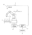
図1は、本発明のワーク位置認識装置を備えたデパレタイズ装置の全体構成図である。
この図において、ワーク1は、例えば同一の段ボール箱であり、パレット2の上に積層されている。パレット2は、デパレタイズ用の産業用ロボット(デパレタイズロボット)10に隣接する所定のピックステーション(この図では2箇所)に設置される。
FIG. 1 is an overall configuration diagram of a depalletizing apparatus provided with a workpiece position recognition apparatus of the present invention.
In this figure, a
この図に示すように、本発明のワーク位置認識装置は、複数の同一ワーク1が同一平面上に並んだ画像3を撮影する撮影装置12と、撮影した画像3を画像処理する画像処理装置14とを備える。
As shown in this figure, the workpiece position recognition apparatus of the present invention includes an
この例では本発明のワーク位置認識装置は、パレット上のワークのうち、最上段のワークのみを対象とし、画像3から最上段のワーク1の位置及び姿勢を検出するものである。
In this example, the workpiece position recognition apparatus of the present invention detects only the uppermost workpiece among the workpieces on the pallet, and detects the position and orientation of the
撮影装置12は、例えばデジタル画像が取得できるデジタルスチールカメラ又はデジタルビデオカメラである。なお、これらのカメラは、少なくとも最上段のワークすべてを撮影でき、かつ各ワークを識別できる分解能を有する。
なお本発明は、最上段のワークをその他のワークと識別する手段について特に限定しない。例えば、撮影装置12として、ワークまでの距離を検出できるように、一定の間隔を隔てたステレオカメラまたは三次元レーザー測定器を用いてもよい。
The photographing
Note that the present invention does not particularly limit the means for distinguishing the uppermost workpiece from other workpieces. For example, as the
画像処理装置14は、この例では画像処理PC(コンピュータ)であり、ロボット制御装置15および倉庫管理PC16とLANで接続されている。倉庫管理PC16には、ワークの形状データが予め入力されている。
In this example, the
画像処理装置14は、撮影装置12で撮影した画像から、ワークまでの距離等を基準にして最上段のワーク以外の画像を消去する。次いで、画像処理装置14により、本発明のワーク位置認識方法を実行し、ワークの位置と姿勢を検出して、ロボット制御装置15にその結果を出力する。
ロボット制御装置15は、画像処理装置14によるワークの位置と姿勢に基づき、デパレタイズロボット10を制御し、パレット上に積まれたワークを1つづつ荷降ろしするデパレタイズ作業を実行する。
The
The
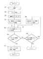
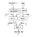
図2は、本発明によるワーク位置認識方法を示すフロー図である。また、図3は、本発明のワーク位置認識方法の説明図である。 FIG. 2 is a flowchart showing a work position recognition method according to the present invention. FIG. 3 is an explanatory diagram of the work position recognition method of the present invention.
図2に示すように、本発明のワーク位置認識方法は、S1〜S9の各ステップからなる。
ステップS1では、撮影装置12により、ピックステーションにパレタイズされた単一種かつ複数のワーク1を上部より撮影し、ワーク上部の画像3aを取得する。
As shown in FIG. 2, the work position recognition method of the present invention includes steps S1 to S9.
In step S1, a single type and a plurality of
図3(A)は、画像3aの例であり、この例では、10個のワーク1が画像3aに含まれている。以下、10個のワーク1をそれぞれワーク1a〜1jと呼ぶ。各ワーク1(1a〜1j)の輪郭は長方形であり、ワーク上面には、a,b,c,dの4つのマーク又は模様がそれぞれ存在する。
FIG. 3A is an example of the
ステップS2では、ワーク上部の画像3aに対してエッジ抽出を行う。
ステップS3では、ワークの寸法情報から得られるワークの輪郭(テンプレート5)とステップS2で抽出したエッジ情報とをマッチング(テンプレートマッチング)させ、各ワークの位置及び姿勢を検出する。
ワークの寸法情報(テンプレート)は、好ましくは倉庫管理PC16から取得する。なお、このテンプレート5は、倉庫管理PC16に記録されたワークの形状データから画像上のワークの輪郭(テンプレート5)を生成するのがよい。
In step S2, edge extraction is performed on the
In step S3, the workpiece outline (template 5) obtained from the workpiece dimension information and the edge information extracted in step S2 are matched (template matching) to detect the position and orientation of each workpiece.
The workpiece dimension information (template) is preferably obtained from the
図3(B)は、ステップS3で輪郭のマッチング(テンプレートマッチング)を行った後の、画像3bである。この図において、5はテンプレートであり、ワーク1aの検出に失敗し、ワーク1b,1cは誤検出し、その他のワーク1d〜1jの検出は成功している状態を示している。
FIG. 3B shows an
ステップS3では、さらに検出した各ワーク1b〜1jとテンプレート5との間で、ベクトル相関を実施し、それぞれのベクトル相関値を求め、ベクトル相関値の大きい順に、各ワーク1b〜1jを第1候補、第2候補、と順位を設定する。
ベクトル相関は、二値画像(エッジ画像)中から、テンプレートと類似した幾何形状の位置を探索する方法であり、例えば特許文献3に開示されている。またベクトル相関値は、その値が大きいほど、テンプレート5と画像3b上の図が一致していることを意味する。
In step S3, vector correlation is further performed between the detected
Vector correlation is a method for searching for a position of a geometric shape similar to a template from a binary image (edge image), and is disclosed in, for example, Patent Document 3. Further, the larger the value of the vector correlation value means that the
ステップS4では、最も輪郭一致度の高いワーク、すなわちベクトル相関値が最も大きい第1候補のワーク(例えばワーク1d)を選び、その輪郭の内側の画像をマスタ画像パターン6として切り出し登録する。
In step S4, a work having the highest contour matching degree, that is, a first candidate work (for example,
ステップS5では、他のワークに対して、画像中のワーク部分(輪郭の内側)の画像を抽出し、マスタ画像パターン6と各ワーク部分の画像とのパターンマッチングを順次行う。このパターンマッチングでは、ワーク上面のa,b,c,dのマーク又は模様に対してもパターンマッチングする。
そして、検出した各ワークの位置及び姿勢にうち、誤った候補がないか検証する。
In step S5, an image of the work part (inside the contour) in the image is extracted from another work, and pattern matching between the
Then, it is verified whether there is an erroneous candidate in the detected position and posture of each workpiece.
ステップS6では、搬送するべきワークの個数(この例では10個)の照合が成功したかを調べる。すべての照合に成功していればステップS7へ、失敗したワークがあればステップS8へ進む。
このステップS6で指定個数(この例では10個)の照合が成功しなかったのは、不正なマスタ画像パターンが登録されているためである。
図3(B)の例では、ワーク1aの検出に失敗し、ワーク1b,1cは誤検出しているので、失敗したワークがありステップS8へ進む。
In step S6, it is checked whether the number of workpieces to be transported (in this example, 10) has been successfully verified. If all collations are successful, the process proceeds to step S7, and if there is a failed work, the process proceeds to step S8.
The reason why the specified number (10 in this example) of collation has not succeeded in step S6 is that an illegal master image pattern has been registered.
In the example of FIG. 3B, detection of the
搬送するべきワークの個数(この例では10個)の照合が成功した場合(YES)、ステップS7でロボット制御装置15に位置情報(位置と姿勢)を出力し、この位置情報をもとにデパレタイズロボット10がワークを把持し、搬送する。
If the collation of the number of workpieces to be transported (10 in this example) is successful (YES), position information (position and posture) is output to the
一方、搬送するべきワークの個数(この例では10個)の照合が成功しない場合(NO)、ステップS8で別の候補(第2候補又はそれ以降の候補)が存在するかを判断し、存在(YES)すれば、ステップS9でその別候補(パターン一致度が次に高い候補)をマスタ画像パターン6に登録し、ステップS5、S6を再度実行する。
On the other hand, if the collation of the number of workpieces to be transported (10 in this example) is not successful (NO), it is determined in step S8 whether another candidate (second candidate or subsequent candidate) exists. If (YES), the other candidate (the candidate with the next highest pattern matching degree) is registered in the
また、ステップS8で別の候補が存在しない場合(NO)には、エラーであり、再度スタートに戻る。
最上段のワークが1個になったらステップS3よりステップS4〜ステップS6を通過し、ステップS7へ進める。
On the other hand, if another candidate does not exist in step S8 (NO), it is an error and the process returns to the start again.
When the number of the uppermost workpiece is one, step S3 to step S4 to step S6 are passed from step S3 to step S7.
なお、上述したマスタ画像パターンとして、ステップS3で検出したすべてのワークに対し主成分分析を行い、平均的な候補画像パターンを用いてもよい。
これにより、マスタ画像パターンのメモリが圧縮され、認識精度を下げることなく、より高速に認識処理を行える。
As the master image pattern described above, the principal component analysis may be performed on all the workpieces detected in step S3, and an average candidate image pattern may be used.
Thereby, the memory of the master image pattern is compressed, and the recognition process can be performed at a higher speed without lowering the recognition accuracy.
上述した本発明の装置および方法によれば、画像3(3a)中のワーク部分の画像をマスタ画像パターン6として登録し、該マスタ画像パターン6と各ワーク部分の画像とのパターンマッチングを行い、すべてのワークの画像に対しパターンマッチングが成功した場合に、各ワークの位置及び姿勢を出力するので、ワーク上面の輪郭データに基づく誤検出を大幅に低減することができ、ワークの形状、模様及び画像の鮮明度の影響を低減して認識精度を高め、常に高い精度とワークの位置と姿勢を検出することができる。
According to the apparatus and method of the present invention described above, the image of the work part in the image 3 (3a) is registered as the
本発明の装置および方法は、エッジ検出に基づくテンプレートマッチング(S3)と、ワーク部分の画像を用いたパターンマッチング(S5)の組み合わせであり、それぞれ簡単な認識処理であるため、計算負荷が小さい。
また、マスタ画像パターン6は計測の度に取得するため、ワーク毎に画像データを保持しておく必要がない。
また、本発明は複数のセンサを必要としないため、従来技術に比べて計測部(撮影装置)を簡易にできる。
The apparatus and method of the present invention are a combination of template matching (S3) based on edge detection and pattern matching (S5) using an image of a work part, and each is a simple recognition process, so the calculation load is small.
Further, since the
In addition, since the present invention does not require a plurality of sensors, the measurement unit (imaging device) can be simplified as compared with the prior art.
従って、認識精度が向上し、誤検出が起きにくくなり、計算負荷、メモリ負荷が小さくでき、計測部(撮影装置)が単一ですむため、システム規模を小さくできる。 Accordingly, recognition accuracy is improved, erroneous detection is less likely to occur, calculation load and memory load can be reduced, and a single measurement unit (imaging device) is required, so that the system scale can be reduced.
なお、本発明は上述した実施の形態に限定されず、本発明の要旨を逸脱しない範囲で種々の変更を加え得ることは勿論である。 In addition, this invention is not limited to embodiment mentioned above, Of course, a various change can be added in the range which does not deviate from the summary of this invention.
1,1a〜1j ワーク、2 パレット、
3,3a 撮影した画像、
3b テンプレートマッチング後の画像、
5 ワークの輪郭(テンプレート)、
6 マスタ画像パターン、
10 デパレタイズロボット、
12 撮影装置、14 画像処理装置、
15 ロボット制御装置、16 倉庫管理PC
1, 1a-1j work, 2 palettes,
3,3a Images taken,
3b Image after template matching,
5 Work outline (template),
6 Master image pattern,
10 Depalletizing robot,
12 photographing device, 14 image processing device,
15 Robot controller, 16 Warehouse management PC
Claims (4)
該ワーク位置認識装置は、前記画像から輪郭データを取得し、該輪郭データから各ワークの位置及び姿勢を検出し、前記画像中のワーク部分の画像をマスタ画像パターンとして登録し、該マスタ画像パターンと各ワーク部分の画像とのパターンマッチングを行い、すべてのワーク部分に対しパターンマッチングが成功した場合に、各ワークの位置及び姿勢を出力する、ことを特徴とするワーク位置認識装置。 Equipped with an imaging device that captures images of multiple identical workpieces arranged on the same plane, and an image processing device that performs image processing on the captured images, and detects the position and orientation of the workpiece and outputs the result to the robot controller A workpiece position recognition device,
The workpiece position recognition device acquires contour data from the image, detects the position and orientation of each workpiece from the contour data, registers an image of a workpiece portion in the image as a master image pattern, and the master image pattern A workpiece position recognizing apparatus, wherein pattern matching is performed on images of each workpiece portion and pattern matching is successful for all workpiece portions, and the position and orientation of each workpiece are output.
画像処理装置により、前記画像から輪郭データを取得し、該輪郭データから各ワークの位置及び姿勢を検出し、前記画像中のワーク部分の画像をマスタ画像パターンとして登録し、該マスタ画像パターンと各ワーク部分の画像とのパターンマッチングを行い、すべてのワーク部分に対しパターンマッチングが成功した場合に、各ワークの位置及び姿勢を出力する、ことを特徴とするワーク位置認識方法。 Photographing images with multiple identical workpieces lined up on the same plane with a photographing device,
The image processing device acquires contour data from the image, detects the position and orientation of each workpiece from the contour data, registers the image of the workpiece portion in the image as a master image pattern, What is claimed is: 1. A work position recognition method comprising: performing pattern matching with an image of a work part and outputting the position and posture of each work when pattern matching is successful for all work parts.
すべてのワーク部分に対しパターンマッチングが成功しない場合に、前記一致度が順次高いワーク部分の画像をマスタ画像パターンに登録する、ことを特徴とする請求項2に記載のワーク位置認識方法。 As a master image pattern, the work image with the highest degree of matching between the detected work and the contour data is registered first,
The work position recognition method according to claim 2, wherein, when pattern matching is not successful for all work parts, images of work parts having successively higher matching degrees are registered in a master image pattern.
Priority Applications (1)
| Application Number | Priority Date | Filing Date | Title |
|---|---|---|---|
| JP2008192583A JP5263501B2 (en) | 2008-07-25 | 2008-07-25 | Work position recognition apparatus and method for depalletizing |
Applications Claiming Priority (1)
| Application Number | Priority Date | Filing Date | Title |
|---|---|---|---|
| JP2008192583A JP5263501B2 (en) | 2008-07-25 | 2008-07-25 | Work position recognition apparatus and method for depalletizing |
Publications (2)
| Publication Number | Publication Date |
|---|---|
| JP2010032258A true JP2010032258A (en) | 2010-02-12 |
| JP5263501B2 JP5263501B2 (en) | 2013-08-14 |
Family
ID=41736922
Family Applications (1)
| Application Number | Title | Priority Date | Filing Date |
|---|---|---|---|
| JP2008192583A Active JP5263501B2 (en) | 2008-07-25 | 2008-07-25 | Work position recognition apparatus and method for depalletizing |
Country Status (1)
| Country | Link |
|---|---|
| JP (1) | JP5263501B2 (en) |
Cited By (5)
| Publication number | Priority date | Publication date | Assignee | Title |
|---|---|---|---|---|
| JP2015114292A (en) * | 2013-12-16 | 2015-06-22 | 川崎重工業株式会社 | Workpiece position information identification apparatus and workpiece position information identification method |
| JP2018020408A (en) * | 2016-08-04 | 2018-02-08 | 株式会社東芝 | Article holding device and article holding method |
| JP2020124802A (en) * | 2020-04-14 | 2020-08-20 | 株式会社東芝 | Article holding device, article holding method, and program |
| JP2021185016A (en) * | 2017-03-06 | 2021-12-09 | 株式会社Fuji | Image processing device |
| CN115497087A (en) * | 2022-11-18 | 2022-12-20 | 广州煌牌自动设备有限公司 | Tableware posture recognition system and method |
Citations (3)
| Publication number | Priority date | Publication date | Assignee | Title |
|---|---|---|---|---|
| JPH0788791A (en) * | 1993-09-20 | 1995-04-04 | Mitsubishi Electric Corp | Robot device and its peripheral device |
| JPH07129770A (en) * | 1993-10-28 | 1995-05-19 | Mitsubishi Electric Corp | Image processor |
| JP2007140729A (en) * | 2005-11-16 | 2007-06-07 | Ishikawajima Harima Heavy Ind Co Ltd | Method and device detecting position and attitude of article |
-
2008
- 2008-07-25 JP JP2008192583A patent/JP5263501B2/en active Active
Patent Citations (3)
| Publication number | Priority date | Publication date | Assignee | Title |
|---|---|---|---|---|
| JPH0788791A (en) * | 1993-09-20 | 1995-04-04 | Mitsubishi Electric Corp | Robot device and its peripheral device |
| JPH07129770A (en) * | 1993-10-28 | 1995-05-19 | Mitsubishi Electric Corp | Image processor |
| JP2007140729A (en) * | 2005-11-16 | 2007-06-07 | Ishikawajima Harima Heavy Ind Co Ltd | Method and device detecting position and attitude of article |
Cited By (7)
| Publication number | Priority date | Publication date | Assignee | Title |
|---|---|---|---|---|
| JP2015114292A (en) * | 2013-12-16 | 2015-06-22 | 川崎重工業株式会社 | Workpiece position information identification apparatus and workpiece position information identification method |
| JP2018020408A (en) * | 2016-08-04 | 2018-02-08 | 株式会社東芝 | Article holding device and article holding method |
| JP2021185016A (en) * | 2017-03-06 | 2021-12-09 | 株式会社Fuji | Image processing device |
| JP7197653B2 (en) | 2017-03-06 | 2022-12-27 | 株式会社Fuji | Image processing device |
| JP2020124802A (en) * | 2020-04-14 | 2020-08-20 | 株式会社東芝 | Article holding device, article holding method, and program |
| CN115497087A (en) * | 2022-11-18 | 2022-12-20 | 广州煌牌自动设备有限公司 | Tableware posture recognition system and method |
| CN115497087B (en) * | 2022-11-18 | 2024-04-19 | 广州煌牌自动设备有限公司 | Tableware gesture recognition system and method |
Also Published As
| Publication number | Publication date |
|---|---|
| JP5263501B2 (en) | 2013-08-14 |
Similar Documents
| Publication | Publication Date | Title |
|---|---|---|
| US11961042B2 (en) | Robotic system with automated package registration mechanism and auto-detection pipeline | |
| JP5201411B2 (en) | Bulk picking device and control method thereof | |
| US10055805B2 (en) | Device for measuring positions and postures of plurality of articles, and robot system having the device | |
| JP4226623B2 (en) | Work picking device | |
| JP5429614B2 (en) | Box-shaped workpiece recognition apparatus and method | |
| EP2045772B1 (en) | Apparatus for picking up objects | |
| US11850760B2 (en) | Post-detection refinement based on edges and multi-dimensional corners | |
| EP1477934A2 (en) | Image processing apparatus | |
| JP2004090183A (en) | Article position and orientation detecting device and article taking-out device | |
| CN102164718A (en) | Method for taking out work | |
| JP2011163766A (en) | Image processing method and image processing system | |
| JP5263501B2 (en) | Work position recognition apparatus and method for depalletizing | |
| JP4866890B2 (en) | Work shape estimation device | |
| JP5093591B2 (en) | 3D position and orientation measurement method and apparatus | |
| JP2015114292A (en) | Workpiece position information identification apparatus and workpiece position information identification method | |
| JP2000219317A (en) | Cargo handling/sorting device | |
| JP5360369B2 (en) | Picking apparatus and method | |
| JP2555824B2 (en) | High-speed picking device for piled parts | |
| JP2016078180A (en) | Abnormality cause estimating device, picking device, and abnormality cause estimating method for picking device | |
| JP2011173188A (en) | Automatic chamfering device | |
| JP2007183908A (en) | Method for detecting object | |
| CN111783529B (en) | Post-detection improvement based on edges and multi-dimensional corners | |
| JPH10118975A (en) | Handling position recognizing method and recognizing device | |
| JP7436170B2 (en) | robot system | |
| JPWO2020100522A1 (en) | Mark detection systems, signal processing circuits, computer programs and methods |
Legal Events
| Date | Code | Title | Description |
|---|---|---|---|
| A621 | Written request for application examination |
Free format text: JAPANESE INTERMEDIATE CODE: A621 Effective date: 20110526 |
|
| A977 | Report on retrieval |
Free format text: JAPANESE INTERMEDIATE CODE: A971007 Effective date: 20120912 |
|
| A131 | Notification of reasons for refusal |
Free format text: JAPANESE INTERMEDIATE CODE: A131 Effective date: 20121218 |
|
| A521 | Written amendment |
Free format text: JAPANESE INTERMEDIATE CODE: A523 Effective date: 20130215 |
|
| TRDD | Decision of grant or rejection written | ||
| A01 | Written decision to grant a patent or to grant a registration (utility model) |
Free format text: JAPANESE INTERMEDIATE CODE: A01 Effective date: 20130403 |
|
| A61 | First payment of annual fees (during grant procedure) |
Free format text: JAPANESE INTERMEDIATE CODE: A61 Effective date: 20130416 |
|
| R151 | Written notification of patent or utility model registration |
Ref document number: 5263501 Country of ref document: JP Free format text: JAPANESE INTERMEDIATE CODE: R151 |
|
| R250 | Receipt of annual fees |
Free format text: JAPANESE INTERMEDIATE CODE: R250 |
|
| R250 | Receipt of annual fees |
Free format text: JAPANESE INTERMEDIATE CODE: R250 |