JP2010031876A - Diffuser system - Google Patents
Diffuser system Download PDFInfo
- Publication number
- JP2010031876A JP2010031876A JP2009257762A JP2009257762A JP2010031876A JP 2010031876 A JP2010031876 A JP 2010031876A JP 2009257762 A JP2009257762 A JP 2009257762A JP 2009257762 A JP2009257762 A JP 2009257762A JP 2010031876 A JP2010031876 A JP 2010031876A
- Authority
- JP
- Japan
- Prior art keywords
- diffuser
- ring
- drive
- nozzle substrate
- drive ring
- Prior art date
- Legal status (The legal status is an assumption and is not a legal conclusion. Google has not performed a legal analysis and makes no representation as to the accuracy of the status listed.)
- Granted
Links
- 239000012530 fluid Substances 0.000 claims abstract description 56
- 230000004044 response Effects 0.000 claims abstract description 9
- 238000006073 displacement reaction Methods 0.000 claims abstract 2
- 239000000758 substrate Substances 0.000 claims description 69
- 230000002093 peripheral effect Effects 0.000 claims description 22
- 239000004809 Teflon Substances 0.000 claims description 3
- 229920006362 Teflon® Polymers 0.000 claims description 3
- 230000000712 assembly Effects 0.000 claims description 2
- 238000000429 assembly Methods 0.000 claims description 2
- 238000005266 casting Methods 0.000 claims 4
- 238000007599 discharging Methods 0.000 claims 1
- 230000007246 mechanism Effects 0.000 description 11
- 230000008901 benefit Effects 0.000 description 6
- 238000000034 method Methods 0.000 description 6
- 230000008859 change Effects 0.000 description 4
- 230000004323 axial length Effects 0.000 description 3
- 238000004519 manufacturing process Methods 0.000 description 3
- 239000003507 refrigerant Substances 0.000 description 3
- 238000009792 diffusion process Methods 0.000 description 2
- 230000004048 modification Effects 0.000 description 2
- 238000012986 modification Methods 0.000 description 2
- 230000008569 process Effects 0.000 description 2
- 230000015572 biosynthetic process Effects 0.000 description 1
- 238000010276 construction Methods 0.000 description 1
- 230000007423 decrease Effects 0.000 description 1
- 230000003247 decreasing effect Effects 0.000 description 1
- 239000010687 lubricating oil Substances 0.000 description 1
- 238000003754 machining Methods 0.000 description 1
- 239000000463 material Substances 0.000 description 1
- 239000003595 mist Substances 0.000 description 1
- 230000008439 repair process Effects 0.000 description 1
- 238000011144 upstream manufacturing Methods 0.000 description 1
- 238000003466 welding Methods 0.000 description 1
Images


Classifications
-
- F—MECHANICAL ENGINEERING; LIGHTING; HEATING; WEAPONS; BLASTING
- F04—POSITIVE - DISPLACEMENT MACHINES FOR LIQUIDS; PUMPS FOR LIQUIDS OR ELASTIC FLUIDS
- F04D—NON-POSITIVE-DISPLACEMENT PUMPS
- F04D27/00—Control, e.g. regulation, of pumps, pumping installations or pumping systems specially adapted for elastic fluids
- F04D27/02—Surge control
- F04D27/0253—Surge control by throttling
-
- F—MECHANICAL ENGINEERING; LIGHTING; HEATING; WEAPONS; BLASTING
- F04—POSITIVE - DISPLACEMENT MACHINES FOR LIQUIDS; PUMPS FOR LIQUIDS OR ELASTIC FLUIDS
- F04D—NON-POSITIVE-DISPLACEMENT PUMPS
- F04D17/00—Radial-flow pumps, e.g. centrifugal pumps; Helico-centrifugal pumps
- F04D17/08—Centrifugal pumps
-
- F—MECHANICAL ENGINEERING; LIGHTING; HEATING; WEAPONS; BLASTING
- F04—POSITIVE - DISPLACEMENT MACHINES FOR LIQUIDS; PUMPS FOR LIQUIDS OR ELASTIC FLUIDS
- F04D—NON-POSITIVE-DISPLACEMENT PUMPS
- F04D29/00—Details, component parts, or accessories
- F04D29/002—Details, component parts, or accessories especially adapted for elastic fluid pumps
-
- F—MECHANICAL ENGINEERING; LIGHTING; HEATING; WEAPONS; BLASTING
- F04—POSITIVE - DISPLACEMENT MACHINES FOR LIQUIDS; PUMPS FOR LIQUIDS OR ELASTIC FLUIDS
- F04D—NON-POSITIVE-DISPLACEMENT PUMPS
- F04D29/00—Details, component parts, or accessories
- F04D29/05—Shafts or bearings, or assemblies thereof, specially adapted for elastic fluid pumps
- F04D29/056—Bearings
-
- F—MECHANICAL ENGINEERING; LIGHTING; HEATING; WEAPONS; BLASTING
- F04—POSITIVE - DISPLACEMENT MACHINES FOR LIQUIDS; PUMPS FOR LIQUIDS OR ELASTIC FLUIDS
- F04D—NON-POSITIVE-DISPLACEMENT PUMPS
- F04D29/00—Details, component parts, or accessories
- F04D29/40—Casings; Connections of working fluid
- F04D29/42—Casings; Connections of working fluid for radial or helico-centrifugal pumps
- F04D29/44—Fluid-guiding means, e.g. diffusers
- F04D29/46—Fluid-guiding means, e.g. diffusers adjustable
- F04D29/462—Fluid-guiding means, e.g. diffusers adjustable especially adapted for elastic fluid pumps
- F04D29/464—Fluid-guiding means, e.g. diffusers adjustable especially adapted for elastic fluid pumps adjusting flow cross-section, otherwise than by using adjustable stator blades
-
- F—MECHANICAL ENGINEERING; LIGHTING; HEATING; WEAPONS; BLASTING
- F16—ENGINEERING ELEMENTS AND UNITS; GENERAL MEASURES FOR PRODUCING AND MAINTAINING EFFECTIVE FUNCTIONING OF MACHINES OR INSTALLATIONS; THERMAL INSULATION IN GENERAL
- F16B—DEVICES FOR FASTENING OR SECURING CONSTRUCTIONAL ELEMENTS OR MACHINE PARTS TOGETHER, e.g. NAILS, BOLTS, CIRCLIPS, CLAMPS, CLIPS OR WEDGES; JOINTS OR JOINTING
- F16B5/00—Joining sheets or plates, e.g. panels, to one another or to strips or bars parallel to them
- F16B5/02—Joining sheets or plates, e.g. panels, to one another or to strips or bars parallel to them by means of fastening members using screw-thread
-
- F—MECHANICAL ENGINEERING; LIGHTING; HEATING; WEAPONS; BLASTING
- F05—INDEXING SCHEMES RELATING TO ENGINES OR PUMPS IN VARIOUS SUBCLASSES OF CLASSES F01-F04
- F05D—INDEXING SCHEME FOR ASPECTS RELATING TO NON-POSITIVE-DISPLACEMENT MACHINES OR ENGINES, GAS-TURBINES OR JET-PROPULSION PLANTS
- F05D2210/00—Working fluids
- F05D2210/10—Kind or type
- F05D2210/12—Kind or type gaseous, i.e. compressible
-
- F—MECHANICAL ENGINEERING; LIGHTING; HEATING; WEAPONS; BLASTING
- F05—INDEXING SCHEMES RELATING TO ENGINES OR PUMPS IN VARIOUS SUBCLASSES OF CLASSES F01-F04
- F05D—INDEXING SCHEME FOR ASPECTS RELATING TO NON-POSITIVE-DISPLACEMENT MACHINES OR ENGINES, GAS-TURBINES OR JET-PROPULSION PLANTS
- F05D2250/00—Geometry
- F05D2250/50—Inlet or outlet
- F05D2250/52—Outlet
-
- Y—GENERAL TAGGING OF NEW TECHNOLOGICAL DEVELOPMENTS; GENERAL TAGGING OF CROSS-SECTIONAL TECHNOLOGIES SPANNING OVER SEVERAL SECTIONS OF THE IPC; TECHNICAL SUBJECTS COVERED BY FORMER USPC CROSS-REFERENCE ART COLLECTIONS [XRACs] AND DIGESTS
- Y10—TECHNICAL SUBJECTS COVERED BY FORMER USPC
- Y10S—TECHNICAL SUBJECTS COVERED BY FORMER USPC CROSS-REFERENCE ART COLLECTIONS [XRACs] AND DIGESTS
- Y10S415/00—Rotary kinetic fluid motors or pumps
-
- Y—GENERAL TAGGING OF NEW TECHNOLOGICAL DEVELOPMENTS; GENERAL TAGGING OF CROSS-SECTIONAL TECHNOLOGIES SPANNING OVER SEVERAL SECTIONS OF THE IPC; TECHNICAL SUBJECTS COVERED BY FORMER USPC CROSS-REFERENCE ART COLLECTIONS [XRACs] AND DIGESTS
- Y10—TECHNICAL SUBJECTS COVERED BY FORMER USPC
- Y10S—TECHNICAL SUBJECTS COVERED BY FORMER USPC CROSS-REFERENCE ART COLLECTIONS [XRACs] AND DIGESTS
- Y10S417/00—Pumps
Landscapes
- Engineering & Computer Science (AREA)
- General Engineering & Computer Science (AREA)
- Mechanical Engineering (AREA)
- Structures Of Non-Positive Displacement Pumps (AREA)
Abstract
Description
本発明は、遠心圧縮機に関しており、より具体的には、可変容量ターボ圧縮機のディフューザー内の流れを制御するためのシステムに関する。 The present invention relates to centrifugal compressors, and more particularly to a system for controlling the flow in a diffuser of a variable capacity turbocompressor.
遠心圧縮機は、流体を圧縮する必要のある様々な装置に使うことができる。装置には、例えば、タービン、ポンプ、冷凍機等が含まれる。圧縮機は、回転するインペラの上に流体を流すことによって作動する。インペラは、流体に、流体の圧力を上げるように作用する。インペラの作動は、流れの中に逆の圧力勾配を作り出すので、多くの圧縮機の設計には、流体の流れを安定させるため、インペラの出口にディフューザーが配置されている。
圧縮機を通って流れる流体の量、又は圧縮機によって作り出される圧力差を変えることが必要な場合も多い。しかしながら、圧縮機を通る流体の流れを減らして同じ圧力差をインペラの前後で維持しようとすれば、圧縮機を通る流体の流れが不定になることが多い。流体の一部は圧縮機内で失速し、失速した流体のポケットは、インペラと共に回転し始める。これらの失速した流体のポケットは、ノイズを作り出し、振動を発生させ、圧縮機の効率を低下させる点で問題である。この状態は、回転失速又は初生サージとして知られている。流体の流れがもっと少なくなると、流体の流れは更に不安定になり、多くの場合、流体の流れが完全に逆転する。この現象は、サージと呼ばれているが、圧縮機を通って流体が交互に前後に揺動することが特徴である。流体のサージは、ノイズを作り出し、振動を発生させ、圧縮機効率を下げるだけでなく、圧力の急激な上昇を作り出し、圧縮機を損傷することになりかねない。
Centrifugal compressors can be used in a variety of devices that need to compress fluid. Examples of the apparatus include a turbine, a pump, and a refrigerator. The compressor operates by flowing fluid over a rotating impeller. The impeller acts on the fluid to increase the pressure of the fluid. Because the operation of the impeller creates an opposite pressure gradient in the flow, many compressor designs have a diffuser located at the outlet of the impeller to stabilize the fluid flow.
Often it is necessary to change the amount of fluid flowing through the compressor or the pressure differential created by the compressor. However, if the flow of fluid through the compressor is reduced to maintain the same pressure differential across the impeller, the fluid flow through the compressor often becomes indefinite. Some of the fluid stalls in the compressor and the stalled pocket of fluid begins to rotate with the impeller. These stalled fluid pockets are problematic in that they create noise, generate vibrations, and reduce the efficiency of the compressor. This condition is known as rotational stall or initial surge. The less fluid flow, the more unstable the fluid flow, and in many cases the fluid flow is completely reversed. This phenomenon is called a surge and is characterized by the fact that the fluid oscillates back and forth alternately through the compressor. Fluid surges not only create noise, generate vibrations and reduce compressor efficiency, but also create a sudden rise in pressure that can damage the compressor.
失速及びサージによって生じる問題の解決策は、インペラ出口のディフューザーの形状を変えることである。低い流体流量で運転する場合、インペラの出口の面積を減らすようにディフューザーの形状を狭くする。面積を減らすと、流体が失速し最終的にはインペラを通って揺動逆流するのを防ぐことができる。流体の流量が増したら、ディフューザーの形状を拡げて、追加の流れのために面積を広げればよい。圧縮機の作り出す圧力差が変化したときには、可変形状ディフューザーも調整することができる。圧力差が大きくなったら、流体の失速とサージを防ぐために、ディフューザーの形状を狭めてインペラ出口の面積を減らせばよい。同様に、圧力差が小さくなったら、ディフューザーの形状を拡げて、インペラの出口の面積を大きくすればよい。 A solution to the problem caused by stall and surge is to change the shape of the diffuser at the impeller exit. When operating at a low fluid flow rate, the diffuser shape is narrowed to reduce the area of the impeller outlet. Decreasing the area can prevent the fluid from stalling and eventually oscillating backflow through the impeller. As the fluid flow increases, the diffuser shape can be expanded to increase the area for additional flow. When the pressure difference created by the compressor changes, the variable shape diffuser can also be adjusted. If the pressure difference becomes large, the area of the impeller outlet may be reduced by narrowing the shape of the diffuser in order to prevent fluid stall and surge. Similarly, when the pressure difference becomes small, the shape of the diffuser can be expanded to increase the area of the impeller outlet.
ディフューザーの形状を変えるための装置が、幾つか先行技術に開示されている。例えば、Snellへの米国特許第5,116,197号は、可変容量圧縮機用の可変形状ディフューザーを開示している。この装置、及びこれに類似したこの他の装置は、インペラ出口のディフューザーの形状を変えるため選択的に調整することのできる可動式駆動リングを含んでいる。このリングは、ディフューザーの1つの壁に隣接して配置されており、流体の流れの中に押し出してディフューザーの面積を少なくし、流体の流れの低下又は圧力差の増大に対処できるようになっている。 Several devices for changing the shape of the diffuser are disclosed in the prior art. For example, US Pat. No. 5,116,197 to Snell discloses a variable shape diffuser for a variable capacity compressor. This device, and other devices similar to this, include a movable drive ring that can be selectively adjusted to change the shape of the diffuser at the impeller exit. This ring is located adjacent to one wall of the diffuser and can be pushed into the fluid flow to reduce the area of the diffuser and to cope with a reduced fluid flow or increased pressure differential. Yes.
リングを流体の流れの中に配置すると、この既知の装置は、リングと壁との間に開口部を作り、その中へインペラを出た流体が流れ込む。リングを流体の流れの外に動かそうとすると、流体をリングと壁との間から取り除かなければならない。流体は壁の動きに逆らうように作用するので、この流体を押しのけてリングを動かすには、相当量の力を必要とする。 When the ring is placed in the fluid flow, this known device creates an opening between the ring and the wall into which the fluid exiting the impeller flows. Any attempt to move the ring out of the fluid flow must remove the fluid from between the ring and the wall. Since the fluid acts against the wall movement, a significant amount of force is required to move the ring away from the fluid.
Snellの特許に記載されているような装置は、駆動リングがノズル基板上を案内されているので高価である。ノズル基板は、その円筒形の外側表面に精密機械加工の軌道が機械加工されている。駆動リングは、その内径に、対応する球体ポケットを含んでいる。ボールは、ノズル基板と駆動リングの間に取り付けられており、軌道とポケット内を滑動し、装置は、駆動リングとノズル基板が非接続状態にならないようにしながら、駆動リングの回転運動を軸方向運動に変換する。しかしながら、このアッセンブリは、駆動リングの内径とノズル基板の外径との間に精密な許容差を維持しなければならないので、製作するのに費用が掛かる。更に、駆動リング上の球体ポケットは、ノズル基板上の軌道と整合しなければならない。更に、摩耗すると、最終的には駆動リングとノズル基板の両方を交換することになる。 Devices such as those described in the Snell patent are expensive because the drive ring is guided over the nozzle substrate. The nozzle substrate has a precision machining track machined on its cylindrical outer surface. The drive ring includes a corresponding spherical pocket on its inner diameter. The ball is mounted between the nozzle substrate and the drive ring and slides in the track and pocket, and the device axially drives the rotational movement of the drive ring while preventing the drive ring and nozzle substrate from being disconnected. Convert to motion. However, this assembly is expensive to manufacture because a precise tolerance must be maintained between the inner diameter of the drive ring and the outer diameter of the nozzle substrate. Furthermore, the spherical pocket on the drive ring must be aligned with the track on the nozzle substrate. Furthermore, when worn, the drive ring and nozzle substrate will eventually be replaced.
他の方法が、関らへ発行されたUS2002/0014088A1に記載されている。この方法では、流体の流れの中に配置されるリングがケーシングで支持されている。ケーシングからの3つの突起が、ディフューザーリングの外周面上の溝に嵌め込まれている。ケーシングとディフューザーリングの間の摩擦接触を抑制するため、各突起には軸受が使用されている。ディフューザーリングは、シャフトに接続されている。シャフトが回転すると、ブラケットを介してディフューザーリングが円周方向に回転する。この円周方向の運動によって、突起がディフューザーリングを溝に沿って軸方向運動するように案内するにつれて、ディフューザーリングは軸方向に動く。この方法は効果的だが、突起をケーシング内に正確に配置しなければならないので費用が掛かる。シャフトを回転させるためのねじ付きシャフトとモーターも、このアッセンブリの費用を膨らませる。 Another method is described in US2002 / 0014088A1, issued to Seki et al. In this method, a ring arranged in the fluid flow is supported by the casing. Three protrusions from the casing are fitted in grooves on the outer peripheral surface of the diffuser ring. In order to suppress frictional contact between the casing and the diffuser ring, a bearing is used for each protrusion. The diffuser ring is connected to the shaft. When the shaft rotates, the diffuser ring rotates in the circumferential direction via the bracket. This circumferential movement causes the diffuser ring to move axially as the projection guides the diffuser ring to move axially along the groove. While this method is effective, it is expensive because the protrusions must be accurately placed in the casing. Threaded shafts and motors for rotating the shaft also increase the cost of this assembly.
以上を鑑み、圧縮機が作動している間に容易に開閉できる、可変容量圧縮機用の可変形状ディフューザーが必要とされている。この可変形状ディフューザーは、安価に製造することができ、組み立て易く、修理や取替えが簡単で、且つ制御器からの信号又は指令に応じて正確に位置決めするための確かな係合を提供しなければならない。 In view of the foregoing, there is a need for a variable geometry diffuser for a variable capacity compressor that can be easily opened and closed while the compressor is operating. This variable shape diffuser must be inexpensive to manufacture, easy to assemble, easy to repair and replace, and provide reliable engagement for accurate positioning in response to signals or commands from the controller. Don't be.
本発明は、流体を圧縮するための可変容量遠心圧縮機用のシステムを提供する。この圧縮機は、ハウジング内に回転可能に取り付けられたインペラを含んでいる。本システムは、インペラに隣接してハウジングに固定されているノズル基板を含んでいる。ノズル基板は、ハウジングの相対する内面と協働して、ディフューザー間隙、即ち流出路を画定する細長い表面を有している。基板は、ノズル基板の裏側に取り付けられている複数の機構支持ブロックを含んでいる。駆動リングは、支持ブロックに取り付けられており、支持ブロックとノズル基板に対して回転方向に可動である。駆動リングは、第1位置と第2位置の間を選択的に動くことができる。駆動リングには、駆動リングの運動に応じて動くディフューザーリングが接続されている。ディフューザーリングは、駆動リングの第1位置に対応する引込位置と、駆動リングの第2位置に対応する伸張位置との間を動く。開位置、即ち引込位置では、ディフューザーリングは溝の中に引き込まれているので、ディフューザーリングの面はノズル基板の面と同面で、ディフューザー間隙は遮られず、そこを通って流れる流体が最大となる。閉位置、即ち伸張位置では、ディフューザーリングはディフューザー間隙の中に外方向に伸張し、間隙開口を制約し、ディフューザー間隙を通る流体の流れを減らす。ディフューザーリングは、ディフューザー間隙を流れる流体の量を制御するため、その引込位置と伸張位置の間のどの場所にでも配置することができる。 The present invention provides a system for a variable capacity centrifugal compressor for compressing fluid. The compressor includes an impeller that is rotatably mounted within a housing. The system includes a nozzle substrate that is secured to the housing adjacent to the impeller. The nozzle substrate has an elongated surface that cooperates with the opposing inner surface of the housing to define a diffuser gap, or outflow path. The substrate includes a plurality of mechanism support blocks attached to the back side of the nozzle substrate. The drive ring is attached to the support block and is movable in the rotational direction with respect to the support block and the nozzle substrate. The drive ring can selectively move between the first position and the second position. A diffuser ring that moves according to the movement of the drive ring is connected to the drive ring. The diffuser ring moves between a retracted position corresponding to the first position of the drive ring and an extended position corresponding to the second position of the drive ring. In the open or retracted position, the diffuser ring is retracted into the groove, so the diffuser ring surface is flush with the nozzle substrate surface and the diffuser gap is unobstructed and the fluid flowing through it is maximum. It becomes. In the closed or extended position, the diffuser ring extends outwardly into the diffuser gap, constraining the gap opening and reducing fluid flow through the diffuser gap. The diffuser ring can be placed anywhere between its retracted and extended positions to control the amount of fluid flowing through the diffuser gap.
駆動リングは、その外周面に作られた複数のカム軌道を含んでおり、各カム軌道は、位置が、機構支持ブロックに対応している。機構支持ブロックには、カム軌道内に組み込まれているカム従動子を有する駆動ピンが組み込まれている。作動ロッドは、駆動リングに取り付けられている。作動ロッドは、軸方向に動き、それによって駆動リングを回転させる。駆動リングが回転すると、カム軌道内のカム従動子は、駆動ピンを軸方向に動かす。ディフューザーリングは、駆動ピンの反対側の端部に取り付けられている結果として駆動リングに接続されており、駆動ピンの運動と共に、駆動リングの第1位置に対応するその引込位置と、駆動リングの第2部分に対応するその伸張位置との間を動く。駆動リングと、従ってディフューザーリングは、第1位置(完全引込位置)と第2位置(完全伸張位置)の間のどの中間位置にも停めることができる。 The drive ring includes a plurality of cam tracks formed on the outer peripheral surface thereof, and the position of each cam track corresponds to the mechanism support block. A drive pin having a cam follower incorporated in the cam track is incorporated in the mechanism support block. The actuating rod is attached to the drive ring. The actuating rod moves axially, thereby rotating the drive ring. As the drive ring rotates, the cam follower in the cam track moves the drive pin in the axial direction. The diffuser ring is connected to the drive ring as a result of being attached to the opposite end of the drive pin and, along with the movement of the drive pin, its retracted position corresponding to the first position of the drive ring, and the drive ring Move between its extended positions corresponding to the second part. The drive ring, and thus the diffuser ring, can be parked in any intermediate position between the first position (fully retracted position) and the second position (fully extended position).
本発明の利点は、駆動リングの回転運動を、本発明の機構によって軸方向の運動に変換できることである。軸方向の運動は、制御器からの適切な信号に応じて、軸方向に移動可能な作動ロッドにより迅速且つ効果的に行うことができる。 An advantage of the present invention is that the rotational motion of the drive ring can be converted to axial motion by the mechanism of the present invention. Axial movement can be effected quickly and effectively by means of an axially movable actuating rod in response to an appropriate signal from the controller.
本発明の別の利点は、本発明のディフューザーリングは、ディフューザーリングをディフューザー間隙の中に伸張させ、ディフューザー間隙から引き込む限りにおいて、圧縮機内のどの場所にでも配置できることである。支持ブロックがディフューザーリングの荷重を支えるので、ディフューザーリングは、勿論、ディフューザー間隙の中で伸張させ、又は引き込ませることができる限り、任意の位置を取ることができる。従って、先行技術の装置とは異なり、ディフューザーリングは、必要であれば、ディフューザー内のずっと下流に配置することもできる。ディフューザーリングは、ノズル基板の内径の様な構造体と嵌合させるため注意深く整合するように機械加工する必要がなく、ケーシングに支持されておらず、又、ディフューザー間隙内の流体の流れを制御するため、ディフューザーリングをディフューザー間隙の中で伸張させ又は引き込むのが必要なだけなので、ディフューザーリングの許容差を緩めることができ、従ってコストも下がる。 Another advantage of the present invention is that the diffuser ring of the present invention can be placed anywhere in the compressor as long as the diffuser ring is extended and retracted from the diffuser gap. Since the support block bears the load of the diffuser ring, the diffuser ring can of course take any position as long as it can be extended or retracted in the diffuser gap. Thus, unlike prior art devices, the diffuser ring can be located far downstream in the diffuser if desired. The diffuser ring does not need to be machined to be carefully aligned to fit with a structure such as the inner diameter of the nozzle substrate, is not supported by the casing, and controls fluid flow in the diffuser gap. Thus, since it is only necessary to extend or retract the diffuser ring in the diffuser gap, the tolerance of the diffuser ring can be relaxed and the cost is therefore reduced.
本発明の更に別の利点は、ディフューザーリングを安価に製造でき容易に交換できるばかりでなく、ディフューザーリングの運動を制御するための機構も、部品が摩耗したときに、容易且つ安価に交換できることである。 Yet another advantage of the present invention is that not only can the diffuser ring be manufactured inexpensively and easily replaced, but the mechanism for controlling the movement of the diffuser ring can also be easily and inexpensively replaced when the parts are worn. is there.
本発明の更に別の利点は、ディフューザーリングを制御するための機構が過剰移動に対する許容差を有しているので、ディフューザーリングを、完全伸張又は引込位置に、これらの終点の過剰な摩耗を気にすることなく迅速に動かせることである。
本発明の又別の利点は、過剰移動によって、制御論理がディフューザーリングの実際の位置による影響を被らないようになっていることである。代わりに、制御論理は、サージに伴うノイズだけに反応し、その状態が衰えるまでディフューザーリングを一杯に閉鎖する。
Yet another advantage of the present invention is that the mechanism for controlling the diffuser ring has tolerances for excessive movement, so that the diffuser ring is fully extended or retracted to account for excessive wear at these endpoints. You can move quickly without having to.
Another advantage of the present invention is that excessive movement prevents the control logic from being affected by the actual position of the diffuser ring. Instead, the control logic reacts only to the noise associated with the surge and closes the diffuser ring fully until the condition decays.
本発明のこの他の特徴及び利点は、以下の好適な実施形態に関する詳細な説明を、例を挙げて本発明の原理を示している添付図面と関連付けて読めば、明らかになるであろう。 Other features and advantages of the present invention will become apparent from the following detailed description of the preferred embodiment, taken in conjunction with the accompanying drawings which illustrate, by way of example, the principles of the invention.
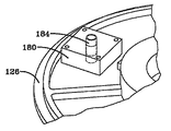
本発明は、遠心圧縮機用の可変形状ディフューザー機構である。図1は、異なるディフューザー構造を有する先行技術による可変容量遠心圧縮機を示している。この先行技術のシステムは、可動壁を、インペラの出口に隣接して配置された環状リングとして使用している。この壁は、通常そうであるように、ディフューザーを通る流体の流れを制御するためにディフューザー空間内へ動かすことができる。環状リングは、基板上に配置されている。リングは、環状プッシュリングと壁に接続されたピンを含んでいる壁を動かすための複雑な支持構造体に接続されている。駆動リングは、玉軸受け装置を介して基板に取り付けられている。駆動リングは環状プッシュリングを押し、環状プッシュリングが壁を動かす。玉軸受け装置は、駆動リングのレースと基板の傾斜したレースに載っている。従って、何らかの適切な機構による駆動リングの回転運動によって、可動壁が軸方向に運動してディフューザーの空間に出入りする。この装置の構成と作動に関する更に詳細な説明は、本発明の譲受人に譲渡されている2000年10月31日発行の米国特許第6,139,262号に記載されており、同特許を参考文献としてここに援用する。 The present invention is a variable shape diffuser mechanism for a centrifugal compressor. FIG. 1 shows a prior art variable capacity centrifugal compressor having a different diffuser structure. This prior art system uses the movable wall as an annular ring located adjacent to the impeller outlet. This wall can be moved into the diffuser space to control fluid flow through the diffuser, as is usually the case. The annular ring is disposed on the substrate. The ring is connected to a complex support structure for moving the wall including an annular push ring and a pin connected to the wall. The drive ring is attached to the substrate via a ball bearing device. The drive ring pushes the annular push ring, which moves the wall. The ball bearing device rests on the race of the drive ring and the inclined race of the substrate. Thus, the rotational movement of the drive ring by any suitable mechanism causes the movable wall to move in the axial direction and enter and exit the diffuser space. A more detailed description of the construction and operation of this device can be found in US Pat. No. 6,139,262 issued October 31, 2000, assigned to the assignee of the present invention, and is hereby incorporated by reference. Incorporated herein by reference.
図2は、本発明の可変形状ディフューザー110を有する遠心圧縮機100の断面図である。図2に示しているように、圧縮機100は、ハウジング又はディフューザープレート120と、インペラ124と、ノズル基板126とを含んでいる。ディフューザーリング130は、本発明の可変形状ディフューザー110の一部であるが、ノズル基板126内へと機械加工された溝132に組み込まれている。ディフューザーリング130は、溝132から外へ、ディフューザープレート120とノズル基板126を分離しているディフューザー間隙134内へと動かすことができる。完全に引っ込んだ位置では、ディフューザーリング130は、ノズル基板126内の溝132内に填り込んで、ディフューザー間隙134は、最大流量の状態にある。完全に伸張した位置では、ディフューザーリング130は、実質的にディフューザー間隙134を横切って伸張し、基本的にディフューザー間隙134を閉じる。ディフューザーリング130は、完全引込位置と完全伸張位置の間の何れの位置にでも動かすことができる。
FIG. 2 is a cross-sectional view of a
圧縮機へ向かう流体の流れは、図1に符号26で示している入口案内翼によって制御され、入口案内翼は、圧縮機を通過する流体の方向を制御し流量を調整するため、制限された様式でその軸の回りに回転させることができる。入口案内翼26は、遠心圧縮機毎に位置がそれほど変わるわけではなく、インペラの上流に配置されており、その位置が本発明の作動にとって重要ではないので、他の図面には示していない。回転の範囲に亘る翼26の回転は、圧縮機の容量を変化させる。翼26は、通常、位置センサーの様なその相対位置を判定するための手段を含んでいるので、圧縮機を通る流体の流れを判定して、必要に応じて作動器で流量を調節することができるようになっている。
The flow of fluid toward the compressor is controlled by an inlet guide vane, indicated at 26 in FIG. 1, which is restricted to control the direction of the fluid passing through the compressor and regulate the flow rate. Can be rotated around its axis in a manner. The
通常は冷媒か又は潤滑油ミストと混合した冷媒の形態をしている流体は、入口案内翼26を通過した後、インペラ24(図1)又は124(図2)に流れ込む。インペラ124の回転は、流体に仕事量を付与し、それによってその圧力を上げる。当該技術では周知のように、高圧の流体は、インペラを出て、ディフューザー間隙134を通過し、最終的には圧縮機出口に向かう。
The fluid, usually in the form of refrigerant or refrigerant mixed with lubricating oil mist, passes through the
圧縮機の負荷が下がると、入口案内翼26は回転して、インペラ124に供給する流体の流量を減らす。しかしながら、インペラ24の前後で同じ圧力が維持されると、圧縮機を出る流体の流れは不定になり、逆流して先に論じたサージ状態を作り出しかねない。サージ状態を防ぐために、流量の低下に応じて、ディフューザー間隙134を小さくしてインペラ出口の面積を減らし、流体の流れを安定させる。ディフューザー間隙134は、図3に示すように、ディフューザーリング130を間隙134内へと動かしてその面積を減らすか、或いは、図4の最大流量状態に示すように、ディフューザーリング130を溝 132内へと後退させて面積を増やすことによって、制御される。
本発明の可変形状ディフューザー110の構造と作動について、図面を参照しながら以下に詳細に説明する。
When the compressor load is reduced, the
The structure and operation of the
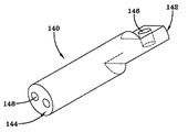
本発明の可変形状ディフューザー110は、ディフューザーリング130を備えている。ディフューザーリング130は、駆動ピン140に取り付けられている。図5に示すように、駆動ピン140は、第1端142と、ディフューザーリング130と係合する第2端144を有している。駆動ピン140の第1端142には、カム従動子穴146が設けられている。駆動ピン140の第2端144には、駆動ピン140をディフューザーリング130へ取り付けるための手段が設けられている。好適な実施形態では、取り付けるための手段は、図示の少なくとも1つの穴148であり、一対のねじ付穴を含んでいる。
The
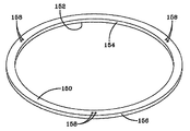
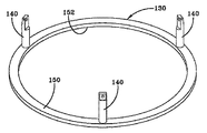
図6に示しているディフューザーリング130は、第1面150と、反対側の第2面152と、第1面150と第2面152の間に伸張する内周壁154と、第1面150と第2面152の間に伸張し、内周壁154と実質的に同心の外周壁156とを有している。ディフューザーリング130は、内周壁154と外周壁156の間の距離で決まる所定の厚さと、第1面150と反対側の第2面152の間の距離で決まる所定の軸方向長さを有している。複数の穴158が、ディフューザーリング130の軸方向長さを貫通して伸張し、駆動ピン140とディフューザーリング130の間の取り付け手段の一部を形成している。この好適な実施形態に示しているように、複数の穴は、三対の穴158を含んでいる。各対の穴158は、駆動ピンの穴148に対応するように、リング130上に配置されている。ディフューザーリング130の第2面152(図5に図示せず)は、駆動ピン140の面に隣接して組み付けられる。第2面152には、必要であれば、随意的に、駆動ピン140を受け入れる座ぐり穴を穴158の反対側に設けてもよい。図7は、複数の駆動ピン140がディフューザーリング130に組み付けられている状態を示している。穴158を貫通して駆動ピン140の穴148内へと伸張するねじ付きファスナーが、駆動ピン140をディフューザーリングに固定している。図示のように、駆動ピン140のディフューザーリング130への取り付け手段は、穴158を貫通して穴148内に伸張しているねじ付きファスナーを含んでいる。しかしながら、取り付け手段はこれに限定されるものではなく、既知の機械的締結手段を使用してもよい。例えば、駆動ピンの第2端144にねじを切って、ディフューザーリングにねじ込んでもよい。代わりに、駆動ピン140を、例えばタック溶接で、リング130に固定してもよい。ピン140をディフューザーリング130に固定する手段は重要ではなく、どの様な手段でこれらの部品を一体化してもよい。
The
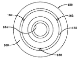
図8は、ノズル基板126の前側160の斜視図である。溝132は、ノズル基板126の円周に沿って伸張している。複数の穴162が、溝132内でノズル基板126を貫通している。これらの穴には、ディフューザーリング130が取り付けられた駆動ピン140が差し込まれる。図8に示す好適な実施形態では、約120°間隔で3つの穴が配置されている。大きな中央の穴164には、インペラ124が取り付けられている圧縮機100の駆動シャフト(図示せず)が入る。
FIG. 8 is a perspective view of the
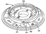
図9は、ノズル基板126の裏側170を示している。ノズル基板126の裏側には、複数の支持ブロック180が取り付けられている。支持ブロック180は、基板170に組み付けられる別々の部品でもよく、後付け用には最も有用である。或いは、支持ブロック180は、ノズル基板170と一体の部分であってもよい。最も一般的には、これらのブロックは、鋳造の基板形状に組み込まれている。図9に示す好適な実施形態では、3つの支持ブロック180がある。各支持ブロックは、支持ブロック180を貫通する主要穴182を含んでいる。支持ブロック180は、支持ブロック180を貫通する各主要穴182が、ノズル基板126を貫通する各穴162と同軸になるように、基板126の裏側170に組み付けられている。これらの同軸の穴162、182には、それぞれ、駆動ピン140が差し込まれるが、以下に詳細に説明する。
FIG. 9 shows the
図10は、基板126に組み付けられた支持ブロック180の拡大斜視図である。ブッシング184が、穴182に組み込まれている。或る好適な実施形態では、このブッシング184は、テフロン(登録商標)被覆されており、穴182に圧入嵌めされている。駆動ピン140は、基板126に組み付けられた支持ブロック180に駆動ピン140が組み付けられている図11の拡大図に示すように、ブッシング184に滑動可能に挿入されている。
FIG. 10 is an enlarged perspective view of the
図11と図12に示すように、駆動ピンの第1端142は、支持ブロック180の上方に伸張している。図12に示すように、駆動ピンの第1端142は、カム従動子穴146の軸に垂直な平坦面190を有している。どの様な形状を利用してもよいが、この形状によって、カム従動子200を駆動ピンの第1端142に容易に組み付けることができるようになる。カム従動子200は、穴146を通して組み付けられ、ナット202で駆動ピン126に固定される。カム従動子200が自由に回転できさえすれば、例えばロックピン装置など、どの様な手段でカム従動子200を駆動ピン126に固定してもよい。好適な手段には、容易に組み立て、分解できる手段が含まれる。
As shown in FIGS. 11 and 12, the
図13は、駆動リング250の斜視図である。駆動リング250は、外周面252と内周面254を含んでおり、共に、その上面256と下面258の間を伸張している。駆動リング250の軸方向長さは、上面256と下面258の間の軸方向距離であり、駆動リング250の軸は、上面と下面256と258を通って伸張する面を貫通してその面に垂直に伸張する仮想線であり、この軸は、概ね駆動リング250の幾何学中心に位置している。内周面254に沿って、内周溝260が設けられている。溝260は、以下に説明するように、軸方向軸受を受け入れるための予め選択された幅を有している。図13に示すように、内周溝260は、容易に製造するため、内周面254に沿って360°伸張している。後に明らかになるが、溝260は、360°伸張していなければならないわけではない。1つだけしか図示していないが、外周面252には、複数のカム軌道262が設けられている。カム軌道262は、外周面252に、カム従動子200を受け入れるために予め選択された深さと幅で作られた溝である。各カム軌道262は、支持ブロック180に対応し、これと嵌合するのが理想的である。従って、3つの支持ブロック160を描いている図9に示した好適な実施形態では、駆動リング250は、3つの対応するカム軌道262を有することになる。カム軌道262は、上面256と下面258の間を、駆動リングの軸に対して或る予め選択された角度で外周面に沿って伸張する溝を備えている。溝は、カム軌道262の一方の端部に、過剰移動を許容するため、上面256と下面258に実質的に平行な円周部分264を含んでいる。溝は、下面258に近接するカム軌道の端部に、カム従動子200のアッセンブリが溝へ出入りできるようにするため下面258へと伸張する部分268を含んでいる。部分268は、駆動リング250の主軸に実質的に平行に図示しているが、組み付け易い形状であればどの様な形状でもよい。例えば、部分268は、水平方向から上向きに上面256まで伸張してもよい。カム軌道262は、2つの成分、即ち、駆動リング250の軸に平行な成分と、駆動リング250の回りに円周状に駆動リング250の軸に対して半径方向に伸張する成分とを有している。カム軌道262が駆動リング250の軸に平行に伸張する距離は、ディフューザー間隙134の幅に実質的に相当する。カムシャフト溝の角度は、予め選択されたどの様な角度でもよい。その角度が浅くなるほど、駆動リング250の制御、従って拡散リング130の制御が、正確になる。しかしながら、この角度には下限があり、それは、駆動リング250の直径と、駆動リング250の外径のカム従動子の数によって決まる。角度が大きくなれば、駆動リング250の位置決めは難しくなる。カムシャフト溝の角度は、駆動リング250の軸に対して約5°―45°の間であるのが望ましく、約7°から約14°の範囲内であるのが最も望ましい。
FIG. 13 is a perspective view of the
図14は、支持ブロック180に組み付けられた駆動リング250の斜視図である。支持ブロック180は、駆動リング250の下側に伸張している。支持ブロック180は、ノズル基板126に組み付けられている。図11に示すように、駆動ピン140は、支持ブロック180に組み込まれて、ノズル基板126を貫通して下へと伸張している。図14では見えないが、図12に示しているように構成されているカム従動子200は、カム軌道262に組み込まれている。図14で分かるように、支持ブロック180は、駆動リング250の下面258の下側を伸張している。
FIG. 14 is a perspective view of the
図15は、駆動リング250の下側を伸張している支持ブロック180の1つの斜視図である。この図は、駆動リング250の内周面254と内周溝260を示している。軸受ブロック180には、軸方向軸受アッセンブリ280と半径方向軸受アッセンブリ290が組み付けられている。
FIG. 15 is a perspective view of one of the support blocks 180 extending under the
軸方向軸受アッセンブリ280の斜視図を、図16に示す。軸方向軸受アッセンブリ280は、軸方向軸受284の支持構造体282と、支持構造体282を支持ブロック180に固定する取付手段286を備えている。シャフト(図示せず)が、支持構造体282を貫通して伸張している。シャフトの一端には、ブッシング284が設けられており、このブッシングは偏心しているのが望ましい。好適な実施形態に示しているように、取付手段286は、実質的に、支持ブロック180の連結穴に捕捉されている一対のねじ付き部材である。支持構造体282を支持ブロック180に固定するのに、他の周知のどの様な手段を使用してもよい。図15に戻るが、軸方向軸受284は、固定手段288によって支持ブロック282に取り付けられている。図15に示すように、軸方向軸受284を支持ブロック282に固定するための手段は、支持ブロック282を貫通して伸張するシャフトのねじ付き端部に締め付けられたナットである。ブッシング285は、このシャフトの反対側の端部の回りに自由に回転する。この場合も、軸方向軸受284を内周溝260に面する位置に固定するのに、他のどの様な装置を使用してもよい。図15に示すように、軸方向軸受284(視野から隠れている)は、内周溝260に組み込まれている。軸方向軸受284は、駆動リング250が回転するときに、駆動リングの軸方向運動を阻む。軸方向軸受284は、駆動リング250の軸方向運動を阻むだけでなく、駆動リング250の軸方向の位置を微妙に調整できるようにしている。この調整は、駆動ピン140の長さのばらつきに対処するために必要である。軸方向軸受284のシャフトに装着された偏心ブッシング285によって、調整が可能になる。軸方向軸受284を駆動リング250に組み付けた後、駆動ピンのカム従動子200が穴266の隣りのカム軌道262の行程の端部にくるように、駆動リング250が回される。これによって、軸方向軸受284が、カム軌道262に隣接する穴266と整列する。図19に示しているこの位置で、六角(アレン)レンチの様な工具を、穴266を通して、レンチヘッドと合致する造形部、ここでは軸方向軸受284に設けられたレンチの六角頭部と整合する六角穴に挿入することができる。軸方向軸受284は、必要なら駆動リング250のブッシング285に対する軸方向位置を調整するため、時計回りか反時計回りに回される。位置が正しくなると、軸方向軸受284は、シャフトの反対側の端部のナットを締めることによって固定される。駆動リング250の好適な調整は、ディフューザーリングが一杯に引っ込んだ位置にあるときに、ディフューザーリング130の面が、ノズル基板125の面と同面になるようにすることである。
A perspective view of the
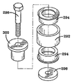
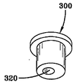
図15は、支持ブロック180上に取り付けられた半径方向軸受アッセンブリ290も示している。図17は、半径方向軸受アッセンブリ290の分解図を示している。半径方向軸受アッセンブリ290は、ローラー292と、ローラー292に装着されている少なくとも1つのブッシング294と、ローラー292の片側に1つづつの、望ましくは2つのフランジ付きブッシング294を備えている。フランジ付きのレース300が、前記少なくとも1つのブッシング294の中に組み込まれている。或る好適な実施形態では、一対のフランジ付きブッシング294は、ローラー292の片側に1つづつ装着されている2つのテフロン(登録商標)・フランジ付きブッシングで構成されている。一部にねじが切られたシャフト296が、レース300を貫通して伸張し、アッセンブリを支持ブロック180に固定している。座金298が、ローラー292と支持ブロック180の間に加えられている。半径方向軸受アッセンブリ290の内の1つは、図20に示すように、フランジ付きレース300に偏心して穿孔された取付穴320を採用している。この偏心した取付穴によって、半径方向軸受290を調整することができる。この調整は、駆動リング250の内径のばらつきを補正するのに必要である。好適な調整とは、全ての半径方向軸受を、駆動リング250の内側表面と丁度接触させることである。半径方向軸受アッセンブリ290は、駆動リング250が回転するときに、駆動リングの半径方向の運動を阻む。駆動リング250が回転するときに、駆動リングの半径方向運動を阻むことができるのであれば、他の適切などの様な半径方向軸受アッセンブリを使用してもよい。
FIG. 15 also shows a
この機構の作動について、図2、3、4並びに図18を参照しながら以下に説明する。図18は、駆動リング250の上面256に取り付けられている作動手段310の斜視図である。図18に示すように、作動手段310は、軸方向にだけ動く機械式の作動器であり、これを動かすモーターに取り付けられている。機械式作動器を用いているが、駆動リング250を回転させるのには、油圧作動器、空圧作動器、駆動リング250に取り付けられているねじ機構、又はリング250を回転させることのできる他のシステムを含め、他の既知のどの様な手段を使用してもよい。そのストロークの方向と長さは、制限されている。作動器の軸方向の運動が、駆動リングを回転させる。モーターは、弁護士訴訟事件一覧表20712−0059「遠心圧縮機の回転失速を検出するためのシステム及び方法」として特定されている仮特許出願に記載されている様な制御手段に応答して起動する。しかしながら、作動器には他のどの様な制御手段を使用してもよい。図4に示しているようにディフューザーリングが引込位置にあり、圧縮機が通常のモードで作動しているときに、失速又は初生サージの開始をセンサーが検出すると、信号が制御器に送られ、制御器がディフューザー間隙134を閉じる方向にモーターを起動する。モーターは、作動手段310を動かし、作動手段310が駆動リング250を回転させる。駆動リング250は、駆動リングが支持ブロック180上に載っている面内での回転運動に制約されている。駆動リング250が回転するにつれ、各カム従動子200は、カム軌道の溝が駆動リング250の上面256に近接しているカム軌道262の第1位置から、軌道に沿って、駆動リング250の下面258へ向かって動く。駆動リング250とカム軌道262が回転するにつれ、カム従動子200は、軌道262に沿って下向きに押される。従動子が下向きに動くと、駆動ピン140は支持ブロック180の中へと動く。ディフューザーリング130は、ノズル基板126の反対側で駆動ピン140の反対側の端部に取り付けられているので、駆動ピン140が支持ブロック180の中へと動くと、駆動ピン140の反対側はノズル基板から離れる方向に動き、ディフューザーリング130をディフューザー間隙134の中へと動かす。カム従動子200が、カム軌道262内を、上面256に近い位置から、下面258に近い位置まで完全に移動すると、ディフューザー間隙134は、実質的に一杯に絞られた、即ち閉じられた状態になる。カム軌道262の水平溝部分264が、作動手段310とカム従動子200の過剰移動に配慮しているので、これらの要素が多少動き過ぎても、拡散リング130が更に動いて、圧縮機100、駆動リング250、作動手段310及び作動手段モーターの1つ又は全てに損傷を与えることのないようになっている。
The operation of this mechanism will be described below with reference to FIGS. FIG. 18 is a perspective view of the actuating means 310 attached to the
制御システムに従って、作動手段310は、駆動リング250の回転を、作動手段310の一杯に伸張した位置と一杯に引っ込んだ位置の間の任意の中間の位置で停止することもできる。作動手段310は、これを制御手段からの信号に応じて行う。その結果、ディフューザーリング130は、図4に示す一杯に引っ込んだ位置と図3に示す一杯に伸張した位置の間の、図2に示す中間位置の様な任意の位置に止められることになる。ディフューザーリングは、制御手段からの信号が駆動リング250の追加の運動を引き起こし、その結果ディフューザーリング130が位置決めし直されるまで、この位置に留まる。
According to the control system, the actuating means 310 can also stop the rotation of the
或る好適な実施形態では、サージ又は初生失速の開始の検出を示す信号が制御手段に送信されると、先に述べたように駆動リング250を回転させる1つの指令(又は一連の指令)が起動され、それによって、サージ又は初生失速を取り除くか、或いはサージ又は失速状態の形成を防ぐのに必要な量だけ、ディフューザーリング130が伸張位置まで動かされる(ディフューザー間隙134を通る流体の流れを実質的に絞る)。或る実施形態では、タイミング関数が、ディフューザーリング130を所望の位置に維持する制御器内で起動される。予め選択された期間の終わりに、駆動リング250は反対方向に回され、それによって、ディフューザーリング130は、サージ又は初生失速の開始が再び検出されるまで引込位置へ動かされる。センサーの信号に応じて上記プロセスが繰り返され、1つの指令(又は一連の指令)が再び起動され、駆動リング250を回転させ、ディフューザーリング130を動かし又は伸張させて、ディフューザー間隙134を通る流体の流れを、サージ又は初生失速状態を取り除くのに必要な量だけ再び絞る。このプロセスは、サージ又は初生失速状態が検出される限り繰り返される。ディフューザーリング130が引っ込んでいるときにサージ又は初生失速状態が検出されなければ、ディフューザーリング130は、一杯に引っ込んだ位置、即ち開位置まで引っ込んだ状態を続けるので、冷媒の流れ全てがディフューザー間隙134を通過することができる。ディフューザーリング130は、制御手段が、サージ又は初生失速の開始を示す信号に応じて、1つの指令又は一連の指令を起動させるまで、この位置に留まる。
In a preferred embodiment, when a signal is sent to the control means indicating the start of a surge or initial stall, a command (or series of commands) to rotate the
以上、本発明を、好適な実施形態を参照しながら説明してきたが、当業者には理解頂けるように、本発明の範囲を逸脱することなく、様々な変更を加え、その要素を等価物で置き換えることもできる。更に、本発明の本質的な範囲から逸脱することなく、特定の状況又は材料を本発明の教示に適合させるため、多くの修正を加えることができる。従って、本発明は、本発明を実行するために考えられる最良の方式として開示した特定の実施形態に限定されるものではなく、特許請求の範囲に述べる内容に該当するの全ての実施形態を包含するものとする。 Although the present invention has been described with reference to the preferred embodiments, it will be understood by those skilled in the art that various modifications can be made without departing from the scope of the present invention, and the elements can be equivalents. It can also be replaced. In addition, many modifications may be made to adapt a particular situation or material to the teachings of the invention without departing from the essential scope thereof. Accordingly, the invention is not limited to the specific embodiments disclosed as the best mode contemplated for carrying out the invention, but encompasses all embodiments that fall within the scope of the claims. It shall be.
100 圧縮機
110 ディフューザー
124 インペラ
126 ノズル基板
130 ディフューザーリング
134 ディフューザー間隙
180 支持ブロック
250 駆動リング
280 軸方向軸受アッセンブリ
290 半径方向軸受アッセンブリ
100
Claims (36)
前記インペラに隣接して前記ハウジングに接続されているノズル基板であって、前記ハウジングの相対する内側表面と協働してディフューザー間隙を画定する細長い表面を有しており、前記細長い表面は前記ディフューザー間隙に隣接する溝を有している、ノズル基板と、
前記ノズル基板の、前記ディフューザー間隙とは反対側の、裏側に取り付けられている複数の支持ブロックと、
前記支持ブロックに回転可能に取り付けられており、第1位置と第2位置との間で動くことができる駆動リングであって、前記駆動リングの外周上に配置されている複数のカム軌道を含んでおり、前記複数のカム軌道の内の少なくとも2つは、前記複数の支持ブロックの内の少なくとも2つと整列している、駆動リングと、
前記駆動リングに取り付けられており、第1軸方向位置と第2軸方向位置との間を動いて、前記駆動リングを前記第1位置と前記第2位置との間で動かすことができる作動手段と、
複数の駆動ピンであって、各駆動ピンは、対応する前記支持ブロックと前記ノズル基板を貫通して伸張しており、前記各駆動ピンは、第1端と、前記第1端の反対側の第2端を有しており、前記駆動ピンの前記第1端は、前記駆動リングのカム軌道内に取り付けられるカム従動子を含んでおり、前記駆動ピンの前記第2端は、前記ノズル基板を貫通して、前記ノズル基板の表面の溝の中に伸張している、駆動ピンと、
前記複数の駆動ピンそれぞれの前記第2端に取り付けられているディフューザーリングであって、前記駆動ピンは、前記ノズル基板表面の溝の中に伸張している、ディフューザーリングと、を備えており、
前記駆動リングの第1位置と第2位置の間の回転運動は、前記カム従動子を前記カム軌道内で動かして前記駆動ピンを軸方向に動かし、前記駆動ピンの前記軸方向運動は、前記ディフューザーリングを、前記ディフューザーリングが前記ノズル基板の前記溝の中に在る引込位置と、前記ディフューザーリングが前記ディフューザー間隙を実質的に閉じて前記ディフューザー間隙を通る流体の流れを減らす伸張位置との間で動かす、システム。 A diffuser system for a variable displacement centrifugal compressor for compressing a fluid, the compressor having a housing and an impeller, the impeller being rotatably mounted in the housing In
A nozzle substrate connected to the housing adjacent to the impeller and having an elongated surface that cooperates with an opposing inner surface of the housing to define a diffuser gap, the elongated surface being the diffuser A nozzle substrate having a groove adjacent to the gap;
A plurality of support blocks attached to the back side of the nozzle substrate opposite to the diffuser gap;
A drive ring rotatably mounted on the support block and capable of moving between a first position and a second position, comprising a plurality of cam tracks disposed on an outer periphery of the drive ring And at least two of the plurality of cam tracks are aligned with at least two of the plurality of support blocks;
Actuating means attached to the drive ring and capable of moving between a first axial position and a second axial position to move the drive ring between the first position and the second position. When,
A plurality of drive pins, wherein each drive pin extends through the corresponding support block and the nozzle substrate, and each drive pin has a first end and an opposite side of the first end. The drive pin has a second end, the first end of the drive pin includes a cam follower mounted in a cam track of the drive ring, and the second end of the drive pin is the nozzle substrate A drive pin extending through the groove in the surface of the nozzle substrate,
A diffuser ring attached to the second end of each of the plurality of drive pins, the drive pin comprising: a diffuser ring extending into a groove in the surface of the nozzle substrate;
The rotational movement between the first position and the second position of the drive ring moves the cam follower in the cam track to move the drive pin in the axial direction, and the axial movement of the drive pin A diffuser ring, a retracted position in which the diffuser ring is in the groove of the nozzle substrate; and an extended position in which the diffuser ring substantially closes the diffuser gap and reduces fluid flow through the diffuser gap. A system that moves between.
ハウジングと、
流体入口と、
前記入口を通して導入される流体を圧縮するために、前記ハウジング内でシャフトに回転可能に取り付けられているインペラアッセンブリと、
前記インペラから圧縮された流体を放出するための流体出口と、
前記インペラに隣接して前記ハウジングに接続されているノズル基板であって、前記ハウジングの相対する内側表面と協働してディフューザー間隙を画定する細長い表面を有しているノズル基板と、
前記ノズル基板の、前記ディフューザー間隙とは反対側の、裏側に配置されている複数の支持ブロックと、
前記支持ブロックに回転可能に取り付けられており、第1位置と第2位置の間を動くことのできる駆動リングであって、前記駆動リングの外周上に配置されている複数のカム軌道を含んでおり、前記複数のカム軌道の内の少なくとも2つは、前記複数の支持ブロックの内の少なくとも2つと整列している、駆動リングと、
軸方向に動くことができ、前記駆動リングに取り付けられていて、前記駆動リングを前記第1位置と前記第2位置の間で動かすために、第1軸方向位置と第2軸方向位置の間を動くことのできる作動手段と、
複数の駆動ピンであって、各駆動ピンは、対応する前記支持ブロックと前記ノズル基板を通って伸張しており、前記各駆動ピンは、第1端と、前記第1端と反対側の第2端を有しており、前記駆動ピンの前記第1端は、前記駆動リング上の前記複数のカム軌道の1つに取り付けられているカム従動子を含んでおり、前記駆動ピンの前記第2端は、前記ノズル基板を貫通して伸張し、前記細長い表面から突き出ている、駆動ピンと、
前記ノズル基板表面から突き出ている前記複数の駆動ピンそれぞれの前記第2端に取り付けられているディフューザーリングと、を備えており、
前記駆動リングが第1位置と第2位置の間で回転運動することによって、前記駆動ピンを軸方向に動かす前記カム軌道内で前記カム従動子が動き、前記駆動ピンが前記軸方向に動くことによって、前記ディフューザーリングが、前記ディフューザーリングが前記ハウジングの前記相対する内側表面から遠くにあって前記ディフューザー間隙を通る流体の流れを増している引込位置と、前記ディフューザーリングが前記ハウジングの前記相対する内側表面の近くにあって前記ディフューザー間隙を実質的に閉じて前記ディフューザー間隙を通る流体の流れを減らしている伸張位置との間で動くことになる、遠心圧縮機。 In centrifugal compressor,
A housing;
A fluid inlet;
An impeller assembly rotatably mounted on a shaft within the housing for compressing fluid introduced through the inlet;
A fluid outlet for discharging compressed fluid from the impeller;
A nozzle substrate connected to the housing adjacent to the impeller and having an elongated surface that cooperates with opposing inner surfaces of the housing to define a diffuser gap;
A plurality of support blocks arranged on the back side of the nozzle substrate opposite to the diffuser gap;
A drive ring rotatably attached to the support block and capable of moving between a first position and a second position, comprising a plurality of cam tracks disposed on an outer periphery of the drive ring A drive ring, wherein at least two of the plurality of cam tracks are aligned with at least two of the plurality of support blocks;
Between the first axial position and the second axial position to be movable in an axial direction and attached to the drive ring for moving the drive ring between the first position and the second position. An actuating means capable of moving,
A plurality of drive pins, each drive pin extending through the corresponding support block and the nozzle substrate, each drive pin having a first end and a first end opposite to the first end; The first end of the drive pin includes a cam follower attached to one of the plurality of cam tracks on the drive ring, the first end of the drive pin Two ends extending through the nozzle substrate and projecting from the elongated surface;
A diffuser ring attached to the second end of each of the plurality of drive pins protruding from the surface of the nozzle substrate,
When the drive ring rotates between the first position and the second position, the cam follower moves in the cam track that moves the drive pin in the axial direction, and the drive pin moves in the axial direction. The diffuser ring is in a retracted position where the diffuser ring is remote from the opposing inner surface of the housing to increase fluid flow through the diffuser gap, and the diffuser ring is the opposite of the housing. A centrifugal compressor that is moved between an extended position near an inner surface that substantially closes the diffuser gap and reduces fluid flow through the diffuser gap.
Applications Claiming Priority (2)
| Application Number | Priority Date | Filing Date | Title |
|---|---|---|---|
| US10/313,364 | 2002-12-06 | ||
| US10/313,364 US6872050B2 (en) | 2002-12-06 | 2002-12-06 | Variable geometry diffuser mechanism |
Related Parent Applications (1)
| Application Number | Title | Priority Date | Filing Date |
|---|---|---|---|
| JP2004559192A Division JP4500687B2 (en) | 2002-12-06 | 2003-12-02 | Diffuser system for variable capacity centrifugal compressors |
Publications (2)
| Publication Number | Publication Date |
|---|---|
| JP2010031876A true JP2010031876A (en) | 2010-02-12 |
| JP5442398B2 JP5442398B2 (en) | 2014-03-12 |
Family
ID=32468233
Family Applications (2)
| Application Number | Title | Priority Date | Filing Date |
|---|---|---|---|
| JP2004559192A Expired - Lifetime JP4500687B2 (en) | 2002-12-06 | 2003-12-02 | Diffuser system for variable capacity centrifugal compressors |
| JP2009257762A Expired - Lifetime JP5442398B2 (en) | 2002-12-06 | 2009-11-11 | Diffuser system |
Family Applications Before (1)
| Application Number | Title | Priority Date | Filing Date |
|---|---|---|---|
| JP2004559192A Expired - Lifetime JP4500687B2 (en) | 2002-12-06 | 2003-12-02 | Diffuser system for variable capacity centrifugal compressors |
Country Status (9)
| Country | Link |
|---|---|
| US (1) | US6872050B2 (en) |
| EP (1) | EP1570181B1 (en) |
| JP (2) | JP4500687B2 (en) |
| KR (1) | KR100748398B1 (en) |
| CN (1) | CN1745253B (en) |
| AU (1) | AU2003293178A1 (en) |
| CA (1) | CA2507409C (en) |
| TW (1) | TWI238224B (en) |
| WO (1) | WO2004053336A1 (en) |
Cited By (4)
| Publication number | Priority date | Publication date | Assignee | Title |
|---|---|---|---|---|
| JP2015524033A (en) * | 2012-11-09 | 2015-08-20 | ジョンソン コントロールズ テクノロジー カンパニーJohnson Controls Technology Company | Variable form diffuser with extended stroke and control method thereof |
| DE102015220333A1 (en) * | 2015-10-19 | 2017-04-20 | Rolls-Royce Deutschland Ltd & Co Kg | Device for adjusting a gap between the housing of an impeller and the impeller in a centrifugal compressor and a turbomachine |
| KR20200057061A (en) * | 2017-09-25 | 2020-05-25 | 존슨 컨트롤스 테크놀러지 컴퍼니 | Compact variable geometry diffuser mechanism |
| JP2020535344A (en) * | 2017-09-25 | 2020-12-03 | ジョンソン コントロールズ テクノロジー カンパニーJohnson Controls Technology Company | Two-part split scroll for centrifugal compressors |
Families Citing this family (59)
| Publication number | Priority date | Publication date | Assignee | Title |
|---|---|---|---|---|
| US7356999B2 (en) * | 2003-10-10 | 2008-04-15 | York International Corporation | System and method for stability control in a centrifugal compressor |
| US7905102B2 (en) * | 2003-10-10 | 2011-03-15 | Johnson Controls Technology Company | Control system |
| DE102004047103A1 (en) * | 2004-09-29 | 2006-04-13 | Bayerische Motoren Werke Ag | turbocharger |
| US20070196206A1 (en) * | 2006-02-17 | 2007-08-23 | Honeywell International, Inc. | Pressure load compressor diffuser |
| EP1965037B1 (en) | 2007-03-02 | 2016-12-14 | Siemens Aktiengesellschaft | Axial and radial support of the unison ring for inlet guide vane assemblies of hot gas expanders |
| EP1965036A1 (en) * | 2007-03-02 | 2008-09-03 | Siemens Aktiengesellschaft | Turbomachine with adjustable shroud contour |
| US7905702B2 (en) * | 2007-03-23 | 2011-03-15 | Johnson Controls Technology Company | Method for detecting rotating stall in a compressor |
| US20080276613A1 (en) * | 2007-05-09 | 2008-11-13 | Phillipe Noelle | Discrete variable geometry compressor |
| US7871243B2 (en) * | 2007-06-05 | 2011-01-18 | Honeywell International Inc. | Augmented vaneless diffuser containment |
| EP2014925A1 (en) * | 2007-07-12 | 2009-01-14 | ABB Turbo Systems AG | Diffuser for radial compressors |
| TWI437167B (en) * | 2007-10-31 | 2014-05-11 | Johnson Controls Tech Co | Control system |
| KR100909779B1 (en) * | 2008-02-01 | 2009-07-29 | 엘에스엠트론 주식회사 | Variable diffuser of compressor |
| US7975506B2 (en) | 2008-02-20 | 2011-07-12 | Trane International, Inc. | Coaxial economizer assembly and method |
| US9353765B2 (en) | 2008-02-20 | 2016-05-31 | Trane International Inc. | Centrifugal compressor assembly and method |
| US8037713B2 (en) | 2008-02-20 | 2011-10-18 | Trane International, Inc. | Centrifugal compressor assembly and method |
| US7856834B2 (en) * | 2008-02-20 | 2010-12-28 | Trane International Inc. | Centrifugal compressor assembly and method |
| JP5291363B2 (en) * | 2008-03-14 | 2013-09-18 | 三菱重工業株式会社 | pump |
| US8438855B2 (en) * | 2008-07-24 | 2013-05-14 | General Electric Company | Slotted compressor diffuser and related method |
| KR101080954B1 (en) * | 2009-03-05 | 2011-11-08 | 주식회사 에어젠 | Gas compressor and method for controlling flow rate thereof |
| KR101066968B1 (en) * | 2009-03-05 | 2011-09-22 | 주식회사 에어젠 | Gas compressor and method for controlling flow rate thereof |
| JP5394509B2 (en) * | 2009-03-05 | 2014-01-22 | エアゼン・カンパニー・リミテッド | Gas compressor |
| GB2470050B (en) * | 2009-05-07 | 2015-09-23 | Cummins Turbo Tech Ltd | A compressor |
| KR101350695B1 (en) | 2009-06-05 | 2014-01-10 | 존슨 컨트롤스 테크놀러지 컴퍼니 | Control system |
| US8307646B2 (en) * | 2009-08-04 | 2012-11-13 | International Engine Intellectual Property Company, Llc | System using supplemental compressor for EGR |
| US9217592B2 (en) * | 2010-11-17 | 2015-12-22 | Johnson Controls Technology Company | Method and apparatus for variable refrigerant chiller operation |
| TWI418711B (en) * | 2010-11-25 | 2013-12-11 | Ind Tech Res Inst | A mechanism for modulating diffuser vane of diffuser |
| EP2655890B1 (en) * | 2010-12-22 | 2019-01-23 | Danfoss A/S | Variable-speed oil-free refrigerant centrifugal compressor with variable geometry diffuser |
| JP5574040B2 (en) * | 2011-03-23 | 2014-08-20 | トヨタ自動車株式会社 | Centrifugal compressor |
| US9810228B2 (en) * | 2011-09-14 | 2017-11-07 | Danfoss A/S | Centrifugal compressor diffuser control |
| WO2013133832A2 (en) * | 2012-03-08 | 2013-09-12 | Danfoss Turbocor Compressors B.V. | High pressure ratio multi-stage centrifugal compressor |
| WO2013165841A1 (en) | 2012-04-30 | 2013-11-07 | Johnson Controls Technology Company | Control system |
| US9341193B2 (en) | 2013-04-04 | 2016-05-17 | Hamilton Sundstrand Corporation | Cabin air compressor diffuser vane drive ring |
| CN104421209B (en) * | 2013-08-26 | 2017-02-08 | 珠海格力电器股份有限公司 | regulator structure and centrifugal compressor |
| CN104653476B (en) * | 2013-11-18 | 2017-11-14 | 珠海格力电器股份有限公司 | Centrifugal compressor and centrifugal water chilling unit |
| RU2674479C2 (en) * | 2014-02-24 | 2018-12-11 | ДжиИ ОЙЛ ЭНД ГЭС ЭСП, ИНК. | Downhole wet gas compressor processor |
| GB201408087D0 (en) | 2014-05-07 | 2014-06-18 | Cummins Ltd | Variable geometry turbine assembly |
| US9568018B2 (en) | 2014-05-30 | 2017-02-14 | Hamilton Sundstrand Corporation | Cover plate for cabin air compressor |
| CN104131999B (en) * | 2014-07-23 | 2017-07-28 | 珠海格力电器股份有限公司 | Centrifugal compressor's regulation structure and centrifugal compressor |
| GB2531029B (en) * | 2014-10-07 | 2020-11-18 | Cummins Ltd | Compressor and turbocharger |
| CN104454653A (en) * | 2014-11-20 | 2015-03-25 | 辽宁长志泵业有限公司 | Device for adjusting special performance of axially split pump |
| CN104533838B (en) * | 2014-12-18 | 2017-06-06 | 珠海格力电器股份有限公司 | Adjustable diffuser |
| US11274705B2 (en) | 2016-02-19 | 2022-03-15 | Johnson Controls Technology Company | Vapor compression system and method of extending service life of same |
| GB2551804B (en) | 2016-06-30 | 2021-04-07 | Cummins Ltd | Diffuser for a centrifugal compressor |
| CN107975498B (en) | 2016-10-24 | 2021-08-31 | 开利公司 | Diffuser for centrifugal compressor and centrifugal compressor with diffuser |
| TWI607185B (en) | 2016-12-09 | 2017-12-01 | 財團法人工業技術研究院 | Modulating mechanism of centrifugal compressor |
| RU2716940C1 (en) | 2018-02-09 | 2020-03-17 | Кэрриер Корпорейшн | Centrifugal compressor with recirculation channel |
| CN110360130B (en) * | 2018-04-09 | 2022-12-27 | 开利公司 | Variable diffuser drive system |
| CN109356886A (en) | 2018-12-17 | 2019-02-19 | 珠海格力电器股份有限公司 | Centrifugal compressor and diffuser device |
| TWI692584B (en) * | 2019-11-05 | 2020-05-01 | 財團法人工業技術研究院 | Centrifugal compressor |
| CN112983846A (en) | 2019-12-02 | 2021-06-18 | 开利公司 | Centrifugal compressor and method for operating a centrifugal compressor |
| CN110821872A (en) * | 2019-12-10 | 2020-02-21 | 南京磁谷科技有限公司 | Air inlet channel and impeller clearance adjusting structure |
| EP4107402A4 (en) | 2020-02-20 | 2023-04-05 | Danfoss A/S | Axial magnetic bearing for centrifugal refrigerant compressor |
| CN115380165A (en) * | 2020-02-27 | 2022-11-22 | 江森自控泰科知识产权控股有限责任合伙公司 | System and method for using a variable geometry diffuser as a check valve |
| US11391289B2 (en) | 2020-04-30 | 2022-07-19 | Trane International Inc. | Interstage capacity control valve with side stream flow distribution and flow regulation for multi-stage centrifugal compressors |
| US11536277B2 (en) | 2020-04-30 | 2022-12-27 | Trane International Inc. | Interstage capacity control valve with side stream flow distribution and flow regulation for multi-stage centrifugal compressors |
| EP4177476A1 (en) * | 2021-11-03 | 2023-05-10 | Trane International Inc. | Interstage capacity control valve with side stream flow distribution and flow regulation for multi-stage centrifugal compressors |
| US11841026B2 (en) | 2021-11-03 | 2023-12-12 | Trane International Inc. | Compressor interstage throttle, and method of operating therof |
| CN114278615B (en) * | 2021-12-21 | 2024-03-19 | 麦克维尔空调制冷(苏州)有限公司 | Flexibly connected diffuser structure based on cam transmission |
| CN115076141A (en) * | 2022-07-22 | 2022-09-20 | 山东天瑞重工有限公司 | Flow regulating device and centrifugal compressor |
Citations (3)
| Publication number | Priority date | Publication date | Assignee | Title |
|---|---|---|---|---|
| US3478955A (en) * | 1968-03-11 | 1969-11-18 | Dresser Ind | Variable area diffuser for compressor |
| JPS5092509A (en) * | 1973-12-21 | 1975-07-24 | ||
| US6139262A (en) * | 1998-05-08 | 2000-10-31 | York International Corporation | Variable geometry diffuser |
Family Cites Families (22)
| Publication number | Priority date | Publication date | Assignee | Title |
|---|---|---|---|---|
| NL98031C (en) | 1957-12-23 | |||
| US3251539A (en) | 1963-05-15 | 1966-05-17 | Westinghouse Electric Corp | Centrifugal gas compressors |
| US3289919A (en) | 1964-11-16 | 1966-12-06 | Westinghouse Electric Corp | Centrifugal gas compressors |
| US3941498A (en) | 1974-04-08 | 1976-03-02 | Chandler Evans Inc. | Variable geometry collector for centrifugal pump |
| US3904312A (en) | 1974-06-12 | 1975-09-09 | Avco Corp | Radial flow compressors |
| US3992128A (en) | 1975-06-09 | 1976-11-16 | General Motors Corporation | Variable diffuser |
| USRE31835E (en) | 1980-11-24 | 1985-02-19 | United Technologies Corporation | Pneumatic supply system having variable geometry compressor |
| US4403914A (en) | 1981-07-13 | 1983-09-13 | Teledyne Industries, Inc. | Variable geometry device for turbomachinery |
| US4718819A (en) | 1983-02-25 | 1988-01-12 | Teledyne Industries, Inc. | Variable geometry device for turbine compressor outlet |
| US4579509A (en) | 1983-09-22 | 1986-04-01 | Dresser Industries, Inc. | Diffuser construction for a centrifugal compressor |
| US4503684A (en) | 1983-12-19 | 1985-03-12 | Carrier Corporation | Control apparatus for centrifugal compressor |
| US4844690A (en) * | 1985-01-24 | 1989-07-04 | Carrier Corporation | Diffuser vane seal for a centrifugal compressor |
| US4616483A (en) | 1985-04-29 | 1986-10-14 | Carrier Corporation | Diffuser wall control |
| US4611969A (en) | 1985-08-19 | 1986-09-16 | Carrier Corporation | Calibrating apparatus and method for a movable diffuser wall in a centrifugal compressor |
| US4780049A (en) | 1986-06-02 | 1988-10-25 | Palmer Lynn D | Compressor |
| US5146764A (en) | 1990-07-25 | 1992-09-15 | York International Corporation | System and method for controlling a variable geometry diffuser to minimize noise |
| US5116197A (en) | 1990-10-31 | 1992-05-26 | York International Corporation | Variable geometry diffuser |
| US5207559A (en) * | 1991-07-25 | 1993-05-04 | Allied-Signal Inc. | Variable geometry diffuser assembly |
| US6036432A (en) * | 1998-07-09 | 2000-03-14 | Carrier Corporation | Method and apparatus for protecting centrifugal compressors from rotating stall vibrations |
| US6158956A (en) | 1998-10-05 | 2000-12-12 | Allied Signal Inc. | Actuating mechanism for sliding vane variable geometry turbine |
| US6361432B1 (en) | 1999-08-17 | 2002-03-26 | Tomkins Industries, Inc. | Air diffuser with air flow regulator |
| JP2002048098A (en) | 2000-08-02 | 2002-02-15 | Mitsubishi Heavy Ind Ltd | Routing guide for bulk material |
-
2002
- 2002-12-06 US US10/313,364 patent/US6872050B2/en not_active Expired - Lifetime
-
2003
- 2003-12-02 CA CA002507409A patent/CA2507409C/en not_active Expired - Fee Related
- 2003-12-02 EP EP03790169A patent/EP1570181B1/en not_active Expired - Lifetime
- 2003-12-02 KR KR1020057010263A patent/KR100748398B1/en active IP Right Grant
- 2003-12-02 JP JP2004559192A patent/JP4500687B2/en not_active Expired - Lifetime
- 2003-12-02 AU AU2003293178A patent/AU2003293178A1/en not_active Abandoned
- 2003-12-02 WO PCT/US2003/038073 patent/WO2004053336A1/en active Application Filing
- 2003-12-02 CN CN2003801094627A patent/CN1745253B/en not_active Expired - Lifetime
- 2003-12-05 TW TW092134367A patent/TWI238224B/en not_active IP Right Cessation
-
2009
- 2009-11-11 JP JP2009257762A patent/JP5442398B2/en not_active Expired - Lifetime
Patent Citations (3)
| Publication number | Priority date | Publication date | Assignee | Title |
|---|---|---|---|---|
| US3478955A (en) * | 1968-03-11 | 1969-11-18 | Dresser Ind | Variable area diffuser for compressor |
| JPS5092509A (en) * | 1973-12-21 | 1975-07-24 | ||
| US6139262A (en) * | 1998-05-08 | 2000-10-31 | York International Corporation | Variable geometry diffuser |
Cited By (13)
| Publication number | Priority date | Publication date | Assignee | Title |
|---|---|---|---|---|
| JP2015524033A (en) * | 2012-11-09 | 2015-08-20 | ジョンソン コントロールズ テクノロジー カンパニーJohnson Controls Technology Company | Variable form diffuser with extended stroke and control method thereof |
| JP2016196892A (en) * | 2012-11-09 | 2016-11-24 | ジョンソン コントロールズ テクノロジー カンパニーJohnson Controls Technology Company | Variable geometry diffuser having extended stroke, and its control method |
| US11092166B2 (en) | 2012-11-09 | 2021-08-17 | Johnson Controls Technology Company | Variable geometry diffuser having extended travel and control method thereof |
| JP2017166490A (en) * | 2012-11-09 | 2017-09-21 | ジョンソン コントロールズ テクノロジー カンパニーJohnson Controls Technology Company | Variable geometry diffuser having extended stroke, and control method of the same |
| JP2017166489A (en) * | 2012-11-09 | 2017-09-21 | ジョンソン コントロールズ テクノロジー カンパニーJohnson Controls Technology Company | Variable geometry diffuser with extended stroke and its controlling method |
| US10378553B2 (en) | 2012-11-09 | 2019-08-13 | Johnson Controls Technology Company | Variable geometry diffuser having extended travel and control method thereof |
| US10465705B2 (en) | 2015-10-19 | 2019-11-05 | Rolls-Royce Deutschland Ltd & Co Kg | Device for adjusting a gap between the housing of an impeller and the impeller in a radial compressor and a turbomachine |
| DE102015220333A1 (en) * | 2015-10-19 | 2017-04-20 | Rolls-Royce Deutschland Ltd & Co Kg | Device for adjusting a gap between the housing of an impeller and the impeller in a centrifugal compressor and a turbomachine |
| KR20200057061A (en) * | 2017-09-25 | 2020-05-25 | 존슨 컨트롤스 테크놀러지 컴퍼니 | Compact variable geometry diffuser mechanism |
| JP2020535345A (en) * | 2017-09-25 | 2020-12-03 | ジョンソン コントロールズ テクノロジー カンパニーJohnson Controls Technology Company | Compact variable shape diffuser mechanism |
| JP2020535344A (en) * | 2017-09-25 | 2020-12-03 | ジョンソン コントロールズ テクノロジー カンパニーJohnson Controls Technology Company | Two-part split scroll for centrifugal compressors |
| JP7220208B2 (en) | 2017-09-25 | 2023-02-09 | ジョンソン コントロールズ テクノロジー カンパニー | Compact variable geometry diffuser mechanism |
| KR102572313B1 (en) * | 2017-09-25 | 2023-08-29 | 존슨 컨트롤스 테크놀러지 컴퍼니 | Compact variable geometry diffuser mechanism |
Also Published As
| Publication number | Publication date |
|---|---|
| TW200417692A (en) | 2004-09-16 |
| CA2507409C (en) | 2008-10-07 |
| EP1570181B1 (en) | 2011-11-16 |
| CA2507409A1 (en) | 2004-06-24 |
| WO2004053336A1 (en) | 2004-06-24 |
| JP5442398B2 (en) | 2014-03-12 |
| US20040109757A1 (en) | 2004-06-10 |
| KR20050085407A (en) | 2005-08-29 |
| JP2006509155A (en) | 2006-03-16 |
| US6872050B2 (en) | 2005-03-29 |
| TWI238224B (en) | 2005-08-21 |
| KR100748398B1 (en) | 2007-08-10 |
| AU2003293178A1 (en) | 2004-06-30 |
| CN1745253B (en) | 2010-06-09 |
| EP1570181A1 (en) | 2005-09-07 |
| JP4500687B2 (en) | 2010-07-14 |
| CN1745253A (en) | 2006-03-08 |
Similar Documents
| Publication | Publication Date | Title |
|---|---|---|
| JP5442398B2 (en) | Diffuser system | |
| US6139262A (en) | Variable geometry diffuser | |
| US9200640B2 (en) | Inlet guide vane for a compressor | |
| EP2024645B1 (en) | Geared inlet guide vane for a centrifugal compressor | |
| TWI525256B (en) | Variable geometry diffuser having extended travel and method for controlling refrigerant flow in a centrifugal compressor | |
| SE517007C2 (en) | Drive device for a worm-type machine | |
| JP3307919B2 (en) | Valve device for fluid piping | |
| JP6206638B2 (en) | Centrifugal compressor | |
| EP1321679B1 (en) | Drive position mechanism with backlash adjustment for variable pipe diffuser | |
| JP2004138065A (en) | Method and device for adjusting fluid flow of gas turbine engine | |
| US6461129B2 (en) | Scroll type compressor apparatus with adjustable axial gap | |
| JPH0656110B2 (en) | Metering valve | |
| US6506011B1 (en) | Method for limiting split ring diffuser travel | |
| CN108278132B (en) | Variable turbine and/or compressor geometry for an exhaust gas turbocharger | |
| CN100436757C (en) | Variable diffuser with movable wall | |
| CN115076141A (en) | Flow regulating device and centrifugal compressor | |
| CN117167330A (en) | Centrifugal compressor and control method thereof |
Legal Events
| Date | Code | Title | Description |
|---|---|---|---|
| A621 | Written request for application examination |
Free format text: JAPANESE INTERMEDIATE CODE: A621 Effective date: 20091111 |
|
| A131 | Notification of reasons for refusal |
Free format text: JAPANESE INTERMEDIATE CODE: A131 Effective date: 20120201 |
|
| A601 | Written request for extension of time |
Free format text: JAPANESE INTERMEDIATE CODE: A601 Effective date: 20120501 |
|
| A602 | Written permission of extension of time |
Free format text: JAPANESE INTERMEDIATE CODE: A602 Effective date: 20120508 |
|
| A521 | Request for written amendment filed |
Free format text: JAPANESE INTERMEDIATE CODE: A523 Effective date: 20120601 |
|
| A131 | Notification of reasons for refusal |
Free format text: JAPANESE INTERMEDIATE CODE: A131 Effective date: 20130107 |
|
| A601 | Written request for extension of time |
Free format text: JAPANESE INTERMEDIATE CODE: A601 Effective date: 20130405 |
|
| A602 | Written permission of extension of time |
Free format text: JAPANESE INTERMEDIATE CODE: A602 Effective date: 20130410 |
|
| A521 | Request for written amendment filed |
Free format text: JAPANESE INTERMEDIATE CODE: A523 Effective date: 20130507 |
|
| TRDD | Decision of grant or rejection written | ||
| A01 | Written decision to grant a patent or to grant a registration (utility model) |
Free format text: JAPANESE INTERMEDIATE CODE: A01 Effective date: 20131202 |
|
| A61 | First payment of annual fees (during grant procedure) |
Free format text: JAPANESE INTERMEDIATE CODE: A61 Effective date: 20131218 |
|
| R150 | Certificate of patent or registration of utility model |
Ref document number: 5442398 Country of ref document: JP Free format text: JAPANESE INTERMEDIATE CODE: R150 Free format text: JAPANESE INTERMEDIATE CODE: R150 |
|
| R250 | Receipt of annual fees |
Free format text: JAPANESE INTERMEDIATE CODE: R250 |
|
| R250 | Receipt of annual fees |
Free format text: JAPANESE INTERMEDIATE CODE: R250 |
|
| R250 | Receipt of annual fees |
Free format text: JAPANESE INTERMEDIATE CODE: R250 |
|
| R250 | Receipt of annual fees |
Free format text: JAPANESE INTERMEDIATE CODE: R250 |
|
| R250 | Receipt of annual fees |
Free format text: JAPANESE INTERMEDIATE CODE: R250 |
|
| R250 | Receipt of annual fees |
Free format text: JAPANESE INTERMEDIATE CODE: R250 |
|
| R250 | Receipt of annual fees |
Free format text: JAPANESE INTERMEDIATE CODE: R250 |
|
| EXPY | Cancellation because of completion of term |