JP2010031861A - System and method for providing supercritical cooling steam into wheel space of turbine - Google Patents
System and method for providing supercritical cooling steam into wheel space of turbine Download PDFInfo
- Publication number
- JP2010031861A JP2010031861A JP2009167337A JP2009167337A JP2010031861A JP 2010031861 A JP2010031861 A JP 2010031861A JP 2009167337 A JP2009167337 A JP 2009167337A JP 2009167337 A JP2009167337 A JP 2009167337A JP 2010031861 A JP2010031861 A JP 2010031861A
- Authority
- JP
- Japan
- Prior art keywords
- turbomachine
- housing
- turbine
- diaphragm
- cooling steam
- Prior art date
- Legal status (The legal status is an assumption and is not a legal conclusion. Google has not performed a legal analysis and makes no representation as to the accuracy of the status listed.)
- Granted
Links
Images

Classifications
-
- F—MECHANICAL ENGINEERING; LIGHTING; HEATING; WEAPONS; BLASTING
- F01—MACHINES OR ENGINES IN GENERAL; ENGINE PLANTS IN GENERAL; STEAM ENGINES
- F01D—NON-POSITIVE DISPLACEMENT MACHINES OR ENGINES, e.g. STEAM TURBINES
- F01D11/00—Preventing or minimising internal leakage of working-fluid, e.g. between stages
- F01D11/001—Preventing or minimising internal leakage of working-fluid, e.g. between stages for sealing space between stator blade and rotor
-
- F—MECHANICAL ENGINEERING; LIGHTING; HEATING; WEAPONS; BLASTING
- F01—MACHINES OR ENGINES IN GENERAL; ENGINE PLANTS IN GENERAL; STEAM ENGINES
- F01D—NON-POSITIVE DISPLACEMENT MACHINES OR ENGINES, e.g. STEAM TURBINES
- F01D25/00—Component parts, details, or accessories, not provided for in, or of interest apart from, other groups
- F01D25/08—Cooling; Heating; Heat-insulation
- F01D25/14—Casings modified therefor
-
- F—MECHANICAL ENGINEERING; LIGHTING; HEATING; WEAPONS; BLASTING
- F01—MACHINES OR ENGINES IN GENERAL; ENGINE PLANTS IN GENERAL; STEAM ENGINES
- F01D—NON-POSITIVE DISPLACEMENT MACHINES OR ENGINES, e.g. STEAM TURBINES
- F01D5/00—Blades; Blade-carrying members; Heating, heat-insulating, cooling or antivibration means on the blades or the members
- F01D5/02—Blade-carrying members, e.g. rotors
- F01D5/08—Heating, heat-insulating or cooling means
- F01D5/081—Cooling fluid being directed on the side of the rotor disc or at the roots of the blades
- F01D5/082—Cooling fluid being directed on the side of the rotor disc or at the roots of the blades on the side of the rotor disc
-
- F—MECHANICAL ENGINEERING; LIGHTING; HEATING; WEAPONS; BLASTING
- F01—MACHINES OR ENGINES IN GENERAL; ENGINE PLANTS IN GENERAL; STEAM ENGINES
- F01D—NON-POSITIVE DISPLACEMENT MACHINES OR ENGINES, e.g. STEAM TURBINES
- F01D9/00—Stators
- F01D9/02—Nozzles; Nozzle boxes; Stator blades; Guide conduits, e.g. individual nozzles
- F01D9/04—Nozzles; Nozzle boxes; Stator blades; Guide conduits, e.g. individual nozzles forming ring or sector
- F01D9/047—Nozzle boxes
-
- F—MECHANICAL ENGINEERING; LIGHTING; HEATING; WEAPONS; BLASTING
- F05—INDEXING SCHEMES RELATING TO ENGINES OR PUMPS IN VARIOUS SUBCLASSES OF CLASSES F01-F04
- F05D—INDEXING SCHEME FOR ASPECTS RELATING TO NON-POSITIVE-DISPLACEMENT MACHINES OR ENGINES, GAS-TURBINES OR JET-PROPULSION PLANTS
- F05D2220/00—Application
- F05D2220/30—Application in turbines
- F05D2220/31—Application in turbines in steam turbines
Abstract
Description
本発明は、ターボ機械のタービン内の金属応力を制限するためにボイラから供給する冷却蒸気の使用に関する。 The present invention relates to the use of cooling steam supplied from a boiler to limit metal stress in a turbine of a turbomachine.
国際公開第01/86121号には、蒸気タービンの高圧膨脹セクション内でシャフトを冷却する方法が開示されている。蒸気発生器は、シャフトを冷却するために該蒸気発生器から取出される冷却蒸気よりもそれぞれ高い温度及び低い圧力を有する生蒸気を生成するように構成される。高圧膨脹セクションには、冷却蒸気用供給源が設けられる。 WO 01/86121 discloses a method for cooling a shaft in a high pressure expansion section of a steam turbine. The steam generator is configured to produce live steam having a higher temperature and lower pressure, respectively, than the cooling steam removed from the steam generator to cool the shaft. The high pressure expansion section is provided with a cooling steam source.
特開平09−250306号には、ボイラの中間段で生じる蒸気に高圧初期段ノズル出口漏洩蒸気を混合させて、中圧初期段バケットスタッド部の物質力が低下するのを防止することが開示されている。 Japanese Patent Application Laid-Open No. 09-250306 discloses that high-pressure initial stage nozzle outlet leakage steam is mixed with steam generated in an intermediate stage of a boiler to prevent a decrease in material force of an intermediate-pressure initial stage bucket stud. ing.
本発明の1つの実施形態では、ターボ機械の高圧セクションを冷却するためのシステムは、ボイラからターボ機械の第1段ノズルの上流のスペースに冷却蒸気を運ぶように構成された導管を含む。導管は、ターボ機械のハウジング及び第1段ノズルのノズルダイヤフラムを貫通して延びる。本システムはさらに、導管内に設けられかつ冷却蒸気の流れを制御するように構成された制御バルブを含む。 In one embodiment of the present invention, a system for cooling a high pressure section of a turbomachine includes a conduit configured to carry cooling steam from a boiler to a space upstream of a turbomachine first stage nozzle. The conduit extends through the turbomachine housing and the nozzle diaphragm of the first stage nozzle. The system further includes a control valve provided in the conduit and configured to control the flow of cooling steam.
本発明の別の実施形態では、ターボ機械は、ハウジングと、該ハウジング内に回転可能に支持されたタービンシャフトと、該タービンシャフトに沿って設置されかつハウジング内に収容された複数のタービン段とを含む。各タービン段は、ハウジングに取付けられたダイヤフラムを含む。ダイヤフラムは、複数のノズルを含む。孔が、冷却蒸気の導入のために複数の段の第1段の上流でダイヤフラム内に設けられる。 In another embodiment of the present invention, a turbomachine includes a housing, a turbine shaft rotatably supported in the housing, and a plurality of turbine stages installed along the turbine shaft and housed in the housing. including. Each turbine stage includes a diaphragm attached to the housing. The diaphragm includes a plurality of nozzles. A hole is provided in the diaphragm upstream of the first stage of the plurality of stages for the introduction of cooling steam.
本発明のさらに別の実施形態では、ターボ機械の高圧セクションを冷却する方法を提供する。ターボ機械は、ハウジングと、該ハウジング内に回転可能に支持されたタービンシャフトと、該タービンシャフトに沿って設置されかつハウジング内に収容された複数のタービン段とを含む。各タービン段は、ハウジングに取付けられたダイヤフラムを含む。ダイヤフラムは、複数のノズルと、複数の段の第1段の上流で該ダイヤフラム内に設けられた少なくとも1つの孔とを含む。本方法は、少なくとも1つの孔を通してターボ機械内に冷却蒸気を導入するステップを含む。 In yet another embodiment of the present invention, a method for cooling a high pressure section of a turbomachine is provided. The turbomachine includes a housing, a turbine shaft rotatably supported in the housing, and a plurality of turbine stages installed along the turbine shaft and housed in the housing. Each turbine stage includes a diaphragm attached to the housing. The diaphragm includes a plurality of nozzles and at least one hole provided in the diaphragm upstream of the first stage of the plurality of stages. The method includes introducing cooling steam into the turbomachine through at least one hole.
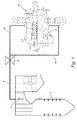
図1を参照すると、ボイラは、ターボ機械のタービン24に蒸気を供給するように構成されている。ボイラ2は、複数の過熱器又は再熱器を含む。図1に示すように、導管又はパイプ8は、ボイラ2の最終過熱器4に設けられて、タービン24に冷却蒸気を供給する。
Referring to FIG. 1, the boiler is configured to supply steam to a
パイプ8は、タービン24の負荷要件に従って冷却蒸気の流れ(冷却蒸気流(量))を調整する(制御)するのを可能にする制御バルブ6を有する。冷却蒸気流は、パイプ8に沿って移動し、タービン24の外側ハウジング又はシェル20を貫通して該タービン24に供給される。パイプ8は、第1の分岐管8aと第2の分岐管8bとに分岐される。
The
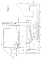
図2を参照すると、冷却蒸気は、第1及び第2の分岐管8a及び8bに沿ってタービン24の外側シェル20を貫通して第1段上流ホイールスペース内に導入される。図2には、第2の分岐管8bのみを示しているが、タービン24の外側シェル20の下半分には第1の分岐管8aが設けられることを理解されたい。
Referring to FIG. 2, cooling steam is introduced into the first stage upstream wheel space through the
図2を参照すると、タービン24は複数の蒸気方向付けノズルを含む。図2に示すように、冷却蒸気パイプ8の第2の分岐管8bのすぐ下流には、第1段ノズル30が設けられている。蒸気方向付けノズル30は、ノズルダイヤフラム26を含み、ノズルダイヤフラム26は外側リング部分28とノズルダイヤフラム内側リング部分22とを含む。ノズルダイヤフラム26は、ハウジング又はシェル20に取付けられかつタービンブラケット又はブレード14及ノズル30を囲む。タービンブレード14は、タービン24のロータ10のホイール12上に支持される。
Referring to FIG. 2, the
ノズルダイヤフラム内側リング部分22は、該ノズルダイヤフラム内側リング部分22とロータ10の外側表面との間に設けられたシール16を支持する。ノズルダイヤフラム外側リング28は、タービンブレード14を囲むスピルストリップシールリング18を支持する。タービンブレード14には、該タービンブレード14の外側半径方向表面上にカバーを設けることができることを理解されたい。
The nozzle diaphragm
図2に示すように、冷却蒸気は、導管又はパイプ8から第2の分岐管8b内に供給され、タービン24のハウジング又はシェル20を貫通して第1段蒸留ホイールスペースに至る。冷却蒸気は、シェル20の上及び下半分の両方内において、例えば該シェル20及びノズルダイヤフラム26内に穴をドリル加工し、かつステライト嵌合装置を使用することによって第1段ノズル30の上流に供給される。
As shown in FIG. 2, cooling steam is supplied from a conduit or
図3を参照すると、冷却蒸気流は、2つの分岐管8a及び8bを通ってタービン24のシェル20の高圧(HP)部分に流入し、次に第1段上流ホイールスペース内に導かれ、それによって第1段上流ホイールスペースを多量のより低温の蒸気で満たす。冷却流は次に、蒸気バランス孔を通って下流ホイールスペースに移動し、次にパッキンリング16を通って第2段上流ホイールスペースに流れる。スピルストリップシールリング18を使用して主蒸気流から冷却回路を分離する。これにより図3に示すような蛇行冷却構成が得られる。
Referring to FIG. 3, the cooling steam flow passes through the two
高圧膨張タービン24内において、高反動全周第1段を使用することによって冷却蒸気がタービン24の高圧領域に供給され、またその圧力がタービン24のスロットル圧力よりも高いことが必要な場合には冷却流がボイラ2から供給されるので、冷却蒸気により、タービン24内の金属応力が制限される。
In the high
制御バルブ6は、タービン24の負荷要件に合わせて冷却流を調整するのを可能にすることによって、該冷却流を制御するように使用される。これにより、タービン24の性能を悪化させずに高効率低反動第1段の使用が可能になる。従って、図1〜図3に示す構成はタービン24を広い負荷範囲にわたって作動させるのを可能にし、またボイラ2からの外部蒸気冷却流の使用はタービン24の広い負荷範囲にわたる最大効率を可能にする。
The control valve 6 is used to control the cooling flow by allowing it to be adjusted to the load requirements of the
現在、最も実用的かつ好ましい実施形態であると考えられるものに関して本発明を説明してきたが、本発明は開示した実施形態に限定されるものではなく、逆に特許請求の範囲の技術思想及び技術的範囲内に含まれる様々な変更及び均等な構成を保護しようとするものであることを理解されたい。 Although the present invention has been described with respect to what is considered to be the most practical and preferred embodiments, the invention is not limited to the disclosed embodiments, but conversely, the technical ideas and techniques of the claims It should be understood that various changes and equivalent arrangements included within the scope are intended to be protected.
2 ボイラ
4 最終過熱器
6 制御バルブ
8 冷却蒸気パイプ又は導管
8a 第1の分岐管
8b 第2の分岐管
10 ロータ
12 ホイール
14 タービンブレード
16 パッキンリング
18 ストリップシールリング
20 外側ハウジング
22 ノズルダイヤフラム内側リング部分
24 タービン
26 ノズルダイヤフラム
28 ノズルダイヤフラム外側リング部分
30 第1段ノズル
2
Claims (10)
前記ターボ機械のハウジング(20)及び該ターボ機械の第1段ノズル(30)のノズルダイヤフラム(26)を貫通して延びかつボイラ(2)から前記第1段ノズルの上流のスペースに冷却蒸気を運ぶように構成された導管(8)と、
前記導管内に設けられかつ前記冷却蒸気の流れを制御するように構成された制御バルブ(6)と
を含むシステム。 A system for cooling a high-pressure section of a turbomachine,
Cooling steam extends through the housing (20) of the turbomachine and the nozzle diaphragm (26) of the first stage nozzle (30) of the turbomachine and from the boiler (2) to the space upstream of the first stage nozzle. A conduit (8) configured to carry;
A control valve (6) provided in the conduit and configured to control the flow of the cooling steam.
前記ハウジング内に回転可能に支持されたタービンシャフト(10)と、
前記タービンシャフトに沿って設置されかつ前記ハウジング内に収容された複数のタービン段と
を含むターボ機械であって、各タービン段が前記ハウジングに取付けられたダイヤフラム(26)を含み、前記ダイヤフラムが複数のノズル(30)を含み、少なくとも1つの孔が、冷却蒸気の導入のために前記複数の段の第1段の上流で前記ダイヤフラム内に設けられる、ターボ機械。 A housing (20);
A turbine shaft (10) rotatably supported in the housing;
A turbomachine including a plurality of turbine stages installed along the turbine shaft and housed in the housing, each turbine stage including a diaphragm (26) attached to the housing, wherein the plurality of diaphragms A turbomachine wherein at least one hole is provided in the diaphragm upstream of the first stage of the plurality of stages for introduction of cooling steam.
前記少なくとも1つの孔を通して前記ターボ機械内に冷却蒸気を導入するステップ、
を含む方法。 Each turbine stage includes a housing (20), a turbine shaft (10) rotatably supported in the housing, and a plurality of turbine stages installed along the turbine shaft and housed in the housing. Includes a diaphragm (26) attached to the housing, the diaphragm including a plurality of nozzles (30) and at least one hole provided in the diaphragm upstream of the first stage of the plurality of stages. A method for cooling a high-pressure section of a turbomachine,
Introducing cooling steam into the turbomachine through the at least one hole;
Including methods.
をさらに含む、請求項8記載の方法。 Controlling the introduction of the cooling steam such that the pressure of the cooling steam is higher than the pressure of the main steam flow of the turbomachine through the nozzle according to the load on the turbomachine;
The method of claim 8, further comprising:
Applications Claiming Priority (2)
| Application Number | Priority Date | Filing Date | Title |
|---|---|---|---|
| US12/178,788 | 2008-07-24 | ||
| US12/178,788 US8167535B2 (en) | 2008-07-24 | 2008-07-24 | System and method for providing supercritical cooling steam into a wheelspace of a turbine |
Publications (3)
| Publication Number | Publication Date |
|---|---|
| JP2010031861A true JP2010031861A (en) | 2010-02-12 |
| JP2010031861A5 JP2010031861A5 (en) | 2012-08-30 |
| JP5709363B2 JP5709363B2 (en) | 2015-04-30 |
Family
ID=41428904
Family Applications (1)
| Application Number | Title | Priority Date | Filing Date |
|---|---|---|---|
| JP2009167337A Expired - Fee Related JP5709363B2 (en) | 2008-07-24 | 2009-07-16 | System and method for supplying supercritical cooling steam into the wheel space of a turbine |
Country Status (5)
| Country | Link |
|---|---|
| US (1) | US8167535B2 (en) |
| JP (1) | JP5709363B2 (en) |
| CN (1) | CN101634232A (en) |
| DE (1) | DE102009026153A1 (en) |
| FR (1) | FR2934312B1 (en) |
Cited By (1)
| Publication number | Priority date | Publication date | Assignee | Title |
|---|---|---|---|---|
| JP2015129512A (en) * | 2014-01-02 | 2015-07-16 | ゼネラル・エレクトリック・カンパニイ | Steam turbine and methods of assembling the same |
Families Citing this family (4)
| Publication number | Priority date | Publication date | Assignee | Title |
|---|---|---|---|---|
| WO2011077872A1 (en) * | 2009-12-21 | 2011-06-30 | 三菱重工業株式会社 | Cooling method and device in single-flow turbine |
| CN102146810A (en) * | 2010-02-10 | 2011-08-10 | 中国科学院工程热物理研究所 | Method for cooling high-temperature turbine blade by utilizing supercritical characteristics of working medium |
| US9057275B2 (en) * | 2012-06-04 | 2015-06-16 | Geneal Electric Company | Nozzle diaphragm inducer |
| US10260377B2 (en) * | 2017-02-03 | 2019-04-16 | Woodward, Inc. | Generating steam turbine performance maps |
Citations (3)
| Publication number | Priority date | Publication date | Assignee | Title |
|---|---|---|---|---|
| JPS58187501A (en) * | 1982-04-28 | 1983-11-01 | Toshiba Corp | Cooling device for rotor of steam turbine |
| JPS59175607U (en) * | 1983-05-13 | 1984-11-24 | 株式会社日立製作所 | Seal ring for axial flow fluid machinery |
| JPS6388209A (en) * | 1986-09-30 | 1988-04-19 | Toshiba Corp | Cooling device for super-high temperature/high pressure turbine |
Family Cites Families (20)
| Publication number | Priority date | Publication date | Assignee | Title |
|---|---|---|---|---|
| DE2435153B2 (en) * | 1974-07-22 | 1977-06-30 | Kraftwerk Union AG, 4330 Mülheim | TURBO MACHINE, IN PARTICULAR STEAM TURBINE WITH HIGH STEAM INLET TEMPERATURE |
| US4309873A (en) * | 1979-12-19 | 1982-01-12 | General Electric Company | Method and flow system for the control of turbine temperatures during bypass operation |
| JPS58113501A (en) * | 1981-12-28 | 1983-07-06 | Toshiba Corp | Cooling device of steam turbine |
| DE3209506A1 (en) * | 1982-03-16 | 1983-09-22 | Kraftwerk Union AG, 4330 Mülheim | AXIAL STEAM TURBINE IN PARTICULAR, IN PARTICULAR VERSION |
| JPS643202A (en) * | 1987-06-26 | 1989-01-09 | Toshiba Corp | Cooling device for steam turbine |
| US5253976A (en) * | 1991-11-19 | 1993-10-19 | General Electric Company | Integrated steam and air cooling for combined cycle gas turbines |
| US5340274A (en) * | 1991-11-19 | 1994-08-23 | General Electric Company | Integrated steam/air cooling system for gas turbines |
| US5320483A (en) * | 1992-12-30 | 1994-06-14 | General Electric Company | Steam and air cooling for stator stage of a turbine |
| JPH09250306A (en) | 1996-03-12 | 1997-09-22 | Toshiba Corp | Cooling device of steam turbine |
| JPH09317405A (en) * | 1996-05-29 | 1997-12-09 | Toshiba Corp | Cooling system for high-pressure, front stage rotor blade embedded part of steam turbine |
| CA2262050C (en) * | 1998-02-17 | 2003-07-08 | Mitsubishi Heavy Industries, Ltd. | Steam-cooling type gas turbine |
| KR20000071653A (en) * | 1999-04-15 | 2000-11-25 | 제이 엘. 차스킨, 버나드 스나이더, 아더엠. 킹 | Cooling supply system for stage 3 bucket of a gas turbine |
| EP1152125A1 (en) * | 2000-05-05 | 2001-11-07 | Siemens Aktiengesellschaft | Method and apparatus for the cooling of the inlet part of the axis of a steam turbine |
| EP1154123A1 (en) | 2000-05-10 | 2001-11-14 | Siemens Aktiengesellschaft | Method of cooling the shaft of a high pressure steam turbine |
| US6779972B2 (en) * | 2002-10-31 | 2004-08-24 | General Electric Company | Flowpath sealing and streamlining configuration for a turbine |
| EP1445427A1 (en) * | 2003-02-05 | 2004-08-11 | Siemens Aktiengesellschaft | Steam turbine and method of operating a steam turbine |
| DE50312764D1 (en) * | 2003-03-06 | 2010-07-15 | Siemens Ag | Method for cooling a turbomachine and turbomachine for this |
| EP1473442B1 (en) * | 2003-04-30 | 2014-04-23 | Kabushiki Kaisha Toshiba | Steam turbine, steam turbine plant and method of operating a steam turbine in a steam turbine plant |
| US6896482B2 (en) * | 2003-09-03 | 2005-05-24 | General Electric Company | Expanding sealing strips for steam turbines |
| RU2006139188A (en) * | 2004-06-01 | 2008-07-20 | Нобору МАСАДА (JP) | HIGH EFFICIENCY HEAT CYCLE DEVICE |
-
2008
- 2008-07-24 US US12/178,788 patent/US8167535B2/en active Active
-
2009
- 2009-07-10 DE DE102009026153A patent/DE102009026153A1/en not_active Withdrawn
- 2009-07-16 JP JP2009167337A patent/JP5709363B2/en not_active Expired - Fee Related
- 2009-07-16 FR FR0954907A patent/FR2934312B1/en not_active Expired - Fee Related
- 2009-07-23 CN CN200910165589A patent/CN101634232A/en active Pending
Patent Citations (3)
| Publication number | Priority date | Publication date | Assignee | Title |
|---|---|---|---|---|
| JPS58187501A (en) * | 1982-04-28 | 1983-11-01 | Toshiba Corp | Cooling device for rotor of steam turbine |
| JPS59175607U (en) * | 1983-05-13 | 1984-11-24 | 株式会社日立製作所 | Seal ring for axial flow fluid machinery |
| JPS6388209A (en) * | 1986-09-30 | 1988-04-19 | Toshiba Corp | Cooling device for super-high temperature/high pressure turbine |
Cited By (1)
| Publication number | Priority date | Publication date | Assignee | Title |
|---|---|---|---|---|
| JP2015129512A (en) * | 2014-01-02 | 2015-07-16 | ゼネラル・エレクトリック・カンパニイ | Steam turbine and methods of assembling the same |
Also Published As
| Publication number | Publication date |
|---|---|
| US8167535B2 (en) | 2012-05-01 |
| DE102009026153A1 (en) | 2010-01-28 |
| JP5709363B2 (en) | 2015-04-30 |
| CN101634232A (en) | 2010-01-27 |
| FR2934312A1 (en) | 2010-01-29 |
| FR2934312B1 (en) | 2017-06-09 |
| US20100021283A1 (en) | 2010-01-28 |
Similar Documents
| Publication | Publication Date | Title |
|---|---|---|
| US8359824B2 (en) | Heat recovery steam generator for a combined cycle power plant | |
| JP5709363B2 (en) | System and method for supplying supercritical cooling steam into the wheel space of a turbine | |
| JP5692966B2 (en) | Method and apparatus for cooling rotating parts inside a steam turbine | |
| US7635250B2 (en) | Apparatus and method for controlling leakage in steam turbines | |
| JP2007085348A (en) | Method and device for double flow turbine first stage cooling | |
| JP2007291966A (en) | Steam turbine and turbine rotor | |
| JP5698895B2 (en) | Method and system for assembling an exhaust hood for a turbine | |
| JP2011144704A (en) | Rotor cooling apparatus for steam turbine and steam turbine equipped with rotor cooling device | |
| JP2014020319A (en) | Seal device for turbine and thermal power generation system | |
| JP2010169091A (en) | System, method, and apparatus for controlling gas leakage in turbine | |
| US20160090861A1 (en) | Steam turbine | |
| JP5461798B2 (en) | Turbine system and method using internal leakage flow for cooling | |
| JP5317814B2 (en) | Steam turbine | |
| JP6285692B2 (en) | Steam turbine equipment | |
| JP2010031861A5 (en) | ||
| JP6416382B2 (en) | Steam turbine and method of operating steam turbine | |
| JP2009203984A (en) | Apparatus and method for cooling tub part of double flow turbine | |
| JP2005315122A (en) | Steam turbine | |
| JP2009275703A (en) | Device and method for first step cooling of double flow turbine | |
| JP4413732B2 (en) | Steam turbine plant | |
| JP2010261455A (en) | Steam turbine, steam turbine system, and method for operation thereof | |
| CA2953407C (en) | Turbomachine with an outer sealing and use of the turbomachine | |
| US20130078088A1 (en) | Steam turbine lp casing cylindrical struts between stages | |
| JP2013064328A (en) | System and method for cooling gas turbine | |
| JP2013050054A (en) | Steam turbine |
Legal Events
| Date | Code | Title | Description |
|---|---|---|---|
| A621 | Written request for application examination |
Free format text: JAPANESE INTERMEDIATE CODE: A621 Effective date: 20120711 |
|
| A521 | Request for written amendment filed |
Free format text: JAPANESE INTERMEDIATE CODE: A523 Effective date: 20120713 |
|
| A977 | Report on retrieval |
Free format text: JAPANESE INTERMEDIATE CODE: A971007 Effective date: 20130826 |
|
| A131 | Notification of reasons for refusal |
Free format text: JAPANESE INTERMEDIATE CODE: A131 Effective date: 20130903 |
|
| A601 | Written request for extension of time |
Free format text: JAPANESE INTERMEDIATE CODE: A601 Effective date: 20131203 |
|
| A602 | Written permission of extension of time |
Free format text: JAPANESE INTERMEDIATE CODE: A602 Effective date: 20131206 |
|
| A601 | Written request for extension of time |
Free format text: JAPANESE INTERMEDIATE CODE: A601 Effective date: 20131226 |
|
| A602 | Written permission of extension of time |
Free format text: JAPANESE INTERMEDIATE CODE: A602 Effective date: 20140107 |
|
| A601 | Written request for extension of time |
Free format text: JAPANESE INTERMEDIATE CODE: A601 Effective date: 20140131 |
|
| A602 | Written permission of extension of time |
Free format text: JAPANESE INTERMEDIATE CODE: A602 Effective date: 20140205 |
|
| A521 | Request for written amendment filed |
Free format text: JAPANESE INTERMEDIATE CODE: A523 Effective date: 20140303 |
|
| A02 | Decision of refusal |
Free format text: JAPANESE INTERMEDIATE CODE: A02 Effective date: 20140722 |
|
| A521 | Request for written amendment filed |
Free format text: JAPANESE INTERMEDIATE CODE: A523 Effective date: 20141121 |
|
| A911 | Transfer to examiner for re-examination before appeal (zenchi) |
Free format text: JAPANESE INTERMEDIATE CODE: A911 Effective date: 20141201 |
|
| TRDD | Decision of grant or rejection written | ||
| A01 | Written decision to grant a patent or to grant a registration (utility model) |
Free format text: JAPANESE INTERMEDIATE CODE: A01 Effective date: 20150203 |
|
| A61 | First payment of annual fees (during grant procedure) |
Free format text: JAPANESE INTERMEDIATE CODE: A61 Effective date: 20150303 |
|
| R150 | Certificate of patent or registration of utility model |
Ref document number: 5709363 Country of ref document: JP Free format text: JAPANESE INTERMEDIATE CODE: R150 |
|
| R250 | Receipt of annual fees |
Free format text: JAPANESE INTERMEDIATE CODE: R250 |
|
| R250 | Receipt of annual fees |
Free format text: JAPANESE INTERMEDIATE CODE: R250 |
|
| R250 | Receipt of annual fees |
Free format text: JAPANESE INTERMEDIATE CODE: R250 |
|
| R250 | Receipt of annual fees |
Free format text: JAPANESE INTERMEDIATE CODE: R250 |
|
| LAPS | Cancellation because of no payment of annual fees |