JP2010031841A - Method and system for controlling temperature of gas turbine engine - Google Patents
Method and system for controlling temperature of gas turbine engine Download PDFInfo
- Publication number
- JP2010031841A JP2010031841A JP2009125981A JP2009125981A JP2010031841A JP 2010031841 A JP2010031841 A JP 2010031841A JP 2009125981 A JP2009125981 A JP 2009125981A JP 2009125981 A JP2009125981 A JP 2009125981A JP 2010031841 A JP2010031841 A JP 2010031841A
- Authority
- JP
- Japan
- Prior art keywords
- engine
- model
- operating parameter
- sensors
- determined
- Prior art date
- Legal status (The legal status is an assumption and is not a legal conclusion. Google has not performed a legal analysis and makes no representation as to the accuracy of the status listed.)
- Granted
Links
- 238000000034 method Methods 0.000 title description 19
- 238000012423 maintenance Methods 0.000 claims abstract description 9
- 230000002950 deficient Effects 0.000 claims 1
- 230000015654 memory Effects 0.000 description 16
- 238000010586 diagram Methods 0.000 description 12
- 238000012545 processing Methods 0.000 description 9
- 239000003570 air Substances 0.000 description 7
- 238000012360 testing method Methods 0.000 description 7
- 238000012544 monitoring process Methods 0.000 description 5
- 230000003068 static effect Effects 0.000 description 5
- 238000004422 calculation algorithm Methods 0.000 description 4
- 238000005094 computer simulation Methods 0.000 description 4
- 238000003745 diagnosis Methods 0.000 description 4
- 238000004519 manufacturing process Methods 0.000 description 4
- 238000005259 measurement Methods 0.000 description 4
- 238000012549 training Methods 0.000 description 4
- 238000004590 computer program Methods 0.000 description 3
- 238000012937 correction Methods 0.000 description 3
- 230000006870 function Effects 0.000 description 3
- 230000036541 health Effects 0.000 description 3
- 239000002184 metal Substances 0.000 description 3
- 230000003287 optical effect Effects 0.000 description 3
- 239000000523 sample Substances 0.000 description 3
- 238000000926 separation method Methods 0.000 description 3
- 238000013528 artificial neural network Methods 0.000 description 2
- 238000009529 body temperature measurement Methods 0.000 description 2
- 230000001934 delay Effects 0.000 description 2
- 230000007613 environmental effect Effects 0.000 description 2
- 230000001537 neural effect Effects 0.000 description 2
- 238000011144 upstream manufacturing Methods 0.000 description 2
- 230000002159 abnormal effect Effects 0.000 description 1
- 230000009471 action Effects 0.000 description 1
- 230000002411 adverse Effects 0.000 description 1
- 239000012080 ambient air Substances 0.000 description 1
- 238000013459 approach Methods 0.000 description 1
- 230000006399 behavior Effects 0.000 description 1
- 230000005540 biological transmission Effects 0.000 description 1
- 238000009530 blood pressure measurement Methods 0.000 description 1
- 230000015556 catabolic process Effects 0.000 description 1
- 238000004891 communication Methods 0.000 description 1
- 238000007796 conventional method Methods 0.000 description 1
- 238000006731 degradation reaction Methods 0.000 description 1
- 238000013461 design Methods 0.000 description 1
- 230000000694 effects Effects 0.000 description 1
- 238000005516 engineering process Methods 0.000 description 1
- 238000009434 installation Methods 0.000 description 1
- 238000000691 measurement method Methods 0.000 description 1
- 238000012821 model calculation Methods 0.000 description 1
- 238000012986 modification Methods 0.000 description 1
- 230000004048 modification Effects 0.000 description 1
- 230000008569 process Effects 0.000 description 1
- 230000009467 reduction Effects 0.000 description 1
- 238000012827 research and development Methods 0.000 description 1
- 230000004044 response Effects 0.000 description 1
- 238000005070 sampling Methods 0.000 description 1
- 239000004065 semiconductor Substances 0.000 description 1
- 238000004088 simulation Methods 0.000 description 1
- 230000009897 systematic effect Effects 0.000 description 1
- 230000001052 transient effect Effects 0.000 description 1
Images


Classifications
-
- G—PHYSICS
- G05—CONTROLLING; REGULATING
- G05B—CONTROL OR REGULATING SYSTEMS IN GENERAL; FUNCTIONAL ELEMENTS OF SUCH SYSTEMS; MONITORING OR TESTING ARRANGEMENTS FOR SUCH SYSTEMS OR ELEMENTS
- G05B23/00—Testing or monitoring of control systems or parts thereof
- G05B23/02—Electric testing or monitoring
- G05B23/0205—Electric testing or monitoring by means of a monitoring system capable of detecting and responding to faults
- G05B23/0218—Electric testing or monitoring by means of a monitoring system capable of detecting and responding to faults characterised by the fault detection method dealing with either existing or incipient faults
- G05B23/0243—Electric testing or monitoring by means of a monitoring system capable of detecting and responding to faults characterised by the fault detection method dealing with either existing or incipient faults model based detection method, e.g. first-principles knowledge model
- G05B23/0254—Electric testing or monitoring by means of a monitoring system capable of detecting and responding to faults characterised by the fault detection method dealing with either existing or incipient faults model based detection method, e.g. first-principles knowledge model based on a quantitative model, e.g. mathematical relationships between inputs and outputs; functions: observer, Kalman filter, residual calculation, Neural Networks
-
- G—PHYSICS
- G05—CONTROLLING; REGULATING
- G05B—CONTROL OR REGULATING SYSTEMS IN GENERAL; FUNCTIONAL ELEMENTS OF SUCH SYSTEMS; MONITORING OR TESTING ARRANGEMENTS FOR SUCH SYSTEMS OR ELEMENTS
- G05B23/00—Testing or monitoring of control systems or parts thereof
- G05B23/02—Electric testing or monitoring
- G05B23/0205—Electric testing or monitoring by means of a monitoring system capable of detecting and responding to faults
- G05B23/0259—Electric testing or monitoring by means of a monitoring system capable of detecting and responding to faults characterized by the response to fault detection
- G05B23/0286—Modifications to the monitored process, e.g. stopping operation or adapting control
- G05B23/0289—Reconfiguration to prevent failure, e.g. usually as a reaction to incipient failure detection
Landscapes
- Physics & Mathematics (AREA)
- Engineering & Computer Science (AREA)
- General Physics & Mathematics (AREA)
- Automation & Control Theory (AREA)
- Artificial Intelligence (AREA)
- Evolutionary Computation (AREA)
- Mathematical Physics (AREA)
- Chemical & Material Sciences (AREA)
- Chemical Kinetics & Catalysis (AREA)
- Testing And Monitoring For Control Systems (AREA)
- Testing Or Calibration Of Command Recording Devices (AREA)
- Exhaust-Gas Circulating Devices (AREA)
Abstract
Description
本発明は、一般にガスタービンエンジンに関し、より詳細には、ガスタービンエンジンを制御する運転パラメータの決定に関する。 The present invention relates generally to gas turbine engines, and more particularly to determining operating parameters that control a gas turbine engine.
少なくとも一部の既知の回転機械において、例えば、ガスタービンエンジン、タービンブレード、及び/又はノズルの温度は、ガスタービンエンジンの安全な運転を確保し、エンジン構成部品の所望の寿命を保証するために制限する必要がある。しかしながら、これらの構成部品が悪環境で動作することに起因して、ガス通路温度を測定する従来の技法である熱電対又はRTDを用いてはこれらの温度が測定可能ではない。 In at least some known rotating machines, for example, the temperature of the gas turbine engine, turbine blades, and / or nozzles to ensure safe operation of the gas turbine engine and to ensure the desired life of the engine components Need to be restricted. However, because these components operate in adverse environments, these temperatures are not measurable using conventional techniques for measuring gas path temperatures, such as thermocouples or RTDs.
現在の生産エンジンで使用される1つの既知の技法は、温度プローブが耐え抜くのに十分低温の場所にある高圧タービン構成部品の下流側の排気ガス温度(EGT)を測定することを含む。この技法は、サンプリング問題、プローブの熱遅延、及びガス測定温度を上流側の所望のメタル温度に相関付ける際の誤差を生じ易い。更に、ガス通路温度が高くなるにつれて、プローブ寿命が短くなり、コストは増大する。第2の測定技法では、パイロメータを用いて関心のあるメタル温度を測定する。この技法は高価であり、見通し線、レンズ曇り、及び感知系の信頼性欠如に関する問題の影響を受けやすい。 One known technique used in current production engines involves measuring the exhaust gas temperature (EGT) downstream of a high pressure turbine component that is in a location sufficiently cold to withstand the temperature probe. This technique is prone to sampling problems, probe thermal delays, and errors in correlating the gas measurement temperature to the desired upstream metal temperature. Furthermore, as the gas path temperature increases, the probe life is shortened and the cost is increased. The second measurement technique uses a pyrometer to measure the metal temperature of interest. This technique is expensive and susceptible to problems with line of sight, lens haze, and lack of confidence in the sensing system.
1つの実施形態において、エンジンコントローラシステムは、エンジン上に位置付けられた複数のセンサからエンジン運転状態値を受け取るようにプログラムされたエンジンモデルを含む。エンジンモデルは、複数のエンジン運転パラメータ値を決定するようにプログラムされ、決定された複数のエンジン運転パラメータ値の少なくとも一部が、複数のセンサから受け取ったエンジン運転状態値に相当する。本システムは更に、決定されたエンジン運転パラメータ値を複数のセンサから受け取ったエンジン運転状態値と比較するよう構成された比較器を含む。本システムはまた、決定運転パラメータ値を運転パラメータの所定許容範囲に比較し、決定運転パラメータを所定許容範囲に戻すこと及び決定運転パラメータを所定許容範囲内に維持することの少なくとも1つを可能にするようエンジンの運転を制御し、決定運転パラメータ値をユーザに出力し、及び/又は比較に基づいてメンテナンス要求を生成するように構成されたプロセッサを含む。 In one embodiment, the engine controller system includes an engine model that is programmed to receive engine operating state values from a plurality of sensors positioned on the engine. The engine model is programmed to determine a plurality of engine operating parameter values, and at least some of the determined engine operating parameter values correspond to engine operating state values received from a plurality of sensors. The system further includes a comparator configured to compare the determined engine operating parameter value with engine operating state values received from the plurality of sensors. The system also compares the determined operating parameter value to a predetermined allowable range of the operating parameter and allows at least one of returning the determined operating parameter to the predetermined allowable range and maintaining the determined operating parameter within the predetermined allowable range. A processor configured to control operation of the engine to output the determined operating parameter value to the user and / or generate a maintenance request based on the comparison.
別の実施形態において、エンジン運転を制御する方法は、エンジン上の対応する感知位置に関連する複数のセンサからデータを受け取る段階と、受け取ったデータをコンピュータ内に格納されたモデルに適用する段階とを含み、該コンピュータモデルがエンジンの運転をシミュレートするよう構成される。本方法はまた、コンピュータモデルからの出力に基づいてエンジンの運転パラメータを決定する段階と、決定運転パラメータを運転パラメータの所定許容範囲に比較する段階と、決定運転パラメータを所定許容範囲に戻すこと及び決定運転パラメータを所定許容範囲内に維持することの少なくとも1つを可能にするようエンジンの運転を制御し、決定運転パラメータ値をユーザに出力し、及び/又は比較に基づいてメンテナンス要求を生成する段階とを含む。 In another embodiment, a method for controlling engine operation includes receiving data from a plurality of sensors associated with corresponding sensing locations on an engine and applying the received data to a model stored in a computer. And the computer model is configured to simulate engine operation. The method also includes determining engine operating parameters based on output from the computer model, comparing the determined operating parameters to a predetermined allowable range of operating parameters, returning the determined operating parameters to a predetermined allowable range; Control engine operation to allow at least one of maintaining determined operating parameters within a predetermined tolerance, output determined operating parameter values to a user, and / or generate a maintenance request based on the comparison Including stages.
更に別の実施形態において、ガスタービンエンジンの運転を制御するためのシステムは、エンジン運転状態を受け取る少なくとも1つの入力を有し、複数のガスタービンエンジン運転パラメータ値を決定するよう構成されたエンジンモデルを含む。本システムはまた、決定された運転パラメータ値を受け取ったセンサ値と比較するよう構成された比較器と、当該比較を用いてモデルを更新するようプログラムされたプロセッサユニットとを含む。プロセッサはまた、決定された運転パラメータ値を運転パラメータの所定許容範囲と比較し、決定運転パラメータを所定許容範囲に戻すこと及び決定運転パラメータを所定許容範囲内に維持することの少なくとも1つを可能にするようガスタービンエンジンの運転を制御し、決定運転パラメータ値をユーザに出力し、及び/又は比較に基づいてメンテナンス要求を生成するよう構成されている。 In yet another embodiment, a system for controlling operation of a gas turbine engine has at least one input for receiving engine operating conditions and is configured to determine a plurality of gas turbine engine operating parameter values. including. The system also includes a comparator configured to compare the determined operating parameter value with the received sensor value, and a processor unit programmed to update the model using the comparison. The processor can also compare the determined operating parameter value with a predetermined allowable range of the operating parameter, and at least one of returning the determined operating parameter to the predetermined allowable range and maintaining the determined operating parameter within the predetermined allowable range Control the operation of the gas turbine engine to output the determined operating parameter value to the user and / or generate a maintenance request based on the comparison.
図1〜6は、本明細書で説明される方法及びシステムの例示的な実施形態を示している。 1-6 illustrate exemplary embodiments of the methods and systems described herein.
以下の詳細な説明は、限定ではなく例示として本発明の実施形態を示している。本発明には、産業上、商業上、及び住宅用途において、対象となる位置から離れた位置にあるセンサを用いて運転パラメータを決定する分析的及び系統的実施形態に対して、一般的な応用がある点は企図される。 The following detailed description shows embodiments of the invention by way of example and not limitation. The present invention has general application to analytical and systematic embodiments in which operating parameters are determined using sensors located remotely from the location of interest in industrial, commercial and residential applications. There is a point in mind.
本明細書で使用する場合に、不定冠詞で始まり単数形で記載された要素又はステップは、そうではないことを明確に述べていない限り複数のそのような要素又はステップを除外するものではないことを理解されたい。更に、本発明の「1つの実施形態」という表現は、記載の特徴を同様に組み入れた付加的な実施形態の存在を除外すると解釈されることを意図していない。 As used herein, an element or step beginning with an indefinite article and stated in the singular does not exclude a plurality of such elements or steps, unless expressly stated to the contrary. I want you to understand. Furthermore, the phrase “one embodiment” of the present invention is not intended to be interpreted as excluding the existence of additional embodiments that also incorporate the recited features.
図1は、長手方向中心線11を有する例示的な可変サイクルガスタービンエンジン10の概略図である。ガスタービンエンジン10は、周囲空気14を受けるための環状入口12と、その後に軸流の関係で続くファン組立体16と、高圧圧縮機(HPC)20、燃焼器22及び高圧タービン(HPT)24を有するコアガスタービンエンジン17と、低圧タービン(LPT)26と、オーグメンタ28とを含む。HTP24は、第1のシャフト30を通じてHPC20に動力を供給する。LPT26は、第2のシャフト32によりファン組立体16に動力を供給する。エンジン10は更に、前方セクション38を有する内側ケーシング36から間隔を置いて配置されてバイパスダクト40を定める外側ケーシング34を含む。例示的な実施形態において、オーグメンタ28はディフューザライナ42を含む。
FIG. 1 is a schematic diagram of an exemplary variable cycle
例示的な実施形態において、ガスタービンエンジン10はまた、バイパスダクト40内に結合されたバルブ組立体100を含む。より具体的には、バルブ組立体100は、バイパスダクト40を半径方向内側バイパスダクト44と半径方向外側バイパスダクト46とに分離可能にするように位置付けられる。より具体的には、例示的な実施形態において、内側バイパスダクト44と外側バイパスダクト46は、実質的に同心円状に整列される。従って、例示的な実施形態において、バイパスダクト40に流入するファンバイパス流48は、内側バイパス流50と外側バイパス流52とに分割される。更に、例示的な実施形態において、バルブ組立体100は、内側バイパスダクト44を通って送られる内側バイパス流50の量と、外側バイパスダクト46を通って送られる外側バイパス流52の量とを調整可能にする。
In the exemplary embodiment,
例示的な実施形態において、分離ライナ54は、バルブ組立体100の尾部101と接触し、内側バイパスダクト44を通って内側バイパス流50を送ることができるようにディフューザライナ42に結合される。更に、分離ライナ54はまた、外側バイパスダクト46を通って外側バイパス流52を送ることを可能にする。シール56は、バルブ尾部101と分離ライナ54との間に延びて、外側バイパス流52の内側バイパスダクト44への漏出の低減を可能にする。
In the exemplary embodiment,
作動時、入口12を通ってエンジン組立体10に流入する空気は、ファン組立体16により加圧される。ファン組立体16から出る加圧空気の流れは、第1の空気流部分60がコアタービンエンジン17内に送られ、第2の空気流部分すなわちバイパス空気62がバイパスダクト40を通って送られるように分離される。第1の空気流部分60は更に、高圧圧縮機20により加圧され、燃焼器22に送られる。燃焼器22から吐出された空気流は、回転タービン24、26を駆動した後、排気管64を通ってエンジン10から吐出される。
In operation, air entering the
例示的な実施形態において、エンジン10は複数のセンサを含み、これらはエンジン動作を監視し、エンジン動作中のリアルタイムの実際のエンジンセンサデータをエンジンモデル(図1には図示せず)に入力する。1つの実施形態において、センサは、エンジンロータ速度、エンジン温度、及びエンジン圧力を監視する。周囲飛行条件データもまた、エンジンモデル10に入力される。周囲飛行条件データ入力には、限定ではないが、周囲温度、周囲圧力、航空機マッハ数、及びファン速度又はエンジン圧力比のようなエンジン出力設定パラメータが含まれる。例示的なセンサ配置には、限定ではないが、ファン入口温度センサ70、圧縮機入口総圧力センサ72、ファン吐出静圧センサ74、圧縮機吐出静圧センサ76、排気ダクト静圧センサ78、排気ライナ静圧センサ80、火炎検出器82、排気ガス温度センサ84、圧縮機吐出温度センサ86、圧縮機入口温度センサ88、ファン速度センサ90、及びコア速度センサ92が含まれる。
In the exemplary embodiment,
例示的な実施形態において、ガスタービンエンジン10は、F110のような軍用ジェットエンジンである。他の実施形態において、エンジン10は、例えば限定ではないが、各々オハイオ州Cincinnati所在のGeneral Electric Companyから商業的に入手可能なCFM56ガスタービンエンジン又はCF34−10ガスタービンエンジンのような、商用エンジンの他の軍用エンジンとすることができる。他の実施形態では、ガスタービンエンジン10は、F136エンジンのような同様の構成部品を含むいずれかのガスタービンエンジン、又はLM6000のような船舶用/産業用エンジンとすることができ、両方ともGeneral Electric Companyから商業的に入手可能である。
In the exemplary embodiment,
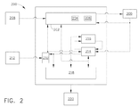
図2は、本発明の例示的な実施形態による、モデルベースエンジン制御システム200の概略ブロック図である。システム200は、プロセッサ204及びメモリユニット206を有することができる制御ロジック202を含む。制御ロジック202は、コマンド入力モジュール208に通信可能に結合され、該モジュールは、限定ではないが、パイロット、オートパイロット、フライバイワイヤ(fly−by−wire)システム、及び遠隔コマンドシステムなどの、複数のコマンド入力源からのコマンドを受け取るように構成される。制御ロジック202はまた、エンジン10上のアクチュエータ209に通信可能に結合される。制御ロジック202は、アクチュエータ209にモーションコマンドを送信し、該アクチュエータ209からアクチュエータ位置情報を受け取るように構成される。制御ロジック202はまた、入力信号処理モジュール210に通信可能に結合され、該処理モジュール210は、エンジン10上に位置付けられた、及びエンジン10外の他の場所に位置付けられた複数のセンサからセンサ値を受け取るように構成される。入力信号処理モジュール210は、センサ212の動作及び出力値を監視するように、且つエンジン10並びに他の監視されているシステム及び構成要素上の動作を最も正確に表すことができるセンサ212の組み合わせを選択するように構成される。例えば、エンジン10の運転パラメータは、複数のセンサによりモニタすることができる。複数のセンサの1つ又はそれ以上が機能せず、或いは異常な出力又は不正確と判断される出力を供給する場合には、入力信号処理モジュール210は、入力を生成するのに使用されるセンサの数が少ないために、動作パラメータの堅牢性が低下するという理由で、不良センサからの信号を無効にし、運転パラメータを監視している残りのセンサからの出力を再び組み合わせて制御ロジックに対する入力を提供することができるが、正確な出力を提供するセンサだけが入力を生成するのに使用されるので、この入力はより正確なものとなる。
FIG. 2 is a schematic block diagram of a model-based
エンジンモデル214は、ロータ速度、温度及び圧力などの感知されたパラメータを推定し、推進力、空気流、失速マージン、及びタービン入口温度などのパラメータを計算するのに使用される。計算されたパラメータは、例えば、限定ではないが、環境条件、出力設定パラメータ、及びエンジンモデル214に対するアクチュエータ位置入力に基づいている。例示的な実施形態において、エンジンモデル214は、物理ベースの空気熱力学モデルである。別の実施形態において、エンジンモデル214は、回帰フィットモデルである。
The
例示的な実施形態において、エンジンモデル214内の各構成部品(例えば、入口12、ファン組立体16、HPC20及び燃焼器22及びHPT24を含むコアガスタービンエンジン17、LPT26、並びにオーグメンタ28)が個々にモデル化され、次いで物理ベースのエンジンモデルのような特定のエンジンモデルに構築されるので、エンジンモデル214は、構成部品レベルモデル(Component Level Model(CLM))である。エンジンモデル214は、飛行条件、制御変数入力、及び高圧圧縮機抽気を考慮した高速過渡エンジンサイクルを提示するようプログラムされている。更に、エンジンモデル214は、エンジン構成部品の効率及び調整又は調節することができる流れなどのパラメータを含む。これらのパラメータは、パラメータ推定アルゴリズムを用いて修正し、これにより通常の又は平均的なエンジンのモデルを特定のエンジンのモデルに修正することができる。
In the exemplary embodiment, each component within engine model 214 (eg,
エンジンモデル214は、飛行条件、制御変数入力、及び高圧圧縮機抽気の影響を受けやすい。エンジンモデル214の品質パラメータは、主要な各回転構成部品についての流れ及び効率修正因子を含む。このような品質パラメータは、1つ又はそれ以上の入力に対する各構成部品の応答を定義する多項式の定数として具現化することができる。例示的な実施形態において、多項式定数は、テストデータを用いて導出される。テストデータは、定数が導出されるエンジンの環境要件及び適用要件を適正に表す運転中に測定される。或いは、テストデータは、エンジン10のシミュレーションから得られる排気温度を含むことができる。
The
ファン組立体16、圧縮機20、HPタービン24、及びLPタービン26の各々は、流れ修正因子及び効率修正因子を有する。パラメータの品質は、上述の感知されたエンジン構成部品パラメータに基づいている。これらの品質パラメータは、その公称値から調整されることにより、モデル計算に影響を与えることができる。これらの品質パラメータを適正に操作することにより、モデルは特定のエンジンの挙動をより正確にシミュレートし、エンジン毎の製造ばらつき、エンジン劣化、エンジン部品の損傷の影響を考慮することが可能になる。加えて、物理ベースのモデル10は、空気入口12、燃焼器22、及びバイパスダクト40に関連する構成要素及び感知パラメータを含む。
Each of
エンジンモデル214は、感知された場所に対応する運転パラメータと、同じ場所においてそれぞれ決定された運転パラメータとを比較するよう構成された追跡フィルタ216に通信可能に結合される。追跡フィルタ216は、構成部品の摩耗、構成部品効率、及び/又は構成部品故障の変化に関係なく、モデル214が連続的にエンジン10を確実に表現できるようにする。
The
正常性監視及び故障診断モジュール218は、モデル214及び追跡フィルタ216に通信可能に結合される。例示的な実施形態において、正常性監視及び故障診断モジュール218は、決定された運転パラメータ又は「仮想センサ」及びモデル214からのモデルパラメータに関するデータを受け取る。正常性監視及び故障診断モジュール218は、受信データに基づいた不良コード、勧告、及びメンテナンス命令220を発生する。
Health monitoring and
図3は、本発明の例示的な実施形態による、回帰ベースの例示的なモデル214の概略ブロック図である。例示的な実施形態において、モデル214は、センサ入力に基づく出力変数の変化を決定する回帰ベースモデルである。モデル214は、決定された出力値に直接関連する場合がある、或いは関連しない場合がある複数のデータポイントに対する曲線の当てはめを含む。曲線の当てはめを記述する、例えば多項式のような数学的関係はまた、それぞれの出力を決定するのにも使用される。多項式の係数のような数学的関係のパラメータは、「トレーニングデータ」を用いて得られる。トレーニングデータは、多数の事例を含み、各事例が、入力パラメータ(X)と、タービン温度のような関心のある少なくとも1つのパラメータ(Y)とを含む。トレーニングデータは、センサバイアス有及び無しで複数の運転条件で新しい及び劣化したエンジンを含むシミュレートしたエンジン(サイクルモデル)から得ることができる。実エンジンテストが後で回帰モデルにより計算されることになるパラメータを測定又は計算する手段を含む場合、トレーニングデータはまた、こうした実エンジンテストから得ることができる。例えば、テストエンジンは、LPタービン出口温度T5のようなタービン温度を測定するために、種々の円周方向及び半径方向位置に複数の熱電対を収容するレーキを備えることができる。こうしたレーキは、テストセルにおける測定には有効であるが、高コスト及び作動寿命が極めて短いことに起因して製品エンジン上での実施には好適ではない。
FIG. 3 is a schematic block diagram of an exemplary regression-based
例示的な実施形態において、モデル214は、複数のセンサS(1)、S(2)、・・・S(n)からのセンサ入力302を受け取る。モデル214は、回帰ベースアルゴリズム304、例えば、1つ又はそれ以上の出力306に対する出力を生成するために入力302の少なくとも1つに対応する多項式を含む。多の実施形態において、アルゴリズム304は、入力302に基づく出力306を記述する関数の組み合わせを含むことができる。回帰ベースモデル214は、例えば物理ベースモデルを設計するために因果関係が十分に理解されていない場合に、他のアルゴリズムよりもより有用とすることができる。
In the exemplary embodiment,
図4は、本発明の例示的な実施形態による物理ベースの推定器402を含む、例示的なガスタービンエンジンシステム400の概略ブロック図である。例示的な実施形態において、推定器402は、物理ベースモデルとして具現化され、エンジン10の物理的特性ベースのセンサ入力傾向偏差に基づく出力変数の変化を決定するモデル214を含む。場合によっては、エンジン10の物理的特性は、完全なモデルを生成するには不十分な場合がある。このような場合、エンジン10の物理的特性は、経験ベースのモデル部分が取って代わり、モデル214の精度を確保することができる。
FIG. 4 is a schematic block diagram of an exemplary gas
例示的な実施形態において、推定器402は、モデル214及び追跡フィルタ216を含む。推定器402は、未知のアクチュエータ位置バイアス値406によりバイアスされたエンジンアクチュエータ位置情報404と、公称エンジン品質情報408とを受け取る。エンジン10上に位置付けられたセンサからのエンジンセンサ出力値410と仮想センサ出力推定値412とが比較され、その差違がセンサ誤差416として追跡フィルタ216に送信される。センサ誤差416は、エンジン品質シフト推定値418及びアクチュエータバイアスシフト推定値420を生成するのに追跡フィルタ216によって使用される。エンジン品質シフト推定値418は、公称エンジン品質情報408と組み合わされ、モデル214に送信される。アクチュエータバイアスシフト推定値420は、アクチュエータシフト推定値426と組み合わされ、実エンジン品質推定値423を得て、モデル214に送信される。モデル214は、エンジン10上に設置された実センサにより直接測定されていない運転パラメータの仮想センサ出力を生成する。例示的な実施形態において、モデル214は、既知のセンサ出力をエンジン10の物理的特性の表現に関連付けて、過酷な環境にあることにより既知のセンサが耐え抜くことができない位置、又はセンサが故障した位置、或いはセンサの設置が非実際的もしくは高コストである位置で運転パラメータの出力を生成する。追跡フィルタ216は、センサ誤差信号416を用いて、モデル214の各項及びパラメータを調節し、センサ誤差416を低減する。調節は、例えば、限定ではないが、比例プラス積分制御ループ、Kalmanフィルタ、又はニューラルネットワークなどのパラメータ識別方式を用いて実施される。
In the exemplary embodiment,
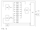
図5は、本発明の例示的な実施形態による、システム200(図2に示した)の一部の海略ブロック図である。例示的な実施形態において、システム200は、エンジン10上に位置付けられ、エンジン10に近接し、又はエンジン10から遠隔にある複数のセンサ500を含む。モデル214は、センサ出力に基づいて仮想センサの値を決定し、該センサ出力は、モデル214を通じて仮想センサ値に関連付ける。モデル214は、回帰ベースモデル、物理的ベースモデル、或いは、限定ではないが、マップモデル、ニューラルネットモデル、又は上記モデルの組み合わせなどの他のモデルとすることができる。
FIG. 5 is a schematic block diagram of a portion of system 200 (shown in FIG. 2), according to an illustrative embodiment of the invention. In the exemplary embodiment,
例示的な実施形態において、システム200は、10個のセンサを用いて、エンジン10(図1に示す)の運転パラメータ512を決定する。入力信号処理モジュール210は、センサ500の各々を監視し、適正な運転を検証する。10個のセンサ500の運転が適正である場合、システム200は、10個のセンサ500全て及びモデル502を用いて運転パラメータ512を決定する。モデル502は、回帰ベースモデル、物理ベースのモデル、或いは限定ではないが、マップモデル、ニューラルネットモデル、又は上述のモデルの組み合わせなどの他のモデルとすることができる。入力信号処理モジュール210がセンサ500の1つの故障を検出した場合、システム200は、センサ500の選択可能なサブセットを用いて運転パラメータ512を決定する。例えば、センサ500の第1のサブセット504は、センサ500の第2のサブセット506の冗長部とすることができ、センサ500及びモデル502、第1のサブセット504及びモデル505、及び/又は第2のサブセット506及びモデル507を用いて、運転パラメータ512を決定することができるようにする。例示的な実施形態において、第1のサブセット504は、第2のサブセット506の相互排他的なものであり、第1のサブセット504内のセンサ500の故障が第2のサブセット506及びそのそれぞれのモデル507により運転パラメータ512の決定に影響を与えないようにされ、その逆もまた同様である。デフォルトのモデル値508は、入力信号処理モジュール210が両方のサブセットにわたって複数のセンサ500での故障を検出する発生する可能性が低い事象においての運転パラメータ512で規定されている。選択モジュール210は、入力信号処理モジュール210からのセンサ故障に関する情報を用いて、モデル502、505、507の出力とデフォルト508とから選択する。10個のセンサ500全てを用いることにより、運転パラメータ512の決定がより堅牢にできると同時に、センサ500の複数のサブセットのうちの1つを交互に使用できることにより、この決定の信頼性をより高くすることができる。
In the exemplary embodiment,
図6は、エンジン10(図1に示す)の運転を制御する例示的な方法600のフロー図である。例示的な実施形態において、方法600は、エンジン上の対応する感知位置に関連する複数のセンサからのデータを受け取る段階602と、コンピュータ内に格納されてエンジンの運転をシミュレートするよう構成されたモデルに対して受け取ったデータを適用する段階604と、コンピュータモデルからの出力に基づいてエンジンの運転パラメータを決定する段階606とを含む。方法600はまた、決定された運転パラメータを該運転パラメータの所定の許容範囲に比較する段階608と、決定運転パラメータを所定許容範囲に戻すこと及び決定運転パラメータを所定許容範囲内に維持することの少なくとも1つを可能にするようエンジンの運転を制御し、決定運転パラメータをユーザに出力し、及び/又は比較に基づいてメンテナンス要求を生成する段階610を含む。
FIG. 6 is a flow diagram of an
当業者には理解されるように、物理ベース、経験ベース、ニューラルネットワークベース、及び回帰ベースのモデルが例証として本明細書で説明されたが、他のモデル化手法もまた、本発明の方法に従って使用するのに好適とすることができる。 As will be appreciated by those skilled in the art, physics-based, experience-based, neural network-based, and regression-based models have been described herein by way of example, but other modeling approaches are also in accordance with the method of the present invention. It can be suitable for use.
本明細書で使用する場合、プロセッサという用語は、中央処理装置、マイクロプロセッサ、マイクロコントローラ、縮小命令セット回路(RISC)、特定用途向け集積回路(ASIC)、ロジック回路、及び本明細書で説明した機能を実行できるあらゆる他の回路又はプロセッサを意味する。 As used herein, the term processor refers to a central processing unit, a microprocessor, a microcontroller, a reduced instruction set circuit (RISC), an application specific integrated circuit (ASIC), a logic circuit, and as described herein. Any other circuit or processor capable of performing the function.
本明細書で使用する場合、用語「ソフトウェア」及び「ファームウェア」は同義的であり、プロセッサ29によって実行するためメモリ内に格納されるあらゆるコンピュータプログラムを含む。メモリ206は、可変の、揮発性の、又は不揮発性のメモリ、或いは変更不能すなわち固定メモリのあらゆる適切な組み合わせを用いて実装することができる。可変メモリは、揮発性又は不揮発性であるかに関わらず、スタティック又はダイナミックRAM(Random Access Memory)、フロッピー(登録商標)ディスク及びハードドライブ、書き込み可能又は書き換え可能光学ディスク及びディスクドライブ、ハードディスク、及び/又はフラッシュメモリのうちのいずれか1つ又はそれ以上を用いて実装することができる。同様に、変更不能又は固定メモリは、ROM (Read−Only Memory)、PROM (Programmable Read−Only Memory)、EPROM (Erasable Programmable Read−Only Memory)、EEPROM (Electrically Erasable Programmable Read−Only Memory)、CD−ROM又はDVD−ROMディスクなどの光学ROMディスク、及び/又はディスクドライブのうちのいずれか1つ又はそれ以上を用いて実装することができる。上述のメモリタイプは、単なる例示的なものに過ぎず、従って、コンピュータプログラムの記憶装置に使用可能なメモリのタイプに関して限定するものではない。
As used herein, the terms “software” and “firmware” are synonymous and include any computer program stored in memory for execution by the processor 29. The
以上の明細書に基づいて理解されるように、本開示の上述の実施形態は、コンピュータソフトウェア、ファームウェア、或いはそのあらゆる組み合わせ又はサブセットを含むコンピュータプログラム又はエンジニアリング技術を使用して実装することができ、この技術的作用は、制御システムが既に利用可能な他の測定変数に基づいて、例えば燃焼器の下流側の関心のある運転パラメータをコンピュータモデルを用いて計算することである。これらの測定変数は、例えば燃焼器の上流側のアクチュエータ位置、ロータ速度、ガス通路圧力、及び温度測定値を含む。モデルは、回帰ベース又は物理ベースとすることができる。更に、温度は、HPTブレード、HPTノズル、LPTブレード、又はLPTノズル上の特定の位置など複数の位置で計算され、エンジン制御システムにおける最も限定的なパラメータを用いる。本方法は、タービン温度測定値を必要とせず、ガス通路平均又はメタル温度を提供し、温度遅延を受けず、制御運転を最も限定的なパラメータに適応的に制限する能力を提供する。コンピュータ読取り可能コード手段を有するこのような結果として得られるあらゆるプログラムは、1つ又はそれ以上のコンピュータ読取り可能媒体内で具現化され又は提供され、これにより本開示の検討された実施形態による、コンピュータプログラム製品すなわち製造物品を形成することができる。コンピュータ読取り可能媒体は、例えば、限定ではないが、固定(ハード)ドライブ、ディスケット、光学ディスク、磁気テープ、読取り専用メモリ(ROM)のような半導体メモリ、及び/又はインターネット或いは他の通信ネットワークもしくはリンクのようなあらゆる送信/受信媒体とすることができる。コンピュータコードを含む製造物品は、1つの媒体からコードを直接実行することによって、又は1つの媒体から他の媒体にコードをコピーすることによって、或いはネットワーク上でコードを送信することによって実施及び/又は利用することができる。 As will be understood based on the foregoing specification, the above-described embodiments of the present disclosure may be implemented using a computer program, engineering technology, including computer software, firmware, or any combination or subset thereof, The technical action is to calculate the operating parameters of interest, for example downstream of the combustor, using a computer model, based on other measurement variables already available to the control system. These measurement variables include, for example, actuator position upstream of the combustor, rotor speed, gas path pressure, and temperature measurements. The model can be regression based or physical based. In addition, the temperature is calculated at multiple locations, such as HPT blades, HPT nozzles, LPT blades, or specific locations on the LPT nozzles, and uses the most restrictive parameters in the engine control system. The method does not require turbine temperature measurements, provides gas path average or metal temperature, is not subject to temperature delays, and provides the ability to adaptively limit control operations to the most restrictive parameters. Any such resulting program having computer readable code means may be embodied or provided in one or more computer readable media, thereby providing a computer according to the contemplated embodiments of the present disclosure. A program product or manufactured article can be formed. The computer readable medium can be, for example but not limited to, a fixed (hard) drive, a diskette, an optical disk, a magnetic tape, a semiconductor memory such as a read only memory (ROM), and / or the Internet or other communication network or link. Any transmission / reception medium can be used. Articles of manufacture containing computer code can be implemented and / or by executing code directly from one medium, by copying code from one medium to another, or by transmitting the code over a network Can be used.
例えば限定ではないがガスタービンエンジンのような機械の温度などの運転パラメータを制御する方法及びシステムの上記の実施形態は、機械の実センサ出力に基づいて仮想センサ出力を決定する、コスト効果があり且つ信頼性のある手段を提供する。より具体的には、本明細書で記載された本方法及びシステムは、運転パラメータを決定するのに使用されるセンサの冗長性を管理可能にする。加えて、上述の方法及びシステムは、運転パラメータを許容限度内に維持する及び/又は運転パラメータを許容限度に戻すように機械運転の変更に影響を与えるアクチュエータ制御信号を出力することができる。結果として、本明細書で記載された本方法及びシステムは、コスト効果があり且つ信頼性のある手法で機械運転を制御可能にする。 The above embodiments of methods and systems for controlling operating parameters such as, for example, but not limited to the temperature of a machine such as a gas turbine engine, are cost effective in determining virtual sensor output based on the actual sensor output of the machine. And provide a reliable means. More specifically, the methods and systems described herein allow for managing the redundancy of sensors used to determine operating parameters. In addition, the methods and systems described above can output actuator control signals that affect changes in machine operation to maintain operating parameters within acceptable limits and / or return operational parameters to acceptable limits. As a result, the methods and systems described herein allow machine operation to be controlled in a cost-effective and reliable manner.
以上で、センサによって直接監視されない機械領域における機械の運転パラメータを自動的に連続して決定する例示的な方法及びシステムが詳細に説明された。例示のシステムは、本明細書で説明した特定の実施形態に限定されるものでなく、むしろ、各々の構成部品は、本明細書で説明した他の構成部品から独立して別個に利用することができる。各システム構成部品はまた、他のシステム構成部品と組み合わせて使用することもできる。 The foregoing has described in detail an exemplary method and system for automatically and continuously determining machine operating parameters in a machine area not directly monitored by sensors. The exemplary system is not limited to the specific embodiments described herein, but rather each component is utilized separately and independently of the other components described herein. Can do. Each system component can also be used in combination with other system components.
本発明を種々の特定の実施形態について説明してきたが、本発明は請求項の精神及び範囲内にある変更形態で実施可能である点は当業者であれば理解されるであろう。 While the invention has been described in terms of various specific embodiments, those skilled in the art will recognize that the invention can be practiced with modification within the spirit and scope of the claims.
200 エンジンコントローラシステム
202 制御ロジック
204 プロセッサ
206 メモリユニット
208 コマンド入力モジュール
209 アクチュエータ
210 入力信号処理モジュール
212 センサ
214 エンジンモデル
216 追跡フィルタ
218 正常性監視及び故障診断モジュール
220 メンテナンス要求
200
Claims (10)
プロセッサ(204)と、
を備えたエンジンコントローラシステム(200)であって、
前記プロセッサ(204)が、
前記決定運転パラメータ値を前記運転パラメータの所定許容範囲に比較(608)し、
前記決定運転パラメータを前記所定許容範囲に戻すこと及び前記決定運転パラメータを前記所定許容範囲内に維持することの少なくとも1つを可能にするよう前記エンジンの運転を制御(610)し、前記決定運転パラメータ値をユーザに出力し、及び前記比較に基づいてメンテナンス要求(220)を生成することのうちの少なくとも1つを行う、
ように構成されている、
エンジンコントローラシステム(200)。 An engine model (214) programmed to receive engine operating state values from a plurality of sensors (500) positioned on the engine (10) and determine a plurality of engine operating parameter values (512);
A processor (204);
An engine controller system (200) comprising:
The processor (204)
Comparing the determined operating parameter value to a predetermined allowable range of the operating parameter (608);
Controlling the operation of the engine to allow at least one of returning the determined operating parameter to the predetermined allowable range and maintaining the determined operating parameter within the predetermined allowable range; Performing at least one of outputting a parameter value to the user and generating a maintenance request (220) based on the comparison;
Configured as
Engine controller system (200).
請求項1に記載のエンジンコントローラシステム(200)。 The processor (204) is further configured to update a parameter of the model (214) representing the normality of the gas turbine engine (10).
The engine controller system (200) of claim 1.
請求項1または2に記載のエンジンコントローラシステム(200)。 The model (214) includes a polynomial for each of the determined operating parameter values (512);
Engine controller system (200) according to claim 1 or 2.
請求項1乃至3のいずれか1項に記載のエンジンコントローラシステム(200)。 At least one of the plurality of engine operating parameter values (512) is output from a set of sensors (500) associated with the operating parameters using the model (214), a first subset (504) of the set of sensors ) And a second subset (506) of the set of mutually exclusive sensors of the first subset,
The engine controller system (200) according to any one of the preceding claims.
プロセッサユニット(204)と、
を備えたガスタービンエンジン(10)の運転を制御するためのシステム(200)であって、
前記プロセッサユニットが、
前記決定運転パラメータ値を前記運転パラメータの所定許容範囲に比較(608)し、
前記決定運転パラメータを前記所定許容範囲に戻すこと及び前記決定運転パラメータを前記所定許容範囲内に維持することの少なくとも1つを可能にするよう前記エンジンの運転を制御(610)し、前記決定運転パラメータ値をユーザに出力し、及び前記比較に基づいてメンテナンス要求(220)を生成することのうちの少なくとも1つを行う、
ようにプログラムされている、
システム(200)。 An engine model (214) having at least one input for receiving engine operating conditions and configured to determine a plurality of gas turbine engine operating parameter values (512);
A processor unit (204);
A system (200) for controlling operation of a gas turbine engine (10) comprising:
The processor unit is
Comparing the determined operating parameter value to a predetermined allowable range of the operating parameter (608);
Controlling the operation of the engine to allow at least one of returning the determined operating parameter to the predetermined allowable range and maintaining the determined operating parameter within the predetermined allowable range; Performing at least one of outputting a parameter value to the user and generating a maintenance request (220) based on the comparison;
Is programmed to,
System (200).
請求項5に記載のシステム(200)。 The processor (204) is further configured to update a parameter of the model (214) representing the normality of the gas turbine engine (10).
The system (200) of claim 5.
請求項5または6に記載のシステム(200)。 The model (214) includes a polynomial for each of the determined operating parameter values (512);
System (200) according to claim 5 or 6.
請求項5乃至7のいずれか1項に記載のシステム(200)。 At least one of the plurality of engine operating parameter values (512) is a gas turbine engine operating parameter corresponding to a position on the engine (10) where at least one of the sensors is not present or the sensor located there is defective. Including value,
A system (200) according to any one of claims 5 to 7.
請求項5乃至7のいずれか1項に記載のシステム(200)。 At least one of the plurality of engine operating parameter values (512) is determined using an output from a set of sensors (500) associated with the operating parameters using the model (214);
A system (200) according to any one of claims 5 to 7.
請求項9に記載のシステム(200)。 At least one of the plurality of engine operating parameter values (512) is determined using a first subset (504) of the set of sensors (500);
The system (200) of claim 9.
Applications Claiming Priority (2)
| Application Number | Priority Date | Filing Date | Title |
|---|---|---|---|
| US12/181,079 | 2008-07-28 | ||
| US12/181,079 US8478473B2 (en) | 2008-07-28 | 2008-07-28 | Method and systems for controlling gas turbine engine temperature |
Publications (2)
| Publication Number | Publication Date |
|---|---|
| JP2010031841A true JP2010031841A (en) | 2010-02-12 |
| JP5554942B2 JP5554942B2 (en) | 2014-07-23 |
Family
ID=40887199
Family Applications (1)
| Application Number | Title | Priority Date | Filing Date |
|---|---|---|---|
| JP2009125981A Expired - Fee Related JP5554942B2 (en) | 2008-07-28 | 2009-05-26 | Method and system for controlling gas turbine engine temperature |
Country Status (4)
| Country | Link |
|---|---|
| US (1) | US8478473B2 (en) |
| EP (1) | EP2149832A3 (en) |
| JP (1) | JP5554942B2 (en) |
| CA (1) | CA2666455C (en) |
Cited By (8)
| Publication number | Priority date | Publication date | Assignee | Title |
|---|---|---|---|---|
| JP2012242159A (en) * | 2011-05-17 | 2012-12-10 | Internatl Business Mach Corp <Ibm> | Method for interpolating sensor data for high availability of system, computer program and system |
| JP2014213853A (en) * | 2013-04-23 | 2014-11-17 | ザ・ボーイング・カンパニーTheBoeing Company | Aircraft performance monitoring system |
| JP2017141819A (en) * | 2016-02-02 | 2017-08-17 | ゼネラル・エレクトリック・カンパニイ | Controlling gas turbine engine considering airflow distortion |
| JP2017180457A (en) * | 2016-03-30 | 2017-10-05 | ゼネラル・エレクトリック・カンパニイ | Secondary airflow passage for adjusting airflow distortion in gas turbine engine |
| CN107842426A (en) * | 2016-09-20 | 2018-03-27 | 通用电气公司 | Intelligent liquid fuel system with self diagnostic capability |
| US10753278B2 (en) | 2016-03-30 | 2020-08-25 | General Electric Company | Translating inlet for adjusting airflow distortion in gas turbine engine |
| US10794281B2 (en) | 2016-02-02 | 2020-10-06 | General Electric Company | Gas turbine engine having instrumented airflow path components |
| US11073090B2 (en) | 2016-03-30 | 2021-07-27 | General Electric Company | Valved airflow passage assembly for adjusting airflow distortion in gas turbine engine |
Families Citing this family (22)
| Publication number | Priority date | Publication date | Assignee | Title |
|---|---|---|---|---|
| US7861578B2 (en) * | 2008-07-29 | 2011-01-04 | General Electric Company | Methods and systems for estimating operating parameters of an engine |
| FR2939508B1 (en) * | 2008-12-09 | 2011-01-07 | Snecma | METHOD AND SYSTEM FOR CORRECTING MEASUREMENT SIGNAL OF TEMPERATURE. |
| US8862433B2 (en) * | 2010-05-18 | 2014-10-14 | United Technologies Corporation | Partitioning of turbomachine faults |
| DE102010035825A1 (en) * | 2010-08-30 | 2012-03-01 | Liebherr-Aerospace Lindenberg Gmbh | Control system and apparatus for generating a virtual real-time model |
| US20120283849A1 (en) * | 2011-05-06 | 2012-11-08 | Kureemun Ridwan | Sensor system having time lag compensation |
| US20130024179A1 (en) * | 2011-07-22 | 2013-01-24 | General Electric Company | Model-based approach for personalized equipment degradation forecasting |
| CA2805286C (en) * | 2012-02-20 | 2016-04-05 | Alstom Technology Ltd. | Control system to monitor and control a turbine |
| US8490404B1 (en) * | 2012-02-28 | 2013-07-23 | General Electric Company | Sensor-based performance-seeking gas turbine engine control |
| US20140161612A1 (en) * | 2012-12-07 | 2014-06-12 | General Electric Company | Tip shroud monitoring system, method, and controller |
| WO2014143887A2 (en) * | 2013-03-15 | 2014-09-18 | United Technologies Corporation | Compact aero-thermo model based engine power control |
| GB2514108B (en) * | 2013-05-13 | 2015-06-24 | Ge Aviat Systems Ltd | Method for diagnosing a bleed air system fault |
| US20150075170A1 (en) * | 2013-09-17 | 2015-03-19 | General Electric Company | Method and system for augmenting the detection reliability of secondary flame detectors in a gas turbine |
| US9696217B2 (en) | 2013-10-30 | 2017-07-04 | United Technologies Corporation | Phosphor thermometer with two waveguides |
| US10459885B2 (en) * | 2014-04-11 | 2019-10-29 | United Technologies Corporation | Portable memory device data modeling for effective processing for a gas turbine engine |
| US20170138781A1 (en) * | 2015-11-17 | 2017-05-18 | General Electric Company | Method and system for improving parameter measurement |
| US10604278B2 (en) * | 2017-04-18 | 2020-03-31 | General Electric Company | Methods and apparatus to monitor health information of a turbine engine |
| US20180306054A1 (en) * | 2017-04-20 | 2018-10-25 | General Electric Company | Compressor water-wash advisory |
| US11193387B2 (en) * | 2017-07-11 | 2021-12-07 | General Electric Company | Performance and life optimizing control system for a turbine engine |
| US11268449B2 (en) * | 2017-09-22 | 2022-03-08 | General Electric Company | Contamination accumulation modeling |
| US11067592B2 (en) * | 2017-11-10 | 2021-07-20 | General Electric Company | Methods and apparatus for prognostic health monitoring of a turbine engine |
| US11300069B2 (en) * | 2018-11-28 | 2022-04-12 | Honeywell International Inc. | Self-generating engine-specific health monitoring model from generic model base |
| US20200248622A1 (en) * | 2019-02-01 | 2020-08-06 | United Technologies Corporation | Machine learned aero-thermodynamic engine inlet condition synthesis |
Citations (11)
| Publication number | Priority date | Publication date | Assignee | Title |
|---|---|---|---|---|
| JPH03138425A (en) * | 1989-10-25 | 1991-06-12 | Toshiba Corp | Gas turbine temperature protector |
| JPH03156129A (en) * | 1989-11-13 | 1991-07-04 | Nissan Motor Co Ltd | Turbine inlet port temperature detecting device for gas turbine with heat exchanger |
| JPH10293049A (en) * | 1997-04-16 | 1998-11-04 | Toshiba Corp | Maintenance control method and device for gas turbine |
| US20040000144A1 (en) * | 2002-06-26 | 2004-01-01 | Ravi Rajamani | Gas turbine system operation based on estimated stress |
| JP2004019576A (en) * | 2002-06-18 | 2004-01-22 | Ishikawajima Harima Heavy Ind Co Ltd | Control device of cogeneration plant |
| JP2004027848A (en) * | 2002-05-20 | 2004-01-29 | Toshiba Corp | Gas turbine controller |
| JP2004162698A (en) * | 2002-11-13 | 2004-06-10 | General Electric Co <Ge> | Adaptation control system for model base for controlling gas turbine |
| JP2005171789A (en) * | 2003-12-09 | 2005-06-30 | General Electric Co <Ge> | Method and device for model prediction control of gas turbine for aircraft |
| JP2005248946A (en) * | 2004-03-02 | 2005-09-15 | General Electric Co <Ge> | Model-based control system and method for gas turbine engine |
| JP2006220151A (en) * | 2005-02-10 | 2006-08-24 | General Electric Co <Ge> | Method for optimizing combined cycle/combined process facility |
| JP2008088961A (en) * | 2006-10-05 | 2008-04-17 | Hitachi Ltd | Gas turbine performance diagnostic system and diagnostic method, and display screen |
Family Cites Families (35)
| Publication number | Priority date | Publication date | Assignee | Title |
|---|---|---|---|---|
| US4039804A (en) | 1972-03-14 | 1977-08-02 | Westinghouse Electric Corporation | System and method for monitoring industrial gas turbine operating parameters and for providing gas turbine power plant control system inputs representative thereof |
| US4259835A (en) | 1978-02-06 | 1981-04-07 | Westinghouse Electric Corp. | System and method for monitoring industrial gas turbine operating parameters and for providing gas turbine power plant control system inputs representative thereof |
| JPS6011657A (en) | 1983-06-30 | 1985-01-21 | Honda Motor Co Ltd | Abnormality detector for measuring system of operational parameter sensor of internal-combustion engine |
| US5539638A (en) * | 1993-08-05 | 1996-07-23 | Pavilion Technologies, Inc. | Virtual emissions monitor for automobile |
| US5832421A (en) * | 1996-12-13 | 1998-11-03 | Siemens Corporate Research, Inc. | Method for blade temperature estimation in a steam turbine |
| DE19739901B4 (en) | 1997-09-11 | 2008-04-17 | Robert Bosch Gmbh | Method and device for controlling an internal combustion engine depending on operating parameters |
| US6076510A (en) | 1998-05-22 | 2000-06-20 | Hyundai Motor Co. | Method and apparatus for correcting air-flow sensor output and adapting data map used to control engine operating parameters |
| US6539783B1 (en) * | 1998-12-28 | 2003-04-01 | General Electric Co. | Methods and apparatus for estimating engine health |
| SE523336C2 (en) | 1999-04-19 | 2004-04-13 | Volvo Personvagnar Ab | Procedure and arrangement for limiting controllable operating parameters in a motor |
| US6092016A (en) * | 1999-01-25 | 2000-07-18 | Caterpillar, Inc. | Apparatus and method for diagnosing an engine using an exhaust temperature model |
| US6463380B1 (en) * | 1999-06-01 | 2002-10-08 | General Electric Company | Control system and method for controlling an engine in response to deterioration of the engine |
| US7020595B1 (en) * | 1999-11-26 | 2006-03-28 | General Electric Company | Methods and apparatus for model based diagnostics |
| US6502085B1 (en) * | 1999-12-18 | 2002-12-31 | General Electric Company | Methods and systems for estimating engine faults |
| US6598195B1 (en) * | 2000-08-21 | 2003-07-22 | General Electric Company | Sensor fault detection, isolation and accommodation |
| US6466858B1 (en) * | 2000-11-02 | 2002-10-15 | General Electric Company | Methods and apparatus for monitoring gas turbine engine operation |
| ATE544106T1 (en) * | 2001-02-19 | 2012-02-15 | Abb Schweiz Ag | DETERMINATION OF DEGRADATION OF A GAS TURBINE |
| US6804601B2 (en) * | 2002-03-19 | 2004-10-12 | Cummins, Inc. | Sensor failure accommodation system |
| US7219040B2 (en) * | 2002-11-05 | 2007-05-15 | General Electric Company | Method and system for model based control of heavy duty gas turbine |
| JP3760911B2 (en) * | 2002-11-27 | 2006-03-29 | トヨタ自動車株式会社 | Model creation method, model creation program, and simulation apparatus |
| US6873902B2 (en) | 2003-03-27 | 2005-03-29 | Snap-On Incorporated | Non-intrusive method of measuring engine operating parameters |
| US7032388B2 (en) * | 2003-11-17 | 2006-04-25 | General Electric Company | Method and system for incorporating an emission sensor into a gas turbine controller |
| US7305825B2 (en) | 2004-10-14 | 2007-12-11 | General Motors Corporation | Engine turbine temperature control system |
| US7356371B2 (en) * | 2005-02-11 | 2008-04-08 | Alstom Technology Ltd | Adaptive sensor model |
| US7693643B2 (en) * | 2005-02-14 | 2010-04-06 | Honeywell International Inc. | Fault detection system and method for turbine engine fuel systems |
| US7379799B2 (en) | 2005-06-29 | 2008-05-27 | General Electric Company | Method and system for hierarchical fault classification and diagnosis in large systems |
| JP4172594B2 (en) | 2005-08-25 | 2008-10-29 | 本田技研工業株式会社 | Temperature sensor failure determination device |
| US7742904B2 (en) * | 2005-09-27 | 2010-06-22 | General Electric Company | Method and system for gas turbine engine simulation using adaptive Kalman filter |
| US7603222B2 (en) * | 2005-11-18 | 2009-10-13 | General Electric Company | Sensor diagnostics using embedded model quality parameters |
| US7505844B2 (en) * | 2005-11-18 | 2009-03-17 | General Electric Company | Model-based iterative estimation of gas turbine engine component qualities |
| US7483774B2 (en) * | 2006-12-21 | 2009-01-27 | Caterpillar Inc. | Method and system for intelligent maintenance |
| US7813869B2 (en) * | 2007-03-30 | 2010-10-12 | Caterpillar Inc | Prediction based engine control system and method |
| US7908072B2 (en) * | 2007-06-26 | 2011-03-15 | General Electric Company | Systems and methods for using a combustion dynamics tuning algorithm with a multi-can combustor |
| US7748217B2 (en) * | 2007-10-04 | 2010-07-06 | Delphi Technologies, Inc. | System and method for modeling of turbo-charged engines and indirect measurement of turbine and waste-gate flow and turbine efficiency |
| US7861578B2 (en) * | 2008-07-29 | 2011-01-04 | General Electric Company | Methods and systems for estimating operating parameters of an engine |
| US8364340B2 (en) * | 2009-03-31 | 2013-01-29 | General Electric Company | Method and systems for virtual sensor selection and blending |
-
2008
- 2008-07-28 US US12/181,079 patent/US8478473B2/en active Active
-
2009
- 2009-05-19 EP EP09160673.1A patent/EP2149832A3/en not_active Ceased
- 2009-05-21 CA CA2666455A patent/CA2666455C/en not_active Expired - Fee Related
- 2009-05-26 JP JP2009125981A patent/JP5554942B2/en not_active Expired - Fee Related
Patent Citations (11)
| Publication number | Priority date | Publication date | Assignee | Title |
|---|---|---|---|---|
| JPH03138425A (en) * | 1989-10-25 | 1991-06-12 | Toshiba Corp | Gas turbine temperature protector |
| JPH03156129A (en) * | 1989-11-13 | 1991-07-04 | Nissan Motor Co Ltd | Turbine inlet port temperature detecting device for gas turbine with heat exchanger |
| JPH10293049A (en) * | 1997-04-16 | 1998-11-04 | Toshiba Corp | Maintenance control method and device for gas turbine |
| JP2004027848A (en) * | 2002-05-20 | 2004-01-29 | Toshiba Corp | Gas turbine controller |
| JP2004019576A (en) * | 2002-06-18 | 2004-01-22 | Ishikawajima Harima Heavy Ind Co Ltd | Control device of cogeneration plant |
| US20040000144A1 (en) * | 2002-06-26 | 2004-01-01 | Ravi Rajamani | Gas turbine system operation based on estimated stress |
| JP2004162698A (en) * | 2002-11-13 | 2004-06-10 | General Electric Co <Ge> | Adaptation control system for model base for controlling gas turbine |
| JP2005171789A (en) * | 2003-12-09 | 2005-06-30 | General Electric Co <Ge> | Method and device for model prediction control of gas turbine for aircraft |
| JP2005248946A (en) * | 2004-03-02 | 2005-09-15 | General Electric Co <Ge> | Model-based control system and method for gas turbine engine |
| JP2006220151A (en) * | 2005-02-10 | 2006-08-24 | General Electric Co <Ge> | Method for optimizing combined cycle/combined process facility |
| JP2008088961A (en) * | 2006-10-05 | 2008-04-17 | Hitachi Ltd | Gas turbine performance diagnostic system and diagnostic method, and display screen |
Cited By (11)
| Publication number | Priority date | Publication date | Assignee | Title |
|---|---|---|---|---|
| JP2012242159A (en) * | 2011-05-17 | 2012-12-10 | Internatl Business Mach Corp <Ibm> | Method for interpolating sensor data for high availability of system, computer program and system |
| JP2014213853A (en) * | 2013-04-23 | 2014-11-17 | ザ・ボーイング・カンパニーTheBoeing Company | Aircraft performance monitoring system |
| JP2017141819A (en) * | 2016-02-02 | 2017-08-17 | ゼネラル・エレクトリック・カンパニイ | Controlling gas turbine engine considering airflow distortion |
| US10794281B2 (en) | 2016-02-02 | 2020-10-06 | General Electric Company | Gas turbine engine having instrumented airflow path components |
| JP2017180457A (en) * | 2016-03-30 | 2017-10-05 | ゼネラル・エレクトリック・カンパニイ | Secondary airflow passage for adjusting airflow distortion in gas turbine engine |
| US10753278B2 (en) | 2016-03-30 | 2020-08-25 | General Electric Company | Translating inlet for adjusting airflow distortion in gas turbine engine |
| US11073090B2 (en) | 2016-03-30 | 2021-07-27 | General Electric Company | Valved airflow passage assembly for adjusting airflow distortion in gas turbine engine |
| US11448127B2 (en) | 2016-03-30 | 2022-09-20 | General Electric Company | Translating inlet for adjusting airflow distortion in gas turbine engine |
| CN107842426A (en) * | 2016-09-20 | 2018-03-27 | 通用电气公司 | Intelligent liquid fuel system with self diagnostic capability |
| JP2018048628A (en) * | 2016-09-20 | 2018-03-29 | ゼネラル・エレクトリック・カンパニイ | Smart liquid fuel system with ability to self-diagnostics |
| JP7019352B2 (en) | 2016-09-20 | 2022-02-15 | ゼネラル・エレクトリック・カンパニイ | Smart liquid fuel system with self-diagnosis capability |
Also Published As
| Publication number | Publication date |
|---|---|
| EP2149832A2 (en) | 2010-02-03 |
| CA2666455C (en) | 2016-07-05 |
| JP5554942B2 (en) | 2014-07-23 |
| US8478473B2 (en) | 2013-07-02 |
| US20100023238A1 (en) | 2010-01-28 |
| EP2149832A3 (en) | 2014-08-27 |
| CA2666455A1 (en) | 2010-01-28 |
Similar Documents
| Publication | Publication Date | Title |
|---|---|---|
| JP5554942B2 (en) | Method and system for controlling gas turbine engine temperature | |
| US8364340B2 (en) | Method and systems for virtual sensor selection and blending | |
| JP5318662B2 (en) | Method and system for estimating operating parameters of an engine | |
| JP2007138937A (en) | Gas turbine engine control system using quality parameters | |
| EP3239500B1 (en) | Control of machinery with calibrated performance model | |
| EP3081787B1 (en) | Application of probabilistic control in gas turbine tuning for fuel flow-emissions parameters, related control systems and computer porgram | |
| US9599032B2 (en) | Application of probabilistic control in gas turbine tuning for emissions-fuel flow parameters, related control systems, computer program products and methods | |
| US9611791B2 (en) | Application of probabilistic control in gas turbine tuning for fuel flow-power output parameters, related control systems, computer program products and methods | |
| JP6640534B2 (en) | Control system, computer program product, and method associated with application of fuel flow based stochastic control in gas turbine tuning under partial load | |
| US9797315B2 (en) | Probabilistic control in gas turbine tuning for power output-emissions parameters, related control systems, computer program products and methods | |
| US9803561B2 (en) | Power output and emissions based degraded gas turbine tuning and control systems, computer program products and related methods | |
| US9599033B2 (en) | Application of probabilistic control in gas turbine tuning for fuel flow-exhaust energy parameters, related control systems, computer program products and methods | |
| US9599025B2 (en) | Application of probabilistic control in gas turbine tuning for power output-exhaust energy parameters, related control systems, computer program products and methods | |
| US9599026B2 (en) | Application of probabilistic control in gas turbine tuning for exhaust energy-power output parameters, related control systems, computer program products and methods | |
| US9771875B2 (en) | Application of probabilistic control in gas turbine tuning, related control systems, computer program products and methods | |
| EP3081786B1 (en) | Application of probabilistic control in gas turbine tuning for exhaust energy-emissions parameters, related control systems and computer porgram. | |
| US9599027B2 (en) | Application of probabilistic control in gas turbine tuning for emissions-exhaust energy parameters, related control systems, computer program products and methods | |
| US9599030B2 (en) | Application of probabilistic control in gas turbine tuning for exhaust energy-fuel flow parameters, related control systems, computer program products and methods | |
| JP6666122B2 (en) | Control system, computer program product, and method related to applying stochastic control in gas turbine tuning in response to measurement error | |
| US9771874B2 (en) | Power output and fuel flow based probabilistic control in gas turbine tuning, related control systems, computer program products and methods |
Legal Events
| Date | Code | Title | Description |
|---|---|---|---|
| A621 | Written request for application examination |
Free format text: JAPANESE INTERMEDIATE CODE: A621 Effective date: 20120515 |
|
| A977 | Report on retrieval |
Free format text: JAPANESE INTERMEDIATE CODE: A971007 Effective date: 20130529 |
|
| A601 | Written request for extension of time |
Free format text: JAPANESE INTERMEDIATE CODE: A601 Effective date: 20130910 |
|
| A602 | Written permission of extension of time |
Free format text: JAPANESE INTERMEDIATE CODE: A602 Effective date: 20130913 |
|
| A521 | Request for written amendment filed |
Free format text: JAPANESE INTERMEDIATE CODE: A523 Effective date: 20131210 |
|
| TRDD | Decision of grant or rejection written | ||
| A01 | Written decision to grant a patent or to grant a registration (utility model) |
Free format text: JAPANESE INTERMEDIATE CODE: A01 Effective date: 20140513 |
|
| A61 | First payment of annual fees (during grant procedure) |
Free format text: JAPANESE INTERMEDIATE CODE: A61 Effective date: 20140530 |
|
| R150 | Certificate of patent or registration of utility model |
Ref document number: 5554942 Country of ref document: JP Free format text: JAPANESE INTERMEDIATE CODE: R150 |
|
| R250 | Receipt of annual fees |
Free format text: JAPANESE INTERMEDIATE CODE: R250 |
|
| LAPS | Cancellation because of no payment of annual fees |