JP2010029828A - Agitator - Google Patents
Agitator Download PDFInfo
- Publication number
- JP2010029828A JP2010029828A JP2008197391A JP2008197391A JP2010029828A JP 2010029828 A JP2010029828 A JP 2010029828A JP 2008197391 A JP2008197391 A JP 2008197391A JP 2008197391 A JP2008197391 A JP 2008197391A JP 2010029828 A JP2010029828 A JP 2010029828A
- Authority
- JP
- Japan
- Prior art keywords
- main shaft
- arm
- stirring blade
- stirrer
- reinforced plastic
- Prior art date
- Legal status (The legal status is an assumption and is not a legal conclusion. Google has not performed a legal analysis and makes no representation as to the accuracy of the status listed.)
- Granted
Links
- 229920000049 Carbon (fiber) Polymers 0.000 claims abstract description 33
- 239000004917 carbon fiber Substances 0.000 claims abstract description 33
- 239000011152 fibreglass Substances 0.000 claims abstract description 28
- VNWKTOKETHGBQD-UHFFFAOYSA-N methane Chemical compound C VNWKTOKETHGBQD-UHFFFAOYSA-N 0.000 claims abstract description 28
- XLYOFNOQVPJJNP-UHFFFAOYSA-N water Substances O XLYOFNOQVPJJNP-UHFFFAOYSA-N 0.000 claims abstract description 11
- 239000000835 fiber Substances 0.000 claims abstract description 10
- 239000012779 reinforcing material Substances 0.000 claims abstract description 5
- 238000003756 stirring Methods 0.000 claims description 39
- 238000012423 maintenance Methods 0.000 abstract description 7
- 238000013019 agitation Methods 0.000 abstract 2
- XEEYBQQBJWHFJM-UHFFFAOYSA-N Iron Chemical compound [Fe] XEEYBQQBJWHFJM-UHFFFAOYSA-N 0.000 description 26
- 229910052742 iron Inorganic materials 0.000 description 13
- 229910001220 stainless steel Inorganic materials 0.000 description 11
- 239000010935 stainless steel Substances 0.000 description 11
- 239000000463 material Substances 0.000 description 10
- 238000009434 installation Methods 0.000 description 9
- 239000002023 wood Substances 0.000 description 8
- 238000005452 bending Methods 0.000 description 5
- 230000007797 corrosion Effects 0.000 description 5
- 238000005260 corrosion Methods 0.000 description 5
- 230000005484 gravity Effects 0.000 description 4
- 230000008878 coupling Effects 0.000 description 3
- 238000010168 coupling process Methods 0.000 description 3
- 238000005859 coupling reaction Methods 0.000 description 3
- JEIPFZHSYJVQDO-UHFFFAOYSA-N iron(III) oxide Inorganic materials O=[Fe]O[Fe]=O JEIPFZHSYJVQDO-UHFFFAOYSA-N 0.000 description 3
- 239000007800 oxidant agent Substances 0.000 description 3
- 239000003973 paint Substances 0.000 description 3
- 230000003014 reinforcing effect Effects 0.000 description 3
- 239000000126 substance Substances 0.000 description 3
- 239000003795 chemical substances by application Substances 0.000 description 2
- 239000008394 flocculating agent Substances 0.000 description 2
- 239000003365 glass fiber Substances 0.000 description 2
- 238000004519 manufacturing process Methods 0.000 description 2
- 239000003206 sterilizing agent Substances 0.000 description 2
- OKTJSMMVPCPJKN-UHFFFAOYSA-N Carbon Chemical compound [C] OKTJSMMVPCPJKN-UHFFFAOYSA-N 0.000 description 1
- 229910000831 Steel Inorganic materials 0.000 description 1
- 230000004931 aggregating effect Effects 0.000 description 1
- XAGFODPZIPBFFR-UHFFFAOYSA-N aluminium Chemical compound [Al] XAGFODPZIPBFFR-UHFFFAOYSA-N 0.000 description 1
- 229910052782 aluminium Inorganic materials 0.000 description 1
- 229910052799 carbon Inorganic materials 0.000 description 1
- 239000011248 coating agent Substances 0.000 description 1
- 238000000576 coating method Methods 0.000 description 1
- 230000007547 defect Effects 0.000 description 1
- 230000003311 flocculating effect Effects 0.000 description 1
- 229920003023 plastic Polymers 0.000 description 1
- 239000004033 plastic Substances 0.000 description 1
- 230000002787 reinforcement Effects 0.000 description 1
- 239000010959 steel Substances 0.000 description 1
Images


Abstract
Description
本発明は、水処理施設で使用される撹拌機に関する。 The present invention relates to an agitator used in a water treatment facility.
水処理施設においては、混和池において投入された凝集剤及び滅菌剤・酸化剤・アルカリ剤等を拡散させ、濁質を微小なフロックに凝集させるための急速撹拌機(ミキサ)と、凝集剤により生成されたフロックを大きく成長させるため緩やかに撹拌する緩速撹拌機(フロキュレータ)と、2種類の撹拌機が使用されている(下記特許文献1参照)。従来、これらの撹拌機を構成している部品は、緩速撹拌機の撹拌翼が合成木材で成形されている以外、鉄若しくはステンレスによって成形されていた。しかし、凝集剤や薬品等の腐食性により鉄やステンレスに錆が発生し、また合成木材は耐光性が悪く紫外線による劣化が生じ、そのため製造時及び設置した後は定期的に塗装する必要が生じ、維持管理に多大な労力を要するとの不具合があった。
In water treatment facilities, a stirrer (mixer) for flocculating the flocculant and sterilizing agent / oxidizing agent / alkaline agent, etc. thrown in the mixing pond into fine flocs and a flocculant A slow stirrer (flocculator) that gently stirs in order to greatly grow the generated floc and two types of stirrers are used (see
また、水処理施設に使用される撹拌機は、大型設備で一品一様なので設置する場所にて部品を組み立て製品とする必要があるが、鉄やステンレスは比重が大きいので部品重量及び製品重量が重く、輸送、搬入・搬出、据付工事に大きなコスト、労力、エネルギーが掛るとの不具合があった。 In addition, since the agitator used in the water treatment facility is a single piece of large equipment, it is necessary to assemble the parts at the place where they are installed. However, iron and stainless steel have a large specific gravity, so the weight of the parts and the product weight are high. It was heavy, and there was a problem that transportation, loading / unloading, and installation work required large costs, labor, and energy.
更に、横型の緩速撹拌機では、組立後の製品重量が重いため軸受部に掛る荷重が大きく軸受材の摩耗が早いとの不具合があった。 Further, the horizontal slow agitator has a problem that the product weight after assembly is heavy, so that the load applied to the bearing portion is large and the wear of the bearing material is fast.
尚、材質として比重の小さいアルミニウムを使用することも検討されるが、加工が難しく、耐腐食性が悪く、しかも強度・曲げ剛性共に低いので耐久性が劣り、コストも高いので代替する材質として妥当でなかった。また、従来のガラス繊維強化プラスチックは、鉄やステンレスよりも強度・耐腐食性は優っていたが、回転作用を有する部品に使用するには曲げ剛性が充分でないと考えられ、採用されていなかった。 It is also possible to use aluminum with a low specific gravity as the material, but it is difficult to work with, has poor corrosion resistance, and has low strength and bending rigidity, resulting in poor durability and high cost. It was not. In addition, conventional glass fiber reinforced plastics were superior in strength and corrosion resistance to iron and stainless steel, but they were not adopted because they were considered to have insufficient bending rigidity for use in parts with rotational action. .
本発明は上述の不具合点を解決するためになされたものであって、その目的とするところは、耐腐食性・耐光性等に優れて維持管理が容易で、しかも製品としての重量を軽くすることができる撹拌機を提供することである。 The present invention has been made in order to solve the above-mentioned problems, and its object is to have excellent corrosion resistance, light resistance, etc., easy maintenance, and light weight as a product. It is to provide an agitator that can.
上記目的を達成するため、本発明の請求項1に係る撹拌機は、水処理施設で使用される主軸と、前記主軸に接続されるアームと、前記アームに接続される撹拌翼とを備える撹拌機において、前記主軸・前記アーム・前記撹拌翼の中の少なくともいずれか一にカーボン繊維入りガラス繊維強化プラスチックを使用したことを特徴とするものである。
In order to achieve the above object, a stirrer according to
また、本発明の請求項2に係る撹拌機は、水処理施設で使用される主軸と、前記主軸に接続される撹拌翼とを備える撹拌機において、前記主軸・前記撹拌翼の中の少なくともいずれかにカーボン繊維入りガラス繊維強化プラスチックを使用したことを特徴とするものである。
Further, the stirrer according to
また、本発明の請求項3に係る撹拌機は、請求項1に記載の撹拌機であって、前記アームと接続される前記主軸の接合部の内部に補強材を内設したことを特徴とするものである。
Moreover, the stirrer according to claim 3 of the present invention is the stirrer according to
また、本発明の請求項4に係る撹拌機は、請求項1乃至3のいずれかに記載の撹拌機であって、前記撹拌翼の断面形状がコの字形であることを特徴とするものである。 A stirrer according to a fourth aspect of the present invention is the stirrer according to any one of the first to third aspects, wherein the cross-sectional shape of the stirring blade is a U-shape. is there.
また、本発明の請求項5に係る撹拌機は、請求項1乃至4のいずれかに記載の撹拌機であって、前記カーボン繊維入りガラス繊維強化プラスチックは、カーボン繊維が繊維体積率30乃至60%の中の少なくとも5乃至20%含有されていることを特徴とするものである。 A stirrer according to a fifth aspect of the present invention is the stirrer according to any one of the first to fourth aspects, wherein the carbon fiber-containing glass fiber reinforced plastic has a fiber volume ratio of 30 to 60. % Is contained in at least 5 to 20%.
上記構成を備えた本発明の撹拌機は、主軸、アームが備えてある場合にはアーム、及び撹拌翼の中の少なくともいずれか一に使用されているカーボン繊維入りガラス繊維強化プラスチックが、従来品に使用されている鉄・ステンレス若しくは合成木材に比較して強度が高く、曲げ剛性も鉄・ステンレスに対して優れ合成木材に対しても劣らないので、個々の部品の耐久性が向上し製品寿命を延長することができる。更に、カーボン繊維入りガラス繊維強化プラスチックは、鉄・ステンレスに比較し比重が小さいので、部品及び製品の重量を大幅に軽減することができ、輸送、搬入・搬出、据付工事を容易に行うことができると共に、据付工事に掛るコストを低減することができる。また、横型の緩速撹拌機では製品重量が軽減されるので、軸受部に係る荷重が低減し軸受材の交換間隔を延長することができ、維持管理を容易にすることができる。 The stirrer of the present invention having the above configuration is a conventional product in which a glass fiber reinforced plastic containing carbon fiber used in at least one of a main shaft, an arm, and an agitating blade is provided. It has higher strength than iron / stainless steel or synthetic wood used in steel, and its bending rigidity is superior to that of iron / stainless steel, so it is not inferior to synthetic wood. Can be extended. In addition, carbon fiber-reinforced glass fiber reinforced plastics have a lower specific gravity than iron and stainless steel, so the weight of parts and products can be greatly reduced, and transportation, loading / unloading, and installation work can be performed easily. In addition, the cost for installation work can be reduced. Further, since the product weight is reduced in the horizontal type slow agitator, the load on the bearing portion is reduced, the replacement interval of the bearing material can be extended, and the maintenance management can be facilitated.
更に、カーボン繊維入りガラス繊維強化プラスチックは、酸化作用が強い凝集剤や薬品等が混和した水に常時接触していても錆が発生せず耐光性も良いので、カーボン繊維入りガラス繊維強化プラスチックを使用した撹拌機は、製造時及び設置した後であっても塗装する必要がなく維持管理を容易にすることができる。 In addition, glass fiber reinforced plastic with carbon fiber does not generate rust even when it is constantly in contact with water containing a strong oxidizing agent, such as flocculants and chemicals. The used stirrer does not need to be painted even during production and after installation and can be easily maintained.
また、主軸にカーボン繊維入りガラス繊維強化プラスチックが使用されている場合、アームと接続される主軸の接合部の内部に補強材を内設すると、応力が集中する接合部の耐久性が向上し、製品寿命を延長することができる。 In addition, when a glass fiber reinforced plastic containing carbon fiber is used for the main shaft, if a reinforcing material is provided inside the main shaft joint connected to the arm, the durability of the joint where stress is concentrated is improved. Product life can be extended.
また、撹拌翼にカーボン繊維入りガラス繊維強化プラスチックが使用されている場合、撹拌翼の断面形状をコの字形とすると、曲げ剛性を従来品と同等に確保しつつ撹拌翼の厚さを従来品より薄くすることができる。 In addition, when glass fiber reinforced plastic containing carbon fiber is used for the stirring blade, if the cross-sectional shape of the stirring blade is U-shaped, the thickness of the stirring blade can be increased while ensuring the same bending rigidity as the conventional product. It can be made thinner.
また、カーボン繊維が繊維体積率30乃至60%の中の少なくとも5乃至20%含有されているカーボン繊維入りガラス繊維強化プラスチックを使用すると、比重が1.8で鉄に対し1/4.4になるので、主軸、アームが備えてある場合にはアーム、及び撹拌翼の全てにカーボン繊維入りガラス繊維強化プラスチックを使用すると、製品重量を撹拌翼が合成木材で成形されている以外鉄若しくはステンレスで成形されている緩速撹拌機に対し約40%低減でき、全て鉄若しくはステンレスで成形されている急速撹拌機に対し約70%低減できる。 Moreover, when carbon fiber-containing glass fiber reinforced plastic containing at least 5 to 20% of the fiber volume ratio of 30 to 60% is used, the specific gravity is 1.8 and 1/4 of the iron. Therefore, if the main shaft and arm are equipped, if glass fiber reinforced plastic containing carbon fiber is used for all of the arm and the stirring blade, the weight of the product is made of iron or stainless steel except that the stirring blade is formed of synthetic wood. It can be reduced by about 40% with respect to the molded slow agitator, and can be reduced by about 70% with respect to the rapid agitator formed entirely of iron or stainless steel.
以下に図面を参照して、この発明の好適な実施の形態を例示して説明する。ただし、この発明の範囲は、特に限定的記載がない限り、この実施の形態に記載されている内容に限定する趣旨のものではない。 Preferred embodiments of the present invention will be described below with reference to the drawings. However, the scope of the present invention is not intended to be limited to the contents described in this embodiment unless otherwise specified.
第1実施形態:
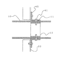
本発明の第1実施形態に係る撹拌機は、混和池で形成したフロックを、相互に衝突を繰り返させて集塊させるための横型の緩速撹拌機(横軸フロキュレータ)であって、図1は、説明図であり、図2は、図1のAの部分拡大図であり、図3は、図1のB―Bの位置で切断した断面図である。
First embodiment:
The stirrer according to the first embodiment of the present invention is a horizontal slow-speed stirrer (horizontal axis flocculator) for aggregating flocs formed in a mixing pool by repeatedly colliding with each other. 1 is an explanatory view, FIG. 2 is a partially enlarged view of A in FIG. 1, and FIG. 3 is a cross-sectional view taken along the line BB in FIG.
本発明に係る横型の緩速撹拌機1は、主軸10と、アーム20と、撹拌翼30とを備えている。
The horizontal
主軸10は、筒状であって軸受部40により支持され回転するようになっている。図2に示す通り、主軸10の内部であって、後述するアーム20との接合部11には鉄製の補強材12が内設されている。従って、L字型結合部42を介して主軸10とアーム20とを結合させるため螺子41でL字型結合部42と主軸10を結合させる場合に、螺子41が補強材12と螺合するようになっている。主軸10の材質は、カーボン繊維入りガラス繊維強化プラスチックであって、通常使用されるガラス繊維を含む繊維で補強された繊維体積率が30乃至60%のガラス繊維強化プラスチックの繊維部分の一部をカーボン繊維に置き換えたもので、カーボン繊維が繊維体積率30乃至60%の中の少なくとも5乃至20%含有されているものである。
The
アーム20は、後述する撹拌翼30が結合される部材であって、長手方向に対し直角断面形状が矩形であって、主軸10の回転により撹拌翼30と共に回転するようになっている。アーム20の材質は、主軸10と同じでカーボン繊維入りガラス繊維強化プラスチックである。
The
図3に示す通り、撹拌翼30は、主軸10の回転でアーム20と共に回転してフロックを成長させる機能を有するので、回転方向Xに対し広い面積を有するように形成されており、板厚を薄くしたときでも水の圧力に抗しうるように長手方向に対し直角断面形状がコの字形状をしている。撹拌翼30の材質は、主軸10と同じでカーボン繊維入りガラス繊維強化プラスチックである。
As shown in FIG. 3, the
上記構成の横型の緩速撹拌機1は、図5乃至図8に示す通り、主軸10、アーム20及び撹拌翼30の材質がすべて同じ材質であって、カーボン繊維が繊維体積率30乃至60%の中の少なくとも5乃至20%含有されているカーボン繊維入りガラス繊維強化プラスチックで成形されているので、従来品の撹拌翼が合成木材で成形され、主軸及びアームが鉄若しくはステンレスで成形されている緩速撹拌機と比較し、緩速撹拌機1の製品重量を約40%低減することが可能となる。従って、輸送、搬入・搬出、据付工事を容易に行うことができると共に、据付工事に掛るコストの低減が可能になる。また、軸受部40に係る荷重を低減することができ軸受部40の部材の交換間隔を1.5倍に延長することができ、維持管理を容易にすることが可能となる。
As shown in FIGS. 5 to 8, the horizontal
更に、カーボン繊維入りガラス繊維強化プラスチック製としたので錆が発生せず、耐光性も良好であるので、耐腐食性向上のため主軸10、アーム20及び撹拌翼30への塗装が不要となり、維持管理を容易にすることが可能となる。
Furthermore, because it is made of glass fiber reinforced plastic with carbon fiber, it does not generate rust and has good light resistance, so it is not necessary to paint on the
また、アーム20と接続される主軸10の接合部11の内部に補強材12が内設されているので、L字型結合部42を主軸10に結合させるときに、L字型結合部42を螺子41で補強材12と螺合結合させることができ、応力が集中する接合部11に亀裂が生じる等の不具合が発生するのを防止し、製品寿命を延長することが可能となる。
Further, since the reinforcing member 12 is provided inside the joint portion 11 of the
また、撹拌翼30の断面形状をコの字形としたので、従来形状より撹拌翼30の厚さを低減することが可能となると共に、撹拌翼30の形状を幅100mm、フランジ部25mm、板厚6mmとした場合であっても撹拌翼30の曲げ剛性を合成木材で成形されている従来品と同程度に確保することが可能となる。
Moreover, since the cross-sectional shape of the
第2実施形態:
本発明の第2実施形態に係る撹拌機は、混和池に凝集剤及び滅菌剤・酸化剤・アルカリ剤等の薬品を添加し、これらを急速かつ均一に混和するための急速撹拌機(ミキサ)であって、第1実施形態とは異なりアームがなく、構成が異なる部分について主に以下説明する。
Second embodiment:
A stirrer according to the second embodiment of the present invention is a rapid stirrer (mixer) for adding a flocculant and chemicals such as a sterilizing agent, an oxidizing agent, and an alkaline agent to a mixing pond and mixing them rapidly and uniformly. However, unlike the first embodiment, a portion having no arm and having a different configuration will be mainly described below.
本発明に係る急速撹拌機1は、図4に示す通り、主軸10と、撹拌翼30とを備えている。
The
主軸10は、円柱状であって、カーボン繊維入りガラス繊維強化プラスチックで成形されている。
The
撹拌翼30は、主軸10の末端に結合している円盤部31と円盤部31の周縁に付設されている羽根部32より形成されていて、材質は、主軸10と同じカーボン繊維入りガラス繊維強化プラスチックである。
The stirring
上記構成の急速撹拌機1は、図9乃至図11に示す通り、主軸10及び撹拌翼30の材質がすべて同じ材質であって、カーボン繊維が繊維体積率30乃至60%の中の少なくとも5乃至20%含有されているカーボン繊維入りガラス繊維強化プラスチックで成形されているので、主軸及び撹拌翼が鉄若しくはステンレスで成形されている従来品に比較して、急速撹拌機1の製品重量を約70%低減することが可能となる。従って、輸送、搬入・搬出、据付工事を容易に行うことができ、据付工事に掛るコストの低減が可能となる。
As shown in FIGS. 9 to 11, the
更に、カーボン繊維入りガラス繊維強化プラスチックとしたので錆が発生しないため、耐腐食性向上のため主軸10及び撹拌翼30への塗装が不要となり、維持管理を容易にすることが可能となる。
Further, since the glass fiber reinforced plastic with carbon fiber is used, rust does not occur, so that the coating on the
尚、上記実施形態1及び2においては、主軸10、アーム20が備えてある場合にはアーム20、撹拌翼30を全てカーボン繊維入りガラス繊維強化プラスチックで成形した場合を説明した。しかし、主軸10だけをカーボン繊維入りガラス繊維強化プラスチックにした場合には、主軸10の重量を55%低減することが可能となり、アーム20だけをカーボン繊維入りガラス繊維強化プラスチックにした場合には、アーム20の重量を40%低減することが可能となる。また、緩速撹拌機において、撹拌翼30だけをカーボン繊維入りガラス繊維強化プラスチックにした場合、合成木材で成形されている従来品に対し重量を低減することはできないが、塗装が不要となり維持管理を容易とすることが可能となる。
In the first and second embodiments, the case where the
1 撹拌機
10 主軸
11 接合部
12 補強材
20 アーム
30 撹拌翼
31 円盤部
32 羽根部
40 軸受部
41 螺子
42 L字型結合部
DESCRIPTION OF
Claims (5)
前記主軸・前記アーム・前記撹拌翼の中の少なくともいずれか一にカーボン繊維入りガラス繊維強化プラスチックを使用したことを特徴とする撹拌機。 In a stirrer comprising a main shaft used in a water treatment facility, an arm connected to the main shaft, and a stirring blade connected to the arm,
A stirrer using a glass fiber reinforced plastic containing carbon fiber as at least one of the main shaft, the arm, and the stirring blade.
前記主軸・前記撹拌翼の中の少なくともいずれかにカーボン繊維入りガラス繊維強化プラスチックを使用したことを特徴とする撹拌機。 In a stirrer comprising a main shaft used in a water treatment facility, and a stirring blade connected to the main shaft,
A stirrer characterized in that a glass fiber reinforced plastic containing carbon fiber is used for at least one of the main shaft and the stirring blade.
The stirrer according to any one of claims 1 to 4, wherein the glass fiber reinforced plastic containing carbon fibers contains carbon fibers in at least 5 to 20% of a fiber volume ratio of 30 to 60%. .
Priority Applications (1)
| Application Number | Priority Date | Filing Date | Title |
|---|---|---|---|
| JP2008197391A JP4912365B2 (en) | 2008-07-31 | 2008-07-31 | mixer |
Applications Claiming Priority (1)
| Application Number | Priority Date | Filing Date | Title |
|---|---|---|---|
| JP2008197391A JP4912365B2 (en) | 2008-07-31 | 2008-07-31 | mixer |
Publications (2)
| Publication Number | Publication Date |
|---|---|
| JP2010029828A true JP2010029828A (en) | 2010-02-12 |
| JP4912365B2 JP4912365B2 (en) | 2012-04-11 |
Family
ID=41734969
Family Applications (1)
| Application Number | Title | Priority Date | Filing Date |
|---|---|---|---|
| JP2008197391A Active JP4912365B2 (en) | 2008-07-31 | 2008-07-31 | mixer |
Country Status (1)
| Country | Link |
|---|---|
| JP (1) | JP4912365B2 (en) |
Cited By (6)
| Publication number | Priority date | Publication date | Assignee | Title |
|---|---|---|---|---|
| JP2012210590A (en) * | 2011-03-31 | 2012-11-01 | Sumitomo Heavy Industries Environment Co Ltd | Sludge scraping machine |
| JP2014042864A (en) * | 2012-08-24 | 2014-03-13 | Suido Kiko Kaisha Ltd | Flocculator |
| JP2014087770A (en) * | 2012-10-31 | 2014-05-15 | Toho Tenax Co Ltd | Agitator |
| JP5583260B1 (en) * | 2013-10-18 | 2014-09-03 | 水道機工株式会社 | mixer |
| JP5657077B1 (en) * | 2013-10-18 | 2015-01-21 | 水道機工株式会社 | mixer |
| JP2015517899A (en) * | 2012-03-30 | 2015-06-25 | インベント ウムウェルト− ウント フェルファーレンステヒニック アーゲー | Horizontal stirring device |
Citations (5)
| Publication number | Priority date | Publication date | Assignee | Title |
|---|---|---|---|---|
| JPS4830057Y1 (en) * | 1968-05-30 | 1973-09-12 | ||
| JPH09239251A (en) * | 1996-03-07 | 1997-09-16 | Fuji Photo Film Co Ltd | Dispersing machine |
| JP2006051418A (en) * | 2004-08-10 | 2006-02-23 | Kobelco Eco-Solutions Co Ltd | Aeration processing method |
| JP2007154088A (en) * | 2005-12-07 | 2007-06-21 | Toray Ind Inc | Two-pot type curable resin composition for fiber-reinforced composite material, fiber-reinforced composite material and method for producing the same |
| JP2008068232A (en) * | 2006-09-15 | 2008-03-27 | Sumitomo Heavy Industries Environment Co Ltd | Flocculator |
-
2008
- 2008-07-31 JP JP2008197391A patent/JP4912365B2/en active Active
Patent Citations (5)
| Publication number | Priority date | Publication date | Assignee | Title |
|---|---|---|---|---|
| JPS4830057Y1 (en) * | 1968-05-30 | 1973-09-12 | ||
| JPH09239251A (en) * | 1996-03-07 | 1997-09-16 | Fuji Photo Film Co Ltd | Dispersing machine |
| JP2006051418A (en) * | 2004-08-10 | 2006-02-23 | Kobelco Eco-Solutions Co Ltd | Aeration processing method |
| JP2007154088A (en) * | 2005-12-07 | 2007-06-21 | Toray Ind Inc | Two-pot type curable resin composition for fiber-reinforced composite material, fiber-reinforced composite material and method for producing the same |
| JP2008068232A (en) * | 2006-09-15 | 2008-03-27 | Sumitomo Heavy Industries Environment Co Ltd | Flocculator |
Cited By (6)
| Publication number | Priority date | Publication date | Assignee | Title |
|---|---|---|---|---|
| JP2012210590A (en) * | 2011-03-31 | 2012-11-01 | Sumitomo Heavy Industries Environment Co Ltd | Sludge scraping machine |
| JP2015517899A (en) * | 2012-03-30 | 2015-06-25 | インベント ウムウェルト− ウント フェルファーレンステヒニック アーゲー | Horizontal stirring device |
| JP2014042864A (en) * | 2012-08-24 | 2014-03-13 | Suido Kiko Kaisha Ltd | Flocculator |
| JP2014087770A (en) * | 2012-10-31 | 2014-05-15 | Toho Tenax Co Ltd | Agitator |
| JP5583260B1 (en) * | 2013-10-18 | 2014-09-03 | 水道機工株式会社 | mixer |
| JP5657077B1 (en) * | 2013-10-18 | 2015-01-21 | 水道機工株式会社 | mixer |
Also Published As
| Publication number | Publication date |
|---|---|
| JP4912365B2 (en) | 2012-04-11 |
Similar Documents
| Publication | Publication Date | Title |
|---|---|---|
| JP4912365B2 (en) | mixer | |
| CN102773473B (en) | Iron nickel chrome molybdenum base powder for laser cladding and method for preparing same | |
| CN101544461A (en) | Sludge stirring system | |
| CN201744320U (en) | Vertical shaft type dual-turbine mixer | |
| CN103101112A (en) | Novel elastic stirring blade for concrete hopper | |
| CN102371130A (en) | Vertical shaft-type double-turbine mixer | |
| CN202318572U (en) | Novel elastic stirring blade for concrete hopper | |
| JP5106368B2 (en) | Impeller core material, impeller and agitator | |
| CN205478348U (en) | Dive formula sewage pump of high -efficient blowdown | |
| CN206828110U (en) | A kind of efficiently water process agitator tank | |
| CN202700496U (en) | Stirring device for diphenyl ketone hydrolysis kettle | |
| CN204585545U (en) | Self-compacting concrete stirs hopper | |
| CN207756018U (en) | A kind of agitating device | |
| CN209138422U (en) | A kind of glass steel metal agitating shaft of anticorrosion antiwear | |
| CN202876743U (en) | Stirring paddle for packaging composite anticorrosive coating | |
| Van Berkel | Cleaner production: a profitable road for sustainable development of Australian industry | |
| KR200167609Y1 (en) | Paddle of agitator wing in condenser | |
| CN207769584U (en) | A kind of agitating paddle | |
| CN206201197U (en) | A kind of upright shaft stirring machine cylinder of use novel lining plate | |
| CN212040003U (en) | Stirring tank | |
| CN205462087U (en) | Puddler for fodder mixing machine | |
| CN219784402U (en) | Stirring shaft and gypsum neutralization tank | |
| CN211754857U (en) | Be applied to stirring structure of continuous acidolysis dissolving tank | |
| CN210595298U (en) | Heavy-duty anticorrosive lining of pickling tank of sulfuric acid process titanium dioxide plant | |
| CN214715788U (en) | Stirring device replacing submersible stirrer |
Legal Events
| Date | Code | Title | Description |
|---|---|---|---|
| A621 | Written request for application examination |
Free format text: JAPANESE INTERMEDIATE CODE: A621 Effective date: 20100219 |
|
| A977 | Report on retrieval |
Free format text: JAPANESE INTERMEDIATE CODE: A971007 Effective date: 20110823 |
|
| A131 | Notification of reasons for refusal |
Free format text: JAPANESE INTERMEDIATE CODE: A131 Effective date: 20110830 |
|
| A521 | Request for written amendment filed |
Free format text: JAPANESE INTERMEDIATE CODE: A523 Effective date: 20111021 |
|
| TRDD | Decision of grant or rejection written | ||
| A01 | Written decision to grant a patent or to grant a registration (utility model) |
Free format text: JAPANESE INTERMEDIATE CODE: A01 Effective date: 20120110 |
|
| A01 | Written decision to grant a patent or to grant a registration (utility model) |
Free format text: JAPANESE INTERMEDIATE CODE: A01 |
|
| A61 | First payment of annual fees (during grant procedure) |
Free format text: JAPANESE INTERMEDIATE CODE: A61 Effective date: 20120117 |
|
| R150 | Certificate of patent or registration of utility model |
Free format text: JAPANESE INTERMEDIATE CODE: R150 Ref document number: 4912365 Country of ref document: JP Free format text: JAPANESE INTERMEDIATE CODE: R150 |
|
| FPAY | Renewal fee payment (event date is renewal date of database) |
Free format text: PAYMENT UNTIL: 20150127 Year of fee payment: 3 |
|
| R250 | Receipt of annual fees |
Free format text: JAPANESE INTERMEDIATE CODE: R250 |
|
| R250 | Receipt of annual fees |
Free format text: JAPANESE INTERMEDIATE CODE: R250 |
|
| R250 | Receipt of annual fees |
Free format text: JAPANESE INTERMEDIATE CODE: R250 |
|
| R250 | Receipt of annual fees |
Free format text: JAPANESE INTERMEDIATE CODE: R250 |
|
| R250 | Receipt of annual fees |
Free format text: JAPANESE INTERMEDIATE CODE: R250 |
|
| R250 | Receipt of annual fees |
Free format text: JAPANESE INTERMEDIATE CODE: R250 |
|
| R250 | Receipt of annual fees |
Free format text: JAPANESE INTERMEDIATE CODE: R250 |
|
| R250 | Receipt of annual fees |
Free format text: JAPANESE INTERMEDIATE CODE: R250 |
|
| R250 | Receipt of annual fees |
Free format text: JAPANESE INTERMEDIATE CODE: R250 |
|
| R250 | Receipt of annual fees |
Free format text: JAPANESE INTERMEDIATE CODE: R250 |