JP2010028971A - Motor drive control apparatus and electric power steering system - Google Patents
Motor drive control apparatus and electric power steering system Download PDFInfo
- Publication number
- JP2010028971A JP2010028971A JP2008187031A JP2008187031A JP2010028971A JP 2010028971 A JP2010028971 A JP 2010028971A JP 2008187031 A JP2008187031 A JP 2008187031A JP 2008187031 A JP2008187031 A JP 2008187031A JP 2010028971 A JP2010028971 A JP 2010028971A
- Authority
- JP
- Japan
- Prior art keywords
- current
- value
- estimated
- phase
- electric motor
- Prior art date
- Legal status (The legal status is an assumption and is not a legal conclusion. Google has not performed a legal analysis and makes no representation as to the accuracy of the status listed.)
- Granted
Links
Images


Abstract
Description
本発明は、モータ駆動制御装置、及びこれを備えた電動パワーステアリング装置に関するものである。 The present invention relates to a motor drive control device and an electric power steering device including the same.
電動モータのフィードバック制御では、各相電流が必要になるが、一つのシャント抵抗で全電流を検出し、これに基づいて各相電流を検出する一シャント方式が知られている。
相電流を検出するものとして、基本ベクトルとゼロベクトルとを組み合わせた複数のPWMパターンを生成すると共に、この基本ベクトルの大きさを、スイッチングの通電時間に対応させ、検出タイミングをデューティ比に合わせて変更するものがある(特許文献1参照)。
In the feedback control of the electric motor, each phase current is required. However, a single shunt system is known in which all currents are detected by one shunt resistor and each phase current is detected based on this current.
In order to detect the phase current, a plurality of PWM patterns combining a basic vector and a zero vector are generated, and the magnitude of this basic vector is made to correspond to the switching energization time, and the detection timing is matched to the duty ratio. There is something to change (see Patent Document 1).
一方、検出タイミングは固定しているものの、デューティ比の大きい相順にスイッチングの立ち上がり時間をずらしてPWM駆動を行い、スイッチングの立ち上がり時に各相電流を検出するものもある(特許文献2参照)。
しかしながら、特許文献1に記載された従来例にあっては、検出タイミングをデューティ比に応じて変更しなければならず、そのために特殊なコントローラが必要になってしまう。また、特許文献2に記載された従来例にあっては、スイッチングの立ち上がり時間を相毎にずらす必要があるので、各相のデューティ比が大きい値で均衡すると、電流検出が困難となる。したがって、デューティ比の使用帯域を限定せざるを得なくなるが、これではモータ出力が制限されてしまう。
However, in the conventional example described in
本発明の課題は、一シャント方式であっても簡易な構成とし、且つ電動モータの出力制限を防ぐことである。 An object of the present invention is to provide a simple configuration even in the case of a single shunt system, and to prevent output limitation of an electric motor.
請求項1に係るモータ駆動制御装置は、電動モータを駆動制御するモータ駆動制御装置であって、前記電動モータに対する電流指令値を算出し、算出した電流指令値と前記電動モータの回路特性とに基づいて電圧指令値を算出する算出手段と、該算出手段が算出した電圧指令値に基づいて前記電動モータを駆動する駆動手段と、前記電動モータに通電される全電流を検出する一つの電流検出手段と、前記算出手段が算出した電圧指令値に応じて前記電動モータに通電される全電流を推定する電流推定手段と、前記電流検出手段が検出した検出値と前記電流推定手段が推定した推定値とに基づいて前記電動モータの回路抵抗を推定する抵抗推定手段とを備え、前記算出手段は、前記電圧指令値の算出に用いる前記回路特性内の回路抵抗値を、前記抵抗推定手段が推定した推定値に更新する。
The motor drive control device according to
請求項2に係るモータ駆動制御装置は、前記電動モータは、多相モータで構成され、前記電流推定手段は、前記算出手段が算出した各相の電圧指令値に応じて前記電動モータに通電される各相の電流を推定する相電流推定手段と、該相電流推定手段が推定した各相の推定値に応じて前記電動モータに通電される全電流を推定する全電流推定手段と、で構成される。
In the motor drive control device according to
請求項3に係るモータ駆動制御装置は、前記全電流推定手段は、前記相電流推定手段が推定した各相の推定値のうち、絶対値が最大となる推定値を、前記電動モータに通電される全電流として推定する。
請求項4に係るモータ駆動制御装置は、前記抵抗推定手段は、前記電流検出手段が検出した検出値と前記全電流推定手段が推定した推定値との差分に基づいて前記電動モータの回路抵抗を推定する。
According to a third aspect of the present invention, in the motor drive control device, the total current estimating means is configured to energize the electric motor with an estimated value having the maximum absolute value among estimated values of each phase estimated by the phase current estimating means. It is estimated as the total current.
According to a fourth aspect of the present invention, in the motor drive control device, the resistance estimation unit calculates a circuit resistance of the electric motor based on a difference between a detection value detected by the current detection unit and an estimation value estimated by the total current estimation unit. presume.
請求項5に係るモータ駆動制御装置は、前記抵抗推定手段は、各相のうち、前記相電流推定手段が推定した推定値の絶対値が最大となった相を選出相とすると共に、当該選出相以外の相を非選出相とし、前記選出相では、前記電流検出手段が検出した検出値と前記全電流推定手段が推定した推定値との差分に基づいて前記電動モータの回路抵抗を推定し、前記非選出相では、前記相電流推定手段が推定した推定値と前記全電流推定手段が推定した推定値との比率に基づいて前記電動モータの回路抵抗を推定する。
In the motor drive control device according to
請求項6に係る電動パワーステアリング装置は、請求項1〜5の何れか一項に記載のモータ駆動制御装置を備え、前記電動モータは、ステアリング系にアシストトルクを伝達し、前記算出手段は、運転者の操舵トルクに応じて前記電動モータに対する電流指令値を算出する。 An electric power steering apparatus according to a sixth aspect includes the motor drive control apparatus according to any one of the first to fifth aspects, wherein the electric motor transmits an assist torque to a steering system, and the calculation unit includes: A current command value for the electric motor is calculated according to the steering torque of the driver.
本発明によれば、算出した電圧指令値に基づいて電動モータを駆動するフィードフォワード制御を行うことで、各相電流を検出しなくて済む。したがって、特殊なコントローラや複雑な演算処理が不要となり、簡易な構成にすることができる。また、電流検出が困難となりモータ出力が制限される、といった事態も回避することができる。
また、電動モータに通電される全電流を推定すると共に、一つの電流検出手段で全電流を検出し、これら推定値と検出値とに基づいて、電動モータの回路抵抗を推定し、電圧指令値の算出に用いる回路抵抗を、その推定値に更新することで、フィードフォワード制御にとって問題となるロバスト性の低下を防止することができる。
According to the present invention, it is not necessary to detect each phase current by performing feedforward control for driving the electric motor based on the calculated voltage command value. Therefore, a special controller and complicated arithmetic processing are not required, and a simple configuration can be achieved. Further, it is possible to avoid a situation where current detection is difficult and the motor output is limited.
Further, the total current supplied to the electric motor is estimated, the total current is detected by one current detection means, the circuit resistance of the electric motor is estimated based on the estimated value and the detected value, and the voltage command value By updating the circuit resistance used for the calculation to the estimated value, it is possible to prevent a decrease in robustness that becomes a problem for feedforward control.
以下、本発明の実施の形態を図面に基づいて説明する。
〔第1実施形態〕
先ず、本実施形態の構成について説明する。
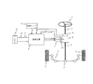
図1は、パワーステアリング装置の概略構成である。ステアリングホイール1は、ステアリングシャフト2、ラックアンドピニオン3、タイロッド4を順に介して車輪5に連結されており、ステアリングシャフト2には、減速機6を介して電動モータ7が連結されている。この電動モータ7は、制御装置8によって駆動制御されることにより、運転者のステアリング操作に対してアシストトルクを付与する。
Hereinafter, embodiments of the present invention will be described with reference to the drawings.
[First Embodiment]
First, the configuration of the present embodiment will be described.
FIG. 1 is a schematic configuration of a power steering apparatus. The
制御装置8は、イグニッションスイッチ9及びヒューズ10を介して接続されたバッテリ11から電力供給されると共に、トルクセンサ12で検出した操舵トルクTと、レゾルバ13の検出信号sinθ及びcosθと、車速センサ14で検出した車速Vと、が入力される。
トルクセンサ12は、ステアリングシャフト2における入力軸と出力軸との間に介挿されたトーションバーの捩れ角を、サーチコイルによって磁束の変化として検出するものであり、このサーチコイルに誘起される電圧が操舵トルクTに換算される。例えば、図2に示すように、電圧がV0のときに操舵トルクTが0となり、電圧がV0から増加するほど右方向への操舵トルクTが増加し、電圧がV0から減少するほど左方向への操舵トルクTが増加する。
The
The
レゾルバ13は、1相の励磁信号sinωtが入力されるときに、モータ回転角θに応じて、正弦及び余弦に対応した2相の検出信号sinθ及びcosθを出力する。
次に、制御装置8で実行される第1実施形態のモータ駆動制御処理を、図3のブロック図に基づいて説明する。
先ず、操舵トルクT及び車速Vに応じて、各相の電流指令値Irefj(j=u、v、
w)を算出する。具体的には、操舵トルクTが所定値Ts以下であるときには、電流指令値Irefjが0を維持し、操舵トルクTが大きいほど、電流指令値Irefjが大きく
なり、且つ車速Vが高いほど、電流指令値Irefjが小さくなるように設定されている
。
When the one-phase excitation signal sinωt is input, the
Next, the motor drive control process of the first embodiment executed by the
First, according to the steering torque T and the vehicle speed V, the current command value Irefj (j = u, v,
w) is calculated. Specifically, when the steering torque T is less than or equal to a predetermined value Ts, the current command value Irefj is maintained at 0, and the current command value Irefj increases as the steering torque T increases and the vehicle speed V increases. The command value Irefj is set to be small.
フィードフォワード電流制御器21は、下記(1)式に示すように、モータ特性式を含めた伝達関数を用い、各相の電流指令値Irefjに応じて、各相の電圧指令値Vjを算出する。
Vj=C(s)Irefj={(Ls+R^)/(T1s+1)}Irefj
………(1)
ここで、Lはインダクタンス値、R^は推定抵抗値、T1は所望のシステムカットオフ時定数である。推定抵抗値R^は、電動モータ7の回路抵抗である。伝達関数C(s)は、ハードを含め電流指令値から実電流値までの動特性が、所望の動特性[1/(T1s+1)]となるように構成されたフィードフォワード制御器21であり、推定抵抗値R^を用いることで、フィードフォワード制御器21にとって課題となるロバスト性不足に起因した過電流の発生を防止することができる。なお、プログラム構成に微分器が導入できる場合には、システムカットオフ時定数T1をゼロにする。
The feedforward
Vj = C (s) Irefj = {(Ls + R ^) / (T 1 s + 1)} Irefj
……… (1)
Here, L is an inductance value, R ^ is an estimated resistance value, and T 1 is a desired system cutoff time constant. The estimated resistance value R ^ is the circuit resistance of the
EMF補償器22は、逆起電圧EMFを補償するためのEMF補償値を出力し、加算器23は、電圧指令値VjにEMF補償値を加算し、デューティ変換器24は、EMF補償を施した電圧指令値Vjをデューティ指令値Djに変換しインバータ25へ出力する。
インバータ25は、各相のデューティ指令値Djに基づいてPWM駆動され、電動モータ7に駆動電圧を印加する。インバータ25の下段には、シャント抵抗で構成された単一の電流検出器26が設けられており、この電流検出器26による電動モータ7に通電される全電流検出値Idctを検出する。
The
The
一方、相電流推定器31は、フィードフォワード制御器21が算出した電圧指令値Vjを入力し、下記(2)式の伝達関数に従って相電流推定値Ij^を演算する。
Ij^={1/(Ls+R^)}Vj ………(2)
全電流推定器32は、相電流推定値Ij^を入力し、全電流検出値Idctに相当する全電流推定値I^を演算する。
On the other hand, the phase
Ij ^ = {1 / (Ls + R ^)} Vj (2)
The total
例えば、正弦波電流にて駆動するシステムの場合、モータに流れる各相の電流は、図4のような波形となる。電流検出器26をシャント抵抗で構成し、且つサンプリング方式をピークホールド方式とした場合、電流検出器26では、図5のような波形、つまり各相の電流の最大値をとる波形として検出される。
For example, in the case of a system driven by a sine wave current, the current of each phase flowing through the motor has a waveform as shown in FIG. When the
したがって、全電流推定器32は、先ず電流推定値Ij^の夫々を絶対値化し、そのうちの最大値を選択することで、全電流推定値I^を演算する。
加算器33は、全電流検出値Idctと全電流推定値I^との差分ΔIを算出する。
抵抗推定器34は、差分ΔIを入力し、電動モータ7の推定抵抗値R^を演算する。
Therefore, the total
The
The
ここで、推定抵抗値R^の演算原理について説明する。
システムの温度変化などに起因して、現在の推定抵抗値R^からの変化分をΔRとし、逆起電圧EMFが補償されているとした場合、電圧Vと実電流iとは、下記(3)式で表される。
V=L(di/dt)+(R^+ΔR)i ………(3)
一方、電圧Vと電流推定値i^とは、下記(4)式で表される。
V=L(di^/dt)+R^i^ ………(4)
上記(3)及び(4)式より、変化分ΔRは、下記(5)式で表される。
L(di/dt)+(R^+ΔR)i=L(di^/dt)+R^i^
ΔRi=L(di^/dt)−L(di/dt)+R^i^−R^i
ΔRi=L(d/dt)(i^−i)+R^(i^−i)
ΔR={L(d/dt)(i^−i)+R^(i^−i)}/i
………(5)
Here, the calculation principle of the estimated resistance value R ^ will be described.
When the change from the current estimated resistance value R ^ is ΔR and the back electromotive force EMF is compensated due to the temperature change of the system, the voltage V and the actual current i are as follows (3 ) Expression.
V = L (di / dt) + (R ^ + ΔR) i (3)
On the other hand, the voltage V and the current estimated value i ^ are expressed by the following equation (4).
V = L (di ^ / dt) + R ^ i ^ (4)
From the above equations (3) and (4), the change ΔR is expressed by the following equation (5).
L (di / dt) + (R ^ + ΔR) i = L (di ^ / dt) + R ^ i ^
ΔRi = L (di ^ / dt) -L (di / dt) + R ^ i ^ -R ^ i
ΔRi = L (d / dt) (i ^ -i) + R ^ (i ^ -i)
ΔR = {L (d / dt) (i ^ -i) + R ^ (i ^ -i)} / i
......... (5)
電流推定値i^と実電流iとの差分e(=i^−i)とすると、変化分ΔRは、下記(6)式で表される。
ΔR={L(d/dt)e+R^e}/i ………(6)
上記(6)式は、1相分を表しており、全電流に置換して考えることができる。すなわち、実電流iを全電流検出値Idctとし、電流推定値i^を全電流推定値I^として考えれば、下記(7)式が導かれる。
ΔR={L(d/dt)e+R^e}/Idct
=(Ls+R^)e/Idct ………(7)
Assuming that the difference e (= i ^ -i) between the current estimated value i ^ and the actual current i, the change ΔR is expressed by the following equation (6).
ΔR = {L (d / dt) e + R ^ e} / i (6)
The above equation (6) represents one phase and can be considered by replacing it with the total current. That is, when the actual current i is considered as the total current detection value Idct and the current estimation value i ^ is considered as the total current estimation value I ^, the following equation (7) is derived.
ΔR = {L (d / dt) e + R ^ e} / Idct
= (Ls + R ^) e / Idct (7)
ここでは、式の構造上、eの微分値が必要になるが、微分器の導入が好ましくない場合がある。すなわち、全電流検出値Idctにノイズが加わると微分値に大きな影響を与え、抵抗推定器34による推定誤差が大きくなってしまう。そこで、下記(8)式に示すように、フィルタ構成を付加することで、ノイズ耐性を向上させる。
ΔR=(g/Idct){(Ls+R^)/(T2s+1)}e ………(8)
ここで、T2はノイズを十分に除去できる所望のフィルタカットオフ時定数であり、gは推定値の収束速度を左右する収束ゲインである。
Here, the differential value of e is required due to the structure of the formula, but the introduction of a differentiator may not be preferable. That is, if noise is added to the total current detection value Idct, the differential value is greatly affected, and the estimation error by the
ΔR = (g / Idct) {(Ls + R ^) / (T 2 s + 1)} e (8)
Here, T 2 is a desired filter cutoff time constant capable of sufficiently removing noise, and g is a convergence gain that affects the convergence speed of the estimated value.
抵抗推定器34は、上記のように変化分ΔRを演算し、現在の推定抵抗値R^に加算してから新たな推定抵抗値R^として更新し、フィードフォワード電流制御器21へ出力する。
フィードフォワード電流制御器21は、入力された推定抵抗値R^を、新たな推定抵抗値R^として更新して、電圧指令値Vjの算出に用いる。
The
The feedforward
次に、本実施形態の作用効果について説明する。
フィードバック制御を行うもので、一シャント方式を採用すると、各相電流を検出するため特殊なコントローラや演算処理が必要となるばかりか、電流検出に条件が課され、モータ出力が制限されることもあった。
Next, the effect of this embodiment is demonstrated.
When one shunt method is used, feedback control is performed. In addition to requiring a special controller and arithmetic processing to detect each phase current, conditions are imposed on current detection and motor output may be limited. there were.
そこで、本実施形態では、フィードフォワード制御を行っている。これにより、各相電流を検出しなくて済むので、特殊なコントローラや演算処理が不要となり、簡易な構成にすることができる。また、電流検出が困難となりモータ出力が制限されるといった事態も回避することができる。
また、電動モータ7に通電される全電流推定値I^を演算すると共に、一つの電流検出器26で全電流検出値Idctを検出し、これら全電流推定値I^と全電流検出値Idctとに基づいて、電動モータ7の推定抵抗値R^を推定し、この推定抵抗値R^により、電圧指令値Vjの算出に用いる推定抵抗値R^を更新することで、フィードフォワード制御にとって問題となるロバスト性の低下を防止することができる。
Therefore, in this embodiment, feedforward control is performed. This eliminates the need to detect each phase current, so that a special controller and arithmetic processing are not required, and a simple configuration can be achieved. In addition, it is possible to avoid a situation where current detection becomes difficult and the motor output is limited.
In addition, the total current estimated value I ^ energized to the
全電流推定値I^の演算については、先ず電圧指令値Vjに応じて相電流推定値Ij^を演算し、この相電流推定値Ij^に応じて全電流推定値I^を演算することで、容易に全電流推定値I^を演算することができる。特に、相電流推定値Ij^のうち、絶対値が最大となる推定値を、全電流推定値I^として演算するだけなので、容易に演算することができる。 Regarding the calculation of the total current estimated value I ^, first, the phase current estimated value Ij ^ is calculated according to the voltage command value Vj, and the total current estimated value I ^ is calculated according to the phase current estimated value Ij ^. The total current estimated value I ^ can be easily calculated. In particular, among the phase current estimated values Ij ^, the estimated value having the maximum absolute value is simply calculated as the total current estimated value I ^, so that it can be easily calculated.
推定抵抗値R^の演算については、前記(8)式を用い、全電流検出値Idctと全電流推定値Ij^との差分ΔIに基づいて推定抵抗値R^を演算することで、容易に推定抵抗値R^を演算することができる。
以上より、フィードフォワード電流制御器21が「算出手段」に対応し、インバータ25が「駆動手段」に対応し、電流検出器26が「電流検出手段」に対応し、相電流推定器31及び全電流推定器32が「電流推定手段」に対応し、抵抗推定器34が「抵抗推定手段」に対応している。また、相電流推定器31が「相電流推定手段」に対応し、全電流推定器32が「電流推定手段」に対応している。
As for the calculation of the estimated resistance value R ^, it is easy to calculate the estimated resistance value R ^ based on the difference ΔI between the total current detection value Idct and the total current estimation value Ij ^ by using the equation (8). The estimated resistance value R ^ can be calculated.
From the above, the feedforward
〔第2実施形態〕
次に、制御装置8で実行される第2実施形態のモータ駆動制御処理を、図6のブロック図に基づいて説明する。
前述した第1実施形態では、三相モータの各相の回路抵抗が均衡している場合を想定したものであるが、この第2実施形態では、三相モータの各相の回路抵抗が異なっている場合を想定したものである。
[Second Embodiment]
Next, the motor drive control process of the second embodiment executed by the
In the first embodiment described above, it is assumed that the circuit resistance of each phase of the three-phase motor is balanced, but in this second embodiment, the circuit resistance of each phase of the three-phase motor is different. It is assumed that there is.
そこで、相電流推定値Ij^の絶対値が最大となった相を選出相mとし、それ以外の相を非選出相nとして判定する相判定器41を設け、その判定結果を抵抗推定器34へ出力する。
抵抗推定器34は、選出相mでは、前述した第1実施形態で述べたように、前記(8)式を用い、全電流検出値Idctと全電流推定値Ij^との差分ΔIに基づいて推定抵抗値Rm^を演算する。一方、非選出相nでは、下記(9)式に示すように、相電流推定値In^と全電流推定値I^(=Im^)との比率[|In^|/|I^|]に基づいて、推定抵抗値Rn^を演算する。
Therefore, a
In the selection phase m, the
Rn^=Rn^+ΔRm(|In^|/|I^|)2 ………(9)
推定抵抗器34は、上記のように非選出相nの抵抗変化分をΔRm(|In^|/|I^|)2で演算し、現在の推定抵抗値Rn^に加算してから新たな推定抵抗値Rn^として更新し、フィードフォワード電流制御器21へ出力する。
フィードフォワード電流制御器21は、入力された各相の推定抵抗値Rj^を、新たな推定抵抗値Rj^として更新して、電圧指令値Vjの算出に用いる。
Rn ^ = Rn ^ + ΔRm (| In ^ | / | I ^ |) 2 (9)
As described above, the estimated
The feedforward
次に、本実施形態の作用効果について説明する。
各相の推定抵抗値Rj^が常に同一であるとは限らない。
そこで、本実施形態では、相電流推定値Ij^の絶対値が最大となった相を選出相mとし、それ以外の相を非選出相nとし、選出相mでは、全電流検出値Idctと全電流推定値Ij^との差分ΔIに基づいて推定抵抗値Rm^を演算し、非選出相nでは、相電流推定値In^と全電流推定値I^との比率に基づいて推定抵抗値Rn^を演算する。これにより、各相の推定抵抗値Rj^が不均衡であっても、各相の推定抵抗値Rj^を正確に演算することができる。
以上より、抵抗推定器34及び相判定器41が「抵抗推定手段」に対応している。
Next, the effect of this embodiment is demonstrated.
The estimated resistance value Rj ^ of each phase is not always the same.
Therefore, in the present embodiment, the phase having the maximum absolute value of the phase current estimated value Ij ^ is set as the selected phase m, the other phases are set as the non-selected phase n, and in the selected phase m, the total current detection value Idct and Calculate the estimated resistance value Rm ^ based on the difference ΔI from the total current estimated value Ij ^. In the unselected phase n, the estimated resistance value is calculated based on the ratio between the phase current estimated value In ^ and the total current estimated value I ^. Rn ^ is calculated. Thereby, even if the estimated resistance value Rj ^ of each phase is unbalanced, the estimated resistance value Rj ^ of each phase can be accurately calculated.
From the above, the
〔第3実施形態〕
次に、第3実施形態について説明する。
この第3実施形態は、図7及び図8に示すように、電流検出器26を、インバータ25の上段に設けたものである。すなわち、電流検出器26を上段に設けたことを除き、図7では、第1実施形態と同一のモータ駆動制御処理を実行し、図8では、第2実施形態と同一のモータ駆動制御処理を実行する。
このように、電流検出器26が上段にあっても前述した作用効果を得ることができる。
[Third Embodiment]
Next, a third embodiment will be described.
In the third embodiment, as shown in FIGS. 7 and 8, the
Thus, even if the
1…ステアリングホイール、2…ステアリングシャフト、3…ラックアンドピニオン、4…タイロッド、5…車輪、6…減速機、7…電動モータ、8…制御装置、12…トルクセンサ、13…レゾルバ、14…車速センサ、21…フィードフォワード電流制御器、22…EMF補償器、23…加算器、24…デューティ変換器、25…インバータ、26…電流検出器、31…相電流推定器、32…全電流推定器、33…加算器、34…抵抗推定器、41…相判定器
DESCRIPTION OF
Claims (6)
前記電動モータに対する電流指令値を算出し、算出した電流指令値と前記電動モータの回路特性とに基づいて電圧指令値を算出する算出手段と、該算出手段が算出した電圧指令値に基づいて前記電動モータを駆動する駆動手段と、
前記電動モータに通電される全電流を検出する一つの電流検出手段と、前記算出手段が算出した電圧指令値に応じて前記電動モータに通電される全電流を推定する電流推定手段と、前記電流検出手段が検出した検出値と前記電流推定手段が推定した推定値とに基づいて前記電動モータの回路抵抗を推定する抵抗推定手段とを備え、
前記算出手段は、前記電圧指令値の算出に用いる前記回路特性内の回路抵抗値を、前記抵抗推定手段が推定した推定値に更新することを特徴とするモータ駆動制御装置。 A motor drive control device for driving and controlling an electric motor,
Calculating a current command value for the electric motor, calculating a voltage command value based on the calculated current command value and circuit characteristics of the electric motor; and based on the voltage command value calculated by the calculation unit Drive means for driving the electric motor;
One current detecting means for detecting the total current supplied to the electric motor, a current estimating means for estimating the total current supplied to the electric motor according to the voltage command value calculated by the calculating means, and the current Resistance estimation means for estimating circuit resistance of the electric motor based on the detection value detected by the detection means and the estimation value estimated by the current estimation means,
The motor drive control device, wherein the calculation means updates a circuit resistance value in the circuit characteristic used for calculation of the voltage command value to an estimated value estimated by the resistance estimation means.
前記電流推定手段は、前記算出手段が算出した各相の電圧指令値に応じて前記電動モータに通電される各相の電流を推定する相電流推定手段と、該相電流推定手段が推定した各相の推定値に応じて前記電動モータに通電される全電流を推定する全電流推定手段と、で構成されることを特徴とする請求項1に記載のモータ駆動制御装置。 The electric motor is composed of a multiphase motor,
The current estimation means includes a phase current estimation means for estimating a current of each phase energized to the electric motor according to a voltage command value of each phase calculated by the calculation means, and each of the phase current estimation means estimated by the phase current estimation means The motor drive control device according to claim 1, comprising: a total current estimation unit configured to estimate a total current supplied to the electric motor according to an estimated value of the phase.
前記選出相では、前記電流検出手段が検出した検出値と前記全電流推定手段が推定した推定値との差分に基づいて前記電動モータの回路抵抗を推定し、
前記非選出相では、前記相電流推定手段が推定した推定値と前記全電流推定手段が推定した推定値との比率に基づいて前記電動モータの回路抵抗を推定することを特徴とする請求項2又は3に記載のモータ駆動制御装置。 The resistance estimation means, among each phase, the phase having the maximum absolute value of the estimated value estimated by the phase current estimation means is a selected phase, and a phase other than the selected phase is a non-selected phase,
In the selection phase, the circuit resistance of the electric motor is estimated based on the difference between the detection value detected by the current detection unit and the estimation value estimated by the total current estimation unit,
3. The circuit resistance of the electric motor is estimated based on a ratio between an estimated value estimated by the phase current estimating means and an estimated value estimated by the total current estimating means in the non-selected phase. Or the motor drive control apparatus of 3.
前記電動モータは、ステアリング系にアシストトルクを伝達し、
前記算出手段は、運転者の操舵トルクに応じて前記電動モータに対する電流指令値を算出することを特徴とする電動パワーステアリング装置。 The motor drive control device according to any one of claims 1 to 5,
The electric motor transmits assist torque to a steering system,
The electric power steering apparatus characterized in that the calculating means calculates a current command value for the electric motor in accordance with a steering torque of a driver.
Priority Applications (1)
| Application Number | Priority Date | Filing Date | Title |
|---|---|---|---|
| JP2008187031A JP5277769B2 (en) | 2008-07-18 | 2008-07-18 | Motor drive control device and electric power steering device |
Applications Claiming Priority (1)
| Application Number | Priority Date | Filing Date | Title |
|---|---|---|---|
| JP2008187031A JP5277769B2 (en) | 2008-07-18 | 2008-07-18 | Motor drive control device and electric power steering device |
Publications (2)
| Publication Number | Publication Date |
|---|---|
| JP2010028971A true JP2010028971A (en) | 2010-02-04 |
| JP5277769B2 JP5277769B2 (en) | 2013-08-28 |
Family
ID=41734240
Family Applications (1)
| Application Number | Title | Priority Date | Filing Date |
|---|---|---|---|
| JP2008187031A Expired - Fee Related JP5277769B2 (en) | 2008-07-18 | 2008-07-18 | Motor drive control device and electric power steering device |
Country Status (1)
| Country | Link |
|---|---|
| JP (1) | JP5277769B2 (en) |
Citations (6)
| Publication number | Priority date | Publication date | Assignee | Title |
|---|---|---|---|---|
| JPH09135600A (en) * | 1995-11-07 | 1997-05-20 | Hitachi Ltd | Electric vehicle controlling device and method |
| JPH09172791A (en) * | 1995-12-18 | 1997-06-30 | Toyota Motor Corp | Failure detection device for a.c. motor control circuit |
| JP2712470B2 (en) * | 1989-01-23 | 1998-02-10 | 松下電器産業株式会社 | Inverter current detection device |
| JPH1127976A (en) * | 1997-07-07 | 1999-01-29 | Unisia Jecs Corp | Rotation controller for motor |
| JP2005160221A (en) * | 2003-11-26 | 2005-06-16 | Nsk Ltd | Control device of electric power steering device |
| JP2006033976A (en) * | 2004-07-14 | 2006-02-02 | Denso Corp | Control device of synchronous motor |
-
2008
- 2008-07-18 JP JP2008187031A patent/JP5277769B2/en not_active Expired - Fee Related
Patent Citations (6)
| Publication number | Priority date | Publication date | Assignee | Title |
|---|---|---|---|---|
| JP2712470B2 (en) * | 1989-01-23 | 1998-02-10 | 松下電器産業株式会社 | Inverter current detection device |
| JPH09135600A (en) * | 1995-11-07 | 1997-05-20 | Hitachi Ltd | Electric vehicle controlling device and method |
| JPH09172791A (en) * | 1995-12-18 | 1997-06-30 | Toyota Motor Corp | Failure detection device for a.c. motor control circuit |
| JPH1127976A (en) * | 1997-07-07 | 1999-01-29 | Unisia Jecs Corp | Rotation controller for motor |
| JP2005160221A (en) * | 2003-11-26 | 2005-06-16 | Nsk Ltd | Control device of electric power steering device |
| JP2006033976A (en) * | 2004-07-14 | 2006-02-02 | Denso Corp | Control device of synchronous motor |
Also Published As
| Publication number | Publication date |
|---|---|
| JP5277769B2 (en) | 2013-08-28 |
Similar Documents
| Publication | Publication Date | Title |
|---|---|---|
| JP5365701B2 (en) | Electric power steering device | |
| JP5130716B2 (en) | Motor control device and electric power steering device | |
| JP4867483B2 (en) | Motor control method and control apparatus | |
| JP5402948B2 (en) | Motor control device and electric power steering device using the same | |
| US20140207335A1 (en) | Electric power steering system | |
| JP5453714B2 (en) | Motor control device and electric power steering device | |
| JP5672191B2 (en) | Electric power steering device | |
| JP2009165259A (en) | Motor controller and electric power steering system | |
| JP2014187845A (en) | Motor control device and power steering device | |
| CN110620540A (en) | Parameter learning for permanent magnet synchronous motor drives | |
| JP5062010B2 (en) | Electric power steering device | |
| JP5263079B2 (en) | Electric power steering device | |
| JP4742797B2 (en) | Motor drive control device and control device for electric power steering device using the same | |
| JP5257374B2 (en) | Electric power steering device | |
| JP2020048249A (en) | Steering device | |
| JP5397664B2 (en) | Motor control device | |
| JP6288408B2 (en) | Motor control method, motor control device, and electric power steering device | |
| JP6394885B2 (en) | Electric power steering device | |
| WO2008110817A2 (en) | Determining average current drawn by a motor | |
| JP2009136034A (en) | Motor control device | |
| JP6241331B2 (en) | Electric motor control device | |
| JP5277769B2 (en) | Motor drive control device and electric power steering device | |
| JP2010111265A (en) | Steering control device | |
| JP2011230531A (en) | Device for controlling motor | |
| JP2007118858A (en) | Controller of electric power steering device |
Legal Events
| Date | Code | Title | Description |
|---|---|---|---|
| RD03 | Notification of appointment of power of attorney |
Free format text: JAPANESE INTERMEDIATE CODE: A7423 Effective date: 20101022 |
|
| RD04 | Notification of resignation of power of attorney |
Free format text: JAPANESE INTERMEDIATE CODE: A7424 Effective date: 20101022 |
|
| A621 | Written request for application examination |
Free format text: JAPANESE INTERMEDIATE CODE: A621 Effective date: 20110330 |
|
| RD04 | Notification of resignation of power of attorney |
Free format text: JAPANESE INTERMEDIATE CODE: A7424 Effective date: 20111216 |
|
| A977 | Report on retrieval |
Free format text: JAPANESE INTERMEDIATE CODE: A971007 Effective date: 20121108 |
|
| A131 | Notification of reasons for refusal |
Free format text: JAPANESE INTERMEDIATE CODE: A131 Effective date: 20121113 |
|
| A521 | Written amendment |
Free format text: JAPANESE INTERMEDIATE CODE: A523 Effective date: 20121219 |
|
| TRDD | Decision of grant or rejection written | ||
| A01 | Written decision to grant a patent or to grant a registration (utility model) |
Free format text: JAPANESE INTERMEDIATE CODE: A01 Effective date: 20130423 |
|
| A61 | First payment of annual fees (during grant procedure) |
Free format text: JAPANESE INTERMEDIATE CODE: A61 Effective date: 20130506 |
|
| R150 | Certificate of patent or registration of utility model |
Free format text: JAPANESE INTERMEDIATE CODE: R150 Ref document number: 5277769 Country of ref document: JP Free format text: JAPANESE INTERMEDIATE CODE: R150 |
|
| LAPS | Cancellation because of no payment of annual fees |